EP3486494A1 - Radialgebläsegehäuse und radialgebläse - Google Patents
Radialgebläsegehäuse und radialgebläse Download PDFInfo
- Publication number
- EP3486494A1 EP3486494A1 EP18190075.4A EP18190075A EP3486494A1 EP 3486494 A1 EP3486494 A1 EP 3486494A1 EP 18190075 A EP18190075 A EP 18190075A EP 3486494 A1 EP3486494 A1 EP 3486494A1
- Authority
- EP
- European Patent Office
- Prior art keywords
- radial fan
- radial
- pressure equalization
- spiral section
- housing
- Prior art date
- Legal status (The legal status is an assumption and is not a legal conclusion. Google has not performed a legal analysis and makes no representation as to the accuracy of the status listed.)
- Granted
Links
Images


Classifications
-
- F—MECHANICAL ENGINEERING; LIGHTING; HEATING; WEAPONS; BLASTING
- F04—POSITIVE - DISPLACEMENT MACHINES FOR LIQUIDS; PUMPS FOR LIQUIDS OR ELASTIC FLUIDS
- F04D—NON-POSITIVE-DISPLACEMENT PUMPS
- F04D29/00—Details, component parts, or accessories
- F04D29/40—Casings; Connections of working fluid
- F04D29/42—Casings; Connections of working fluid for radial or helico-centrifugal pumps
- F04D29/4206—Casings; Connections of working fluid for radial or helico-centrifugal pumps especially adapted for elastic fluid pumps
- F04D29/4226—Fan casings
- F04D29/424—Double entry casings
-
- F—MECHANICAL ENGINEERING; LIGHTING; HEATING; WEAPONS; BLASTING
- F04—POSITIVE - DISPLACEMENT MACHINES FOR LIQUIDS; PUMPS FOR LIQUIDS OR ELASTIC FLUIDS
- F04D—NON-POSITIVE-DISPLACEMENT PUMPS
- F04D17/00—Radial-flow pumps, e.g. centrifugal pumps; Helico-centrifugal pumps
- F04D17/08—Centrifugal pumps
- F04D17/16—Centrifugal pumps for displacing without appreciable compression
- F04D17/162—Double suction pumps
-
- F—MECHANICAL ENGINEERING; LIGHTING; HEATING; WEAPONS; BLASTING
- F04—POSITIVE - DISPLACEMENT MACHINES FOR LIQUIDS; PUMPS FOR LIQUIDS OR ELASTIC FLUIDS
- F04D—NON-POSITIVE-DISPLACEMENT PUMPS
- F04D25/00—Pumping installations or systems
- F04D25/16—Combinations of two or more pumps ; Producing two or more separate gas flows
- F04D25/166—Combinations of two or more pumps ; Producing two or more separate gas flows using fans
Definitions
- the invention relates to a radial fan housing and a radial fan with such a radial fan housing, in particular for use in extractor hoods.
- Radial blowers are known in various designs from the prior art.
- the radial fan housing In order to realize a wide-area suction at hoods with high flow, often come due to the limited space double-flow centrifugal fans with suction on two axially opposite sides for use, the radial fan housing have two housing parts for receiving a respective fan wheel.
- the two fan wheels generate two air streams in the housing parts.
- the two housing parts are brought together in the blow-out section of the radial blower, so that the two air streams are blown out of each other via a single blow-out in the exhaust pipe.
- the inner diameter of the exhaust pipe is standardized in many countries and is usually 150mm.
- the blow-out of the radial fan is formed correspondingly large.
- the parallel operation of the two fan wheels with a single drive motor is realized in the prior art, for example via a motor obstruction.
- the generated air characteristics (efficiency, maximum pressure) of the individual wheels differ insignificantly.
- Another possibility for realizing the parallel operation of the fan wheels can be done for example by a drive motor which is arranged between the fan wheels.
- a drive motor which is arranged between the fan wheels.
- the two individual wheels must each achieve the same pressure in parallel operation. This also succeeds up to a certain pressure and volume flow, but then both the efficiency and the pressure drop significantly.
- the invention is therefore based on the object to provide a solution for radial blower with a plurality of parallel operated wheels, wherein the achieved efficiency over the course of the delivered volume flow, is improved in particular at flow rates below the maximum efficiency of the radial fan.
- a radial blower housing of a radial blower with a first housing part for receiving a first radial impeller and an axially immediately adjacent second housing part for receiving a second radial impeller is proposed.
- the first and the second housing part have in a spiral-shaped spiral section of the radial fan housing separately extending flow spaces, which open into one another in a circumferential direction immediately adjacent to the spiral section Ausblasabexcellent of the radial fan housing.
- the first housing part and the second housing part are flow-connected in the spiral section via at least one pressure equalization opening to ensure pressure equalization between the housing parts.
- the flow spaces in the spiral spiral section of the radial fan housing in each case form the pressure chamber of the individual impellers, wherein the respective flow spaces increase in the circumferential direction in the direction of the exhaust opening due to the spiral shape.
- the spiral shape may extend in one embodiment over the entire spiral section.
- the pressure chambers in the circumferential direction extend partially in sections with a constant, partly with a spirally increasing flow cross-sectional area.
- the at least one pressure equalization opening in the spiral section of the radial fan housing allows pressure equalization between the housing parts even before the individual flows of the respective wheels are combined in the discharge section. This results in the Possibility to compensate, for example by an engine obstruction occurring effects on the ratio of the pressure difference to the volume difference (dp / dV) of the one impeller by the fluidic connection with the flow space of the other impeller and to prevent a pressure drop and efficiency drop at a certain flow.
- the radial fan housing in an advantageous embodiment of the radial fan housing is provided that in the spiral portion seen in the circumferential direction a plurality of spaced-apart pressure equalization openings are provided.
- the pressure balance is distributed over several points, so that occurring in the circumferential direction fluctuations in the individual housing parts can be repeatedly compensated.
- the flow cross-sectional area of each individual pressure equalization opening can be reduced and consequently the risk of noise formation can be reduced.
- an embodiment is particularly favorable, in which in the spiral portion a plurality of pressure equalization openings is provided which are uniform in the circumferential direction, i. are arranged distributed in the circumferential direction at an identical distance from each other.
- the radial fan housing is characterized in that the pressure equalization openings each have an identical, in particular round opening cross-sectional area.
- the pressure compensation openings may be formed as bores or channels. This promotes a cost-effective introduction into or attachment to the housing parts. With an identical opening cross-sectional area of the pressure equalization openings, for example in the case of a solution with bores, the same tool can always be used to advantage economically.
- the radial fan housing in addition to the spiral portion and the Ausblasabites is formed spirally and forms a single exhaust port of the radial fan housing.
- the spiral section of the radial fan housing seen in the circumferential direction occupies an angular range of up to 280 ° and the blow-off an angular range of at least 80 °.
- the blow-out section is made as large as possible in order to ensure the longest possible common flow path in the blow-out section of the individual flows generated by the two radial impellers.
- the size of the pressure equalization openings also significantly influences the effect on the efficiency of the radial fan.
- the one or more of the pressure equalization orifices have a total orifice area which defines at least 2.7% of the cross-sectional area of the orifice.
- the total opening cross-sectional area is defined as the sum of the opening cross-sectional area of all pressure equalization openings.
- each subsection comprises at least one pressure equalization opening, which forms at least 10% of the total opening cross-sectional area.
- each subsection comprises at least one pressure equalization opening, each having identical opening cross-sectional areas.
- an embodiment variant advantageous in terms of efficiency provides that the two subsections adjoining the blowout section in the circumferential direction each comprise at least one pressure equalization opening, which together form at least 30% of the total opening cross sectional area.
- the invention also includes a radial fan with a radial fan housing described above in any of the variants described.
- a radial impeller is arranged, which are drivable and configured together via a single motor axially adjacent to the radial impellers, to generate separate air volume flows in the first and the second housing part in the spiral section.
- the separate air streams are merged in the blow-out and blown out of the blow-out.
- the air volume flows between the first and the second housing part are flow-connected via the at least one pressure equalization opening for pressure equalization.
- the fluidic effect is advantageous in a radial fan, in which the radial impellers have forwardly curved impeller blades.
- the radial impellers are arranged in parallel and can be driven via the motor in each case with identical speed.
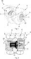
- FIG. 1 a double-flow radial fan 50 is shown with a radial fan housing 1 in a perspective view.
- FIG. 2 shows the same radial fan 50 in a sectional view.
- the radial fan housing 1 comprises a first housing part 2 and an axially separate second housing part 4, in each of which a radial impeller 3, 5 is received with forward curved impeller blades.
- the radial impellers 3, 5 are simultaneously driven in parallel via the motor 12.
- Both housing parts 2, 4 each have an axial intake opening 22, 23, via which the radial fan 50 draws air axially.
- the first and second housing parts 2, 4 of the radial fan housing 1 form a spiral spiral section 6, within which the separately extending flow spaces 8, 9 in the interior of the housing parts 2, 4 radially expand in the circumferential direction.
- the blow-out section 7 of the radial fan housing 1 is also spiral-shaped and increases the pressure space in the blow-out section 7 in the circumferential direction even more than in the spiral section 6.
- the sectional view according to FIG. 2 runs through the spiral section 6 and shows by way of example two pressure compensation openings 10 in the spiral section 6, which connect the first housing part 2 and the second housing part 4 fluidically to equalize the pressure and are formed as channels.
- the channels bridge the axial distance and ensure the pressure balance between the separate housing parts 2, 4 in the spiral section. 6
- FIG. 3 is the double-flow radial fan 50 off FIG. 1 shown as a schematic side view, in which the circumferential course of the spiral section 6 and the adjoining blow-out section 7 with the discharge opening 11 with diameter D can be seen.
- the spiral section 6 is divided in the circumferential direction into four equally sized subsections 41, 42, 43, 44, which when viewed together occupy an angular range ⁇ of 280 °, the discharge section 7 consequently determines an angular range ⁇ of 80 °.
- Fig. 4 shows a schematic side view of a double-flow radial fan in an embodiment according to FIG. 1
- the two housing parts 2, 4 abut each other axially and six pressure equalization openings 10 are provided in the form of round holes uniformly distributed in the circumferential direction over the spiral section 6.
- Each sub-section 41, 42, 43, 44 comprises at least one pressure equalization opening 10. After all pressure equalization openings 10 in FIG. 4 are formed identically large, each of the pressure compensation openings 10 forms about 16.7% of the total opening cross-sectional area.
- FIG. 5 is a variant for execution according to FIG. 4 in which the six pressure compensation openings 10 are provided only in the three subsections 41, 42, 43 located closer to the blow-off section 7 in the flow direction.
- the spiral portion 6 in the circumferential direction, as in FIG. 3 are divided into four equally sized subsections 41, 42, 43, 44, but the pressure equalizing openings 10 are then provided and formed in particular in the two circumferentially adjacent to the blowout section 7 subsections 41, 42 together at least 30% of the total opening cross-sectional area form.
- FIG. 6 is a diagram with measured at identical experimental setup curves for pressure waveform psf [Pa] and the efficiency nse [%] at different flow rates qv [m 3 / h] of the radial fan 50 according to Fig. 1 and the same radial fan without pressure equalization opening in the spiral section, wherein the solid curves in each case the radial fan 50 according to Fig. 1 and the dashed characteristic lines each characterize the radial fan without pressure equalization opening in the spiral section.
- the advantageous effect of the pressure equalization between the housing parts in the spiral section on the efficiency can be clearly seen especially in the particularly important area at a flow rate up to about 500 m 3 / h.
Landscapes
- Engineering & Computer Science (AREA)
- Mechanical Engineering (AREA)
- General Engineering & Computer Science (AREA)
- Structures Of Non-Positive Displacement Pumps (AREA)
Abstract
Description
- Die Erfindung betrifft ein Radialgebläsegehäuse sowie ein Radialgebläse mit einem derartigen Radialgebläsegehäuse, insbesondere zur Verwendung bei Dunstabzugshauben.
- Radialgebläse sind in verschiedenen Ausführungen aus dem Stand der Technik bekannt. Um eine breitflächige Ansaugung bei Dunstabzugshauben mit hohem Volumenstrom zu realisieren, kommen aufgrund der beengten Platzverhältnisse häufig doppelflutige Radialgebläse mit Ansaugöffnungen an zwei axial gegenüberliegenden Seiten zum Einsatz, deren Radialgebläsegehäuse zwei Gehäuseteile zur Aufnahme jeweils eines Lüfterrades aufweisen. Die beiden Lüfterräder erzeugen in den Gehäuseteilen zwei Luftströme. Die zwei Gehäuseteile werden im Ausblasabschnitt des Radialgebläses zusammengeführt, so dass die beiden Luftströme miteinander über eine einzige Ausblasöffnung in das Abzugsrohr ausgeblasen werden. Der Innendurchmesser des Abzugsrohrs ist in vielen Ländern standardisiert und liegt zumeist bei 150mm. Die Ausblasöffnung des Radialgebläses wird entsprechend groß ausgebildet.
- Der Parallelbetrieb der beiden Lüfterräder mit einem einzigen Antriebsmotor wird im Stand der Technik beispielsweise über eine Motorversperrung realisiert. Die dabei erzeugten Luftkennlinien (Wirkungsgrad, Maximaldruck) der einzelnen Laufräder unterscheiden sich unwesentlich. Eine andere Möglichkeit zur Realisierung des Parallelbetriebes der Lüfterräder kann beispielsweise durch einen Antriebsmotor erfolgen, der zwischen den Lüfterrädern angeordnet ist. In Parallelschaltung, d.h. im zusammengeschaltenen Zustand der Laufräder, verändert sich die Situation jedoch deutlich. Die beiden einzelnen Laufräder müssen im Parallelbetrieb jeweils den gleichen Druck erreichen. Dies gelingt bis zu einem bestimmten Druck und Volumenstrom auch, jedoch sinken anschließend sowohl der Wirkungsgrad als auch der Druck deutlich ab. Grund hierfür ist, dass sich das Verhältnis des Druckunterschieds zum Volumenunterschied (dp/dV) eines Laufrads aus dem negativen Bereich in den positiven Bereich verändert, wodurch der jeweilige Arbeitspunkt nicht mehr stationär, sondern unerwünscht instationär ist. Dies führt zum strömungstechnischen "Pumpen" und beeinflusst sowohl den Wirkungsgrad als auch den durch das Radialgebläse erzeugten Druck negativ.
- Der Erfindung liegt deshalb die Aufgabe zugrunde, eine Lösung für Radialgebläse mit mehreren parallel betriebenen Laufrädern bereitzustellen, bei welcher der erreichte Wirkungsgrad über den Verlauf des geförderten Volumenstroms, insbesondere bei Volumenströmen unterhalb des Wirkungsgradmaximums des Radialgebläses verbessert ist.
- Diese Aufgabe wird durch die Merkmalskombination gemäß Anspruch 1 gelöst.
- Erfindungsgemäß wird ein Radialgebläsegehäuse eines Radialgebläses mit einem ersten Gehäuseteil zur Aufnahme eines ersten Radiallaufrads und einem axial unmittelbar daran angrenzenden zweiten Gehäuseteil zur Aufnahme eines zweiten Radiallaufrads vorgeschlagen. Der erste und der zweite Gehäuseteil weisen in einem spiralförmigen Spiralabschnitt des Radialgebläsegehäuses getrennt verlaufende Strömungsräume auf, die in einem sich in Umfangsrichtung gesehen an den Spiralabschnitt unmittelbar anschließenden Ausblasabschnitt des Radialgebläsegehäuses ineinander münden. Der erste Gehäuseteil und der zweite Gehäuseteil sind im Spiralabschnitt über mindestens eine Druckausgleichsöffnung zur Gewährleistung eines Druckausgleichs zwischen den Gehäuseteilen strömungsverbunden.
- Die Strömungsräume im spiralförmigen Spiralabschnitt des Radialgebläsegehäuses bilden jeweils den Druckraum der einzelnen Laufräder, wobei sich die jeweiligen Strömungsräume aufgrund der Spiralform in Umfangsrichtung in Richtung der Ausblasöffnung vergrößern. Die Spiralform kann sich in einer Ausführungsvariante über den gesamten Spiralabschnitt erstrecken. In einer alternativen Ausführung verlaufen die Druckräume in Umfangsrichtung abschnittsweise teils mit konstanter, teils mit spiralförmig zunehmender Strömungsquerschnittsfläche.
- Die mindestens eine Druckausgleichsöffnung im Spiralabschnitt des Radialgebläsegehäuses ermöglicht den Druckausgleich zwischen den Gehäuseteilen bereits bevor die einzelnen Strömungen der jeweiligen Laufräder im Ausblasabschnitt zusammengeführt werden. Daraus ergibt sich die Möglichkeit, beispielsweise durch eine Motorversperrung auftretende Auswirkungen auf das Verhältnis des Druckunterschieds zum Volumenunterschied (dp/dV) des einen Laufrads, durch die strömungstechnische Verbindung mit dem Strömungsraum des anderen Laufrads auszugleichen und einen Druckabfall sowie Wirkungsgradabfall bei einem bestimmten Volumenstrom zu verhindern.
- In einer vorteilhaften Ausführung des Radialgebläsegehäuses ist vorgesehen, dass in dessen Spiralabschnitt in Umfangsrichtung gesehen mehrere, voneinander beabstandet angeordnete Druckausgleichsöffnungen vorgesehen sind. Der Druckausgleich verteilt sich dabei auf mehrere Stellen, so dass in Umfangsrichtung auftretende Schwankungen in den einzelnen Gehäuseteilen wiederholt ausgeglichen werden können. Zudem kann die Strömungsquerschnittsfläche jeder einzelnen Druckausgleichsöffnung reduziert und mithin die Gefahr von Geräuschbildung verringert werden. Dabei ist eine Ausführung besonders günstig, bei der im Spiralabschnitt eine Vielzahl von Druckausgleichsöffnungen vorgesehen ist, die in Umfangsrichtung gleichmäßig, d.h. in Umfangsrichtung in identischem Abstand zueinander verteilt angeordnet sind.
- Als weitere vorteilhafte Ausgestaltung ist das Radialgebläsegehäuse dadurch gekennzeichnet, dass die Druckausgleichsöffnungen jeweils eine identische, insbesondere runde Öffnungsquerschnittsfläche aufweisen. Als Ausführungsvarianten können die Druckausgleichsöffnungen als Bohrungen oder Kanäle ausgebildet sein. Dies begünstigt eine kostengünstige Einbringung in oder Anbringung an die Gehäuseteile. Bei identischer Öffnungsquerschnittsfläche der Druckausgleichsöffnungen, beispielsweise bei einer Lösung mit Bohrungen kann ökonomisch vorteilhaft stets dasselbe Werkzeug eingesetzt werden.
- In einer Weiterbildung des Radialgebläsegehäuses ist vorgesehen, dass neben dem Spiralabschnitt auch der Ausblasabschnitt spiralförmig ausgebildet ist und eine einzige Ausblasöffnung des Radialgebläsegehäuses bildet. Als strömungstechnisch vorteilhafte Größenverteilung wurde bestimmt, dass der Spiralabschnitt des Radialgebläsegehäuses in Umfangsrichtung gesehen einen Winkelbereich von bis zu 280° und der Ausblasabschnitt einen Winkelbereich von mindestens 80° einnimmt. Erfindungsgemäß wird der Ausblasabschnitt so groß wie möglich gestaltet, um einen möglichst langen gemeinsamen Strömungsweg im Ausblasabschnitt der von den beiden Radiallaufrädern erzeugten Einzelströmungen zu gewährleisten.
- Auch die Größe der Druckausgleichsöffnungen beeinflusst die Auswirkung auf den Wirkungsgrad des Radialgebläses erheblich. In einer günstigen Ausführung der Erfindung weisen die eine oder die Vielzahl der Druckausgleichsöffnungen eine Gesamtöffnungsquerschnittsfläche auf, die mindestens 2,7% der Querschnittsfläche der Ausblasöffnung bestimmt. Die Gesamtöffnungsquerschnittsfläche ist vorliegend definiert als die Summe der Öffnungsquerschnittsfläche aller Druckausgleichsöffnungen.
- Auch die Position der Anordnung der Druckausgleichsöffnungen im Spiralabschnitt beeinflusst die Wirkung des Druckausgleichs. Dabei wurde als vorteilhafte Ausgestaltung herausgefunden, dass, wenn der Spiralabschnitt in Umfangsrichtung in vier gleich große Unterabschnitte unterteilt wird, jeder Unterabschnitt mindestens eine Druckausgleichsöffnung umfasst, die mindestens 10% der Gesamtöffnungsquerschnittsfläche bildet.
- Als strömungstechnisch günstige Weiterbildung ist vorgesehen, dass bei einer Unterteilung des Spiralabschnitts in vier gleich große Unterabschnitte jeder Unterabschnitt mindestens eine Druckausgleichsöffnung umfasst, die jeweils identische Öffnungsquerschnittsflächen aufweisen.
- In dieser Betrachtung des in Umfangsrichtung in vier gleich große Unterabschnitte unterteilten Spiralabschnitts sieht eine bezüglich des Wirkungsgrads vorteilhafte Ausführungsvariante vor, dass die beiden sich in Umfangsrichtung an den Ausblasabschnitt angrenzenden Unterabschnitte jeweils mindestens eine Druckausgleichsöffnung umfassen, die zusammen mindestens 30% der Gesamtöffnungsquerschnittsfläche bilden.
- Die Erfindung umfasst zudem ein Radialgebläse mit einem vorstehend beschriebenen Radialgebläsegehäuse in einer beliebigen der beschriebenen Varianten. In dem ersten und dem zweiten Gehäuseteil ist je ein Radiallaufrad angeordnet, die zusammen über einen einzelnen axial angrenzend zu den Radiallaufrädern angeordneten Motor antreibbar und ausgebildet sind, in dem ersten und dem zweiten Gehäuseteil im Spiralabschnitt getrennte Luftvolumenströme zu erzeugen. Die getrennten Luftströme werden im Ausblasabschnitt zusammengeführt und aus der Ausblasöffnung ausgeblasen. Im Spiralabschnitt sind die Luftvolumenströme zwischen dem ersten und dem zweiten Gehäuseteil über die mindestens eine Druckausgleichsöffnung zum Druckausgleich strömungsverbunden. Die sich daraus ergebenden Vorteile sind vorstehend für das Radialgebläsegehäuse beschrieben und gelten entsprechend für das Radialgebläse, das ein derartiges Radialgebläsegehäuse verwendet.
- Vorteilhaft ist die strömungstechnische Wirkung bei einem Radialgebläse, bei dem die Radiallaufräder vorwärts gekrümmte Laufradschaufeln aufweisen.
- Zudem ist bei dem Radialgebläse in einer Ausführung vorgesehen, dass die Radiallaufräder parallelgeschaltet angeordnet und über den Motor jeweils mit identischer Drehzahl antreibbar sind.
- Andere vorteilhafte Weiterbildungen sind in den Unteransprüchen gekennzeichnet bzw. werden nachstehend zusammen mit der Beschreibung der bevorzugten Ausführung der Erfindung anhand der Figuren näher dargestellt. Es zeigen:
- Fig. 1
- eine perspektivische Ansicht eines doppelflutigen Radialgebläses;
- Fig. 2
- eine Schnittansicht des doppelflutigen Radialgebläses aus
Fig. 1 , - Fig. 3
- eine schematische Seitenansicht eines doppelflutigen Radialgebläses,
- Fig. 4
- eine schematische Seitenansicht eines doppelflutigen Radialgebläses als Ausführungsvariante,
- Fig. 5
- eine schematische Seitenansicht eines doppelflutigen Radialgebläses als weitere Ausführungsvariante,
- Fig. 6
- ein Diagramm zur Darstellung des verbesserten Wirkungsgrads.
- In
Figur 1 ist ein doppelflutiges Radialgebläse 50 mit einem Radialgebläsegehäuse 1 in perspektivischer Ansicht gezeigt.Figur 2 zeigt dasselbe Radialgebläse 50 in einer Schnittansicht. Das Radialgebläsegehäuse 1 umfasst einen ersten Gehäuseteil 2 sowie einen axial getrennten zweiten Gehäuseteil 4, in denen jeweils ein Radiallaufrad 3, 5 mit vorwärtsgekrümmten Laufradschaufeln aufgenommen ist. Die Radiallaufräder 3, 5 werden gleichzeitig parallel über den Motor 12 angetrieben. Beide Gehäuseteile 2, 4 weisen jeweils eine axiale Ansaugöffnung 22, 23 auf, über die das Radialgebläse 50 axial Luft ansaugt. - Die ersten und zweiten Gehäusteile 2, 4 des Radialgebläsegehäuses 1 bilden einen spiralförmigen Spiralabschnitt 6, innerhalb dessen sich die getrennt verlaufenden Strömungsräume 8, 9 im Inneren der Gehäuseteile 2, 4 in Umfangsrichtung radial erweitern. In Umfangsrichtung an den Spiralabschnitt 6 unmittelbar angrenzend umfasst das Radialgebläsegehäuse 1 den Ausblasabschnitt 7, in dem die Strömungsräume 8, 9 ineinander in einen einzigen vergrößerten Ausblasraum münden, der sich bis zur Ausblasöffnung 11 erstreckt. Der Ausblasabschnitt 7 des Radialgebläsegehäuses 1 ist ebenfalls spiralförmig und vergrößert den Druckraum im Ausblasabschnitt 7 in Umfangsrichtung gesehen sogar noch stärker als im Spiralabschnitt 6.
- Die Schnittansicht gemäß
Figur 2 verläuft durch den Spiralabschnitt 6 und zeigt beispielhaft zwei Druckausgleichsöffnungen 10 im Spiralabschnitt 6, die den ersten Gehäuseteil 2 und den zweiten Gehäuseteil 4 strömungstechnisch zum Druckausgleich verbinden und als Kanäle ausgebildet sind. Nachdem die beiden Gehäusteile 2, 4 zumindest lokal axial voneinander beabstandet sind, überbrücken die Kanäle den axialen Abstand und gewährleisten den Druckausgleich zwischen den getrennten Gehäuseteilen 2, 4 im Spiralabschnitt 6. - In
Fig. 3 ist das doppelflutige Radialgebläse 50 ausFigur 1 als schematische Seitenansicht dargestellt, in der der umfängliche Verlauf des Spiralabschnitts 6 und des sich daran anschließenden Ausblasabschnitts 7 mit der Ausblasöffnung 11 mit Durchmesser D erkennbar sind. Der Spiralabschnitt 6 ist in Umfangsrichtung in vier gleich große Unterabschnitte 41, 42, 43, 44 unterteilt, die zusammen gesehen einen Winkelbereich α von 280° einnehmen, der Ausblasabschnitt 7 bestimmt demzufolge einen Winkelbereich β von 80°. -
Fig. 4 zeigt eine schematische Seitenansicht eines doppelflutigen Radialgebläses in einer Ausführung gemäßFigur 1 , wobei jedoch die beiden Gehäuseteile 2, 4 axial aneinander anliegen und sechs Druckausgleichsöffnungen 10 in Form von runden Bohrungen gleichmäßig in Umfangsrichtung über den Spiralabschnitt 6 verteilt vorgesehen sind. In Anwendung der Aufteilung gemäßFigur 3 aufFigur 4 , umfasst jeder Unterabschnitt 41, 42, 43, 44 zumindest eine Druckausgleichsöffnung 10. Nachdem alle Druckausgleichsöffnungen 10 inFigur 4 identisch groß ausgebildet sind, bildet jede der Druckausgleichsöffnungen 10 ca. 16,7% der Gesamtöffnungsquerschnittsfläche. Die Druckausgleichsöffnungen 10 sind über den Umfang gleichmäßig mit jeweils identischen Abständen zueinander verteilt vorgesehen, wobei die in Umfangsrichtung gesehen erste Druckausgleichsöffnung 10 bei α=0° und die in Umfangsrichtung gesehen letzte Druckausgleichsöffnung 10 bei α=270° angeordnet ist. -
Figur 5 ist eine Variante zur Ausführung gemäßFigur 4 , bei der die sechs Druckausgleichsöffnungen 10 nur in den in Strömungsrichtung gesehen näher an dem Ausblasabschnitt 7 liegenden drei Unterabschnitten 41, 42, 43 vorgesehen sind. - In einer nicht gezeigten weiteren alternativen Ausführung wird der Spiralabschnitt 6 in Umfangsrichtung, wie in
Figur 3 gezeigt, in vier gleich große Unterabschnitte 41, 42, 43, 44 unterteilt, jedoch sind die Druckausgleichsöffnungen 10 dann insbesondere in den beiden sich in Umfangsrichtung an den Ausblasabschnitt 7 angrenzenden Unterabschnitten 41, 42 vorgesehen und ausgebildet, dass sie zusammen mindestens 30% der Gesamtöffnungsquerschnittsfläche bilden. - Für alle Ausführungsvarianten gilt, dass die Druckausgleichsöffnungen 10 eine Gesamtöffnungsquerschnittsfläche aufweisen, die mindestens 2,7% der Querschnittsfläche der Ausblasöffnung 11 bestimmt. Bei einem üblichen Durchmesser D der Ausblasöffnung von D=150mm und einer Bereitstellung von sechs runden Druckausgleichsöffnungen 10, bedeutet dies einen Mindestdurchmesser der Druckausgleichsöffnungen 10 von 10mm.
- In
Figur 6 ist ein Diagramm mit bei identischem Versuchsaufbau gemessenen Kennlinien zum Druckverlauf psf [Pa] und dem Wirkungsgrad nse [%] bei unterschiedlichen Volumenströmen qv [m3/h] des Radialgebläses 50 gemäßFig. 1 und desselben Radialgebläses ohne Druckausgleichsöffnung im Spiralabschnitt, wobei die durchgezogenen Kennlinien jeweils das Radialgebläse 50 gemäßFig. 1 und die gestrichelten Kennlinien jeweils das Radialgebläse ohne Druckausgleichsöffnung im Spiralabschnitt kennzeichnen. Die vorteilhafte Wirkung des Druckausgleichs zwischen den Gehäuseteilen im Spiralabschnitt auf den Wirkungsgrad ist vor allem in dem besonders wichtigen Bereich bei einem Volumenstrom bis ca. 500 m3/h deutlich zu erkennen.
Claims (15)
- Radialgebläsegehäuse (1) eines Radialgebläses (50) mit einem ersten Gehäuseteil (2) zur Aufnahme eines ersten Radiallaufrads (3) und einem axial unmittelbar daran angrenzenden zweiten Gehäuseteil (4) zur Aufnahme eines zweiten Radiallaufrads (5), wobei der erste und der zweite Gehäuseteil (2, 4) in einem Spiralabschnitt (6) des Radialgebläsegehäuses (1) getrennt verlaufende Strömungsräume (8, 9) aufweisen, die in einem sich in Umfangsrichtung gesehen an den Spiralabschnitt (6) unmittelbar anschließenden Ausblasabschnitt (7) des Radialgebläsegehäuses (1) ineinander münden, wobei der erste Gehäuseteil (2) und der zweite Gehäuseteil (4) im Spiralabschnitt (6) über mindestens eine Druckausgleichsöffnung (10) strömungsverbunden sind.
- Radialgebläsegehäuse nach Anspruch 1, dadurch gekennzeichnet, dass im Spiralabschnitt (6) des Radialgebläsegehäuses (1) in Umfangsrichtung gesehen mehrere, voneinander beabstandet angeordnete Druckausgleichsöffnungen (10) vorgesehen sind.
- Radialgebläsegehäuse nach Anspruch 1 oder 2, dadurch gekennzeichnet, dass der Ausblasabschnitt (7) spiralförmig ausgebildet ist und eine einzige Ausblasöffnung des (11) Radialgebläsegehäuses (1) bildet.
- Radialgebläsegehäuse nach einem der vorigen Ansprüche, dadurch gekennzeichnet, dass der Spiralabschnitt (6) des Radialgebläsegehäuses (1) in Umfangsrichtung gesehen einen Winkelbereich von bis zu 280° und der Ausblasabschnitt (7) einen Winkelbereich von mindestens 80° einnimmt.
- Radialgebläsegehäuse nach einem der vorigen Ansprüche, dadurch gekennzeichnet, dass im Spiralabschnitt (6) eine Vielzahl von Druckausgleichsöffnungen (10) vorgesehen ist, die in Umfangsrichtung gleichmäßig verteilt angeordnet sind.
- Radialgebläsegehäuse nach einem der vorigen Ansprüche 2 - 5, dadurch gekennzeichnet, dass die Druckausgleichsöffnungen (10) jeweils eine identische Öffnungsquerschnittsfläche aufweisen.
- Radialgebläsegehäuse nach einem der vorigen Ansprüche, dadurch gekennzeichnet, dass die eine oder mehreren Druckausgleichsöffnungen (10) als eine oder mehrere Bohrungen oder Kanäle ausgebildet sind.
- Radialgebläsegehäuse nach dem vorigen Anspruch, dadurch gekennzeichnet, dass die eine oder mehreren Druckausgleichsöffnungen (10) jeweils eine runde Querschnittsfläche aufweisen.
- Radialgebläsegehäuse nach einem der vorigen Ansprüche, dadurch gekennzeichnet, dass die eine oder mehreren Druckausgleichsöffnungen (10) eine Gesamtöffnungsquerschnittsfläche aufweisen, die mindestens 2,7% einer Querschnittsfläche der Ausblasöffnung (11) bestimmt.
- Radialgebläsegehäuse nach dem vorigen Anspruch, dadurch gekennzeichnet, dass der Spiralabschnitt (6) in Umfangsrichtung in vier gleich große Unterabschnitte (41, 42, 43, 44) unterteilbar ist, wobei jeder Unterabschnitt (41, 42, 43, 44) mindestens eine Druckausgleichsöffnung (10) umfasst, die mindestens 10% der Gesamtöffnungsquerschnittsfläche bildet.
- Radialgebläsegehäuse nach Anspruch 9 oder 10, dadurch gekennzeichnet, dass der Spiralabschnitt (6) in Umfangsrichtung in vier gleich große Unterabschnitte (41, 42, 43, 44) unterteilbar ist, wobei jeder Unterabschnitt (41, 42, 43, 44) mindestens eine Druckausgleichsöffnung (10) umfasst, die jeweils identische Öffnungsquerschnittsflächen aufweisen.
- Radialgebläsegehäuse nach dem vorigen Anspruch, dadurch gekennzeichnet, dass der Spiralabschnitt (6) in Umfangsrichtung in vier gleich große Unterabschnitte (41, 42, 43, 44) unterteilbar ist, wobei die beiden sich in Umfangsrichtung an den Ausblasabschnitt (7) angrenzenden Unterabschnitte (41, 42) jeweils mindestens eine Druckausgleichsöffnung (10) umfassen, die zusammen mindestens 30% der Gesamtöffnungsquerschnittsfläche bilden.
- Radialgebläse (50) mit einem Radialgebläsegehäuse (1) nach einem der vorigen Ansprüche, wobei je ein Radiallaufrad (3, 5) in dem ersten und dem zweiten Gehäuseteil (2, 4) angeordnet ist, die zusammen über einen einzelnen axial angrenzend zu den Radiallaufrädern (3, 5) angeordneten Motor (12) antreibbar und ausgebildet sind, in dem ersten und dem zweiten Gehäuseteil (2, 4) im Spiralabschnitt (6) getrennte Luftvolumenströme zu erzeugen, die im Ausblasabschnitt (7) zusammengeführt und aus der Ausblasöffnung (11) ausgeblasen werden, wobei die Luftvolumenströme im Spiralabschnitt (6) zwischen dem ersten und dem zweiten Gehäuseteil (2, 4) über die mindestens eine Druckausgleichsöffnung (10) zum Druckausgleich strömungsverbunden sind.
- Radialgebläse nach dem vorigen Anspruch, dadurch gekennzeichnet, dass die Radiallaufräder (3, 5) vorwärts gekrümmte Laufradschaufeln aufweisen.
- Radialgebläse nach Anspruch 13 oder 14, dadurch gekennzeichnet, dass die Radiallaufräder (3, 5) parallelgeschaltet angeordnet und über den Motor (12) jeweils mit identischer Drehzahl antreibbar sind.
Applications Claiming Priority (1)
| Application Number | Priority Date | Filing Date | Title |
|---|---|---|---|
| DE102017126912.6A DE102017126912A1 (de) | 2017-11-15 | 2017-11-15 | Radialgebläsegehäuse und Radialgebläse |
Publications (2)
| Publication Number | Publication Date |
|---|---|
| EP3486494A1 true EP3486494A1 (de) | 2019-05-22 |
| EP3486494B1 EP3486494B1 (de) | 2020-06-17 |
Family
ID=63350468
Family Applications (1)
| Application Number | Title | Priority Date | Filing Date |
|---|---|---|---|
| EP18190075.4A Active EP3486494B1 (de) | 2017-11-15 | 2018-08-21 | Radialgebläsegehäuse und radialgebläse |
Country Status (3)
| Country | Link |
|---|---|
| EP (1) | EP3486494B1 (de) |
| CN (1) | CN207999390U (de) |
| DE (1) | DE102017126912A1 (de) |
Families Citing this family (1)
| Publication number | Priority date | Publication date | Assignee | Title |
|---|---|---|---|---|
| DE102020216155A1 (de) * | 2020-12-17 | 2022-06-23 | Ziehl-Abegg Se | Ventilator und Spiralgehäuse für einen Ventilator |
Citations (4)
| Publication number | Priority date | Publication date | Assignee | Title |
|---|---|---|---|---|
| US2710573A (en) * | 1951-04-30 | 1955-06-14 | Trade Wind Motorfans Inc | Air handling apparatus |
| US3469772A (en) * | 1967-07-19 | 1969-09-30 | Donald A Mcdonald | Air moving apparatus |
| JP2001027199A (ja) * | 1999-07-15 | 2001-01-30 | Mitsubishi Heavy Ind Ltd | 両吸込多翼送風装置 |
| US20130101451A1 (en) * | 2011-10-20 | 2013-04-25 | The Bergquist-Torrington Company | Double Inlet Centrifugal Blower with a Solid Center Plate |
Family Cites Families (1)
| Publication number | Priority date | Publication date | Assignee | Title |
|---|---|---|---|---|
| US3874191A (en) * | 1974-06-12 | 1975-04-01 | Molded Products Company | Blower housing |
-
2017
- 2017-11-15 DE DE102017126912.6A patent/DE102017126912A1/de not_active Withdrawn
-
2018
- 2018-01-08 CN CN201820025182.1U patent/CN207999390U/zh active Active
- 2018-08-21 EP EP18190075.4A patent/EP3486494B1/de active Active
Patent Citations (4)
| Publication number | Priority date | Publication date | Assignee | Title |
|---|---|---|---|---|
| US2710573A (en) * | 1951-04-30 | 1955-06-14 | Trade Wind Motorfans Inc | Air handling apparatus |
| US3469772A (en) * | 1967-07-19 | 1969-09-30 | Donald A Mcdonald | Air moving apparatus |
| JP2001027199A (ja) * | 1999-07-15 | 2001-01-30 | Mitsubishi Heavy Ind Ltd | 両吸込多翼送風装置 |
| US20130101451A1 (en) * | 2011-10-20 | 2013-04-25 | The Bergquist-Torrington Company | Double Inlet Centrifugal Blower with a Solid Center Plate |
Also Published As
| Publication number | Publication date |
|---|---|
| CN207999390U (zh) | 2018-10-23 |
| DE102017126912A1 (de) | 2019-05-16 |
| EP3486494B1 (de) | 2020-06-17 |
Similar Documents
| Publication | Publication Date | Title |
|---|---|---|
| DE60211061T2 (de) | Axialturbine mit einer Stufe in einem Abströmkanal | |
| EP3372838B1 (de) | Raumlufttechnische lüftungsanlage mit einer luftleitanordnung | |
| DE102004023270A1 (de) | Axialschraubengebläse | |
| DE102009052619A1 (de) | Zwischenboden für eine Radialturbomaschine | |
| WO2017093245A1 (de) | Lüfterrad für einen axiallüfter | |
| WO2017013021A1 (de) | Seitenkanal-maschine (verdichter, vakuumpumpe oder gebläse) mit einem entnahmekanal im abstreifer | |
| DE102017110642A1 (de) | Gebläseanordnung mit Strömungsteilungsdüse | |
| DE102015111746A1 (de) | Gekühltes Turbinenlaufrad, insbesondere für ein Flugtriebwerk | |
| DE202018106504U1 (de) | Kompakter Diagonalventilator mit Nachleiteinrichtung | |
| WO2016110373A1 (de) | Seitenkanalgebläse für eine verbrennungskraftmaschine | |
| DE102014019147A1 (de) | Luftleitung für einen Ansaugtrakt einer Verbrennungskraftmaschine, insbesondere eines Kraftwagens | |
| EP1288435B1 (de) | Turbinenschaufel mit zumindest einer Kühlungsöffnung | |
| WO2019034740A1 (de) | Diffusor für einen radialverdichter | |
| EP3592987B1 (de) | Halbspiralgehäuse | |
| EP3486494B1 (de) | Radialgebläsegehäuse und radialgebläse | |
| EP1757814A1 (de) | Kreiselverdichter | |
| DE102010044819B4 (de) | Axialturbine und ein Verfahren zum Abführen eines Stroms von einer Axialturbine | |
| DE202013004444U1 (de) | Laufschaufel für einen Verdichter und Verdichter mit einer solchen Laufschaufel | |
| DE102016203305A1 (de) | Rückführstufe, Radialturbofluidenergiemaschine | |
| DE102019220089A1 (de) | Düsenelement für einen Strahlventilator und Strahlventilator | |
| DE202017106947U1 (de) | Radialgebläsegehäuse und Radialgebläse | |
| DE102019108811B4 (de) | Laufschaufel einer Strömungsmaschine | |
| CH650563A5 (en) | Diffuser in a centrifugal driven machine | |
| EP3577346B1 (de) | Turboverdichter mit integrierten strömungskanälen | |
| DE102013008145A1 (de) | Laufschaufel für einen Verdichter und Verdichter mit einer solchen Laufschaufel |
Legal Events
| Date | Code | Title | Description |
|---|---|---|---|
| PUAI | Public reference made under article 153(3) epc to a published international application that has entered the european phase |
Free format text: ORIGINAL CODE: 0009012 |
|
| STAA | Information on the status of an ep patent application or granted ep patent |
Free format text: STATUS: THE APPLICATION HAS BEEN PUBLISHED |
|
| AK | Designated contracting states |
Kind code of ref document: A1 Designated state(s): AL AT BE BG CH CY CZ DE DK EE ES FI FR GB GR HR HU IE IS IT LI LT LU LV MC MK MT NL NO PL PT RO RS SE SI SK SM TR |
|
| AX | Request for extension of the european patent |
Extension state: BA ME |
|
| STAA | Information on the status of an ep patent application or granted ep patent |
Free format text: STATUS: REQUEST FOR EXAMINATION WAS MADE |
|
| 17P | Request for examination filed |
Effective date: 20191028 |
|
| RBV | Designated contracting states (corrected) |
Designated state(s): AL AT BE BG CH CY CZ DE DK EE ES FI FR GB GR HR HU IE IS IT LI LT LU LV MC MK MT NL NO PL PT RO RS SE SI SK SM TR |
|
| GRAP | Despatch of communication of intention to grant a patent |
Free format text: ORIGINAL CODE: EPIDOSNIGR1 |
|
| STAA | Information on the status of an ep patent application or granted ep patent |
Free format text: STATUS: GRANT OF PATENT IS INTENDED |
|
| GRAS | Grant fee paid |
Free format text: ORIGINAL CODE: EPIDOSNIGR3 |
|
| INTG | Intention to grant announced |
Effective date: 20200324 |
|
| GRAA | (expected) grant |
Free format text: ORIGINAL CODE: 0009210 |
|
| STAA | Information on the status of an ep patent application or granted ep patent |
Free format text: STATUS: THE PATENT HAS BEEN GRANTED |
|
| AK | Designated contracting states |
Kind code of ref document: B1 Designated state(s): AL AT BE BG CH CY CZ DE DK EE ES FI FR GB GR HR HU IE IS IT LI LT LU LV MC MK MT NL NO PL PT RO RS SE SI SK SM TR |
|
| REG | Reference to a national code |
Ref country code: GB Ref legal event code: FG4D Free format text: NOT ENGLISH |
|
| REG | Reference to a national code |
Ref country code: CH Ref legal event code: EP |
|
| REG | Reference to a national code |
Ref country code: DE Ref legal event code: R096 Ref document number: 502018001687 Country of ref document: DE |
|
| REG | Reference to a national code |
Ref country code: IE Ref legal event code: FG4D Free format text: LANGUAGE OF EP DOCUMENT: GERMAN |
|
| REG | Reference to a national code |
Ref country code: AT Ref legal event code: REF Ref document number: 1281633 Country of ref document: AT Kind code of ref document: T Effective date: 20200715 |
|
| REG | Reference to a national code |
Ref country code: NL Ref legal event code: FP |
|
| REG | Reference to a national code |
Ref country code: SE Ref legal event code: TRGR |
|
| PG25 | Lapsed in a contracting state [announced via postgrant information from national office to epo] |
Ref country code: GR Free format text: LAPSE BECAUSE OF FAILURE TO SUBMIT A TRANSLATION OF THE DESCRIPTION OR TO PAY THE FEE WITHIN THE PRESCRIBED TIME-LIMIT Effective date: 20200918 Ref country code: NO Free format text: LAPSE BECAUSE OF FAILURE TO SUBMIT A TRANSLATION OF THE DESCRIPTION OR TO PAY THE FEE WITHIN THE PRESCRIBED TIME-LIMIT Effective date: 20200917 Ref country code: LT Free format text: LAPSE BECAUSE OF FAILURE TO SUBMIT A TRANSLATION OF THE DESCRIPTION OR TO PAY THE FEE WITHIN THE PRESCRIBED TIME-LIMIT Effective date: 20200617 Ref country code: FI Free format text: LAPSE BECAUSE OF FAILURE TO SUBMIT A TRANSLATION OF THE DESCRIPTION OR TO PAY THE FEE WITHIN THE PRESCRIBED TIME-LIMIT Effective date: 20200617 |
|
| REG | Reference to a national code |
Ref country code: LT Ref legal event code: MG4D |
|
| PG25 | Lapsed in a contracting state [announced via postgrant information from national office to epo] |
Ref country code: LV Free format text: LAPSE BECAUSE OF FAILURE TO SUBMIT A TRANSLATION OF THE DESCRIPTION OR TO PAY THE FEE WITHIN THE PRESCRIBED TIME-LIMIT Effective date: 20200617 Ref country code: HR Free format text: LAPSE BECAUSE OF FAILURE TO SUBMIT A TRANSLATION OF THE DESCRIPTION OR TO PAY THE FEE WITHIN THE PRESCRIBED TIME-LIMIT Effective date: 20200617 Ref country code: RS Free format text: LAPSE BECAUSE OF FAILURE TO SUBMIT A TRANSLATION OF THE DESCRIPTION OR TO PAY THE FEE WITHIN THE PRESCRIBED TIME-LIMIT Effective date: 20200617 Ref country code: BG Free format text: LAPSE BECAUSE OF FAILURE TO SUBMIT A TRANSLATION OF THE DESCRIPTION OR TO PAY THE FEE WITHIN THE PRESCRIBED TIME-LIMIT Effective date: 20200917 |
|
| PG25 | Lapsed in a contracting state [announced via postgrant information from national office to epo] |
Ref country code: AL Free format text: LAPSE BECAUSE OF FAILURE TO SUBMIT A TRANSLATION OF THE DESCRIPTION OR TO PAY THE FEE WITHIN THE PRESCRIBED TIME-LIMIT Effective date: 20200617 |
|
| PG25 | Lapsed in a contracting state [announced via postgrant information from national office to epo] |
Ref country code: PT Free format text: LAPSE BECAUSE OF FAILURE TO SUBMIT A TRANSLATION OF THE DESCRIPTION OR TO PAY THE FEE WITHIN THE PRESCRIBED TIME-LIMIT Effective date: 20201019 Ref country code: ES Free format text: LAPSE BECAUSE OF FAILURE TO SUBMIT A TRANSLATION OF THE DESCRIPTION OR TO PAY THE FEE WITHIN THE PRESCRIBED TIME-LIMIT Effective date: 20200617 Ref country code: RO Free format text: LAPSE BECAUSE OF FAILURE TO SUBMIT A TRANSLATION OF THE DESCRIPTION OR TO PAY THE FEE WITHIN THE PRESCRIBED TIME-LIMIT Effective date: 20200617 Ref country code: SM Free format text: LAPSE BECAUSE OF FAILURE TO SUBMIT A TRANSLATION OF THE DESCRIPTION OR TO PAY THE FEE WITHIN THE PRESCRIBED TIME-LIMIT Effective date: 20200617 Ref country code: EE Free format text: LAPSE BECAUSE OF FAILURE TO SUBMIT A TRANSLATION OF THE DESCRIPTION OR TO PAY THE FEE WITHIN THE PRESCRIBED TIME-LIMIT Effective date: 20200617 |
|
| PG25 | Lapsed in a contracting state [announced via postgrant information from national office to epo] |
Ref country code: IS Free format text: LAPSE BECAUSE OF FAILURE TO SUBMIT A TRANSLATION OF THE DESCRIPTION OR TO PAY THE FEE WITHIN THE PRESCRIBED TIME-LIMIT Effective date: 20201017 Ref country code: SK Free format text: LAPSE BECAUSE OF FAILURE TO SUBMIT A TRANSLATION OF THE DESCRIPTION OR TO PAY THE FEE WITHIN THE PRESCRIBED TIME-LIMIT Effective date: 20200617 Ref country code: PL Free format text: LAPSE BECAUSE OF FAILURE TO SUBMIT A TRANSLATION OF THE DESCRIPTION OR TO PAY THE FEE WITHIN THE PRESCRIBED TIME-LIMIT Effective date: 20200617 |
|
| REG | Reference to a national code |
Ref country code: DE Ref legal event code: R097 Ref document number: 502018001687 Country of ref document: DE |
|
| PG25 | Lapsed in a contracting state [announced via postgrant information from national office to epo] |
Ref country code: MC Free format text: LAPSE BECAUSE OF FAILURE TO SUBMIT A TRANSLATION OF THE DESCRIPTION OR TO PAY THE FEE WITHIN THE PRESCRIBED TIME-LIMIT Effective date: 20200617 |
|
| PLBE | No opposition filed within time limit |
Free format text: ORIGINAL CODE: 0009261 |
|
| STAA | Information on the status of an ep patent application or granted ep patent |
Free format text: STATUS: NO OPPOSITION FILED WITHIN TIME LIMIT |
|
| PG25 | Lapsed in a contracting state [announced via postgrant information from national office to epo] |
Ref country code: LU Free format text: LAPSE BECAUSE OF NON-PAYMENT OF DUE FEES Effective date: 20200821 Ref country code: DK Free format text: LAPSE BECAUSE OF FAILURE TO SUBMIT A TRANSLATION OF THE DESCRIPTION OR TO PAY THE FEE WITHIN THE PRESCRIBED TIME-LIMIT Effective date: 20200617 |
|
| 26N | No opposition filed |
Effective date: 20210318 |
|
| REG | Reference to a national code |
Ref country code: BE Ref legal event code: MM Effective date: 20200831 |
|
| PG25 | Lapsed in a contracting state [announced via postgrant information from national office to epo] |
Ref country code: SI Free format text: LAPSE BECAUSE OF FAILURE TO SUBMIT A TRANSLATION OF THE DESCRIPTION OR TO PAY THE FEE WITHIN THE PRESCRIBED TIME-LIMIT Effective date: 20200617 |
|
| PG25 | Lapsed in a contracting state [announced via postgrant information from national office to epo] |
Ref country code: BE Free format text: LAPSE BECAUSE OF NON-PAYMENT OF DUE FEES Effective date: 20200831 Ref country code: IE Free format text: LAPSE BECAUSE OF NON-PAYMENT OF DUE FEES Effective date: 20200821 |
|
| REG | Reference to a national code |
Ref country code: CH Ref legal event code: PL |
|
| PG25 | Lapsed in a contracting state [announced via postgrant information from national office to epo] |
Ref country code: LI Free format text: LAPSE BECAUSE OF NON-PAYMENT OF DUE FEES Effective date: 20210831 Ref country code: CH Free format text: LAPSE BECAUSE OF NON-PAYMENT OF DUE FEES Effective date: 20210831 |
|
| PG25 | Lapsed in a contracting state [announced via postgrant information from national office to epo] |
Ref country code: TR Free format text: LAPSE BECAUSE OF FAILURE TO SUBMIT A TRANSLATION OF THE DESCRIPTION OR TO PAY THE FEE WITHIN THE PRESCRIBED TIME-LIMIT Effective date: 20200617 Ref country code: MT Free format text: LAPSE BECAUSE OF FAILURE TO SUBMIT A TRANSLATION OF THE DESCRIPTION OR TO PAY THE FEE WITHIN THE PRESCRIBED TIME-LIMIT Effective date: 20200617 Ref country code: CY Free format text: LAPSE BECAUSE OF FAILURE TO SUBMIT A TRANSLATION OF THE DESCRIPTION OR TO PAY THE FEE WITHIN THE PRESCRIBED TIME-LIMIT Effective date: 20200617 |
|
| PG25 | Lapsed in a contracting state [announced via postgrant information from national office to epo] |
Ref country code: MK Free format text: LAPSE BECAUSE OF FAILURE TO SUBMIT A TRANSLATION OF THE DESCRIPTION OR TO PAY THE FEE WITHIN THE PRESCRIBED TIME-LIMIT Effective date: 20200617 |
|
| P01 | Opt-out of the competence of the unified patent court (upc) registered |
Effective date: 20230522 |
|
| PGFP | Annual fee paid to national office [announced via postgrant information from national office to epo] |
Ref country code: NL Payment date: 20250821 Year of fee payment: 8 |
|
| PGFP | Annual fee paid to national office [announced via postgrant information from national office to epo] |
Ref country code: DE Payment date: 20250819 Year of fee payment: 8 |
|
| PGFP | Annual fee paid to national office [announced via postgrant information from national office to epo] |
Ref country code: IT Payment date: 20250829 Year of fee payment: 8 |
|
| PGFP | Annual fee paid to national office [announced via postgrant information from national office to epo] |
Ref country code: GB Payment date: 20250822 Year of fee payment: 8 |
|
| PGFP | Annual fee paid to national office [announced via postgrant information from national office to epo] |
Ref country code: FR Payment date: 20250821 Year of fee payment: 8 Ref country code: AT Payment date: 20250819 Year of fee payment: 8 |
|
| PGFP | Annual fee paid to national office [announced via postgrant information from national office to epo] |
Ref country code: SE Payment date: 20250821 Year of fee payment: 8 |
|
| PGFP | Annual fee paid to national office [announced via postgrant information from national office to epo] |
Ref country code: CZ Payment date: 20250808 Year of fee payment: 8 |