EP3486478A1 - Wind turbine apparatus - Google Patents
Wind turbine apparatus Download PDFInfo
- Publication number
- EP3486478A1 EP3486478A1 EP18215972.3A EP18215972A EP3486478A1 EP 3486478 A1 EP3486478 A1 EP 3486478A1 EP 18215972 A EP18215972 A EP 18215972A EP 3486478 A1 EP3486478 A1 EP 3486478A1
- Authority
- EP
- European Patent Office
- Prior art keywords
- rotor
- blade portion
- yoke
- wind turbine
- generator
- Prior art date
- Legal status (The legal status is an assumption and is not a legal conclusion. Google has not performed a legal analysis and makes no representation as to the accuracy of the status listed.)
- Granted
Links
- 230000008878 coupling Effects 0.000 claims description 8
- 238000010168 coupling process Methods 0.000 claims description 8
- 238000005859 coupling reaction Methods 0.000 claims description 8
- 230000007246 mechanism Effects 0.000 claims description 4
- 230000014759 maintenance of location Effects 0.000 description 22
- 239000004020 conductor Substances 0.000 description 5
- 239000000463 material Substances 0.000 description 5
- 230000000295 complement effect Effects 0.000 description 4
- 230000000694 effects Effects 0.000 description 4
- 229910000831 Steel Inorganic materials 0.000 description 3
- 239000004411 aluminium Substances 0.000 description 3
- 229910052782 aluminium Inorganic materials 0.000 description 3
- XAGFODPZIPBFFR-UHFFFAOYSA-N aluminium Chemical compound [Al] XAGFODPZIPBFFR-UHFFFAOYSA-N 0.000 description 3
- 230000007935 neutral effect Effects 0.000 description 3
- 239000007787 solid Substances 0.000 description 3
- 239000010959 steel Substances 0.000 description 3
- 230000004323 axial length Effects 0.000 description 2
- 239000002131 composite material Substances 0.000 description 2
- 230000005611 electricity Effects 0.000 description 2
- 239000012212 insulator Substances 0.000 description 2
- 239000002184 metal Substances 0.000 description 2
- 229910052751 metal Inorganic materials 0.000 description 2
- 229910000838 Al alloy Inorganic materials 0.000 description 1
- 229910001369 Brass Inorganic materials 0.000 description 1
- RYGMFSIKBFXOCR-UHFFFAOYSA-N Copper Chemical compound [Cu] RYGMFSIKBFXOCR-UHFFFAOYSA-N 0.000 description 1
- 239000004593 Epoxy Substances 0.000 description 1
- 230000009471 action Effects 0.000 description 1
- 230000009286 beneficial effect Effects 0.000 description 1
- 239000010951 brass Substances 0.000 description 1
- -1 but not limited to Substances 0.000 description 1
- 239000000470 constituent Substances 0.000 description 1
- 238000010276 construction Methods 0.000 description 1
- 239000010949 copper Substances 0.000 description 1
- 229910052802 copper Inorganic materials 0.000 description 1
- 229920006332 epoxy adhesive Polymers 0.000 description 1
- 230000004907 flux Effects 0.000 description 1
- 239000011521 glass Substances 0.000 description 1
- 239000011810 insulating material Substances 0.000 description 1
- 238000012423 maintenance Methods 0.000 description 1
- 238000004519 manufacturing process Methods 0.000 description 1
- 150000002739 metals Chemical class 0.000 description 1
- 238000013021 overheating Methods 0.000 description 1
- 229920000642 polymer Polymers 0.000 description 1
- 230000009467 reduction Effects 0.000 description 1
- 230000004044 response Effects 0.000 description 1
- 230000000717 retained effect Effects 0.000 description 1
- 230000001360 synchronised effect Effects 0.000 description 1
- 229920001169 thermoplastic Polymers 0.000 description 1
- 229920001187 thermosetting polymer Polymers 0.000 description 1
- 239000004416 thermosoftening plastic Substances 0.000 description 1
Images


Classifications
-
- F—MECHANICAL ENGINEERING; LIGHTING; HEATING; WEAPONS; BLASTING
- F03—MACHINES OR ENGINES FOR LIQUIDS; WIND, SPRING, OR WEIGHT MOTORS; PRODUCING MECHANICAL POWER OR A REACTIVE PROPULSIVE THRUST, NOT OTHERWISE PROVIDED FOR
- F03D—WIND MOTORS
- F03D3/00—Wind motors with rotation axis substantially perpendicular to the air flow entering the rotor
- F03D3/06—Rotors
- F03D3/062—Rotors characterised by their construction elements
-
- F—MECHANICAL ENGINEERING; LIGHTING; HEATING; WEAPONS; BLASTING
- F03—MACHINES OR ENGINES FOR LIQUIDS; WIND, SPRING, OR WEIGHT MOTORS; PRODUCING MECHANICAL POWER OR A REACTIVE PROPULSIVE THRUST, NOT OTHERWISE PROVIDED FOR
- F03D—WIND MOTORS
- F03D3/00—Wind motors with rotation axis substantially perpendicular to the air flow entering the rotor
- F03D3/02—Wind motors with rotation axis substantially perpendicular to the air flow entering the rotor having a plurality of rotors
-
- F—MECHANICAL ENGINEERING; LIGHTING; HEATING; WEAPONS; BLASTING
- F03—MACHINES OR ENGINES FOR LIQUIDS; WIND, SPRING, OR WEIGHT MOTORS; PRODUCING MECHANICAL POWER OR A REACTIVE PROPULSIVE THRUST, NOT OTHERWISE PROVIDED FOR
- F03D—WIND MOTORS
- F03D3/00—Wind motors with rotation axis substantially perpendicular to the air flow entering the rotor
- F03D3/06—Rotors
- F03D3/062—Rotors characterised by their construction elements
- F03D3/064—Fixing wind engaging parts to rest of rotor
-
- F—MECHANICAL ENGINEERING; LIGHTING; HEATING; WEAPONS; BLASTING
- F03—MACHINES OR ENGINES FOR LIQUIDS; WIND, SPRING, OR WEIGHT MOTORS; PRODUCING MECHANICAL POWER OR A REACTIVE PROPULSIVE THRUST, NOT OTHERWISE PROVIDED FOR
- F03D—WIND MOTORS
- F03D15/00—Transmission of mechanical power
-
- F—MECHANICAL ENGINEERING; LIGHTING; HEATING; WEAPONS; BLASTING
- F03—MACHINES OR ENGINES FOR LIQUIDS; WIND, SPRING, OR WEIGHT MOTORS; PRODUCING MECHANICAL POWER OR A REACTIVE PROPULSIVE THRUST, NOT OTHERWISE PROVIDED FOR
- F03D—WIND MOTORS
- F03D3/00—Wind motors with rotation axis substantially perpendicular to the air flow entering the rotor
-
- F—MECHANICAL ENGINEERING; LIGHTING; HEATING; WEAPONS; BLASTING
- F03—MACHINES OR ENGINES FOR LIQUIDS; WIND, SPRING, OR WEIGHT MOTORS; PRODUCING MECHANICAL POWER OR A REACTIVE PROPULSIVE THRUST, NOT OTHERWISE PROVIDED FOR
- F03D—WIND MOTORS
- F03D80/00—Details, components or accessories not provided for in groups F03D1/00 - F03D17/00
- F03D80/80—Arrangement of components within nacelles or towers
- F03D80/82—Arrangement of components within nacelles or towers of electrical components
-
- F—MECHANICAL ENGINEERING; LIGHTING; HEATING; WEAPONS; BLASTING
- F03—MACHINES OR ENGINES FOR LIQUIDS; WIND, SPRING, OR WEIGHT MOTORS; PRODUCING MECHANICAL POWER OR A REACTIVE PROPULSIVE THRUST, NOT OTHERWISE PROVIDED FOR
- F03D—WIND MOTORS
- F03D9/00—Adaptations of wind motors for special use; Combinations of wind motors with apparatus driven thereby; Wind motors specially adapted for installation in particular locations
- F03D9/20—Wind motors characterised by the driven apparatus
- F03D9/25—Wind motors characterised by the driven apparatus the apparatus being an electrical generator
-
- H—ELECTRICITY
- H02—GENERATION; CONVERSION OR DISTRIBUTION OF ELECTRIC POWER
- H02K—DYNAMO-ELECTRIC MACHINES
- H02K7/00—Arrangements for handling mechanical energy structurally associated with dynamo-electric machines, e.g. structural association with mechanical driving motors or auxiliary dynamo-electric machines
- H02K7/18—Structural association of electric generators with mechanical driving motors, e.g. with turbines
- H02K7/1807—Rotary generators
- H02K7/1823—Rotary generators structurally associated with turbines or similar engines
- H02K7/183—Rotary generators structurally associated with turbines or similar engines wherein the turbine is a wind turbine
-
- F—MECHANICAL ENGINEERING; LIGHTING; HEATING; WEAPONS; BLASTING
- F05—INDEXING SCHEMES RELATING TO ENGINES OR PUMPS IN VARIOUS SUBCLASSES OF CLASSES F01-F04
- F05B—INDEXING SCHEME RELATING TO WIND, SPRING, WEIGHT, INERTIA OR LIKE MOTORS, TO MACHINES OR ENGINES FOR LIQUIDS COVERED BY SUBCLASSES F03B, F03D AND F03G
- F05B2220/00—Application
- F05B2220/70—Application in combination with
- F05B2220/706—Application in combination with an electrical generator
- F05B2220/7066—Application in combination with an electrical generator via a direct connection, i.e. a gearless transmission
-
- F—MECHANICAL ENGINEERING; LIGHTING; HEATING; WEAPONS; BLASTING
- F05—INDEXING SCHEMES RELATING TO ENGINES OR PUMPS IN VARIOUS SUBCLASSES OF CLASSES F01-F04
- F05B—INDEXING SCHEME RELATING TO WIND, SPRING, WEIGHT, INERTIA OR LIKE MOTORS, TO MACHINES OR ENGINES FOR LIQUIDS COVERED BY SUBCLASSES F03B, F03D AND F03G
- F05B2220/00—Application
- F05B2220/70—Application in combination with
- F05B2220/706—Application in combination with an electrical generator
- F05B2220/7068—Application in combination with an electrical generator equipped with permanent magnets
-
- F—MECHANICAL ENGINEERING; LIGHTING; HEATING; WEAPONS; BLASTING
- F05—INDEXING SCHEMES RELATING TO ENGINES OR PUMPS IN VARIOUS SUBCLASSES OF CLASSES F01-F04
- F05B—INDEXING SCHEME RELATING TO WIND, SPRING, WEIGHT, INERTIA OR LIKE MOTORS, TO MACHINES OR ENGINES FOR LIQUIDS COVERED BY SUBCLASSES F03B, F03D AND F03G
- F05B2260/00—Function
- F05B2260/30—Retaining components in desired mutual position
-
- Y—GENERAL TAGGING OF NEW TECHNOLOGICAL DEVELOPMENTS; GENERAL TAGGING OF CROSS-SECTIONAL TECHNOLOGIES SPANNING OVER SEVERAL SECTIONS OF THE IPC; TECHNICAL SUBJECTS COVERED BY FORMER USPC CROSS-REFERENCE ART COLLECTIONS [XRACs] AND DIGESTS
- Y02—TECHNOLOGIES OR APPLICATIONS FOR MITIGATION OR ADAPTATION AGAINST CLIMATE CHANGE
- Y02E—REDUCTION OF GREENHOUSE GAS [GHG] EMISSIONS, RELATED TO ENERGY GENERATION, TRANSMISSION OR DISTRIBUTION
- Y02E10/00—Energy generation through renewable energy sources
- Y02E10/70—Wind energy
- Y02E10/74—Wind turbines with rotation axis perpendicular to the wind direction
Definitions
- the invention relates wind turbine apparatuses and particularly, but not exclusively to wind turbine apparatuses comprising a plurality of turbine modules.
- VAWT vertical axis wind turbine
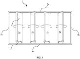
- FIG. 1 the frame 1 is formed by upper and lower structural rails 3a, 3b and left and right side members 5a, 5b to form a rectangular frame.
- a plurality (four are shown) of wind turbine modules 7a-7d are located within the frame 1 and are spaced from one another along the width of the frame 1.
- the modules 7a-7d are affixed at either end to the upper and lower structural rails 3a, 3b.
- Each module 7a-7d comprises a blade portion 9 and a generator 11 coupled thereto.
- FIGS 2 and 3 show an exemplary axial-flux generator 11 in further detail.
- the generator 11 comprises a rotor 13 and a stator 15.
- the rotor 13 is formed by an outer housing of the generator 11 which is connected to the blade portion 9 for rotation therewith.
- the stator 15 is formed by a shaft 17 which is affixed to the lower rail 3b.
- the rotor 13 is rotatably mounted to the shaft 17 by upper and lower bearings 21a, 21b.
- the shaft 17 carries a disc 19 which has a plurality of coils 23 arranged in a circle.
- the rotor 13 carries a plurality of permanent magnets 25.
- the permanent magnets 25 are arranged in an upper circle and a lower circle which correspond with the circle of coils 23.
- the coils 23 are sandwiched between the upper and lower sets of magnets 25 with a small gap therebetween to allow free movement of the magnets 25 relative to the coils 23.
- Rotation of the blade portion 9 in response to the force of wind causes rotation of the rotor 13.
- the movement of the magnets 25 relative to the coils 23 induces a current in the coils 23 which can be harnessed as useful electricity.
- the rotor 13 is supported by a pair of bearings 21a, 21b which maintain alignment between the rotor 13 and the stator 15 such that the distance between the coils 23 and magnets 25 can be minimised, thereby improving efficiency. While such an arrangement addresses axial misalignment issues between the rotor 13 and stator 15, in order for the blade portion 9 and rotor 13 to rotate freely, the centre of the bearing supporting the upper end of the blade portion 9 (at the upper rail 3a) must lie on the axis defined by the centres of the two bearings 21a, 21b within the generator 11.
- a flexible coupling between the blade portion 9 and the rotor 13 may be introduced to allow the rotation axis of the blade portion 9 to deviate slightly from that of the generator 11 without damaging either component.
- Such an arrangement can, however, create a new issue in that a high torque (perpendicular to the rotation axis) is generated on the lower rail 3b which supports the generator 11.
- the shaft 17 in order to carry the generated current away from the coils 23, it is necessary for the shaft 17 to be hollow so that suitable wiring can pass through the shaft 17.
- the shaft 17 carries the weight of the generator 11 and must withstand in-service loads.
- such shafts are conventionally constructed from relatively high strength steel so as to give them the necessary strength and rigidity.
- a wind turbine apparatus comprising: a blade portion; a generator comprising a stator having a plurality of coils and a rotor having a plurality of magnets, the rotor being connected to the blade portion such that rotation of the blade portion and rotor generates a current within the coils; wherein the blade portion is connected to the rotor by a yoke which extends around the generator and is connected to the base of the rotor such that the magnets of the rotor and the coils of the stator are disposed between the blade portion and the connection between the yoke and the rotor.
- the stator may comprise a shaft which is received by a supporting rail.
- connection between the yoke and the rotor may be disposed between the supporting rail and the magnets and coils.
- the rotor may be rotatably mounted on the stator by a bearing, and the connection between the yoke and the rotor may be formed around the bearing.
- the yoke may be compliant so as to allow the rotation axes of the blade portion and the rotor to be offset from one another.
- the yoke may be connected to the blade portion and/or the rotor via a compliant coupling so as to allow the rotation axes of the blade portion and the rotor to be offset from one another.
- the yoke may be connected to the blade portion and/or the generator via a quick-release mechanism.
- a wind turbine apparatus comprising: a blade portion; a generator comprising a stator having a plurality of coils and a rotor having a plurality of magnets, the rotor being connected to the blade portion such that rotation of the blade portion and the rotor generates a current within the coils; wherein the stator comprises a shaft, the shaft having a first terminal portion and a second terminal portion separated from one another by an insulator, the first and second terminal portions being electrically connected to the coils; wherein the shaft is received by openings provided in first and second conductive rails so as to support the generator and blade portion and such that the first and second terminal portions are electrically coupled to the first and second conductive rails respectively to carry the current from the coils.
- the holes in the first and second conductive rails may have complementary cross-sections to the first and second terminal portions.
- the first terminal portion may be formed by a pin and the second terminal portion may be formed by a sleeve which surrounds the pin.
- the pin may project from the sleeve such that the pin is received by the second conductive rail when the sleeve is received by the first conductive rail.
- the pin and sleeve may be concentric.
- the sleeve may have a first diameter and the pin may have a second diameter which is smaller than the first diameter.
- the openings of the first and second rails may be sized to receive the first and second diameters respectively.
- the first and/or second rail may be provided with a retention member having or defining a hole sized to receive the first or second terminal portion.
- the retention member may be configured to be aligned with the rail so that the terminal portion is received by the hole of the retention member and the opening in the rail and wherein the retention member is translatable relative to the rail so as to draw the terminal portion against the rail, thereby mechanically connecting the stator to the rail.
- the first and/or second rails may be tubular defining a cavity which extends therethrough and the retention member may be received within the cavity.
- An exterior profile of the retention member may be sized and/or shaped to ensure alignment of the hole of the retention member and the opening in the rail.
- the exterior profile of the retention member may substantially correspond to (although may fit fairly loosely within) an interior profile of the cavity.
- the retention member may be secured to the rail by a threaded fastener which translates the retention member relative to the rail as it is rotated.
- the blade portion and the generator may form a turbine module and the apparatus may comprise a plurality of said modules.
- FIG 4 shows a wind turbine module 2 according to an embodiment of the invention.
- the module 2 may be one of a plurality of similar modules arranged in a frame comprising an upper rail 4a and a lower rail 4b, in a similar manner to that shown in Figure 1 .
- the module 2 is connected at its upper end to the upper rail 4a and at its lower end to the lower rail 4b.
- the module 2 comprises a blade portion 6 and a generator 8.
- the generator 8 is an axial-flux generator which comprises a rotor 10 and a stator 12.
- the rotor 10 is formed by an outer housing of the generator 8 which is connected to the blade portion 6 for rotation therewith.
- the stator 12 is formed by a shaft 14 which is affixed to the lower rail 4b.
- the rotor 10 is rotatably mounted to the shaft 14 by upper and lower bearings 16a, 16b.
- the shaft 14 carries a disc 18 which has a plurality of coils 20 arranged in a circle.
- the rotor 10 carries a plurality of permanent magnets 22.
- the permanent magnets 22 are arranged in an upper circle and a lower circle which correspond with the circle of coils 20.
- the coils 20 are sandwiched between the upper and lower sets of the magnets 22 with a small gap therebetween to allow free movement of the magnets 22 relative to the coils 20.
- the blade portion 6 is connected to the rotor 10 by a yoke 24 which extends from the blade portion 6 to a lower side of the rotor 10. Specifically, the yoke 24 connects to the rotor 10 around the lower bearing 16b. The yoke 24 thus connects to the rotor 10 below the disc 18 of the stator 12 and its coils 20 and below the magnets 22 of the rotor 10 itself.
- the yoke 24 allows the connection to the rotor 10 to be placed lower down, closer to the lower rail 4b.
- the distance x between the coupling point and the neutral axis of the rail 4b in thus minimized. This reduces the levering effect of the wind loading on the rail 4b, via the rotor 10 or shaft 14, and thus minimises misalignment between the axes of rotation of the blade portion 6 and the rotor 10 for a given wind loading.
- the height of the generator 8 has no effect on the distance x such that stacked stator configurations can be used without increasing the levering effect.
- the structure of the yoke 24 may take various forms, provided that it places the coupling point below the disc 18 of the stator 12 and its coils 20 and below the magnets 22 of the rotor 10 itself.
- Figures 6 and 7 show an exemplary yoke 24.
- the yoke 24 is formed as a metal band which is connected at either end to the base of the blade portion 6 such that it extends across the span (i.e. the width of the blade portion 6 when aligned with the frame) of the blade portion 6. Between each end, the band is bent away from the blade portion 6 to form a central section 26.
- the central section 26 is spaced from the blade portion 6 by a distance which is sufficient to receive the generator 8.
- the central section 26 comprises a hole which is received about a hub 28 formed at the base of the outer housing of the rotor 10.
- the diameter of the hole in the central section 26 of the yoke 24 is slightly larger than the external diameter of the hub 28 such that it fits loosely around the hub 28.
- the central section 26 is retained on the hub 28 by a lower collar 30 which is connected to the distal end of the hub 28.
- a plurality of elastomeric washers 32 are disposed on the upper and lower sides of the central section 26 between the central section 26 and a lower radial surface of the rotor 10 and between the central section 26 and the collar 30.
- the elastomeric washers 32 provide a compliant coupling between the blade portion 6 and the rotor 10 allow their orientations to vary under wind loading.
- a similar compliance may also be provided using other forms of flexible mounting, such as o-rings, springs, flexible struts or pillars.
- the yoke 24 may also be formed from flexible materials (e.g. polymers, glass reinforced composites, or aluminium or sheet steel) and/or articulated joints may be provided within the yoke 24 itself to provide compliance.
- the yoke 24 may be detachable from the blade portion 6 and/or the rotor 10 using conventional bolts or quick release catches. This may allow the blade portion 6 and/or the generator 8 to be removed easily for maintenance or replacement. Alternatively, the entire module 2 may be removable using suitable brackets which attach to the frame.
- an axial flux generator constructed to match the output of a turbine with a swept area of ⁇ 0.75m 2 , was mounted in a frame consisting of rectangular cross-section aluminium tubing, of cross-sectional outer dimensions 50mmx25mm.
- the top of the generator had a height of ⁇ 65mm above the neutral axis of the frame member, which thus corresponded to the minimum distance for a conventional coupling arrangement.
- the blade portion 6 can be attached between the generator and the lower rail 4b, at a distance of -9mm from the surface of the beam, or ⁇ 22mm from its neutral axis, corresponding to a reduction in torque (and hence tendency to twist) on the box-section frame member, of approximately 66%.
- the shaft 114 shown therein may be used with the yoke arrangement described previously or may be used with conventional modules.
- the shaft 114 comprises a central pin or rod 34 and an outer sleeve 36 within which the central pin 34 is disposed (see Figure 10 ).
- the central pin 34 is cylindrical and substantially solid along its length.
- the outer sleeve 36 is tubular and has an internal diameter which is sized to receive the central pin 34 such that the central pin 34 and outer sleeve 36 are arranged concentrically. As shown, the central pin 34 has a greater axial length than the outer sleeve 36 such that a portion of the central pin 34 extends out of the outer sleeve 36.
- Both the central pin 34 and outer sleeve 36 (or at least a part thereof) are formed from conductive metals. For example, a medium/high strength aluminium alloy may be used, but other shaft materials including, but not limited to, copper, brass or steel may also be used.
- the insulating layer 38 may be a discrete tubular element disposed between the central pin 34 and outer sleeve 36 or may be a layer formed on either (or both) of (or between) the central pin 34 and the outer sleeve 36.
- the insulating layer 38 extends along at least the axial length of the outer sleeve 36 and electrically insulates the central pin 34 from the outer sleeve 36.
- the insulating layer 38 may be a reinforced thermoplastic or thermoset material, such as a fibre-reinforced epoxy material, with the three components being bonded together, for example using an epoxy adhesive, to form a composite unit.
- the central pin 34 and outer sleeve 36 are connected to either end of the coils 20 to form connector terminals.
- the central pin 34 and outer sleeve 36 may be connected to the coils 20 either directly to provide an AC output or indirectly via a rectifier circuit to provide a DC output. Where a DC output is used, the connector terminals form positive and negative terminals.
- the lower rail 4b is divided into a first (upper) lower rail 4b' and a second (lower) rail 4b".
- Each rail 4b', 4b" is formed by a hollow electrically conductive, structural box-section beam.
- the rails 4b', 4b" may be mechanically linked to one another with electrically insulating tie-pieces (not shown).
- the first lower rail 4b' is provided with a plurality of holes 40' spaced along its length (two are shown, but any number may be provided to match the number of modules 2).
- the holes 40' are in fact each formed as a pair of coaxial holes in the upper and lower walls of the beam structure.
- the holes 40' have an internal diameter which is sized to receive (i.e. is slightly larger than) the outer sleeve 36 of the shaft 114.
- the second rail 4b" is provided with a plurality of holes 40" spaced along its length and sized to receive the central pin 34.
- the holes 40" of the second rail 4b" thus have a smaller diameter compared to the holes 40'.
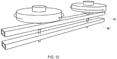
- the holes 40' of the first rail 4b' and the holes 40" of the second rail 4b" are coaxial. Therefore, as shown in Figure 12 , when the shaft 114 is received by the lower rails 4b', 4b", the central pin 34 passes through one of the holes 40' in the first rail 4b' and is subsequently received by the corresponding hole 40" in the second rail 4b", at which point the outer sleeve 36 is received by the hole 40' of the first rail 4b'. The outer sleeve 36 contacts the first rail 4b' and the central pin 34 contacts the second rail 4b" to form electrical connections therewith. The first and second rails 4b', 4b" are thus able to carry the current generated in the generator 8 to which the shaft 114 is connected.
- the shaft 114 is solid along its length.
- the shaft 114 is therefore stronger than conventional shafts which must be hollow to allow wires to pass therethrough.
- the shaft 114 can therefore be manufactured from lighter materials, such as aluminium.
- Figure 13 shows an arrangement which may be used to aid the electrical connection and to provide a mechanical connection between the shaft 114 and the rails 4b', 4b".
- blocks 42 retention members
- the blocks 42 have a cross-section which corresponds to that of the rails 4b', 4b" and thus in the present example are cuboid in shape.
- the blocks 42 are sized slightly smaller than the internal cavity of the rails 4b' 4b" such that they are loose when placed within the cavity.
- the blocks 42 are provided with holes 44', 44" which correspond to the holes 40', 40" of the respective rail 4b' 4b".
- a pair of threaded holes 46 are provided in each of the blocks 42.
- the threaded holes 46 are provided on the front (or rear) surface of the blocks 42 such that they are perpendicular to the holes 44', 44".
- Complementary holes 48', 48" are provided in a front surface of the rail 4b', 4b", such that a threaded fastener 50 (a bolt or the like) can be passed through the holes 48', 48" and received by the threaded holes 46 of the blocks 42, with the holes 44', 44" of the blocks 42 aligned with the holes 40', 40" of the rails 4b', 4b".
- the blocks 42 are loose within the rails 4b', 4b" such that the threaded fasteners draw the blocks 42 towards the front surface of the rails 4b', 4b".
- This action locks the central pin 34 and outer sleeve 36 of the shaft 114 against the rail 4b', 4b" (between one wall of the holes 44', 44" in the blocks 42, and the opposite walls of the holes 40', 40" in the rails 4b', 4b") forming a solid mechanical and electrical connection.
- the blocks 42 may be electrically conductive to further aid the electrical connections between the shaft 114 and the rails 4b', 4b".
- the shaft 114 may be secured using different forms of retention member.
- a bolt may pass through the walls of the rails 4b', 4b" into a hole in the shaft 114 or simply against the outer surface of the shaft 114.
- the structure of the shaft 114 described above comprising two mutually isolated conductors, would be useful in carrying single phase AC from a suitably designed stator to an external conductive clamping/support mechanism for example of the type described above.
- the same design of shaft could be used to carry DC, for example from rectifiers within the generator.
- a plurality of generators may feed DC current or AC current (if suitably synchronised) into the lower rails which act as busbars to convey the electricity.
- This frame of the apparatus may be supplied and installed prior to fitting any of the modules 2.
- the design of the shaft 114 allows such a frame to be populated with wind turbine modules 2 in a very rapid and efficient manner, without any wiring connections whatsoever being made between the generators 8 and any other part of the system, and with no wiring being required within, nor running along, the frame.
- the shaft 114 and its constituent elements need not be circular in cross-section.
- the shaft 114 may have a square cross-section which may prevent rotation of the shaft 114.
- the two conductors of the shaft 114 have been described as being located one within the other, it will be appreciated that other arrangements may be used where the conductors (terminal portions) are provided in other positions, but still mutually isolated from one another.
- the conductors may each have complementary semi-circular cross-sections.
- the central pin 34 may have the same outer diameter as the outer sleeve 36 over the portion extending below the sleeve 36 (for example, with a ring of insulating material or an air gap between the radial surfaces of the central pin 34 and the sleeve 36).
- the holes in each of the rails 4b', 4b" may therefore have the same diameter.
- the concepts may also be extended to radial-flux generators.
- the generator need not be provided at the bottom of the module and may instead be at the top of the module or a generator provided at either end.
- the wind turbine module may be arranged such that the blade portion has its axis of rotation oriented horizontally, but perpendicular to the wind direction such that the generator is at either or both sides. Consequently, references to relative positions (e.g. "below” and the like) should be construed accordingly.
- EP16808749.2 is a European regional phase application originating from PCT/GB2016/053750 .
- the original claims of PCT/GB2016/053750 are presented as statements below so that the subject-matter of those claims is included in its entirety in the present application.
- a wind turbine apparatus comprising:
- Statement 3 The wind turbine apparatus of statements 2, wherein the connection between the yoke and the rotor is disposed between the supporting rail and the magnets and coils.
- Statement 4 The wind turbine apparatus of statement 2 or 3, wherein the rotor is rotatably mounted on the stator by a bearing, wherein the connection between the yoke and the rotor is formed around the bearing.
- a wind turbine apparatus comprising:
- Statement 9 The wind turbine apparatus of statement 8, wherein the holes in the first and second conductive rails have complementary cross-sections to the first and second terminal portions.
- Statement 10 The wind turbine apparatus of statement 8 or 9, wherein the first terminal portion is formed by a pin and the second terminal portion is formed by a sleeve which surrounds the pin; wherein the pin projects from the sleeve such that the pin is received by the second conductive rail when the sleeve is received by the first conductive rail.
- Statement 11 The wind turbine apparatus of statement 10, wherein the pin and sleeve are concentric.
- Statement 12 The wind turbine apparatus of statement 10 or 11, wherein the sleeve has a first diameter and the pin has a second diameter which is smaller than the first diameter; wherein the openings of the first and second rails are sized to receive the first and second diameters respectively.
- Statement 13 The wind turbine apparatus of any of statements 8 to 12, wherein the first and/or second rail is provided with a retention member having or defining a hole sized to receive the first or second terminal portion, wherein the retention member is configured to be aligned with the rail so that the terminal portion is received by the hole of the retention member and the opening in the rail and wherein the retention member is translatable relative to the rail so as to draw the terminal portion against the rail, thereby mechanically connecting the stator to the rail.
- Statement 14 The wind turbine apparatus of statement 13, wherein the first and/or second rails are tubular defining a cavity which extends therethrough and wherein the retention member is received within the cavity.
- Statement 15 The wind turbine apparatus of statement 14, wherein an exterior profile of the retention member is sized and/or shaped to ensure alignment of the hole of the retention member and the opening in the rail.
- Statement 16 The wind turbine apparatus of statement 15, wherein the exterior profile of the retention member substantially corresponds to an interior profile of the cavity.
- Statement 17 The wind turbine apparatus of any of statements 13 to 16, wherein the retention member is secured to the rail by a threaded fastener which translates the retention member relative to the rail as it is rotated.
Landscapes
- Engineering & Computer Science (AREA)
- Life Sciences & Earth Sciences (AREA)
- Sustainable Development (AREA)
- Sustainable Energy (AREA)
- Mechanical Engineering (AREA)
- Combustion & Propulsion (AREA)
- Chemical & Material Sciences (AREA)
- General Engineering & Computer Science (AREA)
- Power Engineering (AREA)
- Wind Motors (AREA)
- Connection Of Motors, Electrical Generators, Mechanical Devices, And The Like (AREA)
- Permanent Magnet Type Synchronous Machine (AREA)
- Motor Or Generator Frames (AREA)
Abstract
Description
- The invention relates wind turbine apparatuses and particularly, but not exclusively to wind turbine apparatuses comprising a plurality of turbine modules.
- It is known to arrange a plurality of vertical axis wind turbine (VAWT) modules within a frame to form a wind fence; see UK Patent No.
2476126 Figure 1 . As shown, theframe 1 is formed by upper and lowerstructural rails right side members wind turbine modules 7a-7d are located within theframe 1 and are spaced from one another along the width of theframe 1. Themodules 7a-7d are affixed at either end to the upper and lowerstructural rails module 7a-7d comprises a blade portion 9 and agenerator 11 coupled thereto. -
Figures 2 and 3 show an exemplary axial-flux generator 11 in further detail. As shown, thegenerator 11 comprises arotor 13 and astator 15. Therotor 13 is formed by an outer housing of thegenerator 11 which is connected to the blade portion 9 for rotation therewith. In contrast, thestator 15 is formed by ashaft 17 which is affixed to thelower rail 3b. Therotor 13 is rotatably mounted to theshaft 17 by upper andlower bearings shaft 17 carries adisc 19 which has a plurality ofcoils 23 arranged in a circle. Therotor 13 carries a plurality ofpermanent magnets 25. Thepermanent magnets 25 are arranged in an upper circle and a lower circle which correspond with the circle ofcoils 23. Thecoils 23 are sandwiched between the upper and lower sets ofmagnets 25 with a small gap therebetween to allow free movement of themagnets 25 relative to thecoils 23. - Rotation of the blade portion 9 in response to the force of wind causes rotation of the
rotor 13. The movement of themagnets 25 relative to thecoils 23 induces a current in thecoils 23 which can be harnessed as useful electricity. - As described above, the
rotor 13 is supported by a pair ofbearings rotor 13 and thestator 15 such that the distance between thecoils 23 andmagnets 25 can be minimised, thereby improving efficiency. While such an arrangement addresses axial misalignment issues between therotor 13 andstator 15, in order for the blade portion 9 androtor 13 to rotate freely, the centre of the bearing supporting the upper end of the blade portion 9 (at theupper rail 3a) must lie on the axis defined by the centres of the twobearings generator 11. With this arrangement, sufficient alignment must be achieved in manufacture/assembly, and in all weather conditions during operation, to avoid the risk that at least some of these bearings bind, thus reducing system power output, and potentially causing excessive bearing wear or overheating. Achieving and maintaining such alignment is likely to lead to an excessive requirement for frame rigidity, blade stiffness, and/or a substantial common central shaft running the full height of the module, all with significant associated cost and weight penalties. - A flexible coupling between the blade portion 9 and the
rotor 13 may be introduced to allow the rotation axis of the blade portion 9 to deviate slightly from that of thegenerator 11 without damaging either component. Such an arrangement can, however, create a new issue in that a high torque (perpendicular to the rotation axis) is generated on thelower rail 3b which supports thegenerator 11. - Moreover, in order to carry the generated current away from the
coils 23, it is necessary for theshaft 17 to be hollow so that suitable wiring can pass through theshaft 17. However, as described, theshaft 17 carries the weight of thegenerator 11 and must withstand in-service loads. As a result, such shafts are conventionally constructed from relatively high strength steel so as to give them the necessary strength and rigidity. - It is desirable to provide improved arrangements which address some or all of the issues associated with the prior art arrangements described above.
- In accordance with an aspect of the invention, there is provided a wind turbine apparatus comprising: a blade portion; a generator comprising a stator having a plurality of coils and a rotor having a plurality of magnets, the rotor being connected to the blade portion such that rotation of the blade portion and rotor generates a current within the coils; wherein the blade portion is connected to the rotor by a yoke which extends around the generator and is connected to the base of the rotor such that the magnets of the rotor and the coils of the stator are disposed between the blade portion and the connection between the yoke and the rotor.
- The stator may comprise a shaft which is received by a supporting rail.
- The connection between the yoke and the rotor may be disposed between the supporting rail and the magnets and coils.
- The rotor may be rotatably mounted on the stator by a bearing, and the connection between the yoke and the rotor may be formed around the bearing.
- The yoke may be compliant so as to allow the rotation axes of the blade portion and the rotor to be offset from one another.
- The yoke may be connected to the blade portion and/or the rotor via a compliant coupling so as to allow the rotation axes of the blade portion and the rotor to be offset from one another.
- The yoke may be connected to the blade portion and/or the generator via a quick-release mechanism.
- In accordance with another aspect of the invention, there is provided a wind turbine apparatus comprising: a blade portion; a generator comprising a stator having a plurality of coils and a rotor having a plurality of magnets, the rotor being connected to the blade portion such that rotation of the blade portion and the rotor generates a current within the coils; wherein the stator comprises a shaft, the shaft having a first terminal portion and a second terminal portion separated from one another by an insulator, the first and second terminal portions being electrically connected to the coils; wherein the shaft is received by openings provided in first and second conductive rails so as to support the generator and blade portion and such that the first and second terminal portions are electrically coupled to the first and second conductive rails respectively to carry the current from the coils.
- The holes in the first and second conductive rails may have complementary cross-sections to the first and second terminal portions.
- The first terminal portion may be formed by a pin and the second terminal portion may be formed by a sleeve which surrounds the pin. The pin may project from the sleeve such that the pin is received by the second conductive rail when the sleeve is received by the first conductive rail.
- The pin and sleeve may be concentric.
- The sleeve may have a first diameter and the pin may have a second diameter which is smaller than the first diameter. The openings of the first and second rails may be sized to receive the first and second diameters respectively.
- The first and/or second rail may be provided with a retention member having or defining a hole sized to receive the first or second terminal portion. The retention member may be configured to be aligned with the rail so that the terminal portion is received by the hole of the retention member and the opening in the rail and wherein the retention member is translatable relative to the rail so as to draw the terminal portion against the rail, thereby mechanically connecting the stator to the rail.
- The first and/or second rails may be tubular defining a cavity which extends therethrough and the retention member may be received within the cavity.
- An exterior profile of the retention member may be sized and/or shaped to ensure alignment of the hole of the retention member and the opening in the rail.
- The exterior profile of the retention member may substantially correspond to (although may fit fairly loosely within) an interior profile of the cavity.
- The retention member may be secured to the rail by a threaded fastener which translates the retention member relative to the rail as it is rotated.
- The blade portion and the generator may form a turbine module and the apparatus may comprise a plurality of said modules.
- For a better understanding of the invention, and to show more clearly how it may be carried into effect, reference will now be made, by way of example, to the accompanying drawings, in which:-
-
Figure 1 is a front view of a prior art wind fence; -
Figure 2 is a front view of a prior art generator; -
Figure 3 is a cross-sectional view of the generator ofFigure 2 ; -
Figure 4 is a cross-sectional view of a wind turbine module according to an embodiment of the invention; -
Figure 5 is a cross-sectional view of a wind turbine module according to another embodiment of the invention; -
Figure 6 is a perspective view of the wind turbine module ofFigure 4 showing a yoke arrangement; -
Figure 7 is a perspective view of the wind turbine module ofFigure 4 following engagement with a lower rail; -
Figure 8 is a perspective view of a generator according to an embodiment of the invention; -
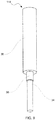
Figure 9 is a perspective view of a shaft of the generator; -
Figure 10 is a cross-sectional view of the shaft; -
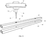
Figure 11 is a perspective view showing the generator prior to engagement with a pair of conductive rails; -
Figure 12 is a perspective view showing a pair of generators engaged with the conductive rails; and -
Figure 13 is an exploded view showing a mechanical connection between the generator and the conductive rails. -
Figure 4 shows awind turbine module 2 according to an embodiment of the invention. Themodule 2 may be one of a plurality of similar modules arranged in a frame comprising anupper rail 4a and alower rail 4b, in a similar manner to that shown inFigure 1 . - The
module 2 is connected at its upper end to theupper rail 4a and at its lower end to thelower rail 4b. Themodule 2 comprises ablade portion 6 and agenerator 8. Thegenerator 8 is an axial-flux generator which comprises arotor 10 and astator 12. Therotor 10 is formed by an outer housing of thegenerator 8 which is connected to theblade portion 6 for rotation therewith. In contrast, thestator 12 is formed by ashaft 14 which is affixed to thelower rail 4b. Therotor 10 is rotatably mounted to theshaft 14 by upper andlower bearings shaft 14 carries adisc 18 which has a plurality ofcoils 20 arranged in a circle. Therotor 10 carries a plurality ofpermanent magnets 22. Thepermanent magnets 22 are arranged in an upper circle and a lower circle which correspond with the circle ofcoils 20. Thecoils 20 are sandwiched between the upper and lower sets of themagnets 22 with a small gap therebetween to allow free movement of themagnets 22 relative to thecoils 20. - The
blade portion 6 is connected to therotor 10 by ayoke 24 which extends from theblade portion 6 to a lower side of therotor 10. Specifically, theyoke 24 connects to therotor 10 around thelower bearing 16b. Theyoke 24 thus connects to therotor 10 below thedisc 18 of thestator 12 and itscoils 20 and below themagnets 22 of therotor 10 itself. - In contrast to prior art arrangements where the blade portion is connected directly to the rotor (i.e. either rigidly or flexibly to the top of the rotor), the
yoke 24 allows the connection to therotor 10 to be placed lower down, closer to thelower rail 4b. The distance x between the coupling point and the neutral axis of therail 4b in thus minimized. This reduces the levering effect of the wind loading on therail 4b, via therotor 10 orshaft 14, and thus minimises misalignment between the axes of rotation of theblade portion 6 and therotor 10 for a given wind loading. - Further, as shown in
Figure 5 , the height of thegenerator 8 has no effect on the distance x such that stacked stator configurations can be used without increasing the levering effect. - It will be appreciated that the structure of the
yoke 24 may take various forms, provided that it places the coupling point below thedisc 18 of thestator 12 and itscoils 20 and below themagnets 22 of therotor 10 itself. However,Figures 6 and7 show anexemplary yoke 24. - As shown in
Figures 6 and7 , theyoke 24 is formed as a metal band which is connected at either end to the base of theblade portion 6 such that it extends across the span (i.e. the width of theblade portion 6 when aligned with the frame) of theblade portion 6. Between each end, the band is bent away from theblade portion 6 to form acentral section 26. Thecentral section 26 is spaced from theblade portion 6 by a distance which is sufficient to receive thegenerator 8. Thecentral section 26 comprises a hole which is received about ahub 28 formed at the base of the outer housing of therotor 10. The diameter of the hole in thecentral section 26 of theyoke 24 is slightly larger than the external diameter of thehub 28 such that it fits loosely around thehub 28. Thecentral section 26 is retained on thehub 28 by alower collar 30 which is connected to the distal end of thehub 28. A plurality ofelastomeric washers 32 are disposed on the upper and lower sides of thecentral section 26 between thecentral section 26 and a lower radial surface of therotor 10 and between thecentral section 26 and thecollar 30. Theelastomeric washers 32 provide a compliant coupling between theblade portion 6 and therotor 10 allow their orientations to vary under wind loading. A similar compliance may also be provided using other forms of flexible mounting, such as o-rings, springs, flexible struts or pillars. Theyoke 24 may also be formed from flexible materials (e.g. polymers, glass reinforced composites, or aluminium or sheet steel) and/or articulated joints may be provided within theyoke 24 itself to provide compliance. - The
yoke 24 may be detachable from theblade portion 6 and/or therotor 10 using conventional bolts or quick release catches. This may allow theblade portion 6 and/or thegenerator 8 to be removed easily for maintenance or replacement. Alternatively, theentire module 2 may be removable using suitable brackets which attach to the frame. - As an illustration, an axial flux generator, constructed to match the output of a turbine with a swept area of ∼0.75m2, was mounted in a frame consisting of rectangular cross-section aluminium tubing, of cross-sectional outer dimensions 50mmx25mm. The top of the generator had a height of ∼65mm above the neutral axis of the frame member, which thus corresponded to the minimum distance for a conventional coupling arrangement. In contrast, by using the
yoke 24 described previously, theblade portion 6 can be attached between the generator and thelower rail 4b, at a distance of -9mm from the surface of the beam, or <22mm from its neutral axis, corresponding to a reduction in torque (and hence tendency to twist) on the box-section frame member, of approximately 66%. - An embodiment of the shaft will now be described with reference to
Figures 8 to 13 . Theshaft 114 shown therein may be used with the yoke arrangement described previously or may be used with conventional modules. - The
shaft 114 comprises a central pin orrod 34 and anouter sleeve 36 within which thecentral pin 34 is disposed (seeFigure 10 ). - The
central pin 34 is cylindrical and substantially solid along its length. Theouter sleeve 36 is tubular and has an internal diameter which is sized to receive thecentral pin 34 such that thecentral pin 34 andouter sleeve 36 are arranged concentrically. As shown, thecentral pin 34 has a greater axial length than theouter sleeve 36 such that a portion of thecentral pin 34 extends out of theouter sleeve 36. Both thecentral pin 34 and outer sleeve 36 (or at least a part thereof) are formed from conductive metals. For example, a medium/high strength aluminium alloy may be used, but other shaft materials including, but not limited to, copper, brass or steel may also be used. - Disposed between the
central pin 34 and theouter sleeve 36 is an insulatinglayer 38. The insulatinglayer 38 may be a discrete tubular element disposed between thecentral pin 34 andouter sleeve 36 or may be a layer formed on either (or both) of (or between) thecentral pin 34 and theouter sleeve 36. The insulatinglayer 38 extends along at least the axial length of theouter sleeve 36 and electrically insulates thecentral pin 34 from theouter sleeve 36. The insulatinglayer 38 may be a reinforced thermoplastic or thermoset material, such as a fibre-reinforced epoxy material, with the three components being bonded together, for example using an epoxy adhesive, to form a composite unit. - The
central pin 34 andouter sleeve 36 are connected to either end of thecoils 20 to form connector terminals. Thecentral pin 34 andouter sleeve 36 may be connected to thecoils 20 either directly to provide an AC output or indirectly via a rectifier circuit to provide a DC output. Where a DC output is used, the connector terminals form positive and negative terminals. - As shown in
Figure 11 , thelower rail 4b is divided into a first (upper)lower rail 4b' and a second (lower)rail 4b". Eachrail 4b', 4b" is formed by a hollow electrically conductive, structural box-section beam. Therails 4b', 4b" may be mechanically linked to one another with electrically insulating tie-pieces (not shown). - The first
lower rail 4b' is provided with a plurality of holes 40' spaced along its length (two are shown, but any number may be provided to match the number of modules 2). The holes 40' are in fact each formed as a pair of coaxial holes in the upper and lower walls of the beam structure. The holes 40' have an internal diameter which is sized to receive (i.e. is slightly larger than) theouter sleeve 36 of theshaft 114. Similarly, thesecond rail 4b" is provided with a plurality ofholes 40" spaced along its length and sized to receive thecentral pin 34. Theholes 40" of thesecond rail 4b" thus have a smaller diameter compared to the holes 40'. - The holes 40' of the
first rail 4b' and theholes 40" of thesecond rail 4b" are coaxial. Therefore, as shown inFigure 12 , when theshaft 114 is received by thelower rails 4b', 4b", thecentral pin 34 passes through one of the holes 40' in thefirst rail 4b' and is subsequently received by the correspondinghole 40" in thesecond rail 4b", at which point theouter sleeve 36 is received by the hole 40' of thefirst rail 4b'. Theouter sleeve 36 contacts thefirst rail 4b' and thecentral pin 34 contacts thesecond rail 4b" to form electrical connections therewith. The first andsecond rails 4b', 4b" are thus able to carry the current generated in thegenerator 8 to which theshaft 114 is connected. - As described, the
shaft 114 is solid along its length. Theshaft 114 is therefore stronger than conventional shafts which must be hollow to allow wires to pass therethrough. Theshaft 114 can therefore be manufactured from lighter materials, such as aluminium. -
Figure 13 shows an arrangement which may be used to aid the electrical connection and to provide a mechanical connection between theshaft 114 and therails 4b', 4b". Specifically, as shown, blocks 42 (retention members) may be disposed within therails 4b' 4b". Theblocks 42 have a cross-section which corresponds to that of therails 4b', 4b" and thus in the present example are cuboid in shape. Theblocks 42 are sized slightly smaller than the internal cavity of therails 4b' 4b" such that they are loose when placed within the cavity. - The
blocks 42 are provided withholes 44', 44" which correspond to theholes 40', 40" of therespective rail 4b' 4b". A pair of threadedholes 46 are provided in each of theblocks 42. The threaded holes 46 are provided on the front (or rear) surface of theblocks 42 such that they are perpendicular to theholes 44', 44".Complementary holes 48', 48" are provided in a front surface of therail 4b', 4b", such that a threaded fastener 50 (a bolt or the like) can be passed through theholes 48', 48" and received by the threadedholes 46 of theblocks 42, with theholes 44', 44" of theblocks 42 aligned with theholes 40', 40" of therails 4b', 4b". As described previously, theblocks 42 are loose within therails 4b', 4b" such that the threaded fasteners draw theblocks 42 towards the front surface of therails 4b', 4b". This action locks thecentral pin 34 andouter sleeve 36 of theshaft 114 against therail 4b', 4b" (between one wall of theholes 44', 44" in theblocks 42, and the opposite walls of theholes 40', 40" in therails 4b', 4b") forming a solid mechanical and electrical connection. Theblocks 42 may be electrically conductive to further aid the electrical connections between theshaft 114 and therails 4b', 4b". - The
shaft 114 may be secured using different forms of retention member. For example, a bolt may pass through the walls of therails 4b', 4b" into a hole in theshaft 114 or simply against the outer surface of theshaft 114. - From an electrical perspective, the structure of the
shaft 114 described above, comprising two mutually isolated conductors, would be useful in carrying single phase AC from a suitably designed stator to an external conductive clamping/support mechanism for example of the type described above. Alternatively, the same design of shaft could be used to carry DC, for example from rectifiers within the generator. - Other variants on the above shaft design could be used, for example, to carry 3 phase AC, by the construction of a 5 layer shaft of alternating concentric conductors and insulating layers to a support structure comprising, for example, three electrically conductive rails, one above the other, with corresponding holes to receive the 3 mutually isolated electrically conductive concentric tubes/cylinders of such a shaft.
- A plurality of generators may feed DC current or AC current (if suitably synchronised) into the lower rails which act as busbars to convey the electricity.
- This frame of the apparatus may be supplied and installed prior to fitting any of the
modules 2. The design of theshaft 114 allows such a frame to be populated withwind turbine modules 2 in a very rapid and efficient manner, without any wiring connections whatsoever being made between thegenerators 8 and any other part of the system, and with no wiring being required within, nor running along, the frame. - The
shaft 114 and its constituent elements need not be circular in cross-section. For example, theshaft 114 may have a square cross-section which may prevent rotation of theshaft 114. Further, although the two conductors of theshaft 114 have been described as being located one within the other, it will be appreciated that other arrangements may be used where the conductors (terminal portions) are provided in other positions, but still mutually isolated from one another. For example, the conductors may each have complementary semi-circular cross-sections. Further, thecentral pin 34 may have the same outer diameter as theouter sleeve 36 over the portion extending below the sleeve 36 (for example, with a ring of insulating material or an air gap between the radial surfaces of thecentral pin 34 and the sleeve 36). The holes in each of therails 4b', 4b" may therefore have the same diameter. - Further, although the aspects described previously are particularly beneficial for an apparatus comprising a plurality of wind turbine modules, they may also be used with an apparatus comprising a single turbine.
- The above description focuses on axial-flux generators; however, it will be appreciated that the concepts may also be extended to radial-flux generators. Further, the generator need not be provided at the bottom of the module and may instead be at the top of the module or a generator provided at either end. Moreover, the wind turbine module may be arranged such that the blade portion has its axis of rotation oriented horizontally, but perpendicular to the wind direction such that the generator is at either or both sides. Consequently, references to relative positions (e.g. "below" and the like) should be construed accordingly.
- To avoid unnecessary duplication of effort and repetition of text in the specification, certain features are described in relation to only one or several aspects or embodiments of the invention. However, it is to be understood that, where it is technically possible, features described in relation to any aspect or embodiment of the invention may also be used with any other aspect or embodiment of the invention.
- The invention is not limited to the embodiments described herein, and may be modified or adapted without departing from the scope of the present invention.
- The present application is a divisional application of
EP16808749.2 EP16808749.2 PCT/GB2016/053750 PCT/GB2016/053750 -
Statement 1. A wind turbine apparatus comprising: - a blade portion;
- a generator comprising a stator having a plurality of coils and a rotor having a plurality of magnets, the rotor being connected to the blade portion such that rotation of the blade portion and rotor generates a current within the coils;
- wherein the blade portion is connected to the rotor by a yoke which extends around the generator and is connected to the base of the rotor such that the magnets of the rotor and the coils of the stator are disposed between the blade portion and the connection between the yoke and the rotor.
-
Statement 2. The wind turbine apparatus ofstatement 1, wherein the stator comprises a shaft which is received by a supporting rail. - Statement 3. The wind turbine apparatus of
statements 2, wherein the connection between the yoke and the rotor is disposed between the supporting rail and the magnets and coils. - Statement 4. The wind turbine apparatus of
statement 2 or 3, wherein the rotor is rotatably mounted on the stator by a bearing, wherein the connection between the yoke and the rotor is formed around the bearing. - Statement 5. The wind turbine apparatus of any preceding statement, wherein the yoke is compliant so as to allow the rotation axes of the blade portion and the rotor to be offset from one another.
-
Statement 6. The wind turbine apparatus of any preceding statement, wherein the yoke is connected to the blade portion and/or the rotor via a compliant coupling so as to allow the rotation axes of the blade portion and the rotor to be offset from one another. - Statement 7. The wind turbine apparatus of any preceding statement, wherein the yoke is connected to the blade portion and/or the generator via a quick-release mechanism.
-
Statement 8. A wind turbine apparatus comprising: - a blade portion;
- a generator comprising a stator having a plurality of coils and a rotor having a plurality of magnets, the rotor being connected to the blade portion such that rotation of the blade portion and the rotor generates a current within the coils;
- wherein the stator comprises a shaft, the shaft having a first terminal portion and a second terminal portion separated from one another by an insulator, the first and second terminal portions being electrically connected to the coils;
- wherein the shaft is received by openings provided in first and second conductive rails so as to support the generator and blade portion and such that the first and second terminal portions are electrically coupled to the first and second conductive rails respectively to carry the current from the coils.
- Statement 9. The wind turbine apparatus of
statement 8, wherein the holes in the first and second conductive rails have complementary cross-sections to the first and second terminal portions. -
Statement 10. The wind turbine apparatus ofstatement 8 or 9, wherein the first terminal portion is formed by a pin and the second terminal portion is formed by a sleeve which surrounds the pin; wherein the pin projects from the sleeve such that the pin is received by the second conductive rail when the sleeve is received by the first conductive rail. -
Statement 11. The wind turbine apparatus ofstatement 10, wherein the pin and sleeve are concentric. -
Statement 12. The wind turbine apparatus ofstatement -
Statement 13. The wind turbine apparatus of any ofstatements 8 to 12, wherein the first and/or second rail is provided with a retention member having or defining a hole sized to receive the first or second terminal portion, wherein the retention member is configured to be aligned with the rail so that the terminal portion is received by the hole of the retention member and the opening in the rail and wherein the retention member is translatable relative to the rail so as to draw the terminal portion against the rail, thereby mechanically connecting the stator to the rail. -
Statement 14. The wind turbine apparatus ofstatement 13, wherein the first and/or second rails are tubular defining a cavity which extends therethrough and wherein the retention member is received within the cavity. -
Statement 15. The wind turbine apparatus ofstatement 14, wherein an exterior profile of the retention member is sized and/or shaped to ensure alignment of the hole of the retention member and the opening in the rail. - Statement 16. The wind turbine apparatus of
statement 15, wherein the exterior profile of the retention member substantially corresponds to an interior profile of the cavity. -
Statement 17. The wind turbine apparatus of any ofstatements 13 to 16, wherein the retention member is secured to the rail by a threaded fastener which translates the retention member relative to the rail as it is rotated. -
Statement 18. The wind turbine apparatus of any preceding statement, wherein the blade portion and the generator form a turbine module and wherein the apparatus comprises a plurality of said modules. -
Statement 19. The wind turbine apparatus substantially as described herein with reference to and as shown in the accompanying drawings.
Claims (6)
- A wind turbine apparatus comprising:a blade portion;a generator comprising a stator having a plurality of coils and a rotor having a plurality of magnets, the rotor being connected to the blade portion such that rotation of the blade portion and rotor generates a current within the coils;wherein the blade portion is connected to the rotor by a yoke which extends around the generator and is connected to the base of the rotor such that the magnets of the rotor and the coils of the stator are disposed between the blade portion and the connection between the yoke and the rotor,wherein the stator comprises a shaft which is received by a supporting rail, andwherein the connection between the yoke and the rotor is disposed between the supporting rail and the magnets and coils.
- A wind turbine apparatus as claimed in claim 1, wherein the rotor is rotatably mounted on the stator by a bearing, wherein the connection between the yoke and the rotor is formed around the bearing.
- A wind turbine apparatus as claimed in any preceding claim, wherein the yoke is compliant so as to allow the rotation axes of the blade portion and the rotor to be offset from one another.
- A wind turbine apparatus as claimed in any preceding claim, wherein the yoke is connected to the blade portion and/or the rotor via a compliant coupling so as to allow the rotation axes of the blade portion and the rotor to be offset from one another.
- A wind turbine apparatus as claimed in any preceding claim, wherein the yoke is connected to the blade portion and/or the generator via a quick-release mechanism.
- A wind turbine apparatus as claimed in any preceding claim, wherein the blade portion and the generator form a turbine module and wherein the apparatus comprises a plurality of said modules.
Applications Claiming Priority (3)
| Application Number | Priority Date | Filing Date | Title |
|---|---|---|---|
| GB1521927.2A GB2545416B (en) | 2015-12-12 | 2015-12-12 | Wind turbine apparatuses |
| PCT/GB2016/053750 WO2017098212A2 (en) | 2015-12-12 | 2016-11-30 | Wind turbine apparatuses |
| EP16808749.2A EP3387252B1 (en) | 2015-12-12 | 2016-11-30 | Wind turbine apparatuses |
Related Parent Applications (2)
| Application Number | Title | Priority Date | Filing Date |
|---|---|---|---|
| EP16808749.2A Division-Into EP3387252B1 (en) | 2015-12-12 | 2016-11-30 | Wind turbine apparatuses |
| EP16808749.2A Division EP3387252B1 (en) | 2015-12-12 | 2016-11-30 | Wind turbine apparatuses |
Publications (2)
| Publication Number | Publication Date |
|---|---|
| EP3486478A1 true EP3486478A1 (en) | 2019-05-22 |
| EP3486478B1 EP3486478B1 (en) | 2020-07-29 |
Family
ID=55274627
Family Applications (2)
| Application Number | Title | Priority Date | Filing Date |
|---|---|---|---|
| EP16808749.2A Active EP3387252B1 (en) | 2015-12-12 | 2016-11-30 | Wind turbine apparatuses |
| EP18215972.3A Active EP3486478B1 (en) | 2015-12-12 | 2016-11-30 | Wind turbine apparatus |
Family Applications Before (1)
| Application Number | Title | Priority Date | Filing Date |
|---|---|---|---|
| EP16808749.2A Active EP3387252B1 (en) | 2015-12-12 | 2016-11-30 | Wind turbine apparatuses |
Country Status (11)
| Country | Link |
|---|---|
| US (1) | US10871147B2 (en) |
| EP (2) | EP3387252B1 (en) |
| JP (2) | JP6653980B2 (en) |
| CN (2) | CN110645143B (en) |
| AU (2) | AU2016366631B2 (en) |
| CA (2) | CA3007044C (en) |
| CL (1) | CL2018001540A1 (en) |
| GB (2) | GB2545416B (en) |
| NZ (1) | NZ743188A (en) |
| WO (1) | WO2017098212A2 (en) |
| ZA (2) | ZA201803503B (en) |
Cited By (1)
| Publication number | Priority date | Publication date | Assignee | Title |
|---|---|---|---|---|
| CN114651125A (en) * | 2019-12-11 | 2022-06-21 | 瓦奇拉·普蒂查姆 | Shaftless horizontal axis wind turbine |
Families Citing this family (1)
| Publication number | Priority date | Publication date | Assignee | Title |
|---|---|---|---|---|
| GB2602337A (en) | 2020-12-23 | 2022-06-29 | Larkfleet Smart Homes Ltd | Electrical system for a residential site |
Citations (5)
| Publication number | Priority date | Publication date | Assignee | Title |
|---|---|---|---|---|
| DE4005685A1 (en) * | 1990-02-23 | 1991-12-12 | Erich Herter | Vertical wind turbine driving electrical ring generators - has rotor supported from mast by relatively small pendulum bearing |
| DE4006256A1 (en) * | 1990-02-23 | 1992-02-27 | Erich Herter | Wind turbine for electricity generation - has vertical rotor used for direct drive of ring generator |
| DE4007017A1 (en) * | 1990-02-28 | 1992-05-07 | Erich Herter | Axial-flow wind turbine with independent stator rings - which brake and stop individual free-running stator supports for safety of continuous operation in gale |
| GB2461285A (en) * | 2008-06-26 | 2009-12-30 | Converteam Technology Ltd | Vertical axis wind turbine |
| GB2476126A (en) | 2009-12-12 | 2011-06-15 | Giles Henry Rodway | Interconnected modular wind turbine array |
Family Cites Families (30)
| Publication number | Priority date | Publication date | Assignee | Title |
|---|---|---|---|---|
| US3556229A (en) * | 1968-08-12 | 1971-01-19 | Hawkins Mfg Inc | Replaceable blade combination for duckfoot chisel |
| FR2295257A1 (en) * | 1974-12-16 | 1976-07-16 | Bonomi Frederic | Wind driven generator with twin vertical cylindrical rotors - having surfaces deformed by wind pressure to form blades |
| JPH09233763A (en) * | 1996-02-28 | 1997-09-05 | Shinko Electric Co Ltd | Device for simultaneously rotating concentric twin shafts |
| JP3756437B2 (en) | 2000-09-22 | 2006-03-15 | 大本 正子 | Wind turbine blade for wind power generation and unit and apparatus using the same |
| GB2402976B (en) * | 2003-06-05 | 2006-09-27 | Intec Power Systems Ltd | Generator |
| EP1731760A1 (en) | 2004-03-31 | 2006-12-13 | Intellectual Property Bank Corp. | Cantilevered vertical shaft type windmill |
| EP1907693A1 (en) * | 2005-07-28 | 2008-04-09 | Cleanfield Energy Corp. | Power generating system including modular wind turbine-generator assembly |
| JP4728206B2 (en) | 2006-09-29 | 2011-07-20 | 新高能源科技股▲フン▼有限公司 | Two-axis vertical axis wind turbine |
| US20090140528A1 (en) * | 2007-04-20 | 2009-06-04 | Bri Energy Solutions Limited | Wind and Updraft Turbine |
| HUP0700705A2 (en) | 2007-10-30 | 2009-10-28 | Viktor Dr Gyoergyi | Vertical axis wind turbine and power station |
| CN101539103B (en) * | 2008-04-10 | 2011-04-13 | 河南科技大学 | Stall-controllable permanent magnet wind turbine |
| CN101435412B (en) * | 2008-12-19 | 2011-08-24 | 严强 | Vertical shaft wind power generator structure |
| CN102187096A (en) * | 2009-01-07 | 2011-09-14 | 诺亚株式会社 | Fixing structure for generator shaft of wind driven generator of outer rotor coreless type |
| US9328717B1 (en) * | 2009-04-27 | 2016-05-03 | James A. Walker | Golden ratio axial flow apparatus |
| US8487470B2 (en) * | 2009-05-22 | 2013-07-16 | Derek Grassman | Vertical axis wind turbine and generator therefore |
| US8188613B2 (en) * | 2009-07-16 | 2012-05-29 | Lee S Peter | Integrated turbine generator/motor and method |
| US20110089698A1 (en) * | 2009-07-24 | 2011-04-21 | William Ahmadi | Combination solar and dual generator wind turbine |
| IT1395071B1 (en) * | 2009-08-11 | 2012-09-05 | Enatek S R L | ELECTRIC TYPE ALTERNATOR FOR WIND GENERATORS |
| US8541897B2 (en) * | 2009-09-01 | 2013-09-24 | University Of Southern California | Generation of electric energy using cable-supported windmills |
| ES2559018T3 (en) | 2010-02-17 | 2016-02-10 | Spinetic Energy Limited | Wind turbine system |
| CN103032269A (en) | 2011-10-08 | 2013-04-10 | 黄志平 | Vertical double-shaft wind power generation device |
| JP5509183B2 (en) * | 2011-11-29 | 2014-06-04 | Thk株式会社 | Vertical axis wind turbine bearing and vertical axis wind power generator |
| MY168321A (en) | 2012-01-13 | 2018-10-30 | GmbH youWINenergy | Wind turbine rotor |
| JP5620941B2 (en) * | 2012-04-26 | 2014-11-05 | Thk株式会社 | Rotating shaft device of vertical axis type fluid power generation device and vertical shaft type fluid power generation device |
| WO2014043507A1 (en) * | 2012-09-13 | 2014-03-20 | Martin Epstein | Vertical axis wind turbine with cambered airfoil blades |
| CN203130369U (en) * | 2013-01-29 | 2013-08-14 | 河南科技大学 | Vertical shaft wind wheel combined blade pitch changing wind power generating device |
| CN104632528A (en) * | 2013-11-06 | 2015-05-20 | 毕献奎 | Wind driven generator |
| US20150159628A1 (en) * | 2013-12-09 | 2015-06-11 | Kari Appa | Offshore contra rotor wind turbine system |
| CN104265571B (en) * | 2014-09-01 | 2017-01-25 | 江苏大学 | Inner rotor five-freedom-degree magnetic suspension vertical axis wind turbine |
| US10724502B2 (en) * | 2018-05-22 | 2020-07-28 | Creating Moore, Llc | Vertical axis wind turbine apparatus and system |
-
2015
- 2015-12-12 GB GB1521927.2A patent/GB2545416B/en active Active
- 2015-12-12 GB GB1701202.2A patent/GB2546635B/en active Active
-
2016
- 2016-11-30 CN CN201910750109.XA patent/CN110645143B/en active Active
- 2016-11-30 NZ NZ74318816A patent/NZ743188A/en unknown
- 2016-11-30 US US16/061,255 patent/US10871147B2/en active Active
- 2016-11-30 CA CA3007044A patent/CA3007044C/en active Active
- 2016-11-30 EP EP16808749.2A patent/EP3387252B1/en active Active
- 2016-11-30 JP JP2018529106A patent/JP6653980B2/en active Active
- 2016-11-30 CN CN201680072869.4A patent/CN108368826B/en active Active
- 2016-11-30 CA CA3048573A patent/CA3048573C/en active Active
- 2016-11-30 WO PCT/GB2016/053750 patent/WO2017098212A2/en active Application Filing
- 2016-11-30 AU AU2016366631A patent/AU2016366631B2/en active Active
- 2016-11-30 EP EP18215972.3A patent/EP3486478B1/en active Active
-
2018
- 2018-05-28 ZA ZA2018/03503A patent/ZA201803503B/en unknown
- 2018-06-08 CL CL2018001540A patent/CL2018001540A1/en unknown
- 2018-11-27 ZA ZA201808072A patent/ZA201808072B/en unknown
-
2019
- 2019-07-12 AU AU2019205022A patent/AU2019205022B2/en active Active
- 2019-09-17 JP JP2019168667A patent/JP6846488B2/en active Active
Patent Citations (5)
| Publication number | Priority date | Publication date | Assignee | Title |
|---|---|---|---|---|
| DE4005685A1 (en) * | 1990-02-23 | 1991-12-12 | Erich Herter | Vertical wind turbine driving electrical ring generators - has rotor supported from mast by relatively small pendulum bearing |
| DE4006256A1 (en) * | 1990-02-23 | 1992-02-27 | Erich Herter | Wind turbine for electricity generation - has vertical rotor used for direct drive of ring generator |
| DE4007017A1 (en) * | 1990-02-28 | 1992-05-07 | Erich Herter | Axial-flow wind turbine with independent stator rings - which brake and stop individual free-running stator supports for safety of continuous operation in gale |
| GB2461285A (en) * | 2008-06-26 | 2009-12-30 | Converteam Technology Ltd | Vertical axis wind turbine |
| GB2476126A (en) | 2009-12-12 | 2011-06-15 | Giles Henry Rodway | Interconnected modular wind turbine array |
Cited By (1)
| Publication number | Priority date | Publication date | Assignee | Title |
|---|---|---|---|---|
| CN114651125A (en) * | 2019-12-11 | 2022-06-21 | 瓦奇拉·普蒂查姆 | Shaftless horizontal axis wind turbine |
Also Published As
Similar Documents
| Publication | Publication Date | Title |
|---|---|---|
| JP5767112B2 (en) | Wind turbine rotor and wind turbine | |
| AU2019205022B2 (en) | Wind turbine apparatuses | |
| US20190348881A1 (en) | Electric generator having multiple electrical machines | |
| CN103299519A (en) | Dynamo-electric machine | |
| US20150180317A1 (en) | Rotating rectifier assembly for electric machine | |
| US20120177492A1 (en) | Wind turbine | |
| CN111386651B (en) | Stator assembly, generator and wind turbine | |
| CA2872614C (en) | Bolted connector for stator coils of an electrical generator | |
| CN105449971B (en) | A kind of compensation end line for direct current generator divides valve conjunction structure | |
| EP2713478B1 (en) | Outer structure of a generator | |
| US10760550B2 (en) | Biased segmented dual radial gap brushless PMDC motor/generator | |
| KR20090069101A (en) | Cable holder in wind generator | |
| CN114765407A (en) | Armature segment, armature and method for assembling them |
Legal Events
| Date | Code | Title | Description |
|---|---|---|---|
| PUAI | Public reference made under article 153(3) epc to a published international application that has entered the european phase |
Free format text: ORIGINAL CODE: 0009012 |
|
| STAA | Information on the status of an ep patent application or granted ep patent |
Free format text: STATUS: THE APPLICATION HAS BEEN PUBLISHED |
|
| AC | Divisional application: reference to earlier application |
Ref document number: 3387252 Country of ref document: EP Kind code of ref document: P |
|
| AK | Designated contracting states |
Kind code of ref document: A1 Designated state(s): AL AT BE BG CH CY CZ DE DK EE ES FI FR GB GR HR HU IE IS IT LI LT LU LV MC MK MT NL NO PL PT RO RS SE SI SK SM TR |
|
| STAA | Information on the status of an ep patent application or granted ep patent |
Free format text: STATUS: REQUEST FOR EXAMINATION WAS MADE |
|
| 17P | Request for examination filed |
Effective date: 20190917 |
|
| RBV | Designated contracting states (corrected) |
Designated state(s): AL AT BE BG CH CY CZ DE DK EE ES FI FR GB GR HR HU IE IS IT LI LT LU LV MC MK MT NL NO PL PT RO RS SE SI SK SM TR |
|
| GRAP | Despatch of communication of intention to grant a patent |
Free format text: ORIGINAL CODE: EPIDOSNIGR1 |
|
| STAA | Information on the status of an ep patent application or granted ep patent |
Free format text: STATUS: GRANT OF PATENT IS INTENDED |
|
| INTG | Intention to grant announced |
Effective date: 20200129 |
|
| GRAS | Grant fee paid |
Free format text: ORIGINAL CODE: EPIDOSNIGR3 |
|
| GRAA | (expected) grant |
Free format text: ORIGINAL CODE: 0009210 |
|
| STAA | Information on the status of an ep patent application or granted ep patent |
Free format text: STATUS: THE PATENT HAS BEEN GRANTED |
|
| RBV | Designated contracting states (corrected) |
Designated state(s): AL AT BE BG CH CY CZ DE DK EE ES FI FR GR HR HU IE IS IT LI LT LU LV MC MK MT NL NO PL PT RO RS SE SI SK SM TR |
|
| AC | Divisional application: reference to earlier application |
Ref document number: 3387252 Country of ref document: EP Kind code of ref document: P |
|
| AK | Designated contracting states |
Kind code of ref document: B1 Designated state(s): AL AT BE BG CH CY CZ DE DK EE ES FI FR GR HR HU IE IS IT LI LT LU LV MC MK MT NL NO PL PT RO RS SE SI SK SM TR |
|
| REG | Reference to a national code |
Ref country code: CH Ref legal event code: EP |
|
| REG | Reference to a national code |
Ref country code: DE Ref legal event code: R096 Ref document number: 602016041140 Country of ref document: DE |
|
| REG | Reference to a national code |
Ref country code: AT Ref legal event code: REF Ref document number: 1296110 Country of ref document: AT Kind code of ref document: T Effective date: 20200815 |
|
| REG | Reference to a national code |
Ref country code: IE Ref legal event code: FG4D |
|
| REG | Reference to a national code |
Ref country code: LT Ref legal event code: MG4D |
|
| REG | Reference to a national code |
Ref country code: NL Ref legal event code: MP Effective date: 20200729 |
|
| REG | Reference to a national code |
Ref country code: DE Ref legal event code: R082 Ref document number: 602016041140 Country of ref document: DE Representative=s name: HL KEMPNER PATENTANWAELTE, SOLICITORS (ENGLAND, DE Ref country code: DE Ref legal event code: R082 Ref document number: 602016041140 Country of ref document: DE Representative=s name: HL KEMPNER PATENTANWALT, RECHTSANWALT, SOLICIT, DE |
|
| REG | Reference to a national code |
Ref country code: AT Ref legal event code: MK05 Ref document number: 1296110 Country of ref document: AT Kind code of ref document: T Effective date: 20200729 |
|
| PG25 | Lapsed in a contracting state [announced via postgrant information from national office to epo] |
Ref country code: PT Free format text: LAPSE BECAUSE OF FAILURE TO SUBMIT A TRANSLATION OF THE DESCRIPTION OR TO PAY THE FEE WITHIN THE PRESCRIBED TIME-LIMIT Effective date: 20201130 Ref country code: GR Free format text: LAPSE BECAUSE OF FAILURE TO SUBMIT A TRANSLATION OF THE DESCRIPTION OR TO PAY THE FEE WITHIN THE PRESCRIBED TIME-LIMIT Effective date: 20201030 Ref country code: ES Free format text: LAPSE BECAUSE OF FAILURE TO SUBMIT A TRANSLATION OF THE DESCRIPTION OR TO PAY THE FEE WITHIN THE PRESCRIBED TIME-LIMIT Effective date: 20200729 Ref country code: LT Free format text: LAPSE BECAUSE OF FAILURE TO SUBMIT A TRANSLATION OF THE DESCRIPTION OR TO PAY THE FEE WITHIN THE PRESCRIBED TIME-LIMIT Effective date: 20200729 Ref country code: BG Free format text: LAPSE BECAUSE OF FAILURE TO SUBMIT A TRANSLATION OF THE DESCRIPTION OR TO PAY THE FEE WITHIN THE PRESCRIBED TIME-LIMIT Effective date: 20201029 Ref country code: AT Free format text: LAPSE BECAUSE OF FAILURE TO SUBMIT A TRANSLATION OF THE DESCRIPTION OR TO PAY THE FEE WITHIN THE PRESCRIBED TIME-LIMIT Effective date: 20200729 Ref country code: SE Free format text: LAPSE BECAUSE OF FAILURE TO SUBMIT A TRANSLATION OF THE DESCRIPTION OR TO PAY THE FEE WITHIN THE PRESCRIBED TIME-LIMIT Effective date: 20200729 Ref country code: NO Free format text: LAPSE BECAUSE OF FAILURE TO SUBMIT A TRANSLATION OF THE DESCRIPTION OR TO PAY THE FEE WITHIN THE PRESCRIBED TIME-LIMIT Effective date: 20201029 Ref country code: HR Free format text: LAPSE BECAUSE OF FAILURE TO SUBMIT A TRANSLATION OF THE DESCRIPTION OR TO PAY THE FEE WITHIN THE PRESCRIBED TIME-LIMIT Effective date: 20200729 Ref country code: FI Free format text: LAPSE BECAUSE OF FAILURE TO SUBMIT A TRANSLATION OF THE DESCRIPTION OR TO PAY THE FEE WITHIN THE PRESCRIBED TIME-LIMIT Effective date: 20200729 |
|
| PG25 | Lapsed in a contracting state [announced via postgrant information from national office to epo] |
Ref country code: RS Free format text: LAPSE BECAUSE OF FAILURE TO SUBMIT A TRANSLATION OF THE DESCRIPTION OR TO PAY THE FEE WITHIN THE PRESCRIBED TIME-LIMIT Effective date: 20200729 Ref country code: LV Free format text: LAPSE BECAUSE OF FAILURE TO SUBMIT A TRANSLATION OF THE DESCRIPTION OR TO PAY THE FEE WITHIN THE PRESCRIBED TIME-LIMIT Effective date: 20200729 Ref country code: PL Free format text: LAPSE BECAUSE OF FAILURE TO SUBMIT A TRANSLATION OF THE DESCRIPTION OR TO PAY THE FEE WITHIN THE PRESCRIBED TIME-LIMIT Effective date: 20200729 Ref country code: IS Free format text: LAPSE BECAUSE OF FAILURE TO SUBMIT A TRANSLATION OF THE DESCRIPTION OR TO PAY THE FEE WITHIN THE PRESCRIBED TIME-LIMIT Effective date: 20201129 |
|
| PG25 | Lapsed in a contracting state [announced via postgrant information from national office to epo] |
Ref country code: NL Free format text: LAPSE BECAUSE OF FAILURE TO SUBMIT A TRANSLATION OF THE DESCRIPTION OR TO PAY THE FEE WITHIN THE PRESCRIBED TIME-LIMIT Effective date: 20200729 |
|
| PG25 | Lapsed in a contracting state [announced via postgrant information from national office to epo] |
Ref country code: EE Free format text: LAPSE BECAUSE OF FAILURE TO SUBMIT A TRANSLATION OF THE DESCRIPTION OR TO PAY THE FEE WITHIN THE PRESCRIBED TIME-LIMIT Effective date: 20200729 Ref country code: RO Free format text: LAPSE BECAUSE OF FAILURE TO SUBMIT A TRANSLATION OF THE DESCRIPTION OR TO PAY THE FEE WITHIN THE PRESCRIBED TIME-LIMIT Effective date: 20200729 Ref country code: CZ Free format text: LAPSE BECAUSE OF FAILURE TO SUBMIT A TRANSLATION OF THE DESCRIPTION OR TO PAY THE FEE WITHIN THE PRESCRIBED TIME-LIMIT Effective date: 20200729 Ref country code: DK Free format text: LAPSE BECAUSE OF FAILURE TO SUBMIT A TRANSLATION OF THE DESCRIPTION OR TO PAY THE FEE WITHIN THE PRESCRIBED TIME-LIMIT Effective date: 20200729 Ref country code: IT Free format text: LAPSE BECAUSE OF FAILURE TO SUBMIT A TRANSLATION OF THE DESCRIPTION OR TO PAY THE FEE WITHIN THE PRESCRIBED TIME-LIMIT Effective date: 20200729 Ref country code: SM Free format text: LAPSE BECAUSE OF FAILURE TO SUBMIT A TRANSLATION OF THE DESCRIPTION OR TO PAY THE FEE WITHIN THE PRESCRIBED TIME-LIMIT Effective date: 20200729 |
|
| REG | Reference to a national code |
Ref country code: DE Ref legal event code: R097 Ref document number: 602016041140 Country of ref document: DE |
|
| PG25 | Lapsed in a contracting state [announced via postgrant information from national office to epo] |
Ref country code: AL Free format text: LAPSE BECAUSE OF FAILURE TO SUBMIT A TRANSLATION OF THE DESCRIPTION OR TO PAY THE FEE WITHIN THE PRESCRIBED TIME-LIMIT Effective date: 20200729 |
|
| PLBE | No opposition filed within time limit |
Free format text: ORIGINAL CODE: 0009261 |
|
| STAA | Information on the status of an ep patent application or granted ep patent |
Free format text: STATUS: NO OPPOSITION FILED WITHIN TIME LIMIT |
|
| PG25 | Lapsed in a contracting state [announced via postgrant information from national office to epo] |
Ref country code: SK Free format text: LAPSE BECAUSE OF FAILURE TO SUBMIT A TRANSLATION OF THE DESCRIPTION OR TO PAY THE FEE WITHIN THE PRESCRIBED TIME-LIMIT Effective date: 20200729 Ref country code: MC Free format text: LAPSE BECAUSE OF FAILURE TO SUBMIT A TRANSLATION OF THE DESCRIPTION OR TO PAY THE FEE WITHIN THE PRESCRIBED TIME-LIMIT Effective date: 20200729 |
|
| REG | Reference to a national code |
Ref country code: CH Ref legal event code: PL |
|
| 26N | No opposition filed |
Effective date: 20210430 |
|
| PG25 | Lapsed in a contracting state [announced via postgrant information from national office to epo] |
Ref country code: LU Free format text: LAPSE BECAUSE OF NON-PAYMENT OF DUE FEES Effective date: 20201130 |
|
| REG | Reference to a national code |
Ref country code: BE Ref legal event code: MM Effective date: 20201130 |
|
| PG25 | Lapsed in a contracting state [announced via postgrant information from national office to epo] |
Ref country code: SI Free format text: LAPSE BECAUSE OF FAILURE TO SUBMIT A TRANSLATION OF THE DESCRIPTION OR TO PAY THE FEE WITHIN THE PRESCRIBED TIME-LIMIT Effective date: 20200729 Ref country code: LI Free format text: LAPSE BECAUSE OF NON-PAYMENT OF DUE FEES Effective date: 20201130 Ref country code: CH Free format text: LAPSE BECAUSE OF NON-PAYMENT OF DUE FEES Effective date: 20201130 |
|
| PG25 | Lapsed in a contracting state [announced via postgrant information from national office to epo] |
Ref country code: TR Free format text: LAPSE BECAUSE OF FAILURE TO SUBMIT A TRANSLATION OF THE DESCRIPTION OR TO PAY THE FEE WITHIN THE PRESCRIBED TIME-LIMIT Effective date: 20200729 Ref country code: MT Free format text: LAPSE BECAUSE OF FAILURE TO SUBMIT A TRANSLATION OF THE DESCRIPTION OR TO PAY THE FEE WITHIN THE PRESCRIBED TIME-LIMIT Effective date: 20200729 Ref country code: CY Free format text: LAPSE BECAUSE OF FAILURE TO SUBMIT A TRANSLATION OF THE DESCRIPTION OR TO PAY THE FEE WITHIN THE PRESCRIBED TIME-LIMIT Effective date: 20200729 |
|
| PG25 | Lapsed in a contracting state [announced via postgrant information from national office to epo] |
Ref country code: MK Free format text: LAPSE BECAUSE OF FAILURE TO SUBMIT A TRANSLATION OF THE DESCRIPTION OR TO PAY THE FEE WITHIN THE PRESCRIBED TIME-LIMIT Effective date: 20200729 |
|
| PG25 | Lapsed in a contracting state [announced via postgrant information from national office to epo] |
Ref country code: BE Free format text: LAPSE BECAUSE OF NON-PAYMENT OF DUE FEES Effective date: 20201130 |
|
| PGFP | Annual fee paid to national office [announced via postgrant information from national office to epo] |
Ref country code: IE Payment date: 20231127 Year of fee payment: 8 Ref country code: FR Payment date: 20231127 Year of fee payment: 8 Ref country code: DE Payment date: 20231127 Year of fee payment: 8 |