EP3486472A1 - Attachment mechanism for electronic equipment for engine - Google Patents
Attachment mechanism for electronic equipment for engine Download PDFInfo
- Publication number
- EP3486472A1 EP3486472A1 EP18197606.9A EP18197606A EP3486472A1 EP 3486472 A1 EP3486472 A1 EP 3486472A1 EP 18197606 A EP18197606 A EP 18197606A EP 3486472 A1 EP3486472 A1 EP 3486472A1
- Authority
- EP
- European Patent Office
- Prior art keywords
- engine
- support portions
- attachment mechanism
- electronic equipment
- bracket
- Prior art date
- Legal status (The legal status is an assumption and is not a legal conclusion. Google has not performed a legal analysis and makes no representation as to the accuracy of the status listed.)
- Pending
Links
Images

Classifications
-
- F—MECHANICAL ENGINEERING; LIGHTING; HEATING; WEAPONS; BLASTING
- F02—COMBUSTION ENGINES; HOT-GAS OR COMBUSTION-PRODUCT ENGINE PLANTS
- F02M—SUPPLYING COMBUSTION ENGINES IN GENERAL WITH COMBUSTIBLE MIXTURES OR CONSTITUENTS THEREOF
- F02M35/00—Combustion-air cleaners, air intakes, intake silencers, or induction systems specially adapted for, or arranged on, internal-combustion engines
- F02M35/10—Air intakes; Induction systems
- F02M35/10242—Devices or means connected to or integrated into air intakes; Air intakes combined with other engine or vehicle parts
- F02M35/10249—Electrical or electronic devices fixed to the intake system; Electric wiring
-
- F—MECHANICAL ENGINEERING; LIGHTING; HEATING; WEAPONS; BLASTING
- F16—ENGINEERING ELEMENTS AND UNITS; GENERAL MEASURES FOR PRODUCING AND MAINTAINING EFFECTIVE FUNCTIONING OF MACHINES OR INSTALLATIONS; THERMAL INSULATION IN GENERAL
- F16M—FRAMES, CASINGS OR BEDS OF ENGINES, MACHINES OR APPARATUS, NOT SPECIFIC TO ENGINES, MACHINES OR APPARATUS PROVIDED FOR ELSEWHERE; STANDS; SUPPORTS
- F16M11/00—Stands or trestles as supports for apparatus or articles placed thereon ; Stands for scientific apparatus such as gravitational force meters
- F16M11/02—Heads
- F16M11/16—Details concerning attachment of head-supporting legs, with or without actuation of locking members thereof
-
- F—MECHANICAL ENGINEERING; LIGHTING; HEATING; WEAPONS; BLASTING
- F02—COMBUSTION ENGINES; HOT-GAS OR COMBUSTION-PRODUCT ENGINE PLANTS
- F02F—CYLINDERS, PISTONS OR CASINGS, FOR COMBUSTION ENGINES; ARRANGEMENTS OF SEALINGS IN COMBUSTION ENGINES
- F02F7/00—Casings, e.g. crankcases
- F02F7/006—Camshaft or pushrod housings
-
- F—MECHANICAL ENGINEERING; LIGHTING; HEATING; WEAPONS; BLASTING
- F16—ENGINEERING ELEMENTS AND UNITS; GENERAL MEASURES FOR PRODUCING AND MAINTAINING EFFECTIVE FUNCTIONING OF MACHINES OR INSTALLATIONS; THERMAL INSULATION IN GENERAL
- F16M—FRAMES, CASINGS OR BEDS OF ENGINES, MACHINES OR APPARATUS, NOT SPECIFIC TO ENGINES, MACHINES OR APPARATUS PROVIDED FOR ELSEWHERE; STANDS; SUPPORTS
- F16M11/00—Stands or trestles as supports for apparatus or articles placed thereon ; Stands for scientific apparatus such as gravitational force meters
- F16M11/02—Heads
- F16M11/04—Means for attachment of apparatus; Means allowing adjustment of the apparatus relatively to the stand
- F16M11/06—Means for attachment of apparatus; Means allowing adjustment of the apparatus relatively to the stand allowing pivoting
- F16M11/10—Means for attachment of apparatus; Means allowing adjustment of the apparatus relatively to the stand allowing pivoting around a horizontal axis
-
- F—MECHANICAL ENGINEERING; LIGHTING; HEATING; WEAPONS; BLASTING
- F02—COMBUSTION ENGINES; HOT-GAS OR COMBUSTION-PRODUCT ENGINE PLANTS
- F02M—SUPPLYING COMBUSTION ENGINES IN GENERAL WITH COMBUSTIBLE MIXTURES OR CONSTITUENTS THEREOF
- F02M35/00—Combustion-air cleaners, air intakes, intake silencers, or induction systems specially adapted for, or arranged on, internal-combustion engines
- F02M35/10—Air intakes; Induction systems
- F02M35/10373—Sensors for intake systems
-
- F—MECHANICAL ENGINEERING; LIGHTING; HEATING; WEAPONS; BLASTING
- F02—COMBUSTION ENGINES; HOT-GAS OR COMBUSTION-PRODUCT ENGINE PLANTS
- F02M—SUPPLYING COMBUSTION ENGINES IN GENERAL WITH COMBUSTIBLE MIXTURES OR CONSTITUENTS THEREOF
- F02M35/00—Combustion-air cleaners, air intakes, intake silencers, or induction systems specially adapted for, or arranged on, internal-combustion engines
- F02M35/10—Air intakes; Induction systems
- F02M35/104—Intake manifolds
- F02M35/112—Intake manifolds for engines with cylinders all in one line
Definitions
- the invention relates to an attachment mechanism for electronic equipment for an engine.
- electronic equipment such as a cam angle sensor is attached to a head cover covering a cylinder head of an engine (refer to, for example, Japanese Unexamined Patent Application Publication No. 2010-261361 ( JP 2010-261361 A )).
- the electronic equipment may be adversely affected once vibration from the engine is transmitted to the electronic equipment. Desirable in this regard is damping of the vibration during the transmission of the vibration from the engine to the electronic equipment. In a case where the engine is mounted in a vehicle or the like, damping of the vibration as described above by means of a simple configuration is desired for surrounding spatial constraints. Based on the structure of the engine, a direction in which the vibration is likely to become significant is determined in advance.
- the invention provides an attachment mechanism for electronic equipment for an engine with which vibration from an engine can be effectively damped by means of a simple configuration.
- An aspect of the invention relates to an attachment mechanism for electronic equipment for an engine.
- the attachment mechanism includes a bracket configured to hold the electronic equipment and a plurality of support portions configured to elastically support the bracket with respect to a head cover covering a cylinder head of the engine (hereinafter, referred to as a "head cover").
- the support portions are disposed such that a maximum distance between two support portions of the support portions in a direction parallel to a shaft center of a crankshaft of the engine is longer than a maximum distance between the two support portions of the support portions in a direction perpendicular to the shaft center of the crankshaft of the engine.
- the electronic equipment may include any one of a sensor, an electromagnetic valve, and a driver device driving a direct injection injector of the engine.
- the electronic equipment may be a pressure sensor connected to a pipe that communicates with either an intake system or an exhaust system of the engine.
- the bracket may be configured to hold the pressure sensor at a position vertically above a part where the pipe and the intake system or the exhaust system communicate with each other.
- the bracket may include a bottom wall portion attached to the head cover by the support portions and a side wall portion that extends vertically upward from the bottom wall portion and holds the pressure sensor.
- the bottom wall portion may include a notch portion configured to allow the pipe to pass through the notch portion between the support portions.
- the support portion may include an elastic body interposed between the head cover and the bottom wall portion.
- an attachment mechanism for electronic equipment for an engine with which vibration from an engine can be effectively damped by means of a simple configuration can be provided.
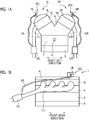
- FIG. 1A is a schematic drawing in which an engine 1 is seen from a direction along the shaft center of a crankshaft 8.
- FIG. 1B is a schematic drawing in which the engine 1 is seen from a direction orthogonal to the shaft center of the crankshaft 8.
- the right-left direction of the engine 1 is illustrated in FIG. 1A .
- the front-rear direction of the engine 1 is illustrated in FIG. 1B .
- the front-rear direction of the engine 1 is a direction perpendicular to the page of FIG. 1A .
- the right-left direction of the engine 1 is a direction perpendicular to the page of FIG. 1B .
- the front-rear direction of the engine 1 is a direction parallel to the shaft center of the crankshaft 8.
- the right-left direction of the engine 1 is a direction perpendicular to the shaft center of the crankshaft 8.
- the engine 1 is mounted in, for example, a vehicle.
- the engine 1 is a V-type engine that has a pair of banks 2R, 2L protruding in a V-shape on a cylinder block 6.
- the banks 2R, 2L are provided with cylinder heads 5R, 5L installed on the upper end portion of the cylinder block 6 and head covers 4R, 4L respectively attached to the upper ends of the cylinder heads 5R, 5L, respectively.
- Four cylinders are disposed for each of the banks 2R, 2L in the cylinder block 6.
- a piston is disposed in each of the cylinders.
- Each of the pistons is connected to the crankshaft 8 so as to transmit power to the crankshaft 8.
- a crankcase 7 is attached to the lower side of the cylinder block 6.
- An oil pan 9 as an oil reservoir is arranged beneath the crankcase 7.
- Exhaust passages 11R, 11L are connected to the cylinder heads 5R, 5L, respectively.
- Particulate filters 12R, 12L are disposed on the exhaust passages 11R, 11L, respectively.
- Intake passages (not illustrated) are connected to the cylinder heads 5R, 5L, respectively.
- the head covers 4R, 4L are provided with sensors 14R, 14L, respectively.
- the sensors 14R, 14L are attached on the head covers 4R, 4L by attachment mechanisms 20R, 20L, respectively.
- the sensor 14L is connected to the upstream side of the particulate filter 12L via a pipe 16L.
- the sensor 14R is connected to the upstream side of the particulate filter 12R via a pipe 16R.
- the sensors 14R, 14L are sensors detecting the pressures of the upstream sides of the particulate filters 12R, 12L, respectively.
- the invention is not limited thereto, and the sensors 14R, 14L may detect the pressures of the downstream sides of the particulate filters 12R, 12L instead.
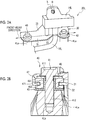
- FIG. 2A is an explanatory diagram of the attachment mechanism 20L.
- the attachment mechanism 20L has a bracket 30 and support portions 40.
- the bracket 30 has a bottom wall portion 31 and a side wall portion 35 extending vertically upward from the bottom wall portion 31.
- the bottom wall portion 31 has a flat plate shape, and the front-rear direction of the engine 1 is the longitudinal direction of the bottom wall portion 31.
- two projecting portions 4La protrude vertically upward.
- the bottom wall portion 31 is attached to the projecting portions 4La by the two support portions 40.
- the two support portions 40 and the two projecting portions 4La are apart from each other respectively in the front-rear direction of the engine 1.
- a notch portion 33 is formed between the two support portions 40, which will be described in detail later.
- the sensor 14L is fixed to the side wall portion 35 by a bolt B and a nut N.
- FIG. 2B is a sectional view of the support portion 40.
- the support portion 40 includes a bolt 41, a washer 43, a spacer 45, and a grommet 47.
- the bolt 41 has a head portion 411 and a shaft portion 412 that is smaller in diameter than the head portion 411, is long in the axial direction thereof, and has a screw groove formed in the outer periphery thereof.
- the head portion 411 is screwed into a screw hole 4Lb formed in the projecting portion 4La through a hole 32 formed in the bottom wall portion 31.
- the spacer 45 is made of metal and has a tubular portion 451 and a disk-shaped disk portion 452 radially expanding from the tubular portion 451.
- the shaft portion 412 of the bolt 41 penetrates the tubular portion 451 of the spacer 45.
- the disk portion 452 is in contact with the upper end surface of the projecting portion 4La.
- the washer 43 is made of metal and is positioned between the grommet 47 and the head portion 411 of the bolt 41. In other words, the grommet 47 is sandwiched between the washer 43 and the disk portion 452 of the spacer 45.
- the grommet 47 is made of rubber and has a substantially annular shape. In the circumferential direction of the grommet 47, a recessed portion 471 is formed in the circumferential direction.
- the grommet 47 is fitted to the outside of the tubular portion 451 of the spacer 45, the recessed portion 471 of the grommet 47 is fitted with the hole 32 of the bottom wall portion 31, and the grommet 47 is sandwiched between the washer 43 and the disk portion 452 of the spacer 45 as described above.
- the bottom wall portion 31 of the bracket 30 is fixed to the screw hole 4Lb of the projecting portion 4La via the grommet 47.
- the support portion 40 elastically supports the bracket 30 with respect to the head cover 4L of the engine. Accordingly, vibration of the engine 1 is damped by the grommet 47 and transmission of significant vibration to the bracket 30 and the sensor 14L held by the bracket 30 is suppressed.
- FIG. 3 is a graph illustrating an excitation frequency-vibration magnification relationship in a case where vibration has been applied to an object supported by a spring.
- the horizontal axis represents an excitation frequency
- the vertical axis represents a vibration magnification.
- the dotted line represents a case where a spring constant K is large
- the solid line represents a case where the spring constant K is small. It is known that a resonance peak frequency decreases as the spring constant K decreases. Accordingly, the region of the excitation frequency with a vibration magnification of 1 or less increases as the spring constant K decreases. In other words, it is shown that vibration is effectively damped when the spring constant K is small.
- the two support portions 40 are disposed along the front-rear direction of the engine 1 as described above. Accordingly, it can be regarded that the bracket 30 is supported by merely one of the support portions 40 with respect to vibration of the engine 1 in the right-left direction whereas the bracket 30 is supported by the two support portions 40 with respect to vibration of the engine 1 in the front-rear direction. Therefore, it can be regarded that the spring constant of a spring supporting the bracket 30 with respect to vibration of the engine 1 in the right-left direction is smaller than the spring constant of a spring supporting the bracket 30 with respect to vibration of the engine 1 in the front-rear direction. As a result, vibration of the bracket 30 in the right-left direction of the engine 1 can be effectively damped with respect to the front-rear direction of the engine 1.
- the banks 2R, 2L resonate in the arc direction about the crankshaft 8 in some cases due to reciprocation of the pistons respectively disposed in the banks 2R, 2L.
- vibration of the engine 1 in the right-left direction exceeds vibration of the engine 1 in the front-rear direction.
- vibration of the bracket 30 in the right-left direction of the engine 1 can be effectively damped by means of a simple configuration in which the two support portions 40 are disposed along the front-rear direction of the engine 1 as described above.
- adverse effects on the sensor 14L held by the bracket 30 also can be further suppressed.
- the attachment mechanism 20L has a simple configuration as described above, the attachment mechanism 20L can be adopted even in a case where the space surrounding the engine 1 is narrow. Although the engine 1 vibrates also in the up-down direction due to the reciprocation of the pistons in the banks 2R, 2L, the vibration in the up-down direction also can be damped by the grommets 47 of the two support portions 40.
- the pipe 16L is connected to the sensor 14L and the pipe 16L communicates with the exhaust passage 11L. Exhaust gas flowing through the exhaust passage 11L may cause condensed water to be generated in the pipe 16L.
- the sensor 14L is attached to the head cover 4L by the attachment mechanism 20L, and thus is positioned vertically above the part where the pipe 16L and the exhaust passage 11L are interconnected.
- the side wall portion 35 of the bracket 30 is positioned vertically above the bottom wall portion 31 and holds the sensor 14L, and thus the sensor 14L is held by the bracket 30 on a vertically higher side.
- the part of the pipe 16L that is connected to the sensor 14L is positioned on a vertically higher side, and discharge of the condensed water generated in the pipe 16L into the exhaust passage 11L is promoted by gravity. As a result, the impact of condensed water accumulation in the pipe 16L on the detection accuracy of the sensor 14L can be further suppressed.
- the end portion of the pipe 16L on the sensor 14L side passes through the notch portion 33 formed in the bottom wall portion 31 as illustrated in FIG. 2A , and interference with the bottom wall portion 31 is suppressed. As a result, the end portion of the pipe 16L on the sensor 14L side can be routed vertically downward, and the degree of freedom of routing of the pipe 16L is improved.
- the two support portions 40 are arranged along the front-rear direction of the engine 1 as described above, this does not mean that the line segment interconnecting the two support portions 40 is needed to be parallel to the front-rear direction of the engine 1.
- the line segment may be inclined to some extent with respect to the front-rear direction.
- the distance between the two adjacent support portions 40 in the front-rear direction of the engine 1 may be longer than the distance between the two adjacent support portions 40 in the right-left direction of the engine 1.
- the two support portions 40 are disposed along the front-rear direction of the engine 1 in the above-described example, three or more support portions 40 may be disposed along the front-rear direction of the engine 1 instead.
- a coil spring, an annular leaf spring, or the like may be adopted instead of the grommet 47.
- V-type engine has been exemplified in this example
- the invention is also applicable to an in-line engine. Also in a case where the invention is applied to an in-line engine, vibration of the engine in the right-left direction exceeds vibration of the engine in the front-rear direction as a result of rotation of the crankshaft 8.
- a sensor detecting the internal pressure of an exhaust system has been described as an example of electronic equipment.
- the electronic equipment may also be a pressure sensor connected to a pipe communicating with either the intake system or the exhaust system of an engine.
- the electronic equipment may also be an electromagnetic valve such as a vacuum switching valve for purging or a driver device driving a direct injection injector of an engine. This is because any of the electronic equipment can be installed near the head cover of the engine and may be affected by transmission of significant vibration.
Landscapes
- Engineering & Computer Science (AREA)
- General Engineering & Computer Science (AREA)
- Mechanical Engineering (AREA)
- Chemical & Material Sciences (AREA)
- Combustion & Propulsion (AREA)
- Cylinder Crankcases Of Internal Combustion Engines (AREA)
- Exhaust Silencers (AREA)
Abstract
An attachment mechanism (20R, 20L) for electronic equipment for an engine (1) includes a bracket (30) configured to hold the electronic equipment and a plurality of support portions (40) configured to elastically support the bracket (30) with respect to a head cover (4L) of the engine (1). The support portions (40) are disposed such that a maximum distance between two support portions of the support portions (40) in a direction parallel to a shaft center of a crankshaft (8) of the engine (1) is longer than a maximum distance between the two support portions of the support portions (40) in a direction perpendicular to the shaft center of the crankshaft (8) of the engine (1).
Description
- The invention relates to an attachment mechanism for electronic equipment for an engine.
- In some cases, electronic equipment such as a cam angle sensor is attached to a head cover covering a cylinder head of an engine (refer to, for example, Japanese Unexamined Patent Application Publication No.
2010-261361 JP 2010-261361 A - The electronic equipment may be adversely affected once vibration from the engine is transmitted to the electronic equipment. Desirable in this regard is damping of the vibration during the transmission of the vibration from the engine to the electronic equipment. In a case where the engine is mounted in a vehicle or the like, damping of the vibration as described above by means of a simple configuration is desired for surrounding spatial constraints. Based on the structure of the engine, a direction in which the vibration is likely to become significant is determined in advance.
- The invention provides an attachment mechanism for electronic equipment for an engine with which vibration from an engine can be effectively damped by means of a simple configuration.
- An aspect of the invention relates to an attachment mechanism for electronic equipment for an engine. The attachment mechanism includes a bracket configured to hold the electronic equipment and a plurality of support portions configured to elastically support the bracket with respect to a head cover covering a cylinder head of the engine (hereinafter, referred to as a "head cover"). The support portions are disposed such that a maximum distance between two support portions of the support portions in a direction parallel to a shaft center of a crankshaft of the engine is longer than a maximum distance between the two support portions of the support portions in a direction perpendicular to the shaft center of the crankshaft of the engine.
- In the attachment mechanism according to the aspect of the invention, the electronic equipment may include any one of a sensor, an electromagnetic valve, and a driver device driving a direct injection injector of the engine.
- In the attachment mechanism according to the aspect of the invention, the electronic equipment may be a pressure sensor connected to a pipe that communicates with either an intake system or an exhaust system of the engine. The bracket may be configured to hold the pressure sensor at a position vertically above a part where the pipe and the intake system or the exhaust system communicate with each other. The bracket may include a bottom wall portion attached to the head cover by the support portions and a side wall portion that extends vertically upward from the bottom wall portion and holds the pressure sensor.
- In the attachment mechanism according to the aspect of the invention, the bottom wall portion may include a notch portion configured to allow the pipe to pass through the notch portion between the support portions.
- In the attachment mechanism according to the aspect of the invention, the support portion may include an elastic body interposed between the head cover and the bottom wall portion.
- According to the aspect of the invention, an attachment mechanism for electronic equipment for an engine with which vibration from an engine can be effectively damped by means of a simple configuration can be provided.
- Features, advantages, and technical and industrial significance of exemplary embodiments of the invention will be described below with reference to the accompanying drawings, in which like numerals denote like elements, and wherein:
-
FIG. 1A is a schematic drawing in which an engine is seen from a direction along the shaft center of a crankshaft; -
FIG. 1B is a schematic drawing in which the engine is seen from a direction orthogonal to the shaft center of the crankshaft; -
FIG. 2A is an explanatory diagram of an attachment mechanism; -
FIG. 2B is a sectional view of a support portion; and -
FIG. 3 is a graph illustrating an excitation frequency-vibration magnification relationship in a case where vibration has been applied to an object supported by a spring. -
FIG. 1A is a schematic drawing in which anengine 1 is seen from a direction along the shaft center of acrankshaft 8.FIG. 1B is a schematic drawing in which theengine 1 is seen from a direction orthogonal to the shaft center of thecrankshaft 8. The right-left direction of theengine 1 is illustrated inFIG. 1A . The front-rear direction of theengine 1 is illustrated inFIG. 1B . The front-rear direction of theengine 1 is a direction perpendicular to the page ofFIG. 1A . The right-left direction of theengine 1 is a direction perpendicular to the page ofFIG. 1B . The front-rear direction of theengine 1 is a direction parallel to the shaft center of thecrankshaft 8. The right-left direction of theengine 1 is a direction perpendicular to the shaft center of thecrankshaft 8. Theengine 1 is mounted in, for example, a vehicle. - The
engine 1 is a V-type engine that has a pair ofbanks banks cylinder heads cylinder heads banks crankshaft 8 so as to transmit power to thecrankshaft 8. Furthermore, acrankcase 7 is attached to the lower side of the cylinder block 6. Anoil pan 9 as an oil reservoir is arranged beneath thecrankcase 7.Exhaust passages cylinder heads Particulate filters exhaust passages cylinder heads - The head covers 4R, 4L are provided with
sensors sensors attachment mechanisms sensor 14L is connected to the upstream side of theparticulate filter 12L via apipe 16L. Likewise, thesensor 14R is connected to the upstream side of theparticulate filter 12R via apipe 16R. Thesensors particulate filters sensors particulate filters - The
attachment mechanism 20L will be described in detail below. Theattachment mechanism 20R has almost the same configuration as theattachment mechanism 20L, and thus description of theattachment mechanism 20R will be omitted.FIG. 2A is an explanatory diagram of theattachment mechanism 20L. Theattachment mechanism 20L has abracket 30 andsupport portions 40. Thebracket 30 has abottom wall portion 31 and aside wall portion 35 extending vertically upward from thebottom wall portion 31. Thebottom wall portion 31 has a flat plate shape, and the front-rear direction of theengine 1 is the longitudinal direction of thebottom wall portion 31. In thehead cover 4L, two projecting portions 4La protrude vertically upward. Thebottom wall portion 31 is attached to the projecting portions 4La by the twosupport portions 40. The twosupport portions 40 and the two projecting portions 4La are apart from each other respectively in the front-rear direction of theengine 1. In thebottom wall portion 31, anotch portion 33 is formed between the twosupport portions 40, which will be described in detail later. Thesensor 14L is fixed to theside wall portion 35 by a bolt B and a nut N. -
FIG. 2B is a sectional view of thesupport portion 40. Thesupport portion 40 includes abolt 41, awasher 43, aspacer 45, and agrommet 47. Thebolt 41 has ahead portion 411 and ashaft portion 412 that is smaller in diameter than thehead portion 411, is long in the axial direction thereof, and has a screw groove formed in the outer periphery thereof. Thehead portion 411 is screwed into a screw hole 4Lb formed in the projecting portion 4La through ahole 32 formed in thebottom wall portion 31. Thespacer 45 is made of metal and has atubular portion 451 and a disk-shapeddisk portion 452 radially expanding from thetubular portion 451. Theshaft portion 412 of thebolt 41 penetrates thetubular portion 451 of thespacer 45. Thedisk portion 452 is in contact with the upper end surface of the projecting portion 4La. Thewasher 43 is made of metal and is positioned between thegrommet 47 and thehead portion 411 of thebolt 41. In other words, thegrommet 47 is sandwiched between thewasher 43 and thedisk portion 452 of thespacer 45. Thegrommet 47 is made of rubber and has a substantially annular shape. In the circumferential direction of thegrommet 47, a recessedportion 471 is formed in the circumferential direction. Thegrommet 47 is fitted to the outside of thetubular portion 451 of thespacer 45, the recessedportion 471 of thegrommet 47 is fitted with thehole 32 of thebottom wall portion 31, and thegrommet 47 is sandwiched between thewasher 43 and thedisk portion 452 of thespacer 45 as described above. - In the above-described manner, the
bottom wall portion 31 of thebracket 30 is fixed to the screw hole 4Lb of the projecting portion 4La via thegrommet 47. In other words, thesupport portion 40 elastically supports thebracket 30 with respect to thehead cover 4L of the engine. Accordingly, vibration of theengine 1 is damped by thegrommet 47 and transmission of significant vibration to thebracket 30 and thesensor 14L held by thebracket 30 is suppressed. - The two
support portions 40 are disposed along the front-rear direction of theengine 1 as illustrated inFIG. 2A , and thus vibration of thebracket 30 in the right-left direction of theengine 1 can be effectively damped with respect to vibration of thebracket 30 in the front-rear direction of theengine 1. The reason will be described below.FIG. 3 is a graph illustrating an excitation frequency-vibration magnification relationship in a case where vibration has been applied to an object supported by a spring. The horizontal axis represents an excitation frequency, and the vertical axis represents a vibration magnification. The dotted line represents a case where a spring constant K is large, and the solid line represents a case where the spring constant K is small. It is known that a resonance peak frequency decreases as the spring constant K decreases. Accordingly, the region of the excitation frequency with a vibration magnification of 1 or less increases as the spring constant K decreases. In other words, it is shown that vibration is effectively damped when the spring constant K is small. - In this example, the two
support portions 40 are disposed along the front-rear direction of theengine 1 as described above. Accordingly, it can be regarded that thebracket 30 is supported by merely one of thesupport portions 40 with respect to vibration of theengine 1 in the right-left direction whereas thebracket 30 is supported by the twosupport portions 40 with respect to vibration of theengine 1 in the front-rear direction. Therefore, it can be regarded that the spring constant of a spring supporting thebracket 30 with respect to vibration of theengine 1 in the right-left direction is smaller than the spring constant of a spring supporting thebracket 30 with respect to vibration of theengine 1 in the front-rear direction. As a result, vibration of thebracket 30 in the right-left direction of theengine 1 can be effectively damped with respect to the front-rear direction of theengine 1. - In the V-
type engine 1, thebanks crankshaft 8 in some cases due to reciprocation of the pistons respectively disposed in thebanks engine 1 in the right-left direction exceeds vibration of theengine 1 in the front-rear direction. Accordingly, vibration of thebracket 30 in the right-left direction of theengine 1 can be effectively damped by means of a simple configuration in which the twosupport portions 40 are disposed along the front-rear direction of theengine 1 as described above. As a result, adverse effects on thesensor 14L held by thebracket 30 also can be further suppressed. Since theattachment mechanism 20L has a simple configuration as described above, theattachment mechanism 20L can be adopted even in a case where the space surrounding theengine 1 is narrow. Although theengine 1 vibrates also in the up-down direction due to the reciprocation of the pistons in thebanks grommets 47 of the twosupport portions 40. - As illustrated in
FIGS. 1A and 1B , thepipe 16L is connected to thesensor 14L and thepipe 16L communicates with theexhaust passage 11L. Exhaust gas flowing through theexhaust passage 11L may cause condensed water to be generated in thepipe 16L. Here, thesensor 14L is attached to thehead cover 4L by theattachment mechanism 20L, and thus is positioned vertically above the part where thepipe 16L and theexhaust passage 11L are interconnected. Theside wall portion 35 of thebracket 30 is positioned vertically above thebottom wall portion 31 and holds thesensor 14L, and thus thesensor 14L is held by thebracket 30 on a vertically higher side. As a result, the part of thepipe 16L that is connected to thesensor 14L is positioned on a vertically higher side, and discharge of the condensed water generated in thepipe 16L into theexhaust passage 11L is promoted by gravity. As a result, the impact of condensed water accumulation in thepipe 16L on the detection accuracy of thesensor 14L can be further suppressed. - The end portion of the
pipe 16L on thesensor 14L side passes through thenotch portion 33 formed in thebottom wall portion 31 as illustrated inFIG. 2A , and interference with thebottom wall portion 31 is suppressed. As a result, the end portion of thepipe 16L on thesensor 14L side can be routed vertically downward, and the degree of freedom of routing of thepipe 16L is improved. - Although an example of the invention has been described in detail above, the invention is not limited to the above-described specific example and can be modified and changed in various forms within the scope of the invention set forth in the claims.
- Although the two
support portions 40 are arranged along the front-rear direction of theengine 1 as described above, this does not mean that the line segment interconnecting the twosupport portions 40 is needed to be parallel to the front-rear direction of theengine 1. Alternatively, the line segment may be inclined to some extent with respect to the front-rear direction. In other words, the distance between the twoadjacent support portions 40 in the front-rear direction of theengine 1 may be longer than the distance between the twoadjacent support portions 40 in the right-left direction of theengine 1. Although the twosupport portions 40 are disposed along the front-rear direction of theengine 1 in the above-described example, three ormore support portions 40 may be disposed along the front-rear direction of theengine 1 instead. A coil spring, an annular leaf spring, or the like may be adopted instead of thegrommet 47. - Although a V-type engine has been exemplified in this example, the invention is also applicable to an in-line engine. Also in a case where the invention is applied to an in-line engine, vibration of the engine in the right-left direction exceeds vibration of the engine in the front-rear direction as a result of rotation of the
crankshaft 8. - In the above-described example, a sensor detecting the internal pressure of an exhaust system has been described as an example of electronic equipment. However, the invention is not limited thereto. For example, the electronic equipment may also be a pressure sensor connected to a pipe communicating with either the intake system or the exhaust system of an engine. The electronic equipment may also be an electromagnetic valve such as a vacuum switching valve for purging or a driver device driving a direct injection injector of an engine. This is because any of the electronic equipment can be installed near the head cover of the engine and may be affected by transmission of significant vibration.
Claims (5)
- An attachment mechanism (20R, 20L) for electronic equipment for an engine (1), the attachment mechanism (20R, 20L) comprising:a bracket (30) configured to hold the electronic equipment; anda plurality of support portions (40) configured to elastically support the bracket (30) with respect to a head cover (4R, 4L) of the engine (1), the support portions (40) being disposed such that a maximum distance between two support portions of the support portions (40) in a direction parallel to a shaft center of a crankshaft (8) of the engine (1) is longer than a maximum distance between the two support portions of the support portions (40) in a direction perpendicular to the shaft center of the crankshaft (8) of the engine (1).
- The attachment mechanism (20R, 20L) according to claim 1, wherein the electronic equipment includes any one of a sensor (14R, 14L), an electromagnetic valve, and a driver device driving a direct injection injector of the engine (1).
- The attachment mechanism (20R, 20L) according to claim 2, wherein:the electronic equipment is a pressure sensor connected to a pipe that communicates with either an intake system or an exhaust system of the engine (1);the bracket (30) is configured to hold the pressure sensor at a position vertically above a part where the pipe and the intake system or the exhaust system communicate with each other; andthe bracket (30) includes a bottom wall portion (31) attached to the head cover (4R, 4L) by the support portions (40) and a side wall portion (35) that extends vertically upward from the bottom wall portion (31) and holds the pressure sensor.
- The attachment mechanism (20R, 20L) according to claim 3, wherein the bottom wall portion (31) includes a notch portion (33) configured to allow the pipe (16R, 16L) to pass through the notch portion (33) between the support portions (40).
- The attachment mechanism (20R, 20L) according to claim 3 or 4, wherein the support portion (40) includes an elastic body interposed between the head cover (4R, 4L) and the bottom wall portion (31).
Applications Claiming Priority (1)
| Application Number | Priority Date | Filing Date | Title |
|---|---|---|---|
| JP2017220304A JP6863243B2 (en) | 2017-11-15 | 2017-11-15 | Electronic device mounting mechanism |
Publications (1)
| Publication Number | Publication Date |
|---|---|
| EP3486472A1 true EP3486472A1 (en) | 2019-05-22 |
Family
ID=63798815
Family Applications (1)
| Application Number | Title | Priority Date | Filing Date |
|---|---|---|---|
| EP18197606.9A Pending EP3486472A1 (en) | 2017-11-15 | 2018-09-28 | Attachment mechanism for electronic equipment for engine |
Country Status (4)
| Country | Link |
|---|---|
| US (1) | US11168831B2 (en) |
| EP (1) | EP3486472A1 (en) |
| JP (1) | JP6863243B2 (en) |
| CN (1) | CN109779778B (en) |
Families Citing this family (1)
| Publication number | Priority date | Publication date | Assignee | Title |
|---|---|---|---|---|
| JP7016596B2 (en) * | 2020-03-17 | 2022-02-07 | ダイハツ工業株式会社 | Support bracket |
Citations (8)
| Publication number | Priority date | Publication date | Assignee | Title |
|---|---|---|---|---|
| JPH10223111A (en) * | 1997-02-03 | 1998-08-21 | Honda Motor Co Ltd | Outboard relay |
| US5813886A (en) * | 1996-01-31 | 1998-09-29 | Suzuki Kabushiki Kaisha | Structure for mounting control sensor in outboard motor engine |
| US6170516B1 (en) * | 1998-11-27 | 2001-01-09 | Mitsubishi Denki Kabushiki Kaisha | Solenoid valve fixing structure |
| US20040007212A1 (en) * | 2002-04-19 | 2004-01-15 | Masahiko Kato | Engine with fuel injection system |
| EP1852884A1 (en) * | 2006-05-01 | 2007-11-07 | Honda Motor Co., Ltd | Outboard engine unit |
| JP2010261361A (en) | 2009-05-07 | 2010-11-18 | Toyota Motor Corp | Cylinder head cover |
| EP2693023A1 (en) * | 2011-03-31 | 2014-02-05 | Mitsubishi Heavy Industries, Ltd. | Installation device for instrumentation device of stationary engine |
| CN203978605U (en) * | 2014-08-01 | 2014-12-03 | 东风汽车公司 | The linkage structure of a kind of motor and pressurized machine |
Family Cites Families (14)
| Publication number | Priority date | Publication date | Assignee | Title |
|---|---|---|---|---|
| JP2001342918A (en) * | 2000-05-31 | 2001-12-14 | Suzuki Motor Corp | Outboard intake manifold |
| JP4061968B2 (en) * | 2002-05-23 | 2008-03-19 | ヤマハマリン株式会社 | Fuel injection engine and outboard motor |
| JP2006220073A (en) | 2005-02-10 | 2006-08-24 | Toyota Motor Corp | Sensor mounting structure and cam cap structure for internal combustion engine |
| JP5171427B2 (en) * | 2008-06-23 | 2013-03-27 | ダイハツ工業株式会社 | Cam angle sensor mounting apparatus for internal combustion engine |
| JP5496840B2 (en) | 2010-09-14 | 2014-05-21 | 愛三工業株式会社 | Sensor mounting structure |
| JP2013124714A (en) * | 2011-12-14 | 2013-06-24 | Ud Trucks Corp | Fixing member of control device |
| JP6015599B2 (en) * | 2013-08-30 | 2016-10-26 | アイシン精機株式会社 | Sensor support structure |
| DE102013219399B4 (en) * | 2013-09-26 | 2023-01-05 | Robert Bosch Gmbh | Arrangement for plugging a sensor into a passage opening of a flow channel so that it cannot rotate |
| JP6201858B2 (en) * | 2014-03-27 | 2017-09-27 | マツダ株式会社 | Engine cylinder head structure |
| JP6255611B2 (en) * | 2015-05-29 | 2018-01-10 | 本田技研工業株式会社 | Piping connection structure |
| JP6366141B2 (en) * | 2015-05-29 | 2018-08-01 | 本田技研工業株式会社 | Saddle riding |
| CN205931277U (en) * | 2016-08-15 | 2017-02-08 | 中国航空工业集团公司沈阳发动机设计研究所 | Take bracket component of double -deck damping pad |
| CN206111308U (en) | 2016-08-31 | 2017-04-19 | 长沙金鹰机电科技有限公司 | New type anti -explosion diesel engine |
| CN206111343U (en) | 2016-08-31 | 2017-04-19 | 长沙金鹰机电科技有限公司 | Diesel engine blast resistant construction |
-
2017
- 2017-11-15 JP JP2017220304A patent/JP6863243B2/en active Active
-
2018
- 2018-09-25 US US15/929,049 patent/US11168831B2/en active Active
- 2018-09-28 EP EP18197606.9A patent/EP3486472A1/en active Pending
- 2018-10-31 CN CN201811284053.5A patent/CN109779778B/en not_active Expired - Fee Related
Patent Citations (8)
| Publication number | Priority date | Publication date | Assignee | Title |
|---|---|---|---|---|
| US5813886A (en) * | 1996-01-31 | 1998-09-29 | Suzuki Kabushiki Kaisha | Structure for mounting control sensor in outboard motor engine |
| JPH10223111A (en) * | 1997-02-03 | 1998-08-21 | Honda Motor Co Ltd | Outboard relay |
| US6170516B1 (en) * | 1998-11-27 | 2001-01-09 | Mitsubishi Denki Kabushiki Kaisha | Solenoid valve fixing structure |
| US20040007212A1 (en) * | 2002-04-19 | 2004-01-15 | Masahiko Kato | Engine with fuel injection system |
| EP1852884A1 (en) * | 2006-05-01 | 2007-11-07 | Honda Motor Co., Ltd | Outboard engine unit |
| JP2010261361A (en) | 2009-05-07 | 2010-11-18 | Toyota Motor Corp | Cylinder head cover |
| EP2693023A1 (en) * | 2011-03-31 | 2014-02-05 | Mitsubishi Heavy Industries, Ltd. | Installation device for instrumentation device of stationary engine |
| CN203978605U (en) * | 2014-08-01 | 2014-12-03 | 东风汽车公司 | The linkage structure of a kind of motor and pressurized machine |
Also Published As
| Publication number | Publication date |
|---|---|
| CN109779778A (en) | 2019-05-21 |
| JP6863243B2 (en) | 2021-04-21 |
| US20190145575A1 (en) | 2019-05-16 |
| JP2019090379A (en) | 2019-06-13 |
| US11168831B2 (en) | 2021-11-09 |
| CN109779778B (en) | 2021-11-02 |
Similar Documents
| Publication | Publication Date | Title |
|---|---|---|
| JP5803680B2 (en) | Bi-fuel engine for vehicles | |
| US8763996B2 (en) | Active vibration isolating support apparatus and method for controlling the same | |
| KR101492872B1 (en) | Anti-vibration device | |
| US7717409B2 (en) | Active vibration isolating support apparatus | |
| US10421347B2 (en) | Head cover structure of engine and suspension structure thereof | |
| JP5261589B1 (en) | Bulldozer | |
| EP3486472A1 (en) | Attachment mechanism for electronic equipment for engine | |
| JP2019120166A (en) | Internal combustion engine | |
| JP7264801B2 (en) | spark ignition engine | |
| EP0851109A1 (en) | Water-cooled type internal combustion engine | |
| CN111485997B (en) | Integrated mounting structure for engine | |
| KR20030031722A (en) | Engine mounting apparatus | |
| JP5548570B2 (en) | Vibration reduction device | |
| JP5491994B2 (en) | Vibration isolator | |
| RU2169279C1 (en) | Piston engine | |
| KR20050096585A (en) | Throttle body fixing structure | |
| JPH0658356A (en) | Bracket for vibration control device | |
| JP2025077085A (en) | Internal combustion engine | |
| JP2013124714A (en) | Fixing member of control device | |
| JP2008045748A (en) | Hydraulic vibration isolating mount | |
| CN112105806B (en) | Internal combustion engines for motor vehicles, especially motor vehicles, and motor vehicles | |
| WO2025099786A1 (en) | Internal combustion engine | |
| JP6552153B2 (en) | Vibration control device | |
| JP2006348827A (en) | Internal combustion engine with variable compression ratio mechanism | |
| KR100846039B1 (en) | Stopper integrated engine mount |
Legal Events
| Date | Code | Title | Description |
|---|---|---|---|
| PUAI | Public reference made under article 153(3) epc to a published international application that has entered the european phase |
Free format text: ORIGINAL CODE: 0009012 |
|
| STAA | Information on the status of an ep patent application or granted ep patent |
Free format text: STATUS: REQUEST FOR EXAMINATION WAS MADE |
|
| 17P | Request for examination filed |
Effective date: 20181027 |
|
| AK | Designated contracting states |
Kind code of ref document: A1 Designated state(s): AL AT BE BG CH CY CZ DE DK EE ES FI FR GB GR HR HU IE IS IT LI LT LU LV MC MK MT NL NO PL PT RO RS SE SI SK SM TR |
|
| AX | Request for extension of the european patent |
Extension state: BA ME |
|
| STAA | Information on the status of an ep patent application or granted ep patent |
Free format text: STATUS: EXAMINATION IS IN PROGRESS |
|
| 17Q | First examination report despatched |
Effective date: 20211104 |