EP3486426B1 - Unterwassersystem mit landeanzeige - Google Patents
Unterwassersystem mit landeanzeige Download PDFInfo
- Publication number
- EP3486426B1 EP3486426B1 EP18206274.5A EP18206274A EP3486426B1 EP 3486426 B1 EP3486426 B1 EP 3486426B1 EP 18206274 A EP18206274 A EP 18206274A EP 3486426 B1 EP3486426 B1 EP 3486426B1
- Authority
- EP
- European Patent Office
- Prior art keywords
- poppet valve
- tubing hanger
- tubing
- poppet
- landing
- Prior art date
- Legal status (The legal status is an assumption and is not a legal conclusion. Google has not performed a legal analysis and makes no representation as to the accuracy of the status listed.)
- Active
Links
Images

Classifications
-
- E—FIXED CONSTRUCTIONS
- E21—EARTH OR ROCK DRILLING; MINING
- E21B—EARTH OR ROCK DRILLING; OBTAINING OIL, GAS, WATER, SOLUBLE OR MELTABLE MATERIALS OR A SLURRY OF MINERALS FROM WELLS
- E21B19/00—Handling rods, casings, tubes or the like outside the borehole, e.g. in the derrick; Apparatus for feeding the rods or cables
- E21B19/16—Connecting or disconnecting pipe couplings or joints
- E21B19/165—Control or monitoring arrangements therefor
-
- E—FIXED CONSTRUCTIONS
- E21—EARTH OR ROCK DRILLING; MINING
- E21B—EARTH OR ROCK DRILLING; OBTAINING OIL, GAS, WATER, SOLUBLE OR MELTABLE MATERIALS OR A SLURRY OF MINERALS FROM WELLS
- E21B33/00—Sealing or packing boreholes or wells
- E21B33/02—Surface sealing or packing
- E21B33/03—Well heads; Setting-up thereof
- E21B33/04—Casing heads; Suspending casings or tubings in well heads
- E21B33/043—Casing heads; Suspending casings or tubings in well heads specially adapted for underwater well heads
-
- E—FIXED CONSTRUCTIONS
- E21—EARTH OR ROCK DRILLING; MINING
- E21B—EARTH OR ROCK DRILLING; OBTAINING OIL, GAS, WATER, SOLUBLE OR MELTABLE MATERIALS OR A SLURRY OF MINERALS FROM WELLS
- E21B34/00—Valve arrangements for boreholes or wells
- E21B34/02—Valve arrangements for boreholes or wells in well heads
- E21B34/04—Valve arrangements for boreholes or wells in well heads in underwater well heads
-
- E—FIXED CONSTRUCTIONS
- E21—EARTH OR ROCK DRILLING; MINING
- E21B—EARTH OR ROCK DRILLING; OBTAINING OIL, GAS, WATER, SOLUBLE OR MELTABLE MATERIALS OR A SLURRY OF MINERALS FROM WELLS
- E21B47/00—Survey of boreholes or wells
- E21B47/001—Survey of boreholes or wells for underwater installation
-
- E—FIXED CONSTRUCTIONS
- E21—EARTH OR ROCK DRILLING; MINING
- E21B—EARTH OR ROCK DRILLING; OBTAINING OIL, GAS, WATER, SOLUBLE OR MELTABLE MATERIALS OR A SLURRY OF MINERALS FROM WELLS
- E21B47/00—Survey of boreholes or wells
- E21B47/10—Locating fluid leaks, intrusions or movements
- E21B47/117—Detecting leaks, e.g. from tubing, by pressure testing
Definitions
- Hydrocarbon fluids such as oil and natural gas are obtained from a subterranean geologic formation, referred to as a reservoir, by drilling a well that penetrates the hydrocarbon-bearing geologic formation.
- the well is drilled at a subsea location and various types of equipment are used to complete the well and enable production of the hydrocarbon fluids.
- a subsea wellhead assembly is positioned over the well and may include several types of components and systems.
- the subsea wellhead assembly may comprise a tubing head spool structured to receive a tubing hanger. Sometimes difficulties may arise in determining whether the tubing hanger has been properly landed in the tubing head spool.
- a system and methodology are provided for facilitating landing of a subsea component, e.g. a tubing hanger, by utilizing a poppet valve to provide an indication of proper landing.
- the poppet valve is combined with the tubing hanger or other subsea component and oriented to engage a corresponding landing surface.
- a pressure line is routed to the poppet valve, and the poppet valve is biased to an open flow position with respect to the pressure line during deployment. If the subsea component is properly landed, the corresponding landing surface is able to shift the poppet valve to a closed position. The closed position may be verified via pressure testing through the pressure line.
- WO2017/150982 describes a subsea well equipment landing body comprising an indicator assembly to indicate landing of the landing body or to indicate locking of the landing body.
- the indicator assembly has a stem bore and a sliding stem within the stem bore that has a stem head protruding beyond an external face of the landing body.
- a stem channel in the sliding stem extends between the stem head and a stem channel mouth and is in fluid communication with the outside of the landing body.
- a hydraulic channel in the landing body is in fluid communication with the stem bore.
- the stem channel mouth is positionable in a communicating position, in which there is fluid communication between the hydraulic channel and the stem channel, and a non-communicating position, without fluid communication between the hydraulic channel and the stem channel.
- the present disclosure generally relates to a system and methodology for facilitating landing of a subsea component by utilizing a poppet valve to provide an indication of proper landing.
- the subsea component may be in the form of a tubing hanger which includes the poppet valve in a recess.
- the poppet valve may be combined with the tubing hanger or other subsea component and oriented to engage a landing surface, e.g. a landing surface of a tubing head spool.
- a pressure line is routed to the poppet valve through, for example, the subsea component.
- the pressure line is routed through the tubing hanger to the recess containing the poppet valve in a manner such that the poppet valve may be used to control flow through the pressure line.
- the poppet valve is biased to an open flow position with respect to fluid flow through the pressure line and poppet valve. If the subsea component is properly landed, a landing surface is able to shift the poppet valve to a closed position. The closed position (and thus proper landing) may be verified via pressure testing through the pressure line.
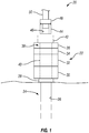
- the subsea well system 20 comprises a subsea installation 22, e.g. a wellhead assembly, positioned over a well 24 comprising a wellbore 26.
- the subsea installation 22 may comprise a variety of components.
- the subsea installation 22 may be in the form of a wellhead assembly having a wellhead hub 28 combined with a casing spool 30 and a tubing head spool 32.
- Other components may include a production tree 34 and a blowout preventer 36.
- a passage 38 referred to as a bore, extends down through the subsea installation 22 to enable interaction with wellbore 26.
- Individual components may include sections of the passage 38, and one example is a tubing head spool bore 40 of tubing head spool 32.
- a riser 42 may be used and may extend up to a surface facility, such as a surface vessel.
- a subsea component e.g. a tubing hanger, 44 having a hanger bore 46 may be being deployed down toward tubing head spool 32.
- the subsea component 44 may comprise components other than a tubing hanger in the other components may similarly be are landed in corresponding components or assemblies.
- the tubing hanger 44 is described herein to facilitate explanation. If riser 42 is employed, the tubing hanger 44 may be deployed down through the riser 42 toward landing in the tubing head spool 32. In this example, the tubing hanger 44 is deployed by a tubing hanger running tool 48 coupled with a conveyance 50, such as a drill string or other tubing.
- the tubing hanger running tool 48 is releasably coupled with the tubing hanger 44 and may be released and retrieved upon verification of proper landing of the tubing hanger 44 in tubing head spool 32 as described in greater detail below. It should again be noted that although landing of the tubing hanger 44 in tubing head spool 32 has been described for purposes of explanation, the landing verification system and methodology described herein may be used with a variety of other types of subsea components landed in corresponding equipment. The other types of subsea components may similarly be delivered through a riser or through open water depending on the parameters of a given operation.
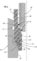
- tubing hanger 44 landed in tubing head spool 32 via tubing hanger running tool 48 is illustrated.
- the tubing hanger 44 is sized for reception in a receptacle 52 of tubing head spool 32.
- Receptacle 52 may be part of or formed along tubing head spool bore 40.
- the tubing hanger 44 has a poppet valve 54 oriented for engagement with a landing surface 56 of tubing head spool 32.
- the poppet valve 54 may be mounted in a recess 58 formed within tubing hanger 44 proximate a tubing hanger landing surface 60.
- the landing surface 56 and corresponding tubing hanger landing surface 60 form a landing surface interface 62 which is properly engaged, e.g. sealably engaged, when tubing hanger 44 is properly landed in tubing head spool 32.
- the tubing hanger 44 also comprises a pressure line 64 routed to the poppet valve 54.
- the pressure line 64 may be placed in fluid communication with recess 58 and thus with poppet valve 54.
- poppet valve 54 When poppet valve 54 is in an open flow position, fluid is able to flow along the pressure line 64 and through poppet valve 54. However, when poppet valve 54 is in a closed flow position, flow along pressure line 64 and through poppet valve 54 is blocked.
- the poppet valve 54 Prior to successfully landing tubing hanger 44 in tubing head spool 32, the poppet valve 54 is biased to an open flow position to allow fluid flow along the pressure line 64 and through the poppet valve 54.
- the pressure line 64 may be placed in communication with a suitable pressure source to enable pressure testing for verification of proper landing.
- the pressure line 64 be placed in fluid communication with a corresponding pressure line 66 routed through tubing hanger running tool 48 via a gallery region 68 located between the tubing hanger 44 and the tubing hanger running tool 48.
- the gallery 68 may be sealed via seals 70, e.g. a pair of elastomeric seals, positioned between the tubing hanger running tool 48 and the tubing hanger 44.
- seals 70 e.g. a pair of elastomeric seals
- the corresponding pressure line 66 may be routed to a surface pressure source or other suitable pressure source so that pressure tests may be administered by applying pressure down through corresponding pressure line 66, pressure line 64, and to poppet valve 54.
- the tubing hanger 44 may comprise a latch mechanism 72 by which the tubing hanger 44 is latched into engagement with tubing head spool 32.
- the tubing hanger running tool 48 may comprise a releasable latch mechanism 74 by which the tubing hanger running tool 48 is releasably attached to tubing hanger 44 to enable deployment and landing of the tubing hanger 44 with respect to tubing head spool 32.
- the poppet valve 54 may be constructed as a stand-alone assembly which can be installed into the tubing hanger 44, e.g. into tubing hanger recess 58, as a single unit.
- the poppet valve 54 may comprise a valve body 76 and a poppet stem 78 movable to an open flow position to allow fluid flow (see Figure 3 ) and to a closed flow position to block fluid flow (see Figure 4 ).
- the poppet valve 54 also may comprise a retainer cap 80 and a spring 82 positioned to bias the poppet stem 78 to the open flow position illustrated in Figure 3 .
- the spring 82 may be in the form of a coil spring compressed between the retainer cap 80 and the poppet stem 78 so as to bias the poppet stem 78 toward the open flow position.
- the retainer cap 80 may be secured to the valve body 76 via a threaded engagement 84 or other suitable attachment mechanism.
- the poppet stem 78 may be slidably received in a passage/bore 86 of retainer cap 80 and in a corresponding passage/bore 88 of valve body 76.
- An expanded portion 90 of the poppet stem 78 is captured between portions of the valve body 76 and the retainer cap 80.
- a seal 92 e.g. an elastomeric O-ring seal, may be positioned between the poppet stem 78 and valve body 76 along the passage/bore 88.
- an external seal 94 or a plurality of external seals 94 e.g.
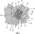
- elastomeric O-ring seals may be positioned along the exterior of the poppet valve 54 and oriented for engagement with a corresponding wall surface 96 which defines the recess 58 (see Figure 6 ).
- the seals 92, 94 prevent unwanted loss of pressure past the poppet valve 54 during, for example, pressure testing to verify proper landing of the tubing hanger 44 in tubing head spool 32.
- poppet stem 78 may comprise a portion 98 which extends from the valve body 76.
- the portion 98 is oriented for engagement with the landing surface 56 such that landing of the tubing hanger 44 in the tubing head spool 32 causes the landing surface 56 to engage portion 98 and to shift the poppet stem 78.
- the poppet stem 78 is shifted to the closed flow position, illustrated in Figure 4 , thus blocking flow through the poppet valve 54.
- the poppet stem 78 may have a conical region 100, e.g. a cone, having a seating surface 102 which seats against a corresponding seating surface 104, as further illustrated in Figure 5 , when the poppet valve 54 is shifted to the closed flow position.
- the corresponding seating surface 104 may be formed in retainer cap 80 and oriented for engagement with seating surface 102.
- the corresponding seating surface 104 may be located on valve body 76 or at other suitable locations.
- the seals 92, 94 work with the engaged seating surfaces 102, 104 to hold against pressure applied in pressure line 64.
- poppet valve 54 When poppet valve 54 is in the open flow position, pressure is not held and fluid flow is allowed to move past the cone 100 between seating surfaces 102 and 104. In the example illustrated, this open position fluid flow is allowed to flow past the poppet stem 78 and through a flow passage or passages 106 formed in poppet valve 54, e.g. through valve body 76.
- the flow passage(s) 106 allow the fluid to exit the tubing hanger 44.
- the flow passages 106 may be routed between a pair of the external seals 94 and through a side of the valve body 76.
- the flow passages 106 may be placed in fluid communication with a corresponding flow passage 108 routed through a portion of the tubing hanger 44, as illustrated in Figure 6 .
- the poppet stem 78 may be constructed as a two-piece poppet stem having a first stem piece 110 separated from a second stem piece 112 via a spring member 114.
- the spring member 114 may be in the form of Belleville washers or other suitable spring members which resist but allow some movement between the first and second stem pieces 110, 112.
- the use of spring member 114 between stem pieces 110, 112 accommodates part tolerances and debris without limiting the sealing capabilities of the seating surfaces 102 and 104. This approach adds flexibility to the structure and ensures the poppet seal is maintained in spite of differences in tolerances or debris on, for example, the landing surface 56.
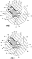
- poppet valve 54 another embodiment of poppet valve 54 is illustrated.
- components of the poppet valve 54 are arranged such that the retainer cap 80 holds the components of poppet valve 54 in recess 58.
- the retainer cap 80 may be secured to the subsea component/tubing hanger 44 via a threaded engagement 116 or by other suitable fastening mechanisms.
- the poppet stem 78 is again spring biased via spring 82 towards a normally open position, as illustrated in Figure 7 . In this position, the seating surface 102 remains unseated with respect to corresponding seating surface 104.
- the corresponding seating surface 104 is located along a back ring 118.
- the back ring 118 may comprise a flow passage 120 to accommodate flow between pressure line 64 and flow passages 122 through poppet stem 78.
- the back ring 118 may be mounted against spring member 114 to similarly provide flexibility for varying tolerances and debris.
- a seal 124 e.g. an O-ring seal, may be positioned between back ring 118 and the wall surface 96 defining recess 58.
- poppet stem 78 When the portion 98 of poppet stem 78 sufficiently engages landing surface 56 during proper landing of tubing hanger 44 in tubing head spool 32, the poppet stem 78 is shifted to the closed flow position as illustrated in Figure 8 . In this position, seating surface 102 is sealingly engaged with corresponding seating surface 104 to block flow from pressure line 64, thus enabling pressure testing to verify proper landing.
- the poppet valve 54 utilizes a single piece poppet stem 78 which is capable of bleeding pressure through itself without the addition of side porting and external seals.
- poppet valve 54 In tubing hanger applications, the various embodiments of poppet valve 54 are each able to provide an indication when the tubing hanger 44 has properly, e.g. completely, landed in the tubing head spool 32. When the tubing hanger 44 is properly landed, the poppet valve 54 is shifted from an open flow position to a closed flow position able to hold hydraulic pressure. As a result, pressure testing may be applied via pressure line 64 to verify proper landing without a visual indication.
- the poppet valve 54 is useful in positively confirming proper landing of the tubing hanger 44 prior to bore pressure tests and prior to locking of the tubing hanger 44 to the tubing head spool 32. Additionally, this type of verification system enables venting of the gallery 68 during running of the tubing hanger 44 down to the tubing head spool 32. The ability to hold pressure in the gallery 68 due to the closed poppet valve 54 also can be useful when the tubing hanger running tool 48 is recovered and re-run down to the tubing hanger 44. The closed poppet valve 54 enables pressure testing following stabbing of the tubing hanger running tool 48 into the tubing hanger 44. Furthermore, the normally open-position poppet valve 54 does not interfere with or build up/trap pressure during emergency unlatching and blowout preventer tests.
- this type of landing verification system may be used for a variety of components, including subsea equipment run through a riser and landed in a region which is not amenable to visual verification.
- the poppet valve based landing verification system also may be used with various communication systems and control systems to similarly verify when a desired landing has been achieved.
- the poppet valve 54 may be constructed in various configurations to enable shifting from an open flow position to a closed flow position upon proper landing. Additionally, the poppet valve 54 may be used in a variety of tubing hangers 44 and other types of subsea components which are landed in corresponding equipment. The pressure testing may be conducted through various pressure passages routed down to the poppet valve 54. Depending on the component configuration, the poppet valve 54 may be mounted in a variety of recesses or along a variety of other structures to enable engagement with a desired landing surface.
Landscapes
- Engineering & Computer Science (AREA)
- Geology (AREA)
- Life Sciences & Earth Sciences (AREA)
- Mining & Mineral Resources (AREA)
- Physics & Mathematics (AREA)
- Environmental & Geological Engineering (AREA)
- Fluid Mechanics (AREA)
- General Life Sciences & Earth Sciences (AREA)
- Geochemistry & Mineralogy (AREA)
- Geophysics (AREA)
- Mechanical Engineering (AREA)
- Lift Valve (AREA)
- Safety Valves (AREA)
- Indication Of The Valve Opening Or Closing Status (AREA)
- Fluid-Driven Valves (AREA)
Claims (14)
- System (20) zur Verwendung in einer Unterwasser-Bohrlochanwendung, umfassend:einen Steigrohr-Doppelflansch (32) mit einer Aufnahme (52) und einer Landefläche (56); undeinen zum Aufnehmen in der Aufnahme (52) des Steigrohr-Doppelflansches (32) bemessenen Steigrohrhänger (44), wobei der Steigrohrhänger (44) aufweist: ein für einen Eingriff mit der Landefläche (56) ausgerichtetes Tellerventil (54); und eine zum Tellerventil (54) geführte Druckleitung (64), dadurch gekennzeichnet, dass das Tellerventil (54) in eine offene Durchflussrichtung vorgespannt ist, um einen Fluiddurchfluss in der Druckleitung (64) entlang und durch das Tellerventil (54) hindurch vor dem Ablanden des Tellerventils (54) gegen die Landefläche (56) zu ermöglichen.
- System gemäß Anspruch 1, wobei der Steigrohrhänger (44) eine für einen Eingriff mit der Landefläche (56) des Steigrohr-Doppelflansches (32) orientierte Steigrohrhänger-Landefläche (60) umfasst.
- System gemäß Anspruch 1, ferner umfassend einen Verriegelungsmechanismus (72) zwischen dem Steigrohr-Doppelflansch (32) und dem Steigrohrhänger (44).
- System gemäß Anspruch 1, ferner umfassend ein lösbar mit dem Steigrohrhänger (44) gekoppeltes Steigrohrhänger-Einbauwerkzeug (48).
- System gemäß Anspruch 1, wobei das Tellerventil (54) einen Ventilkörper (76), eine zum selektiven Blockieren oder Hindurchlassen von Fluiddurchfluss durch das Tellerventil (54) bewegliche Tellerventilspindel (78), eine Haltekappe (80) und eine zum Vorspannen der Tellerventilspindel (78) in eine offene Durchflussstellung positionierte Feder (82) umfasst.
- System gemäß Anspruch 5, wobei sich ein Abschnitt (98) der Tellerventilspindel (78) aus dem Ventilkörper (76) erstreckt, wobei der Abschnitt (98) für einen Eingriff mit der Landefläche (56) orientiert ist, so dass das Ablanden des Steigrohrhängers (44) im Steigrohrdoppelflansch (32) die Tellerventilspindel (78) in eine Stellung verschiebt, die den Durchfluss durch das Tellerventil (54) blockiert.
- System gemäß Anspruch 6, wobei das Tellerventil (54) in einer im Steigrohrhänger (44) ausgebildeten Ausnehmung (58) aufgenommen wird, wobei sich die Ausnehmung (58) in fluidkommunizierender Verbindung mit der Druckleitung (66) befindet.
- System gemäß Anspruch 7, wobei das Tellerventil (54) wenigstens eine Elastomerdichtung (92) umfasst, die zum Abdichten zwischen dem Tellerventil (54) und einer die Ausnehmung (58) ausbildenden Wandungsfläche (96) positioniert ist.
- System gemäß Anspruch 8, wobei die Tellerventilspindel (78) ein erstes Spindelstück (110) umfasst, das mithilfe eines Federelements (114) von einem zweiten Spindelstück (112) getrennt ist.
- System gemäß Anspruch 5, wobei die Tellerventilspindel (78) einen Kegel (100) umfasst, der eine Sitzfläche (104) aufweist, die sich gegen die Haltekappe (80) anlegt, wenn das Tellerventil (54) in eine geschlossene Durchflussstellung verschoben wird, die einen Fluiddurchfluss durch dasselbe blockiert.
- Verfahren, umfassend:Platzieren eines Tellerventils (54) in einem Steigrohrhänger (44), der eine sich zum Tellerventil (54) erstreckende Druckleitung (66) aufweist;Halten des Tellerventils (54) in einer offenen Durchflussstellung, während der Steigrohrhänger (44) zu einem Steigrohr-Doppelflansch (32) hin bewegt wird;Ablanden des Steigrohrhängers (44) im Steigrohr-Doppelflansch (32);Verwenden einer Landefläche (56) im Steigrohr-Doppelflansch (32), um das Tellerventil (54) nach dem richtigen Ablanden in eine geschlossene Durchflussstellung zu verschieben; undDruckbeaufschlagen der Druckleitung (66), um zu prüfen, ob der Steigrohrhänger (44) richtig im Steigrohr-Doppelflansch (32) abgelandet ist.
- System gemäß Anspruch 11, ferner umfassend ein Bewegen des Steigrohrhängers (44) zum Steigrohr-Doppelflansch (32) hin mit einem Steigrohrhänger-Einbauwerkzeug (48).
- Verfahren gemäß Anspruch 11, wobei das Verwenden der Landefläche (56) ein Ineingriffbringen der Landefläche (56) mit einem sich aus einem Ventilkörper (76) des Tellerventils (54) erstreckenden Abschnitt einer Tellerventilspindel (78) umfasst.
- Verfahren gemäß Anspruch 13, ferner umfassend ein Verhindern eines Störens des Ablandens des Steigrohrhängers (44) im Steigrohr-Doppelflansch (32) durch Ausbilden der Tellerventilspindel mit zwei durch ein Federelement (114) getrennten Stücken (110, 112).
Applications Claiming Priority (1)
| Application Number | Priority Date | Filing Date | Title |
|---|---|---|---|
| US15/813,460 US10415329B2 (en) | 2017-11-15 | 2017-11-15 | Subsea system with landing indication |
Publications (3)
| Publication Number | Publication Date |
|---|---|
| EP3486426A2 EP3486426A2 (de) | 2019-05-22 |
| EP3486426A3 EP3486426A3 (de) | 2019-07-03 |
| EP3486426B1 true EP3486426B1 (de) | 2020-10-21 |
Family
ID=64316415
Family Applications (1)
| Application Number | Title | Priority Date | Filing Date |
|---|---|---|---|
| EP18206274.5A Active EP3486426B1 (de) | 2017-11-15 | 2018-11-14 | Unterwassersystem mit landeanzeige |
Country Status (2)
| Country | Link |
|---|---|
| US (1) | US10415329B2 (de) |
| EP (1) | EP3486426B1 (de) |
Families Citing this family (2)
| Publication number | Priority date | Publication date | Assignee | Title |
|---|---|---|---|---|
| US10655454B2 (en) * | 2016-03-04 | 2020-05-19 | Aker Solutions As | Subsea well equipment landing indicator and locking indicator |
| US11719065B2 (en) * | 2020-11-13 | 2023-08-08 | Onesubsea Ip Uk Limited | Configurable coupling assembly |
Family Cites Families (8)
| Publication number | Priority date | Publication date | Assignee | Title |
|---|---|---|---|---|
| US4300750A (en) * | 1980-02-11 | 1981-11-17 | Armco Inc. | Position indicating valves |
| US4300637A (en) * | 1980-02-11 | 1981-11-17 | Armco Inc. | Tool for remotely determining the position of a device in an underwater well assembly |
| US4862426A (en) * | 1987-12-08 | 1989-08-29 | Cameron Iron Works Usa, Inc. | Method and apparatus for operating equipment in a remote location |
| NO322809B1 (no) * | 2001-06-15 | 2006-12-11 | Schlumberger Technology Bv | Anordning og fremgangsmate for a overvake og styre utplassering av utstyr pa havbunnen |
| US8322428B2 (en) * | 2009-10-09 | 2012-12-04 | Vetco Gray Inc. | Casing hanger nesting indicator |
| US8567493B2 (en) * | 2010-04-09 | 2013-10-29 | Cameron International Corporation | Tubing hanger running tool with integrated landing features |
| US10077622B2 (en) * | 2011-05-19 | 2018-09-18 | Vetco Gray, LLC | Tubing hanger setting confirmation system |
| US10655454B2 (en) * | 2016-03-04 | 2020-05-19 | Aker Solutions As | Subsea well equipment landing indicator and locking indicator |
-
2017
- 2017-11-15 US US15/813,460 patent/US10415329B2/en active Active
-
2018
- 2018-11-14 EP EP18206274.5A patent/EP3486426B1/de active Active
Non-Patent Citations (1)
| Title |
|---|
| None * |
Also Published As
| Publication number | Publication date |
|---|---|
| EP3486426A2 (de) | 2019-05-22 |
| EP3486426A3 (de) | 2019-07-03 |
| US10415329B2 (en) | 2019-09-17 |
| US20190145196A1 (en) | 2019-05-16 |
Similar Documents
| Publication | Publication Date | Title |
|---|---|---|
| US8251147B2 (en) | Method and apparatus for continuously injecting fluid in a wellbore while maintaining safety valve operation | |
| US8230928B2 (en) | Low profile internal tree cap | |
| EP3012400B1 (de) | Ausfallsicheres gesteuertes unterirdisches sicherheitsventil | |
| US10738556B2 (en) | Open/close outlet internal hydraulic device | |
| US11828127B2 (en) | Tubing hanger with shiftable annulus seal | |
| US20180313187A1 (en) | Single body choke line and kill line valves | |
| US9810336B2 (en) | Subsea BOP control system with dual-action check valve | |
| US20140060852A1 (en) | Pressure Testing Valve and Method of Using the Same | |
| US10273775B2 (en) | Apparatus and method for testing a blowout preventer | |
| EP3486426B1 (de) | Unterwassersystem mit landeanzeige | |
| US20050167118A1 (en) | Tubing annulus valve | |
| US11149511B2 (en) | Seal assembly running tools and methods | |
| US20180038190A1 (en) | Method and apparatus to effect injection of fluids into a subsea horizontal tree | |
| US5226478A (en) | Cement port closure sleeve for a subsea well | |
| US10260305B2 (en) | Completion system with external gate valve | |
| US6715555B2 (en) | Subsea well production system | |
| US10161244B2 (en) | System and methodology using annulus access valve | |
| US20200291750A1 (en) | Method of intervention in a failed deep-set subsurface safety valve in a deepwater or ultra-deepwater subsea well using a light intervention vessel | |
| CA2814901C (en) | Failsafe hydrostatic vent | |
| US20250230744A1 (en) | Pressure testing a wellhead | |
| GB2119831A (en) | Downhole safety systems for use while servicing wells | |
| NO348560B1 (en) | Method of operating a subsea module and downhole tool string | |
| US9194203B1 (en) | Subsea latch tool for connecting subsea components | |
| BR112021011122B1 (pt) | Sistema e método | |
| GB2378724A (en) | Retainer valve system for controlling fluid flow through a blowout preventer |
Legal Events
| Date | Code | Title | Description |
|---|---|---|---|
| PUAI | Public reference made under article 153(3) epc to a published international application that has entered the european phase |
Free format text: ORIGINAL CODE: 0009012 |
|
| STAA | Information on the status of an ep patent application or granted ep patent |
Free format text: STATUS: THE APPLICATION HAS BEEN PUBLISHED |
|
| AK | Designated contracting states |
Kind code of ref document: A2 Designated state(s): AL AT BE BG CH CY CZ DE DK EE ES FI FR GB GR HR HU IE IS IT LI LT LU LV MC MK MT NL NO PL PT RO RS SE SI SK SM TR |
|
| AX | Request for extension of the european patent |
Extension state: BA ME |
|
| PUAL | Search report despatched |
Free format text: ORIGINAL CODE: 0009013 |
|
| AK | Designated contracting states |
Kind code of ref document: A3 Designated state(s): AL AT BE BG CH CY CZ DE DK EE ES FI FR GB GR HR HU IE IS IT LI LT LU LV MC MK MT NL NO PL PT RO RS SE SI SK SM TR |
|
| AX | Request for extension of the european patent |
Extension state: BA ME |
|
| RIC1 | Information provided on ipc code assigned before grant |
Ipc: E21B 34/04 20060101ALI20190529BHEP Ipc: E21B 33/043 20060101AFI20190529BHEP |
|
| STAA | Information on the status of an ep patent application or granted ep patent |
Free format text: STATUS: REQUEST FOR EXAMINATION WAS MADE |
|
| 17P | Request for examination filed |
Effective date: 20191219 |
|
| RBV | Designated contracting states (corrected) |
Designated state(s): AL AT BE BG CH CY CZ DE DK EE ES FI FR GB GR HR HU IE IS IT LI LT LU LV MC MK MT NL NO PL PT RO RS SE SI SK SM TR |
|
| GRAP | Despatch of communication of intention to grant a patent |
Free format text: ORIGINAL CODE: EPIDOSNIGR1 |
|
| STAA | Information on the status of an ep patent application or granted ep patent |
Free format text: STATUS: GRANT OF PATENT IS INTENDED |
|
| INTG | Intention to grant announced |
Effective date: 20200519 |
|
| GRAS | Grant fee paid |
Free format text: ORIGINAL CODE: EPIDOSNIGR3 |
|
| GRAA | (expected) grant |
Free format text: ORIGINAL CODE: 0009210 |
|
| STAA | Information on the status of an ep patent application or granted ep patent |
Free format text: STATUS: THE PATENT HAS BEEN GRANTED |
|
| AK | Designated contracting states |
Kind code of ref document: B1 Designated state(s): AL AT BE BG CH CY CZ DE DK EE ES FI FR GB GR HR HU IE IS IT LI LT LU LV MC MK MT NL NO PL PT RO RS SE SI SK SM TR |
|
| REG | Reference to a national code |
Ref country code: GB Ref legal event code: FG4D |
|
| REG | Reference to a national code |
Ref country code: CH Ref legal event code: EP |
|
| REG | Reference to a national code |
Ref country code: DE Ref legal event code: R096 Ref document number: 602018008907 Country of ref document: DE |
|
| REG | Reference to a national code |
Ref country code: IE Ref legal event code: FG4D |
|
| REG | Reference to a national code |
Ref country code: AT Ref legal event code: REF Ref document number: 1326029 Country of ref document: AT Kind code of ref document: T Effective date: 20201115 |
|
| REG | Reference to a national code |
Ref country code: AT Ref legal event code: MK05 Ref document number: 1326029 Country of ref document: AT Kind code of ref document: T Effective date: 20201021 |
|
| REG | Reference to a national code |
Ref country code: NL Ref legal event code: MP Effective date: 20201021 |
|
| REG | Reference to a national code |
Ref country code: NO Ref legal event code: T2 Effective date: 20201021 |
|
| PG25 | Lapsed in a contracting state [announced via postgrant information from national office to epo] |
Ref country code: GR Free format text: LAPSE BECAUSE OF FAILURE TO SUBMIT A TRANSLATION OF THE DESCRIPTION OR TO PAY THE FEE WITHIN THE PRESCRIBED TIME-LIMIT Effective date: 20210122 Ref country code: PT Free format text: LAPSE BECAUSE OF FAILURE TO SUBMIT A TRANSLATION OF THE DESCRIPTION OR TO PAY THE FEE WITHIN THE PRESCRIBED TIME-LIMIT Effective date: 20210222 Ref country code: RS Free format text: LAPSE BECAUSE OF FAILURE TO SUBMIT A TRANSLATION OF THE DESCRIPTION OR TO PAY THE FEE WITHIN THE PRESCRIBED TIME-LIMIT Effective date: 20201021 Ref country code: FI Free format text: LAPSE BECAUSE OF FAILURE TO SUBMIT A TRANSLATION OF THE DESCRIPTION OR TO PAY THE FEE WITHIN THE PRESCRIBED TIME-LIMIT Effective date: 20201021 |
|
| REG | Reference to a national code |
Ref country code: LT Ref legal event code: MG4D |
|
| PG25 | Lapsed in a contracting state [announced via postgrant information from national office to epo] |
Ref country code: BG Free format text: LAPSE BECAUSE OF FAILURE TO SUBMIT A TRANSLATION OF THE DESCRIPTION OR TO PAY THE FEE WITHIN THE PRESCRIBED TIME-LIMIT Effective date: 20210121 Ref country code: IS Free format text: LAPSE BECAUSE OF FAILURE TO SUBMIT A TRANSLATION OF THE DESCRIPTION OR TO PAY THE FEE WITHIN THE PRESCRIBED TIME-LIMIT Effective date: 20210221 Ref country code: LV Free format text: LAPSE BECAUSE OF FAILURE TO SUBMIT A TRANSLATION OF THE DESCRIPTION OR TO PAY THE FEE WITHIN THE PRESCRIBED TIME-LIMIT Effective date: 20201021 Ref country code: PL Free format text: LAPSE BECAUSE OF FAILURE TO SUBMIT A TRANSLATION OF THE DESCRIPTION OR TO PAY THE FEE WITHIN THE PRESCRIBED TIME-LIMIT Effective date: 20201021 Ref country code: SE Free format text: LAPSE BECAUSE OF FAILURE TO SUBMIT A TRANSLATION OF THE DESCRIPTION OR TO PAY THE FEE WITHIN THE PRESCRIBED TIME-LIMIT Effective date: 20201021 Ref country code: ES Free format text: LAPSE BECAUSE OF FAILURE TO SUBMIT A TRANSLATION OF THE DESCRIPTION OR TO PAY THE FEE WITHIN THE PRESCRIBED TIME-LIMIT Effective date: 20201021 Ref country code: AT Free format text: LAPSE BECAUSE OF FAILURE TO SUBMIT A TRANSLATION OF THE DESCRIPTION OR TO PAY THE FEE WITHIN THE PRESCRIBED TIME-LIMIT Effective date: 20201021 |
|
| REG | Reference to a national code |
Ref country code: DE Ref legal event code: R119 Ref document number: 602018008907 Country of ref document: DE |
|
| PG25 | Lapsed in a contracting state [announced via postgrant information from national office to epo] |
Ref country code: HR Free format text: LAPSE BECAUSE OF FAILURE TO SUBMIT A TRANSLATION OF THE DESCRIPTION OR TO PAY THE FEE WITHIN THE PRESCRIBED TIME-LIMIT Effective date: 20201021 Ref country code: NL Free format text: LAPSE BECAUSE OF FAILURE TO SUBMIT A TRANSLATION OF THE DESCRIPTION OR TO PAY THE FEE WITHIN THE PRESCRIBED TIME-LIMIT Effective date: 20201021 |
|
| PG25 | Lapsed in a contracting state [announced via postgrant information from national office to epo] |
Ref country code: EE Free format text: LAPSE BECAUSE OF FAILURE TO SUBMIT A TRANSLATION OF THE DESCRIPTION OR TO PAY THE FEE WITHIN THE PRESCRIBED TIME-LIMIT Effective date: 20201021 Ref country code: CZ Free format text: LAPSE BECAUSE OF FAILURE TO SUBMIT A TRANSLATION OF THE DESCRIPTION OR TO PAY THE FEE WITHIN THE PRESCRIBED TIME-LIMIT Effective date: 20201021 Ref country code: SK Free format text: LAPSE BECAUSE OF FAILURE TO SUBMIT A TRANSLATION OF THE DESCRIPTION OR TO PAY THE FEE WITHIN THE PRESCRIBED TIME-LIMIT Effective date: 20201021 Ref country code: SM Free format text: LAPSE BECAUSE OF FAILURE TO SUBMIT A TRANSLATION OF THE DESCRIPTION OR TO PAY THE FEE WITHIN THE PRESCRIBED TIME-LIMIT Effective date: 20201021 Ref country code: RO Free format text: LAPSE BECAUSE OF FAILURE TO SUBMIT A TRANSLATION OF THE DESCRIPTION OR TO PAY THE FEE WITHIN THE PRESCRIBED TIME-LIMIT Effective date: 20201021 Ref country code: LT Free format text: LAPSE BECAUSE OF FAILURE TO SUBMIT A TRANSLATION OF THE DESCRIPTION OR TO PAY THE FEE WITHIN THE PRESCRIBED TIME-LIMIT Effective date: 20201021 Ref country code: MC Free format text: LAPSE BECAUSE OF FAILURE TO SUBMIT A TRANSLATION OF THE DESCRIPTION OR TO PAY THE FEE WITHIN THE PRESCRIBED TIME-LIMIT Effective date: 20201021 Ref country code: LU Free format text: LAPSE BECAUSE OF NON-PAYMENT OF DUE FEES Effective date: 20201114 |
|
| REG | Reference to a national code |
Ref country code: BE Ref legal event code: MM Effective date: 20201130 |
|
| PLBE | No opposition filed within time limit |
Free format text: ORIGINAL CODE: 0009261 |
|
| STAA | Information on the status of an ep patent application or granted ep patent |
Free format text: STATUS: NO OPPOSITION FILED WITHIN TIME LIMIT |
|
| PG25 | Lapsed in a contracting state [announced via postgrant information from national office to epo] |
Ref country code: DK Free format text: LAPSE BECAUSE OF FAILURE TO SUBMIT A TRANSLATION OF THE DESCRIPTION OR TO PAY THE FEE WITHIN THE PRESCRIBED TIME-LIMIT Effective date: 20201021 |
|
| 26N | No opposition filed |
Effective date: 20210722 |
|
| PG25 | Lapsed in a contracting state [announced via postgrant information from national office to epo] |
Ref country code: IE Free format text: LAPSE BECAUSE OF NON-PAYMENT OF DUE FEES Effective date: 20201114 Ref country code: FR Free format text: LAPSE BECAUSE OF NON-PAYMENT OF DUE FEES Effective date: 20201221 Ref country code: IT Free format text: LAPSE BECAUSE OF FAILURE TO SUBMIT A TRANSLATION OF THE DESCRIPTION OR TO PAY THE FEE WITHIN THE PRESCRIBED TIME-LIMIT Effective date: 20201021 Ref country code: AL Free format text: LAPSE BECAUSE OF FAILURE TO SUBMIT A TRANSLATION OF THE DESCRIPTION OR TO PAY THE FEE WITHIN THE PRESCRIBED TIME-LIMIT Effective date: 20201021 |
|
| PG25 | Lapsed in a contracting state [announced via postgrant information from national office to epo] |
Ref country code: DE Free format text: LAPSE BECAUSE OF NON-PAYMENT OF DUE FEES Effective date: 20210601 Ref country code: SI Free format text: LAPSE BECAUSE OF FAILURE TO SUBMIT A TRANSLATION OF THE DESCRIPTION OR TO PAY THE FEE WITHIN THE PRESCRIBED TIME-LIMIT Effective date: 20201021 |
|
| PG25 | Lapsed in a contracting state [announced via postgrant information from national office to epo] |
Ref country code: IS Free format text: LAPSE BECAUSE OF FAILURE TO SUBMIT A TRANSLATION OF THE DESCRIPTION OR TO PAY THE FEE WITHIN THE PRESCRIBED TIME-LIMIT Effective date: 20210221 Ref country code: TR Free format text: LAPSE BECAUSE OF FAILURE TO SUBMIT A TRANSLATION OF THE DESCRIPTION OR TO PAY THE FEE WITHIN THE PRESCRIBED TIME-LIMIT Effective date: 20201021 Ref country code: MT Free format text: LAPSE BECAUSE OF FAILURE TO SUBMIT A TRANSLATION OF THE DESCRIPTION OR TO PAY THE FEE WITHIN THE PRESCRIBED TIME-LIMIT Effective date: 20201021 Ref country code: CY Free format text: LAPSE BECAUSE OF FAILURE TO SUBMIT A TRANSLATION OF THE DESCRIPTION OR TO PAY THE FEE WITHIN THE PRESCRIBED TIME-LIMIT Effective date: 20201021 |
|
| PG25 | Lapsed in a contracting state [announced via postgrant information from national office to epo] |
Ref country code: MK Free format text: LAPSE BECAUSE OF FAILURE TO SUBMIT A TRANSLATION OF THE DESCRIPTION OR TO PAY THE FEE WITHIN THE PRESCRIBED TIME-LIMIT Effective date: 20201021 |
|
| REG | Reference to a national code |
Ref country code: CH Ref legal event code: PL |
|
| PG25 | Lapsed in a contracting state [announced via postgrant information from national office to epo] |
Ref country code: BE Free format text: LAPSE BECAUSE OF NON-PAYMENT OF DUE FEES Effective date: 20201130 |
|
| PG25 | Lapsed in a contracting state [announced via postgrant information from national office to epo] |
Ref country code: LI Free format text: LAPSE BECAUSE OF NON-PAYMENT OF DUE FEES Effective date: 20211130 Ref country code: CH Free format text: LAPSE BECAUSE OF NON-PAYMENT OF DUE FEES Effective date: 20211130 |
|
| P01 | Opt-out of the competence of the unified patent court (upc) registered |
Effective date: 20231212 |
|
| PGFP | Annual fee paid to national office [announced via postgrant information from national office to epo] |
Ref country code: GB Payment date: 20250925 Year of fee payment: 8 |
|
| PGFP | Annual fee paid to national office [announced via postgrant information from national office to epo] |
Ref country code: NO Payment date: 20251113 Year of fee payment: 8 |