EP3486221B1 - Electrolyzed water generation device - Google Patents
Electrolyzed water generation device Download PDFInfo
- Publication number
- EP3486221B1 EP3486221B1 EP17831091.8A EP17831091A EP3486221B1 EP 3486221 B1 EP3486221 B1 EP 3486221B1 EP 17831091 A EP17831091 A EP 17831091A EP 3486221 B1 EP3486221 B1 EP 3486221B1
- Authority
- EP
- European Patent Office
- Prior art keywords
- power feeder
- switching
- flow passage
- water
- chamber
- Prior art date
- Legal status (The legal status is an assumption and is not a legal conclusion. Google has not performed a legal analysis and makes no representation as to the accuracy of the status listed.)
- Active
Links
- XLYOFNOQVPJJNP-UHFFFAOYSA-N water Substances O XLYOFNOQVPJJNP-UHFFFAOYSA-N 0.000 title claims description 222
- 238000005868 electrolysis reaction Methods 0.000 claims description 40
- 238000001514 detection method Methods 0.000 claims description 20
- 239000012528 membrane Substances 0.000 claims description 9
- UFHFLCQGNIYNRP-UHFFFAOYSA-N Hydrogen Chemical compound [H][H] UFHFLCQGNIYNRP-UHFFFAOYSA-N 0.000 description 21
- 239000001257 hydrogen Substances 0.000 description 19
- 229910052739 hydrogen Inorganic materials 0.000 description 19
- 230000006870 function Effects 0.000 description 11
- 238000000746 purification Methods 0.000 description 10
- 230000001105 regulatory effect Effects 0.000 description 9
- 239000008213 purified water Substances 0.000 description 6
- 230000002829 reductive effect Effects 0.000 description 6
- 238000000034 method Methods 0.000 description 5
- 229910021645 metal ion Inorganic materials 0.000 description 4
- 238000011144 upstream manufacturing Methods 0.000 description 4
- 239000002253 acid Substances 0.000 description 3
- 230000007423 decrease Effects 0.000 description 3
- 230000001419 dependent effect Effects 0.000 description 3
- 238000007599 discharging Methods 0.000 description 3
- 239000008399 tap water Substances 0.000 description 3
- 235000020679 tap water Nutrition 0.000 description 3
- 238000010411 cooking Methods 0.000 description 2
- 239000007789 gas Substances 0.000 description 2
- 229910052500 inorganic mineral Inorganic materials 0.000 description 2
- 239000011707 mineral Substances 0.000 description 2
- 230000002035 prolonged effect Effects 0.000 description 2
- OYPRJOBELJOOCE-UHFFFAOYSA-N Calcium Chemical compound [Ca] OYPRJOBELJOOCE-UHFFFAOYSA-N 0.000 description 1
- BHPQYMZQTOCNFJ-UHFFFAOYSA-N Calcium cation Chemical compound [Ca+2] BHPQYMZQTOCNFJ-UHFFFAOYSA-N 0.000 description 1
- MYMOFIZGZYHOMD-UHFFFAOYSA-N Dioxygen Chemical compound O=O MYMOFIZGZYHOMD-UHFFFAOYSA-N 0.000 description 1
- JLVVSXFLKOJNIY-UHFFFAOYSA-N Magnesium ion Chemical compound [Mg+2] JLVVSXFLKOJNIY-UHFFFAOYSA-N 0.000 description 1
- 229910052791 calcium Inorganic materials 0.000 description 1
- 239000011575 calcium Substances 0.000 description 1
- 229910001424 calcium ion Inorganic materials 0.000 description 1
- 238000004140 cleaning Methods 0.000 description 1
- 230000001276 controlling effect Effects 0.000 description 1
- 238000010586 diagram Methods 0.000 description 1
- 229910001882 dioxygen Inorganic materials 0.000 description 1
- 230000035622 drinking Effects 0.000 description 1
- 235000020188 drinking water Nutrition 0.000 description 1
- 239000003651 drinking water Substances 0.000 description 1
- 230000000694 effects Effects 0.000 description 1
- 239000003673 groundwater Substances 0.000 description 1
- 230000010365 information processing Effects 0.000 description 1
- 150000002500 ions Chemical class 0.000 description 1
- 229910001425 magnesium ion Inorganic materials 0.000 description 1
- 239000000203 mixture Substances 0.000 description 1
- 235000020681 well water Nutrition 0.000 description 1
- 239000002349 well water Substances 0.000 description 1
Images

Classifications
-
- C—CHEMISTRY; METALLURGY
- C02—TREATMENT OF WATER, WASTE WATER, SEWAGE, OR SLUDGE
- C02F—TREATMENT OF WATER, WASTE WATER, SEWAGE, OR SLUDGE
- C02F1/00—Treatment of water, waste water, or sewage
- C02F1/46—Treatment of water, waste water, or sewage by electrochemical methods
- C02F1/461—Treatment of water, waste water, or sewage by electrochemical methods by electrolysis
- C02F1/467—Treatment of water, waste water, or sewage by electrochemical methods by electrolysis by electrochemical disinfection; by electrooxydation or by electroreduction
- C02F1/4676—Treatment of water, waste water, or sewage by electrochemical methods by electrolysis by electrochemical disinfection; by electrooxydation or by electroreduction by electroreduction
-
- C—CHEMISTRY; METALLURGY
- C02—TREATMENT OF WATER, WASTE WATER, SEWAGE, OR SLUDGE
- C02F—TREATMENT OF WATER, WASTE WATER, SEWAGE, OR SLUDGE
- C02F1/00—Treatment of water, waste water, or sewage
- C02F1/46—Treatment of water, waste water, or sewage by electrochemical methods
-
- C—CHEMISTRY; METALLURGY
- C02—TREATMENT OF WATER, WASTE WATER, SEWAGE, OR SLUDGE
- C02F—TREATMENT OF WATER, WASTE WATER, SEWAGE, OR SLUDGE
- C02F1/00—Treatment of water, waste water, or sewage
- C02F1/46—Treatment of water, waste water, or sewage by electrochemical methods
- C02F1/461—Treatment of water, waste water, or sewage by electrochemical methods by electrolysis
- C02F1/46104—Devices therefor; Their operating or servicing
- C02F1/4618—Devices therefor; Their operating or servicing for producing "ionised" acidic or basic water
-
- C—CHEMISTRY; METALLURGY
- C02—TREATMENT OF WATER, WASTE WATER, SEWAGE, OR SLUDGE
- C02F—TREATMENT OF WATER, WASTE WATER, SEWAGE, OR SLUDGE
- C02F1/00—Treatment of water, waste water, or sewage
- C02F1/46—Treatment of water, waste water, or sewage by electrochemical methods
- C02F1/461—Treatment of water, waste water, or sewage by electrochemical methods by electrolysis
- C02F1/46104—Devices therefor; Their operating or servicing
- C02F1/46109—Electrodes
- C02F2001/46119—Cleaning the electrodes
-
- C—CHEMISTRY; METALLURGY
- C02—TREATMENT OF WATER, WASTE WATER, SEWAGE, OR SLUDGE
- C02F—TREATMENT OF WATER, WASTE WATER, SEWAGE, OR SLUDGE
- C02F2201/00—Apparatus for treatment of water, waste water or sewage
- C02F2201/46—Apparatus for electrochemical processes
- C02F2201/461—Electrolysis apparatus
- C02F2201/46105—Details relating to the electrolytic devices
- C02F2201/46115—Electrolytic cell with membranes or diaphragms
-
- C—CHEMISTRY; METALLURGY
- C02—TREATMENT OF WATER, WASTE WATER, SEWAGE, OR SLUDGE
- C02F—TREATMENT OF WATER, WASTE WATER, SEWAGE, OR SLUDGE
- C02F2201/00—Apparatus for treatment of water, waste water or sewage
- C02F2201/46—Apparatus for electrochemical processes
- C02F2201/461—Electrolysis apparatus
- C02F2201/46105—Details relating to the electrolytic devices
- C02F2201/4612—Controlling or monitoring
- C02F2201/46125—Electrical variables
- C02F2201/4613—Inversing polarity
-
- C—CHEMISTRY; METALLURGY
- C02—TREATMENT OF WATER, WASTE WATER, SEWAGE, OR SLUDGE
- C02F—TREATMENT OF WATER, WASTE WATER, SEWAGE, OR SLUDGE
- C02F2201/00—Apparatus for treatment of water, waste water or sewage
- C02F2201/46—Apparatus for electrochemical processes
- C02F2201/461—Electrolysis apparatus
- C02F2201/46105—Details relating to the electrolytic devices
- C02F2201/4612—Controlling or monitoring
- C02F2201/46125—Electrical variables
- C02F2201/46135—Voltage
-
- C—CHEMISTRY; METALLURGY
- C02—TREATMENT OF WATER, WASTE WATER, SEWAGE, OR SLUDGE
- C02F—TREATMENT OF WATER, WASTE WATER, SEWAGE, OR SLUDGE
- C02F2201/00—Apparatus for treatment of water, waste water or sewage
- C02F2201/46—Apparatus for electrochemical processes
- C02F2201/461—Electrolysis apparatus
- C02F2201/46105—Details relating to the electrolytic devices
- C02F2201/4612—Controlling or monitoring
- C02F2201/46125—Electrical variables
- C02F2201/4614—Current
-
- C—CHEMISTRY; METALLURGY
- C02—TREATMENT OF WATER, WASTE WATER, SEWAGE, OR SLUDGE
- C02F—TREATMENT OF WATER, WASTE WATER, SEWAGE, OR SLUDGE
- C02F2201/00—Apparatus for treatment of water, waste water or sewage
- C02F2201/46—Apparatus for electrochemical processes
- C02F2201/461—Electrolysis apparatus
- C02F2201/46105—Details relating to the electrolytic devices
- C02F2201/4612—Controlling or monitoring
- C02F2201/46145—Fluid flow
-
- Y—GENERAL TAGGING OF NEW TECHNOLOGICAL DEVELOPMENTS; GENERAL TAGGING OF CROSS-SECTIONAL TECHNOLOGIES SPANNING OVER SEVERAL SECTIONS OF THE IPC; TECHNICAL SUBJECTS COVERED BY FORMER USPC CROSS-REFERENCE ART COLLECTIONS [XRACs] AND DIGESTS
- Y02—TECHNOLOGIES OR APPLICATIONS FOR MITIGATION OR ADAPTATION AGAINST CLIMATE CHANGE
- Y02E—REDUCTION OF GREENHOUSE GAS [GHG] EMISSIONS, RELATED TO ENERGY GENERATION, TRANSMISSION OR DISTRIBUTION
- Y02E60/00—Enabling technologies; Technologies with a potential or indirect contribution to GHG emissions mitigation
- Y02E60/30—Hydrogen technology
- Y02E60/36—Hydrogen production from non-carbon containing sources, e.g. by water electrolysis
Definitions
- the present invention relates to an electrolyzed water generation device for generating electrolyzed hydrogen water by electrolyzing water.
- an electrolyzed water generation device which is provided with an electrolytic cell having an anode chamber and a cathode chamber which are divided with a membrane and which electrolyzes raw water, such as tap water, to be supplied to the electrolytic cell (for example, see Patent documents 1 and 2).
- electrolyzed hydrogen water electrolyzed reduction water
- the electrolyzed water generation device immediately after starting water discharge, water remaining in the electrolytic cell is discharged without being sufficiently electrolyzed in some cases. Therefore, it is desirable not to use water until predetermined time passes from the start of the water discharge (for example, for several seconds) passes.
- metal ions such as calcium ion and magnesium ion
- These metal ions are hard to be removed with a filter and the like.
- the metal ions enter the electrolytic cell, the metal ions are deposited as scale inside a cathode chamber including a power feeder or inside a flow passage connected to the downstream side of the cathode chamber.
- an electrolyzed water generation device which is configured so that the adhesion of scale to power feeders arranged inside an electrolytic cell is suppressed by switching the polarities of the power feeders as appropriate after stopping electrolysis,
- the polarities of the power feeders are switched, the polarities are switched by operating a flow passage switching valve to synchronize upstream and downstream channels of the electrolytic cell, whereby electrolyzed water of the same type as that before the switching can be discharged from a water discharge port, so that an improvement of the usability is achieved.
- the present invention has been devised in view of the above-described circumstances. It is a main object of the present invention to provide an electrolyzed water generation device capable of improving the usability while suppressing the adhesion of scale to a power feeder and reducing discarded water.
- the present invention is an electrolyzed water generation device provided with an electrolytic chamber to which water to be electrolyzed is supplied, a first power feeder and a second power feeder disposed facing each other in the electrolytic chamber, and a membrane arranged between the first power feeder and the second power feeder and dividing the electrolytic chamber into a first polar chamber on the side of the first power feeder and a second polar chamber on the side of the second power feeder, and characterized in that the electrolyzed water generation device is further provided with a first flow passage delivering electrolyzed water generated in one of the first polar chamber and the second polar chamber to a first water discharge port, a second flow passage delivering electrolyzed water generated in the other one of the first polar chamber and the second polar chamber to a second water discharge port, a flow passage switching valve switching connections of the first polar chamber and the second polar chamber to the first flow passage and the second flow passage, a polarity switching unit switching the polarities of the first power feeder and the second power feeder, a determination unit
- the determination unit integrates electrolysis time in the electrolytic chamber and determines that the switching timing arrives when the time passes after the electrolysis is performed by the number of times or more in the electrolytic chamber without the polarities being switched and the integrated electrolysis time reaches a predetermined threshold value.
- the electrolyzed water generation device is further provided with a current detection unit detecting a current to be supplied to the first power feeder and the second power feeder and the determination unit changes the number of times based on an integrated value of the currents after switching the polarity and the flow passage.
- the determination unit changes the time based on the integrated value of the currents after switching the polarity and the flow passage in the electrolyzed water generation device according to the present invention.
- the electrolyzed water generation device is further provided with a voltage detection unit detecting a voltage to be applied to the first power feeder and the second power feeder and the determination unit changes the number of times based on a ratio of the voltage to the current after switching the polarity and the flow passage.
- the determination unit changes the time based on the ratio of the voltage to the current in the electrolyzed water generation device according to the present invention.
- the determination unit determines that the switching timing arrives on the assumption that electrolysis is performed by a predetermined number of times or more in the electrolytic chamber without the polarities of the power feeders being switched.
- the adhesion of scale can be suppressed by managing the switching of the polarity based on the number of times in which the electrolysis is performed.
- the determination unit determines that the switching timing arrives when the predetermined time passes without detecting the water supply to the electrolytic chamber after the electrolysis is performed by the number of times or more. Therefore, the switching of the polarity is not performed when water is supplied to the electrolytic chamber several times for a short period of time during cooking, for example. Therefore, the occurrence frequency of a situation where the waiting time is prolonged in connection with the switching of the polarity decreases, and thus the usability of the electrolyzed water generation device is further increased.
- Fig. 1 illustrates the schematic configuration of an electrolyzed water generation device 1 of this embodiment
- a home electrolyzed water generation device to be used for the generation of domestic drinking water is illustrated as the electrolyzed water generation device 1, for example.
- Fig. 1 illustrates the electrolyzed water generation device 1 in a state of generating electrolyzed hydrogen water for drinking.
- the electrolyzed water generation device 1 is provided with a water purification cartridge 2 purifying water and an electrolytic cell 4 in which an electrolytic chamber 40 to which the purified water is supplied is formed.
- the water purification cartridge 2 filters raw water supplied to the electrolyzed water generation device 1 to thereby generate purified water, and then supplies the same to the electrolytic chamber 40.
- the water purification cartridge 2 is configured so as to be detachable and attachable to the device body of the electrolyzed water generation device 1.
- the water purification cartridge 2 which has reached the end of the service life due to use or the lapse of time can be exchanged for a new water purification cartridge 2.
- the water purification cartridge 2 is provided on the upstream side of the electrolytic cell 4. Therefore, water purified by the water purification cartridge 2 is supplied to the electrolytic cell 4.
- the water purified by the water purification cartridge 2 is electrolyzed in the electrolytic chamber 40.
- the electrolytic chamber 40 there are provided a first power feeder 41 and a second power feeder 42 disposed facing each other and a membrane 43 arranged between the first power feeder 41 and the second power feeder 42.
- the membrane 43 divides the electrolytic chamber 40 into a first polar chamber 40a on the side of the first power feeder 41 and a second polar chamber 40b on the side of the second power feeder 42.
- the membrane 43 allows ions produced in electrolysis to pass.
- the first power feeder 41 and the second power feeder 42 are electrically connected to each other through the membrane 43. when a direct-current voltage is applied between the first power feeder 41 and the second power feeder 42, water is electrolyzed in the electrolytic chamber 40, so that electrolyzed water is obtained.
- the first power feeder 41 is positively charged and the first polar chamber 40a functions as an anode chamber.
- the second power feeder 42 is negatively charged and the second polar chamber 40b functions as a cathode chamber. More specifically, a reductive electrolyzed hydrogen water in which the generated hydrogen gas is melted is generated in the second polar chamber 40b and electrolyzed acid water in which the generated oxygen gas is melted is generated in the first polar chamber 40a.
- Fig. 2 illustrates the electric configuration of the electrolyzed water generation device 1.
- the electrolyzed water generation device 1 is provided with a control unit 5 managing the control of each portion of electrolytic cell 4 and the like, for example.
- the first power feeder 41, the second power feeder 42, and the control unit 5 are connected through a current supply line.
- a current detection unit 44 is provided on the current supply line between the first power feeder 41 and the control unit 5.
- the current detection unit 44 may be provided on the current supply line between the second power feeder 42 and the control unit 5.
- the current detection unit 44 always or periodically detects a direct current (electrolytic current) I to be supplied to the first power feeder 41 and the second power feeder 42 and outputs an electric signal equivalent to the value to the control unit 5.
- the control unit 5 controls a direct-current voltage (electrolytic voltage) v to be applied to the first power feeder 41 and the second power feeder 42 based on the electric signal output from the current detection unit 44, for example. More specifically, the control unit 5 feedback-controls a voltage v to be applied to the first power feeder 41 and the second power feeder 42 so that the current I detected by the current detection unit 44 is a desired value according to the dissolved hydrogen concentration set by a user, for example. For example, the control unit 5 reduces the voltage V when the current I is excessively large and the control unit 5 increases the voltage V when the current I is excessively small. Thus, the current I to be supplied to the first power feeder 41 and the second power feeder 42 is appropriately controlled, so that hydrogen water of a desired dissolved hydrogen concentration is generated in the electrolytic chamber 40.
- a direct-current voltage electrolytic voltage
- the polarities of the first power feeder 41 and the second power feeder 42 are controlled by the control unit 5. More specifically, the control unit 5 functions as a polarity switching unit 51 switching the polarities of the first power feeder 41 and the second power feeder 42. Due to the fact that the control unit 5 switches the polarities of the first power feeder 41 and the second power feeder 42 as appropriate, the opportunities for the first power feeder 41 and the second power feeder 42 to function as a anode or a cathode are equalized. Then, the power feeder functioning as the cathode before the switching of the polarity functions as the anode after the switching of the polarity and cleans scale deposited before the switching. Thus, the adhesion of scale to the first power feeder 41 and the second power feeder 42 is suppressed.
- the control unit 5 has a CPU (Central Processing Unit) performing various kinds of operation processing and information processing, programs controlling the operation of the CPU and a memory storing various kinds of information, for example.
- Various kinds of functions of the control unit 5 are realized by the CPU, the memory, and the programs.
- the electrolyzed water generation device 1 operates in various kinds of operation modes under the control by the control unit 5.
- the operation modes of the electrolyzed water generation device 1 include a "hydrogen water mode” of generating and discharging electrolyzed hydrogen water, an "acid water mode” of generating and discharging electrolyzed acid water, and a “purified water mode” of generating and discharging purified water.
- the electrolyzed water generation device 1 has an operation unit 61 to be operated by a user.
- the operation unit 61 is operated by a user when changing the operation modes of the electrolyzed water generation device 1, for example.
- the operation unit 61 has a switch corresponding to each mode, a touch panel detecting the electrostatic capacity, or the like. A user can select water to be generated by the electrolyzed water generation device 1 by operating the operation unit 61. A user can set the dissolved hydrogen concentration of electrolyzed hydrogen water to be generated by the electrolyzed water generation device 1 by operating the operation unit 61. when the operation unit 61 is operated by a user, the operation unit 61 outputs a corresponding electric signal to the control unit 5.
- the electrolyzed water generation device 1 is further provided with a water inlet portion 7 provided on the upstream side of the electrolytic cell 4 and a water outlet portion 8 provided on the downstream side of the electrolytic cell 4.
- the water inlet portion 7 has a water supply pipe 71, a flow rate sensor 72, a branching portion 73, a flow rate regulating valve 74, and the like.
- the water supply pipe 71 supplies water purified by the water purification cartridge 2 to the electrolytic chamber 40.
- the flow rate sensor 72 is provided on the water supply pipe 71.
- the flow rate sensor 72 periodically detects a flow rate F1 per unit time of water to be supplied to the electrolytic chamber 40 (hereinafter also simply referred to as "flow rate”), and then outputs a signal equivalent to the value to the control unit 5.
- the branching portion 73 branches the water supply pipe 71 into two parts of water supply pipes 71a and 71b.
- the flow rate regulating valve 74 connects the water supply pipe 71a or 71b to the first polar chamber 40a or the second polar chamber 40b.
- the flow rate of water to be supplied to the first polar chamber 40a and the second polar chamber 40b is regulated by the flow rate regulating valve 74 under the management of the control unit 5.
- the flow rate sensor 72 is provided on the upstream side of the branching portion 73, and therefore detects the total flow rate of the flow rate of water to be supplied to the first polar chamber 40a and the flow rate of water to be supplied to the second polar chamber 40b, i.e., first flow rate F1 of water to be supplied to the electrolytic chamber 40.
- the water outlet portion 8 has a flow passage switching valve 85, a first flow passage 81, a second flow passage 82, and the like.
- the flow passage switching valve 85 switches the connections between the first polar chamber 40a and the second polar chamber 40b and the first flow passage 81 and the second flow passage 82.
- a first water discharge port 83 is provided in a tip portion of the first flow passage 81.
- the first flow passage 81 delivers electrolyzed water generated in one of the first polar chamber 40a and the second polar chamber 40b to the first water discharge port 83.
- a second water discharge port 84 is provided in a tip portion of the second flow passage 82.
- the second flow passage 82 delivers electrolyzed water generated in the other one of the first polar chamber 40a and the second polar chamber 40b to the second water discharge port 84.
- electrolyzed water electrolyzed hydrogen water in Fig. 1
- one water discharge port for example, first water discharge port 83
- an aspect is desirable in which the control unit 5 interlockingly operates the flow rate regulating valve 74 and the flow passage switching valve 85.
- the control unit 5 interlockingly operates the flow rate regulating valve 74 and the flow passage switching valve 85.
- effective use of water is enabled while sufficiently securing the supply amount of water to the polar chamber connected to the first water discharge port 83 before and after the switching of the polarity and suppressing the supply amount of the water to the polar chamber connected to the second water discharge port 84.
- An aspect is desirable in which the flow rate regulating valve 74 and the flow passage switching valve 85 are integrally formed and are interlockingly driven by a single motor as described in Japanese Patent No. 5809208 , for example.
- the flow rate regulating valve 74 and the flow passage switching valve 85 are configured by an outer cylindrical body and an inner cylindrical body having a cylindrical shape or the like. In the inside and the outside of the inner cylindrical body, flow passages configuring the flow rate regulating valve 74 and the flow passage switching valve 85 are formed. The flow passages are configured so as to cross as appropriate according to the operating states of the flow rate regulating valve 74 and the flow passage switching valve 85.
- Such a valve device is referred to as "double autochange crossline valve" and contributes to the simplification of the configuration and the control of the electrolyzed water generation device 1 and further increases the commercial value of the electrolyzed water generation device 1.
- the electrolyzed water generation device 1 of the present invention is configured so as to switch the polarities of the first power feeder 41 and the second power feeder 42 as appropriate in order to suppress the adhesion of scale to the surfaces of the first power feeder 41 and the second power feeder 42.
- the switching timing of the polarities of the first power feeder 41 and the second power feeder 42 is managed by the control unit 5.
- the control unit 5 controls the flow passage switching valve 85 to switch the connections between the first polar chamber 40a and the second polar chamber 40b and the first flow passage 81 and the second flow passage 82 synchronizing with the switching of the polarities of the first power feeder 41 and the second power feeder 42.
- the control unit 5 functions as a determination unit 52 determining the switching timing of the polarities of the first power feeder 41 and the second power feeder 42 and the flow passage switching valve 85.
- the electrolyzed water generation device 1 is provided with a speaker 62 for outputting various kinds of sounds guiding a user's operation.
- the speaker 62 is controlled by the control unit 5.
- this electrolyzed water generation device 1 is configured so as to sound a melody from the speaker 62 after the lapse of a T1 second in which it is presumed that the pH and the dissolved gas concentration of electrolyzed water to be discharged from first water discharge port 83 are stabilized and desired electrolyzed water is obtained.
- the T1 is set to about several seconds, for example, according to the specification of the electrolytic chamber 40 and the length of the first flow passage 81.
- this electrolyzed water generation device 1 is configured so as to sound a melody from the speaker 62 after the lapse of a T2 (larger than T1) second in which it is presumed that the electrolyzed water generated with a different polarity is discharged from the first water discharge port 83.
- the T2 is set to about twice the T1, for example, according to the specification of the flow passage switching valve 85 and the length of the first flow passage 81.
- the time such as the T1 second and the T2 second, is counted by the control unit 5. More specifically, the control unit 5 has a function as a timer 53 counting the time based on a clock signal or the like.
- the time such as the T1 second or the T2 second, is set as waiting time until desired electrolyzed water is discharged after starting water supply.
- Figs. 3 and 4 are flow charts illustrating the switching operations of the polarities of the first power feeder 41 and the second power feeder 42 and the flow passage switching valve 85 in the electrolyzed water generation device 1.
- a variable n equivalent to the number of times of the electrolysis after switching the polarity is used.
- the control unit 5 resets the variable n to 0 which is an initial value. Thereafter, when the water supply is detected through the flow rate sensor 72 (Y in S3) without the operation mode being switched by a user (Y in S2), the control unit 5 applies the direct-current voltage V to the first power feeder 41 and the second power feeder 42 to start electrolysis (S4).
- the detection of the water supply and the stop of the water supply are determined based on a signal to be input into the control unit 5 from the flow rate sensor 72. More specifically, the flow rate sensor 72 and the control unit 5 function as water supply detection units.
- the control unit 5 determines that the state is in the water supply state when the flow rate in the flow rate sensor 72 exceeds the predetermined threshold value and determines that the state is in the water supply stopped state when the flow rate in the flow rate sensor 72 is less than the threshold value.
- the control unit 5 determines that electrolysis immediately after switching the polarities of the first power feeder 41 and the second power feeder 42 and the flow passage switching valve 85 is performed, and then causes the speaker 62 to output a melody after the lapse of the T2 seconds (S6).
- the control unit 5 causes the speaker 62 to output a melody after the lapse of the T1 second (S7).
- the control unit 5 stops the electrolysis (S9) by stopping the application of the direct-current voltage V to the first power feeder 41 and the second power feeder 42, and then increments the variable n by 1 (S10).
- N is an integer of 2 or more.
- the process returns to S2, and then the loop to S11 is repeated, In this case, the switching of the polarity is not performed.
- the control unit 5 determines that the switching timing of the polarities of the power feeders 41 and 42 and the flow passage switching valve 85 arrives, and then switches the polarities of the power feeders 41 and 42 and the flow passage switching valve 85 (S16).
- Each processing of S1 to S16 is performed while always being looped in the operation of the electrolyzed water generation device 1. More specifically, after the processing of S16 is completed, the processing of S1 is performed. More specifically, the control unit 5 switches the polarities of the power feeders 41 and 42 and the flow passage switching valve 85 in S16 to prepare for the detection (S3) of water supply by the flow rate sensor 72 of the next loop.
- the power feeder functioning as a cathode to generate electrolyzed hydrogen water in the last loop functions as an anode to clean a deposited scale. Therefore, due to the repetition of such a loop, the electrolyzed hydrogen water generation step and the scale cleaning step are alternately repeated, so that the adhesion of scale to the surfaces of the first power feeder 41 and the second power feeder 42 is continuously suppressed.
- the control unit 5 applies the direct-current voltage V to the first power feeder 41 and the second power feeder 42 to start electrolysis (S31), and then causes the speaker 62 to output a melody after the lapse of the T1 second (S32). Thereafter, when the stop of the water supply is detected through the flow rate sensor 72 (S33), the control unit 5 stops the application of the direct-current voltage V to the first power feeder 41 and the second power feeder 42 to thereby stop the electrolysis (S34), resets the counted time (S35), and then returns to S12. In this case, the switching of the polarity is not performed.
- the control unit 5 determines the switching timing on the assumption that electrolysis is performed by the predetermined number of times N or more in the electrolytic chamber 40 without the polarities of the power feeders 41 and 42 being switched.
- the control unit 5 determines the switching timing on the assumption that electrolysis is performed by the predetermined number of times N or more in the electrolytic chamber 40 without the polarities of the power feeders 41 and 42 being switched.
- the control unit 5 determines that the switching timing arrives when the predetermined time ⁇ T passes without detecting the water supply to the electrolytic chamber after the electrolysis is performed by the number of times N or more as illustrated in S12 to S15 of Fig. 4 . Therefore, when water is supplied to the electrolytic chamber 40 several times for a short period of time during cooking, for example (Y in S14), the switching of the polarity is not performed during that time. In connection therewith, the waiting time until desired electrolyzed water is discharged without shifting to each processing from S1 to S6 in the next loop is maintained at the T1 second (S32). Therefore, the occurrence frequency of the situation in which the waiting time is prolonged from the T1 second to the T2 second in connection with the switching of the polarity decreases, so that the usability of the electrolyzed water generation device 1 is further increased.
- the flow passage switching valve 85 is driven by a motor, for example.
- the switching of such a flow passage switching valve 85 is accompanied by the operation sound of the motor.
- This embodiment can be configured so that the flow passage switching valve 85 is switched during the time in which it can be presumed that a user moves to a place distant from the electrolyzed water generation device 1 by defining the time ⁇ T as appropriate (for example, about several minutes to about ten and several minutes). Thus, a user is prevented from being bothered with the operation sound of the motor.
- the electrolyzed water generation device 1 of the present invention may be configured so that the control unit 5 determines the switching timing based on the integrated time of electrolysis in addition to the number of times of electrolysis after the switching of the polarity and the time after stopping electrolysis described above (AND conditions), In this case, the control unit 5 integrates the electrolysis time in the electrolytic chamber 40. The control unit 5 determines that the switching timing arrives when the integrated electrolysis time reaches the predetermined threshold value without the polarities of the first power feeder 41 and the second power feeder 42 being switched. When the operation mode is switched and the polarity is switched before the control unit 5 determines the arrival of the switching timing, the integrated value of the electrolysis time is reset to 0.
- the frequency of switching the polarity can be reduced with higher accuracy while suppressing the adhesion of scale, so that the usability of the electrolyzed water generation device 1 can be increased and discarded water can be reduced.
- the determination of the switching timing based on the integrated time of electrolysis is operated by the determination based on the number of times of electrolysis after the switching of the polarity and the time after stopping electrolysis and OR conditions, In this case, the adhesion of scale can be much more effectively suppressed.
- the current I to be supplied to the first power feeder 41 and the second power feeder 42 is dependent on the flow rate per unit time detected by the flow rate sensor 72. Moreover, the current I is dependent on the dissolved hydrogen concentration set by a user. More specifically, the control unit 5 controls the voltage v to be applied to the first power feeder 41 and the second power feeder 42 so that the current I becomes larger with an increase in the flow rate per unit time of water to be supplied to the electrolytic cell 4. Moreover, the control unit 5 controls the voltage v to be applied to the first power feeder 41 and the second power feeder 42 so that the current I becomes larger when the dissolved hydrogen concentration is set to be higher, In general, the deposited amount of scale is proportional to the time in which the current I and the electrolysis are performed.
- this embodiment may be configured so that the control unit 5 changes the number of times N serving as the threshold value and the time ⁇ T based on the integrated value of the currents I (time integrated value of the currents I) to be supplied to the power feeders 41 and 42 after switching the polarities of the power feeders 41 and 42 and the flow passage switching valve 85.
- the control unit 5 calculates the integrated value of the currents I based on an electric signal output from the current detection unit 44.
- the integrated value of the currents I after switching the polarities of the power feeders 41 and 42 and the flow passage switching valve 85 is smaller than the predetermined threshold value, for example, it can be presumed that the deposited amount of scale is relatively small to the number of times of electrolysis. Therefore, by setting the number of times N serving as the threshold value to be large or setting the time ⁇ T to be large, the frequency of switching the polarity can be reduced, so that the usability of the electrolyzed water generation device 1 can be increased.
- the frequency of switching the polarity can be reduced by setting the number of times N serving as the threshold value to be small or setting the time ⁇ T to be small. Therefore, by changing the number of times N and the time ⁇ T based on the integrated value of the currents I after switching the polarities of the power feeders 41 and 42 and the flow passage switching valve 85, the switching timing can be much more accurately managed.
- the deposited amount of scale is dependent on the components of water to be supplied to the electrolytic chamber 40.
- water containing a large amount of mineral components, such as calcium is supplied to the electrolytic chamber 40, the deposited amount of scale tends to increase.
- the water containing a large amount of the mineral components has a small resistance value, and therefore the current I corresponding to the flow rate and a desired dissolved hydrogen water concentration is obtained at a relatively low voltage V.
- this embodiment may be configured so that the control unit 5 changes the number of times N serving as the threshold value and the time ⁇ T based on the ratio V/I of the voltage v to be applied to the power feeders 41 and 42 to the current I to be supplied thereto after switching the polarities of the power feeders 41 and 42 and the flow passage switching valve 85.
- the control unit 5 functions as a voltage detection unit always or periodically detecting the voltage V to be feedback-controlled.
- the ratio V/I is calculated by the control unit 5 based on an electric signal output from the current detection unit 44 and the voltage v.
- control unit 5 calculates the ratio V/I by periodically detecting the voltage V to be applied to the power feeders 41 and 42 and the current I to be supplied thereto and further calculates the average value thereof.
- control unit 5 can automatically adjust the frequency of switching the polarity and the flow passage switching valve 85 according to the water quality of an area where the electrolyzed water generation device 1 is to be used.
- the average value of the ratio V/I after switching the polarities of the power feeders 41 and 42 and the flow passage switching valve 85 is smaller than the predetermined threshold value, it can be presumed that the deposited amount of scale is relatively large to the number of times of electrolysis. Therefore, by setting the number of times N serving as the threshold value to be small and the time ⁇ T to be small, the frequency of switching the polarity can be increased to suppress the adhesion of scale.
- the average value of the ratio V/I after switching the polarities of the power feeders 41 and 42 and the flow passage switching valve 85 is larger than the predetermined threshold value, it can be presumed that the deposited amount of scale is relatively small to the number of times of electrolysis. Therefore, by setting the number of times N serving as the threshold value to be large and setting the time ⁇ T to be large, the frequency of switching the polarity can be reduced and the usability of the electrolyzed water generation device 1 can be increased.
- the electrolyzed water generation device 1 of the present invention is described in detail but the present invention is altered to various aspects to be implemented without being limited to the specific embodiment described above. More specifically, the electrolyzed water generation device 1 may be configured so as to be provided with at least the electrolytic chamber 40 to which water to be electrolyzed is supplied, the first power feeder 41 and the second power feeder 42 disposed facing each other in the electrolytic chamber 40, and the membrane 43 arranged between the first power feeder 41 and the second power feeder 42 and dividing the electrolytic chamber 40 into the first polar chamber 40a on the side of the first power feeder 41 and the second polar chamber 40b on the side of the second power feeder 42 and to be further provided with the first flow passage 81 delivering electrolyzed water generated in one of the first polar chamber 40a and the second polar chamber 40b to the first water discharge port 83, the second flow passage 82 delivering electrolyzed water generated in the other one of the first polar chamber 40a and the second polar chamber 40b to the second water discharge port 84
Landscapes
- Chemical & Material Sciences (AREA)
- Chemical Kinetics & Catalysis (AREA)
- Electrochemistry (AREA)
- General Chemical & Material Sciences (AREA)
- Life Sciences & Earth Sciences (AREA)
- Hydrology & Water Resources (AREA)
- Engineering & Computer Science (AREA)
- Environmental & Geological Engineering (AREA)
- Water Supply & Treatment (AREA)
- Organic Chemistry (AREA)
- Water Treatment By Electricity Or Magnetism (AREA)
Description
- The present invention relates to an electrolyzed water generation device for generating electrolyzed hydrogen water by electrolyzing water.
- Heretofore, an electrolyzed water generation device is known which is provided with an electrolytic cell having an anode chamber and a cathode chamber which are divided with a membrane and which electrolyzes raw water, such as tap water, to be supplied to the electrolytic cell (for example, see
Patent documents 1 and 2). In the cathode chamber of the electrolyzed water generation device, electrolyzed hydrogen water (electrolyzed reduction water) in which hydrogen gas is melted is generated. In the electrolyzed water generation device, immediately after starting water discharge, water remaining in the electrolytic cell is discharged without being sufficiently electrolyzed in some cases. Therefore, it is desirable not to use water until predetermined time passes from the start of the water discharge (for example, for several seconds) passes. -
- Patent document 1:
JP-A No. 2002-273426 - Patent document 2:
US 6,524,450 B1 - Meanwhile, metal ions, such as calcium ion and magnesium ion, are slightly contained in raw water to be electrolyzed by the electrolytic cell. These metal ions are hard to be removed with a filter and the like. When the metal ions enter the electrolytic cell, the metal ions are deposited as scale inside a cathode chamber including a power feeder or inside a flow passage connected to the downstream side of the cathode chamber.
- when the scale adheres to the surface of the power feeder, water is hard to be electrolyzed, so that the dissolved hydrogen concentration of the electrolyzed hydrogen water decreases. Then, an electrolyzed water generation device has been proposed which is configured so that the adhesion of scale to power feeders arranged inside an electrolytic cell is suppressed by switching the polarities of the power feeders as appropriate after stopping electrolysis, In this type of electrolyzed water generation device, when the polarities of the power feeders are switched, the polarities are switched by operating a flow passage switching valve to synchronize upstream and downstream channels of the electrolytic cell, whereby electrolyzed water of the same type as that before the switching can be discharged from a water discharge port, so that an improvement of the usability is achieved.
- However, in the electrolytic cell and the flow passage switching valve immediately after switching the polarities of the power feeders, electrolyzed water generated with a different polarity remains. Therefore in order to prevent the mixture of the electrolyzed water generated with a different polarity and obtain desired electrolyzed water, it is necessary to take water after the water is discharged from the water discharge port, and thus relevant waiting time arises. The waiting time until the electrolyzed water generated with a different polarity when the polarities of the power feeders are switched is discharged is longer than waiting time when not switching the polarity, and thus a further improvement has been demanded in order to improve the usability of the electrolyzed water generation device. Moreover, the water generated with a different polarity is put into disposal as discarded water, which is a cause of the impediment of effective use of water.
- The present invention has been devised in view of the above-described circumstances. It is a main object of the present invention to provide an electrolyzed water generation device capable of improving the usability while suppressing the adhesion of scale to a power feeder and reducing discarded water.
- The present invention is an electrolyzed water generation device provided with an electrolytic chamber to which water to be electrolyzed is supplied, a first power feeder and a second power feeder disposed facing each other in the electrolytic chamber, and a membrane arranged between the first power feeder and the second power feeder and dividing the electrolytic chamber into a first polar chamber on the side of the first power feeder and a second polar chamber on the side of the second power feeder, and characterized in that the electrolyzed water generation device is further provided with a first flow passage delivering electrolyzed water generated in one of the first polar chamber and the second polar chamber to a first water discharge port, a second flow passage delivering electrolyzed water generated in the other one of the first polar chamber and the second polar chamber to a second water discharge port, a flow passage switching valve switching connections of the first polar chamber and the second polar chamber to the first flow passage and the second flow passage, a polarity switching unit switching the polarities of the first power feeder and the second power feeder, a determination unit determining switching timing of the polarity switching unit and the flow passage switching valve, and a water supply detection unit detecting water supply to the electrolytic chamber, and the determination unit determines that the switching timing arrives when a predetermined time passes without detecting water supply to the electrolytic chamber after electrolysis is performed by a predetermined number of times or more in the electrolytic chamber without the polarities being switched.
- In the electrolyzed water generation device according to the present invention, it is preferable that the determination unit integrates electrolysis time in the electrolytic chamber and determines that the switching timing arrives when the time passes after the electrolysis is performed by the number of times or more in the electrolytic chamber without the polarities being switched and the integrated electrolysis time reaches a predetermined threshold value.
- It is preferable that the electrolyzed water generation device according to the present invention is further provided with a current detection unit detecting a current to be supplied to the first power feeder and the second power feeder and the determination unit changes the number of times based on an integrated value of the currents after switching the polarity and the flow passage.
- It is preferable that the determination unit changes the time based on the integrated value of the currents after switching the polarity and the flow passage in the electrolyzed water generation device according to the present invention.
- It is preferable that the electrolyzed water generation device according to the present invention is further provided with a voltage detection unit detecting a voltage to be applied to the first power feeder and the second power feeder and the determination unit changes the number of times based on a ratio of the voltage to the current after switching the polarity and the flow passage.
- It is preferable that the determination unit changes the time based on the ratio of the voltage to the current in the electrolyzed water generation device according to the present invention.
- In the electrolyzed water generation device of the present invention, the determination unit determines that the switching timing arrives on the assumption that electrolysis is performed by a predetermined number of times or more in the electrolytic chamber without the polarities of the power feeders being switched. Thus, the adhesion of scale can be suppressed by managing the switching of the polarity based on the number of times in which the electrolysis is performed. Furthermore, in the present invention, the determination unit determines that the switching timing arrives when the predetermined time passes without detecting the water supply to the electrolytic chamber after the electrolysis is performed by the number of times or more. Therefore, the switching of the polarity is not performed when water is supplied to the electrolytic chamber several times for a short period of time during cooking, for example. Therefore, the occurrence frequency of a situation where the waiting time is prolonged in connection with the switching of the polarity decreases, and thus the usability of the electrolyzed water generation device is further increased.
-
- [
Fig. 1 ] a block diagram illustrating the flow passage configuration of one embodiment of an electrolyzed water generation device of the present invention. - [
Fig. 2 ] a flow chart illustrating the electric configuration of the electrolyzed water generation device ofFig. 1 . - [
Fig. 3 ] a flow chart illustrating a processing procedure of a switching operation of the polarity and the flow passage in the electrolyzed water generation device ofFig. 2 . - [
Fig. 4 ] a flow chart illustrating a processing procedure subsequent to the processing procedure ofFig. 3 . - Hereinafter, one embodiment of the present invention is described based on the drawings.
-
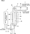
Fig. 1 illustrates the schematic configuration of an electrolyzedwater generation device 1 of this embodiment, In this embodiment, a home electrolyzed water generation device to be used for the generation of domestic drinking water is illustrated as the electrolyzedwater generation device 1, for example.Fig. 1 illustrates the electrolyzedwater generation device 1 in a state of generating electrolyzed hydrogen water for drinking. - The electrolyzed
water generation device 1 is provided with awater purification cartridge 2 purifying water and anelectrolytic cell 4 in which anelectrolytic chamber 40 to which the purified water is supplied is formed. - The
water purification cartridge 2 filters raw water supplied to the electrolyzedwater generation device 1 to thereby generate purified water, and then supplies the same to theelectrolytic chamber 40. For the raw water, tap water is generally used and, besides the tap water, well water, and groundwater are usable, for example. Thewater purification cartridge 2 is configured so as to be detachable and attachable to the device body of the electrolyzedwater generation device 1. Thus, thewater purification cartridge 2 which has reached the end of the service life due to use or the lapse of time can be exchanged for a newwater purification cartridge 2. - The
water purification cartridge 2 is provided on the upstream side of theelectrolytic cell 4. Therefore, water purified by thewater purification cartridge 2 is supplied to theelectrolytic cell 4. - The water purified by the
water purification cartridge 2 is electrolyzed in theelectrolytic chamber 40. In theelectrolytic chamber 40, there are provided afirst power feeder 41 and asecond power feeder 42 disposed facing each other and amembrane 43 arranged between thefirst power feeder 41 and thesecond power feeder 42. - The
membrane 43 divides theelectrolytic chamber 40 into a firstpolar chamber 40a on the side of thefirst power feeder 41 and a secondpolar chamber 40b on the side of thesecond power feeder 42. Themembrane 43 allows ions produced in electrolysis to pass. Thefirst power feeder 41 and thesecond power feeder 42 are electrically connected to each other through themembrane 43. when a direct-current voltage is applied between thefirst power feeder 41 and thesecond power feeder 42, water is electrolyzed in theelectrolytic chamber 40, so that electrolyzed water is obtained. - For example, in the state illustrated in
Fig. 1 , thefirst power feeder 41 is positively charged and the firstpolar chamber 40a functions as an anode chamber. Meanwhile, thesecond power feeder 42 is negatively charged and the secondpolar chamber 40b functions as a cathode chamber. More specifically, a reductive electrolyzed hydrogen water in which the generated hydrogen gas is melted is generated in the secondpolar chamber 40b and electrolyzed acid water in which the generated oxygen gas is melted is generated in the firstpolar chamber 40a. -
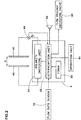
Fig. 2 illustrates the electric configuration of the electrolyzedwater generation device 1. The electrolyzedwater generation device 1 is provided with acontrol unit 5 managing the control of each portion ofelectrolytic cell 4 and the like, for example. - The
first power feeder 41, thesecond power feeder 42, and thecontrol unit 5 are connected through a current supply line. On the current supply line between thefirst power feeder 41 and thecontrol unit 5, acurrent detection unit 44 is provided. Thecurrent detection unit 44 may be provided on the current supply line between thesecond power feeder 42 and thecontrol unit 5. Thecurrent detection unit 44 always or periodically detects a direct current (electrolytic current) I to be supplied to thefirst power feeder 41 and thesecond power feeder 42 and outputs an electric signal equivalent to the value to thecontrol unit 5. - The
control unit 5 controls a direct-current voltage (electrolytic voltage) v to be applied to thefirst power feeder 41 and thesecond power feeder 42 based on the electric signal output from thecurrent detection unit 44, for example. More specifically, thecontrol unit 5 feedback-controls a voltage v to be applied to thefirst power feeder 41 and thesecond power feeder 42 so that the current I detected by thecurrent detection unit 44 is a desired value according to the dissolved hydrogen concentration set by a user, for example. For example, thecontrol unit 5 reduces the voltage V when the current I is excessively large and thecontrol unit 5 increases the voltage V when the current I is excessively small. Thus, the current I to be supplied to thefirst power feeder 41 and thesecond power feeder 42 is appropriately controlled, so that hydrogen water of a desired dissolved hydrogen concentration is generated in theelectrolytic chamber 40. - The polarities of the
first power feeder 41 and thesecond power feeder 42 are controlled by thecontrol unit 5. More specifically, thecontrol unit 5 functions as apolarity switching unit 51 switching the polarities of thefirst power feeder 41 and thesecond power feeder 42. Due to the fact that thecontrol unit 5 switches the polarities of thefirst power feeder 41 and thesecond power feeder 42 as appropriate, the opportunities for thefirst power feeder 41 and thesecond power feeder 42 to function as a anode or a cathode are equalized. Then, the power feeder functioning as the cathode before the switching of the polarity functions as the anode after the switching of the polarity and cleans scale deposited before the switching. Thus, the adhesion of scale to thefirst power feeder 41 and thesecond power feeder 42 is suppressed. - The
control unit 5 has a CPU (Central Processing Unit) performing various kinds of operation processing and information processing, programs controlling the operation of the CPU and a memory storing various kinds of information, for example. Various kinds of functions of thecontrol unit 5 are realized by the CPU, the memory, and the programs. - The electrolyzed
water generation device 1 operates in various kinds of operation modes under the control by thecontrol unit 5. The operation modes of the electrolyzedwater generation device 1 include a "hydrogen water mode" of generating and discharging electrolyzed hydrogen water, an "acid water mode" of generating and discharging electrolyzed acid water, and a "purified water mode" of generating and discharging purified water. - The electrolyzed
water generation device 1 has anoperation unit 61 to be operated by a user. Theoperation unit 61 is operated by a user when changing the operation modes of the electrolyzedwater generation device 1, for example. - The
operation unit 61 has a switch corresponding to each mode, a touch panel detecting the electrostatic capacity, or the like. A user can select water to be generated by the electrolyzedwater generation device 1 by operating theoperation unit 61. A user can set the dissolved hydrogen concentration of electrolyzed hydrogen water to be generated by the electrolyzedwater generation device 1 by operating theoperation unit 61. when theoperation unit 61 is operated by a user, theoperation unit 61 outputs a corresponding electric signal to thecontrol unit 5. - As illustrated in
Fig. 1 , the electrolyzedwater generation device 1 is further provided with awater inlet portion 7 provided on the upstream side of theelectrolytic cell 4 and awater outlet portion 8 provided on the downstream side of theelectrolytic cell 4. - The
water inlet portion 7 has awater supply pipe 71, aflow rate sensor 72, a branchingportion 73, a flow rate regulating valve 74, and the like. Thewater supply pipe 71 supplies water purified by thewater purification cartridge 2 to theelectrolytic chamber 40. Theflow rate sensor 72 is provided on thewater supply pipe 71. Theflow rate sensor 72 periodically detects a flow rate F1 per unit time of water to be supplied to the electrolytic chamber 40 (hereinafter also simply referred to as "flow rate"), and then outputs a signal equivalent to the value to thecontrol unit 5. - The branching
portion 73 branches thewater supply pipe 71 into two parts ofwater supply pipes water supply pipe polar chamber 40a or the secondpolar chamber 40b. The flow rate of water to be supplied to the firstpolar chamber 40a and the secondpolar chamber 40b is regulated by the flow rate regulating valve 74 under the management of thecontrol unit 5. In this embodiment, theflow rate sensor 72 is provided on the upstream side of the branchingportion 73, and therefore detects the total flow rate of the flow rate of water to be supplied to the firstpolar chamber 40a and the flow rate of water to be supplied to the secondpolar chamber 40b, i.e., first flow rate F1 of water to be supplied to theelectrolytic chamber 40. - The
water outlet portion 8 has a flowpassage switching valve 85, afirst flow passage 81, asecond flow passage 82, and the like. The flowpassage switching valve 85 switches the connections between the firstpolar chamber 40a and the secondpolar chamber 40b and thefirst flow passage 81 and thesecond flow passage 82. - In a tip portion of the
first flow passage 81, a firstwater discharge port 83 is provided. Thefirst flow passage 81 delivers electrolyzed water generated in one of the firstpolar chamber 40a and the secondpolar chamber 40b to the firstwater discharge port 83. Similarly, a secondwater discharge port 84 is provided in a tip portion of thesecond flow passage 82. Thesecond flow passage 82 delivers electrolyzed water generated in the other one of the firstpolar chamber 40a and the secondpolar chamber 40b to the secondwater discharge port 84. - By synchronizing the switching of the polarities of the
first power feeder 41 and thesecond power feeder 42 and the switching of the flow passage by the flowpassage switching valve 85, electrolyzed water (electrolyzed hydrogen water inFig. 1 ) selected by a user can be always discharged from one water discharge port (for example, first water discharge port 83). - In the switching of the polarities of the
first power feeder 41 and thesecond power feeder 42, an aspect is desirable in which thecontrol unit 5 interlockingly operates the flow rate regulating valve 74 and the flowpassage switching valve 85. Thus, effective use of water is enabled while sufficiently securing the supply amount of water to the polar chamber connected to the firstwater discharge port 83 before and after the switching of the polarity and suppressing the supply amount of the water to the polar chamber connected to the secondwater discharge port 84. An aspect is desirable in which the flow rate regulating valve 74 and the flowpassage switching valve 85 are integrally formed and are interlockingly driven by a single motor as described in Japanese Patent No.5809208 passage switching valve 85 are configured by an outer cylindrical body and an inner cylindrical body having a cylindrical shape or the like. In the inside and the outside of the inner cylindrical body, flow passages configuring the flow rate regulating valve 74 and the flowpassage switching valve 85 are formed. The flow passages are configured so as to cross as appropriate according to the operating states of the flow rate regulating valve 74 and the flowpassage switching valve 85. Such a valve device is referred to as "double autochange crossline valve" and contributes to the simplification of the configuration and the control of the electrolyzedwater generation device 1 and further increases the commercial value of the electrolyzedwater generation device 1. - As already described above, the electrolyzed
water generation device 1 of the present invention is configured so as to switch the polarities of thefirst power feeder 41 and thesecond power feeder 42 as appropriate in order to suppress the adhesion of scale to the surfaces of thefirst power feeder 41 and thesecond power feeder 42. The switching timing of the polarities of thefirst power feeder 41 and thesecond power feeder 42 is managed by thecontrol unit 5. Moreover, thecontrol unit 5 controls the flowpassage switching valve 85 to switch the connections between the firstpolar chamber 40a and the secondpolar chamber 40b and thefirst flow passage 81 and thesecond flow passage 82 synchronizing with the switching of the polarities of thefirst power feeder 41 and thesecond power feeder 42. More specifically, thecontrol unit 5 functions as adetermination unit 52 determining the switching timing of the polarities of thefirst power feeder 41 and thesecond power feeder 42 and the flowpassage switching valve 85. - As illustrated in
Fig. 2 , the electrolyzedwater generation device 1 is provided with aspeaker 62 for outputting various kinds of sounds guiding a user's operation. Thespeaker 62 is controlled by thecontrol unit 5. - In electrolyzed water discharged from the first
water discharge port 83 or the like immediately after starting water supply, desired pH and dissolved gas concentration are hard to be obtained. Therefore, this electrolyzedwater generation device 1 is configured so as to sound a melody from thespeaker 62 after the lapse of a T1 second in which it is presumed that the pH and the dissolved gas concentration of electrolyzed water to be discharged from firstwater discharge port 83 are stabilized and desired electrolyzed water is obtained. The T1 is set to about several seconds, for example, according to the specification of theelectrolytic chamber 40 and the length of thefirst flow passage 81. - In the first
polar chamber 40a, the secondpolar chamber 40b, and the flowpassage switching valve 85 immediately after switching the polarities of thefirst power feeder 41 and thesecond power feeder 42 and the flowpassage switching valve 85, electrolyzed water generated with a different polarity remains. Therefore, in electrolyzed water generated immediately after switching the polarity of thesecond power feeder 42 and the flowpassage switching valve 85, the electrolyzed water generated with a different polarity is mixed. Then, this electrolyzedwater generation device 1 is configured so as to sound a melody from thespeaker 62 after the lapse of a T2 (larger than T1) second in which it is presumed that the electrolyzed water generated with a different polarity is discharged from the firstwater discharge port 83. The T2 is set to about twice the T1, for example, according to the specification of the flowpassage switching valve 85 and the length of thefirst flow passage 81. - The time, such as the T1 second and the T2 second, is counted by the
control unit 5. More specifically, thecontrol unit 5 has a function as atimer 53 counting the time based on a clock signal or the like. In the electrolyzedwater generation device 1 of this embodiment, the time, such as the T1 second or the T2 second, is set as waiting time until desired electrolyzed water is discharged after starting water supply. By the melody sounded after the lapse of the T1 second and the T2, a user can recognize that electrolyzed water selected by operating theoperation unit 61 is generated, and thus the usability of the electrolyzedwater generation device 1 is increased. -
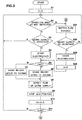
Figs. 3 and4 are flow charts illustrating the switching operations of the polarities of thefirst power feeder 41 and thesecond power feeder 42 and the flowpassage switching valve 85 in the electrolyzedwater generation device 1. For the determination of the switching timing of the polarities of thepower feeders passage switching valve 85, a variable n equivalent to the number of times of the electrolysis after switching the polarity is used. - First, in S1, the
control unit 5 resets the variable n to 0 which is an initial value. Thereafter, when the water supply is detected through the flow rate sensor 72 (Y in S3) without the operation mode being switched by a user (Y in S2), thecontrol unit 5 applies the direct-current voltage V to thefirst power feeder 41 and thesecond power feeder 42 to start electrolysis (S4). The detection of the water supply and the stop of the water supply are determined based on a signal to be input into thecontrol unit 5 from theflow rate sensor 72. More specifically, theflow rate sensor 72 and thecontrol unit 5 function as water supply detection units. Thecontrol unit 5 determines that the state is in the water supply state when the flow rate in theflow rate sensor 72 exceeds the predetermined threshold value and determines that the state is in the water supply stopped state when the flow rate in theflow rate sensor 72 is less than the threshold value. - Then, when the variable n is 0 (Y in S5), the
control unit 5 determines that electrolysis immediately after switching the polarities of thefirst power feeder 41 and thesecond power feeder 42 and the flowpassage switching valve 85 is performed, and then causes thespeaker 62 to output a melody after the lapse of the T2 seconds (S6). On the other hand, when the variable n is not 0 (N in S5), thecontrol unit 5 causes thespeaker 62 to output a melody after the lapse of the T1 second (S7). - Thereafter, when the stop of the water supply is detected through the flow rate sensor 72 (S8), the
control unit 5 stops the electrolysis (S9) by stopping the application of the direct-current voltage V to thefirst power feeder 41 and thesecond power feeder 42, and then increments the variable n by 1 (S10). In the subsequent S11, it is determined whether the variable n reaches a predetermined number N (N is an integer of 2 or more). when the variable n does not reach the number N (N in S11), the process returns to S2, and then the loop to S11 is repeated, In this case, the switching of the polarity is not performed. - On the other hand, when the variable n reaches the number N (Y in S11), the
control unit 5 counts the time after stopping the electrolysis (S12). Then, when a predetermined time δT passes (Y in S15) without the switching of the operation modes and the water supply being detected (Y in S13, N in S14), thecontrol unit 5 determines that the switching timing of the polarities of thepower feeders passage switching valve 85 arrives, and then switches the polarities of thepower feeders - Each processing of S1 to S16 is performed while always being looped in the operation of the electrolyzed
water generation device 1. More specifically, after the processing of S16 is completed, the processing of S1 is performed. More specifically, thecontrol unit 5 switches the polarities of thepower feeders passage switching valve 85 in S16 to prepare for the detection (S3) of water supply by theflow rate sensor 72 of the next loop. Thus, the power feeder functioning as a cathode to generate electrolyzed hydrogen water in the last loop functions as an anode to clean a deposited scale. Therefore, due to the repetition of such a loop, the electrolyzed hydrogen water generation step and the scale cleaning step are alternately repeated, so that the adhesion of scale to the surfaces of thefirst power feeder 41 and thesecond power feeder 42 is continuously suppressed. - when the operation modes are switched by a user in S2 and S13 above (N in S2, N is S13), the process shifts to S21, and the
control unit 5 switches the flowpassage switching valve 85. Then, when the water supply is detected through the flow rate sensor 72 (Y in S22), the direct-current voltage V is applied to thefirst power feeder 41 and thesecond power feeder 42 to start electrolysis (S23). Thereafter, thecontrol unit 5 resets the variable n to 0, and then shifts to S5. Moreover, when the operation mode is switched to the purified water mode in S2 (N in S2), purified water generated by thewater purification cartridge 2 may be supplied through the firstpolar chamber 40a or the secondpolar chamber 40b without being electrolyzed, and therefore S21 and S23 are skipped. - Furthermore, when the water supply is detected by the flow rate sensor 72 (Y in S14) in S14 above, the
control unit 5 applies the direct-current voltage V to thefirst power feeder 41 and thesecond power feeder 42 to start electrolysis (S31), and then causes thespeaker 62 to output a melody after the lapse of the T1 second (S32). Thereafter, when the stop of the water supply is detected through the flow rate sensor 72 (S33), thecontrol unit 5 stops the application of the direct-current voltage V to thefirst power feeder 41 and thesecond power feeder 42 to thereby stop the electrolysis (S34), resets the counted time (S35), and then returns to S12. In this case, the switching of the polarity is not performed. - As illustrated in S2 to S11 of
Fig. 3 , in this electrolyzedwater generation device 1, thecontrol unit 5 determines the switching timing on the assumption that electrolysis is performed by the predetermined number of times N or more in theelectrolytic chamber 40 without the polarities of thepower feeders first power feeder 41 and thesecond power feeder 42 can be suppressed. - Furthermore, in this electrolyzed
water generation device 1, thecontrol unit 5 determines that the switching timing arrives when the predetermined time δT passes without detecting the water supply to the electrolytic chamber after the electrolysis is performed by the number of times N or more as illustrated in S12 to S15 ofFig. 4 . Therefore, when water is supplied to theelectrolytic chamber 40 several times for a short period of time during cooking, for example (Y in S14), the switching of the polarity is not performed during that time. In connection therewith, the waiting time until desired electrolyzed water is discharged without shifting to each processing from S1 to S6 in the next loop is maintained at the T1 second (S32). Therefore, the occurrence frequency of the situation in which the waiting time is prolonged from the T1 second to the T2 second in connection with the switching of the polarity decreases, so that the usability of the electrolyzedwater generation device 1 is further increased. - The flow
passage switching valve 85 is driven by a motor, for example. The switching of such a flowpassage switching valve 85 is accompanied by the operation sound of the motor. This embodiment can be configured so that the flowpassage switching valve 85 is switched during the time in which it can be presumed that a user moves to a place distant from the electrolyzedwater generation device 1 by defining the time δT as appropriate (for example, about several minutes to about ten and several minutes). Thus, a user is prevented from being bothered with the operation sound of the motor. - The electrolyzed
water generation device 1 of the present invention may be configured so that thecontrol unit 5 determines the switching timing based on the integrated time of electrolysis in addition to the number of times of electrolysis after the switching of the polarity and the time after stopping electrolysis described above (AND conditions), In this case, thecontrol unit 5 integrates the electrolysis time in theelectrolytic chamber 40. Thecontrol unit 5 determines that the switching timing arrives when the integrated electrolysis time reaches the predetermined threshold value without the polarities of thefirst power feeder 41 and thesecond power feeder 42 being switched. When the operation mode is switched and the polarity is switched before thecontrol unit 5 determines the arrival of the switching timing, the integrated value of the electrolysis time is reset to 0. According to the configuration in which the switching timing of the polarity is determined considering the integrated time of electrolysis, the frequency of switching the polarity can be reduced with higher accuracy while suppressing the adhesion of scale, so that the usability of the electrolyzedwater generation device 1 can be increased and discarded water can be reduced. - It may be configured so that the determination of the switching timing based on the integrated time of electrolysis is operated by the determination based on the number of times of electrolysis after the switching of the polarity and the time after stopping electrolysis and OR conditions, In this case, the adhesion of scale can be much more effectively suppressed.
- The current I to be supplied to the
first power feeder 41 and thesecond power feeder 42 is dependent on the flow rate per unit time detected by theflow rate sensor 72. Moreover, the current I is dependent on the dissolved hydrogen concentration set by a user. More specifically, thecontrol unit 5 controls the voltage v to be applied to thefirst power feeder 41 and thesecond power feeder 42 so that the current I becomes larger with an increase in the flow rate per unit time of water to be supplied to theelectrolytic cell 4. Moreover, thecontrol unit 5 controls the voltage v to be applied to thefirst power feeder 41 and thesecond power feeder 42 so that the current I becomes larger when the dissolved hydrogen concentration is set to be higher, In general, the deposited amount of scale is proportional to the time in which the current I and the electrolysis are performed. - Then, this embodiment may be configured so that the
control unit 5 changes the number of times N serving as the threshold value and the time δT based on the integrated value of the currents I (time integrated value of the currents I) to be supplied to thepower feeders power feeders passage switching valve 85. Thecontrol unit 5 calculates the integrated value of the currents I based on an electric signal output from thecurrent detection unit 44. - Then, when the integrated value of the currents I after switching the polarities of the
power feeders passage switching valve 85 is smaller than the predetermined threshold value, for example, it can be presumed that the deposited amount of scale is relatively small to the number of times of electrolysis. Therefore, by setting the number of times N serving as the threshold value to be large or setting the time δT to be large, the frequency of switching the polarity can be reduced, so that the usability of the electrolyzedwater generation device 1 can be increased. On the other hand, when the integrated value of the currents I after switching the polarities of thepower feeders passage switching valve 85 is larger than the predetermined threshold value, it can be presumed that the deposited amount of scale is relatively large to the number of times of electrolysis. Therefore, the frequency of switching the polarity can be reduced by setting the number of times N serving as the threshold value to be small or setting the time δT to be small. Therefore, by changing the number of times N and the time δT based on the integrated value of the currents I after switching the polarities of thepower feeders passage switching valve 85, the switching timing can be much more accurately managed. - The deposited amount of scale is dependent on the components of water to be supplied to the
electrolytic chamber 40. when water containing a large amount of mineral components, such as calcium, is supplied to theelectrolytic chamber 40, the deposited amount of scale tends to increase. The water containing a large amount of the mineral components has a small resistance value, and therefore the current I corresponding to the flow rate and a desired dissolved hydrogen water concentration is obtained at a relatively low voltage V. - Then, this embodiment may be configured so that the
control unit 5 changes the number of times N serving as the threshold value and the time δT based on the ratio V/I of the voltage v to be applied to thepower feeders power feeders passage switching valve 85. In this case, thecontrol unit 5 functions as a voltage detection unit always or periodically detecting the voltage V to be feedback-controlled. The ratio V/I is calculated by thecontrol unit 5 based on an electric signal output from thecurrent detection unit 44 and the voltage v. For example, thecontrol unit 5 calculates the ratio V/I by periodically detecting the voltage V to be applied to thepower feeders control unit 5 can automatically adjust the frequency of switching the polarity and the flowpassage switching valve 85 according to the water quality of an area where the electrolyzedwater generation device 1 is to be used. - More specifically, when the average value of the ratio V/I after switching the polarities of the
power feeders passage switching valve 85 is smaller than the predetermined threshold value, it can be presumed that the deposited amount of scale is relatively large to the number of times of electrolysis. Therefore, by setting the number of times N serving as the threshold value to be small and the time δT to be small, the frequency of switching the polarity can be increased to suppress the adhesion of scale. On the other hand, when the average value of the ratio V/I after switching the polarities of thepower feeders passage switching valve 85 is larger than the predetermined threshold value, it can be presumed that the deposited amount of scale is relatively small to the number of times of electrolysis. Therefore, by setting the number of times N serving as the threshold value to be large and setting the time δT to be large, the frequency of switching the polarity can be reduced and the usability of the electrolyzedwater generation device 1 can be increased. - As described above, the electrolyzed
water generation device 1 of the present invention is described in detail but the present invention is altered to various aspects to be implemented without being limited to the specific embodiment described above. More specifically, the electrolyzed water generation device 1 may be configured so as to be provided with at least the electrolytic chamber 40 to which water to be electrolyzed is supplied, the first power feeder 41 and the second power feeder 42 disposed facing each other in the electrolytic chamber 40, and the membrane 43 arranged between the first power feeder 41 and the second power feeder 42 and dividing the electrolytic chamber 40 into the first polar chamber 40a on the side of the first power feeder 41 and the second polar chamber 40b on the side of the second power feeder 42 and to be further provided with the first flow passage 81 delivering electrolyzed water generated in one of the first polar chamber 40a and the second polar chamber 40b to the first water discharge port 83, the second flow passage 82 delivering electrolyzed water generated in the other one of the first polar chamber 40a and the second polar chamber 40b to the second water discharge port 84, the flow passage switching valve 85 switching the connections between the first polar chamber 40a and the second polar chamber 40b and the first flow passage 81 and the second flow passage 82, the polarity switching unit 51 switching the polarities of the first power feeder 41 and the second power feeder 42, the determination unit 52 determining the switching timing of the polarity switching unit 51 and the flow passage switching valve 85, and the flow rate sensor 72 detecting the water supply to the electrolytic chamber 40 and configured so that the determination unit 52 determines that the switching timing arrives when the predetermined time passes without the flow rate sensor 72 detecting the water supply to the electrolytic chamber 40 after electrolysis is performed by the predetermined number of times or more in the electrolytic chamber 40 without the polarity being switched. -
- 1
- electrolyzed water generation device
- 5
- control unit
- 40
- electrolytic chamber
- 40a
- first polar chamber
- 40b
- second polar chamber
- 41
- first power feeder
- 42
- second power feeder
- 43
- membrane
- 44
- current detection unit
- 51
- polarity switching unit
- 52
- determination unit
- 72
- flow rate sensor (water supply detection unit)
- 81
- first flow passage
- 82
- second flow passage
- 83
- first water discharge port
- 84
- second water discharge port
- 85
- flow passage switching valve
Claims (6)
- An electrolyzed water generation device comprising:an electrolytic chamber to which water to be electrolyzed is supplied;a first power feeder and a second power feeder disposed facing each other in the electrolytic chamber; anda membrane arranged between the first power feeder and the second power feeder and dividing the electrolytic chamber into a first polar chamber on a side of the first power feeder and a second polar chamber on a side of the second power feeder, characterized in thatthe electrolyzed water generation device further comprises:a first flow passage delivering electrolyzed water generated in one of the first polar chamber and the second polar chamber to a first water discharge port;a second flow passage delivering electrolyzed water generated in another one of the first polar chamber and the second polar chamber to a second water discharge port;a flow passage switching valve switching connections of the first polar chamber and the second polar chamber to the first flow passage and the second flow passage;a polarity switching unit switching polarities of the first power feeder and the second power feeder;a determination unit determining switching timing of the polarity switching unit and the flow passage switching valve; anda water supply detection unit detecting water supply to the electrolytic chamber, and whereinthe determination unit determines that the switching timing arrives when a predetermined time passes without the water supply detection unit detecting water supply to the electrolytic chamber after electrolysis is performed by a predetermined number of times or more in the electrolytic chamber without the polarities being switched.
- The electrolyzed water generation device according to Claim 1, wherein
the determination unit
integrates electrolysis time in the electrolytic chamber and
determines that the switching timing arrives when said time passes after the electrolysis is performed by said number of times or more in the electrolytic chamber without the polarities being switched and the integrated electrolysis time reaches a predetermined threshold value. - The electrolyzed water generation device according to Claim 1 or 2 further comprising:a current detection unit detecting a current to be supplied to the first power feeder and the second power feeder, whereinthe determination unit changes said number of times based on said integrated value of the currents after switching the polarity and the flow passage.
- The electrolyzed water generation device according to Claim 3, wherein
the determination unit changes said time based on said integrated value of the currents after switching the polarity and the flow passage. - The electrolyzed water generation device according to Claim 3 or 4 further comprising:a voltage detection unit detecting a voltage to be applied to the first power feeder and the second power feeder, whereinthe determination unit changes said number of times based on a ratio of the voltage to the current after switching the polarity and the flow passage.
- The electrolyzed water generation device according to Claim 5, wherein
the determination unit changes said time based on the ratio of the voltage to the current.
Applications Claiming Priority (2)
| Application Number | Priority Date | Filing Date | Title |
|---|---|---|---|
| JP2016143627A JP6209254B1 (en) | 2016-07-21 | 2016-07-21 | Electrolyzed water generator |
| PCT/JP2017/026256 WO2018016575A1 (en) | 2016-07-21 | 2017-07-20 | Electrolyzed water generation device |
Publications (3)
| Publication Number | Publication Date |
|---|---|
| EP3486221A1 EP3486221A1 (en) | 2019-05-22 |
| EP3486221A4 EP3486221A4 (en) | 2020-02-19 |
| EP3486221B1 true EP3486221B1 (en) | 2020-12-09 |
Family
ID=59997799
Family Applications (1)
| Application Number | Title | Priority Date | Filing Date |
|---|---|---|---|
| EP17831091.8A Active EP3486221B1 (en) | 2016-07-21 | 2017-07-20 | Electrolyzed water generation device |
Country Status (7)
| Country | Link |
|---|---|
| US (1) | US11124435B2 (en) |
| EP (1) | EP3486221B1 (en) |
| JP (1) | JP6209254B1 (en) |
| KR (1) | KR102636761B1 (en) |
| CN (1) | CN109153586B (en) |
| TW (1) | TWI727073B (en) |
| WO (1) | WO2018016575A1 (en) |
Families Citing this family (2)
| Publication number | Priority date | Publication date | Assignee | Title |
|---|---|---|---|---|
| JP7037381B2 (en) * | 2018-02-09 | 2022-03-16 | 株式会社日本トリム | Electrolyzed water supply device |
| JP6988564B2 (en) * | 2018-02-26 | 2022-01-05 | Toto株式会社 | Electrolyzed water spouting device |
Family Cites Families (18)
| Publication number | Priority date | Publication date | Assignee | Title |
|---|---|---|---|---|
| JPS59189871U (en) * | 1983-06-03 | 1984-12-17 | 岡崎 龍夫 | water electrolyzer |
| US5234563A (en) | 1992-06-01 | 1993-08-10 | Janix Kabushiki Kaisha | Electrolytic ionized water producer of a continuous type |
| EP0612694B1 (en) * | 1993-02-22 | 1998-05-06 | Nippon Intek Co., Ltd. | Method and device for producing electrolytic water |
| JP3358234B2 (en) * | 1993-05-31 | 2002-12-16 | 松下電器産業株式会社 | Alkaline ion water purifier |
| AUPM498394A0 (en) * | 1994-04-12 | 1994-05-05 | Berrett Pty Ltd | Electrolytic water treatment |
| JPH091145A (en) * | 1995-06-16 | 1997-01-07 | Tokico Ltd | Electrolyzed water forming device |
| JPH0985244A (en) * | 1995-09-20 | 1997-03-31 | Tokico Ltd | Electrolytic water preparation device |
| JPH09155356A (en) * | 1995-12-05 | 1997-06-17 | Sanden Corp | Water supply apparatus |
| JP3766848B2 (en) * | 1995-12-25 | 2006-04-19 | 松下電工株式会社 | Electrolyzed water generator |
| CN1136153C (en) * | 1997-10-23 | 2004-01-28 | 星崎电机株式会社 | Electrolyzed water production apparatus |
| JP3443308B2 (en) | 1998-03-06 | 2003-09-02 | ホシザキ電機株式会社 | Electrolyzed water generator |
| JP2002273426A (en) | 2001-03-16 | 2002-09-24 | Zojirushi Corp | Ionic water generator |
| JP4874104B2 (en) * | 2004-07-15 | 2012-02-15 | 三浦電子株式会社 | Electrolyzed water generation / dilution supply equipment |
| JP5470088B2 (en) * | 2010-02-22 | 2014-04-16 | ホシザキ電機株式会社 | Electrolytic operation method of electrolyzed water generating apparatus equipped with diaphragm electrolyzer |
| JP2012125715A (en) * | 2010-12-16 | 2012-07-05 | Toto Ltd | Electrolytic apparatus, and hygienic cleaning apparatus |
| KR101893006B1 (en) * | 2011-10-14 | 2018-10-05 | 삼성전자주식회사 | Apparatus for reducing water by electrolysis and method for controlling the same |
| JP5809208B2 (en) * | 2013-07-31 | 2015-11-10 | 株式会社日本トリム | Electrolyzed water generator |
| JP5639724B1 (en) * | 2014-03-17 | 2014-12-10 | 株式会社日本トリム | ELECTROLYTIC WATER GENERATING DEVICE AND MANUFACTURING METHOD THEREOF |
-
2016
- 2016-07-21 JP JP2016143627A patent/JP6209254B1/en active Active
-
2017
- 2017-07-20 US US16/319,007 patent/US11124435B2/en active Active
- 2017-07-20 KR KR1020187037249A patent/KR102636761B1/en active IP Right Grant
- 2017-07-20 WO PCT/JP2017/026256 patent/WO2018016575A1/en unknown
- 2017-07-20 CN CN201780030913.XA patent/CN109153586B/en active Active
- 2017-07-20 EP EP17831091.8A patent/EP3486221B1/en active Active
- 2017-07-20 TW TW106124413A patent/TWI727073B/en active
Non-Patent Citations (1)
| Title |
|---|
| None * |
Also Published As
| Publication number | Publication date |
|---|---|
| CN109153586B (en) | 2021-10-08 |
| JP6209254B1 (en) | 2017-10-04 |
| WO2018016575A1 (en) | 2018-01-25 |
| KR102636761B1 (en) | 2024-02-14 |
| TWI727073B (en) | 2021-05-11 |
| CN109153586A (en) | 2019-01-04 |
| JP2018012075A (en) | 2018-01-25 |
| US11124435B2 (en) | 2021-09-21 |
| TW201803813A (en) | 2018-02-01 |
| US20190276341A1 (en) | 2019-09-12 |
| EP3486221A1 (en) | 2019-05-22 |
| KR20190030656A (en) | 2019-03-22 |
| EP3486221A4 (en) | 2020-02-19 |
Similar Documents
| Publication | Publication Date | Title |
|---|---|---|
| EP3486222B1 (en) | Electrolyzed water generation device | |
| US11168008B2 (en) | Electrolyzed water generation device | |
| EP3486221B1 (en) | Electrolyzed water generation device | |
| JP6126635B2 (en) | Electrolyzed water generator | |
| EP3578519A1 (en) | Electrolyzed water generating device and electrolyzed water generating method | |
| CN114162924A (en) | Control method and control device of water making equipment and water making equipment | |
| JP5102553B2 (en) | Electrolyzed water generator | |
| JP6836944B2 (en) | Electrolyzed water generator | |
| JP7165119B2 (en) | Electrolyzed water generation method and electrolyzed water generator | |
| JP5886894B2 (en) | Electrolyzed water generator | |
| JP6154837B2 (en) | Electrolyzed water generator |
Legal Events
| Date | Code | Title | Description |
|---|---|---|---|
| STAA | Information on the status of an ep patent application or granted ep patent |
Free format text: STATUS: THE INTERNATIONAL PUBLICATION HAS BEEN MADE |
|
| PUAI | Public reference made under article 153(3) epc to a published international application that has entered the european phase |
Free format text: ORIGINAL CODE: 0009012 |
|
| STAA | Information on the status of an ep patent application or granted ep patent |
Free format text: STATUS: REQUEST FOR EXAMINATION WAS MADE |
|
| 17P | Request for examination filed |
Effective date: 20190214 |
|
| AK | Designated contracting states |
Kind code of ref document: A1 Designated state(s): AL AT BE BG CH CY CZ DE DK EE ES FI FR GB GR HR HU IE IS IT LI LT LU LV MC MK MT NL NO PL PT RO RS SE SI SK SM TR |
|
| AX | Request for extension of the european patent |
Extension state: BA ME |
|
| DAV | Request for validation of the european patent (deleted) | ||
| DAX | Request for extension of the european patent (deleted) | ||
| REG | Reference to a national code |
Ref country code: DE Ref legal event code: R079 Ref document number: 602017029417 Country of ref document: DE Free format text: PREVIOUS MAIN CLASS: C02F0001460000 Ipc: C02F0001461000 |
|
| A4 | Supplementary search report drawn up and despatched |
Effective date: 20200122 |
|
| RIC1 | Information provided on ipc code assigned before grant |
Ipc: C02F 1/461 20060101AFI20200116BHEP |
|
| GRAP | Despatch of communication of intention to grant a patent |
Free format text: ORIGINAL CODE: EPIDOSNIGR1 |
|
| STAA | Information on the status of an ep patent application or granted ep patent |
Free format text: STATUS: GRANT OF PATENT IS INTENDED |
|
| INTG | Intention to grant announced |
Effective date: 20200818 |
|
| GRAS | Grant fee paid |
Free format text: ORIGINAL CODE: EPIDOSNIGR3 |
|
| GRAA | (expected) grant |
Free format text: ORIGINAL CODE: 0009210 |
|
| STAA | Information on the status of an ep patent application or granted ep patent |
Free format text: STATUS: THE PATENT HAS BEEN GRANTED |
|
| AK | Designated contracting states |
Kind code of ref document: B1 Designated state(s): AL AT BE BG CH CY CZ DE DK EE ES FI FR GB GR HR HU IE IS IT LI LT LU LV MC MK MT NL NO PL PT RO RS SE SI SK SM TR |
|
| REG | Reference to a national code |
Ref country code: GB Ref legal event code: FG4D |
|
| REG | Reference to a national code |
Ref country code: AT Ref legal event code: REF Ref document number: 1343264 Country of ref document: AT Kind code of ref document: T Effective date: 20201215 Ref country code: CH Ref legal event code: EP |
|
| REG | Reference to a national code |
Ref country code: DE Ref legal event code: R096 Ref document number: 602017029417 Country of ref document: DE |
|
| REG | Reference to a national code |
Ref country code: IE Ref legal event code: FG4D |
|
| PG25 | Lapsed in a contracting state [announced via postgrant information from national office to epo] |
Ref country code: NO Free format text: LAPSE BECAUSE OF FAILURE TO SUBMIT A TRANSLATION OF THE DESCRIPTION OR TO PAY THE FEE WITHIN THE PRESCRIBED TIME-LIMIT Effective date: 20210309 Ref country code: GR Free format text: LAPSE BECAUSE OF FAILURE TO SUBMIT A TRANSLATION OF THE DESCRIPTION OR TO PAY THE FEE WITHIN THE PRESCRIBED TIME-LIMIT Effective date: 20210310 Ref country code: RS Free format text: LAPSE BECAUSE OF FAILURE TO SUBMIT A TRANSLATION OF THE DESCRIPTION OR TO PAY THE FEE WITHIN THE PRESCRIBED TIME-LIMIT Effective date: 20201209 Ref country code: FI Free format text: LAPSE BECAUSE OF FAILURE TO SUBMIT A TRANSLATION OF THE DESCRIPTION OR TO PAY THE FEE WITHIN THE PRESCRIBED TIME-LIMIT Effective date: 20201209 |
|
| REG | Reference to a national code |
Ref country code: AT Ref legal event code: MK05 Ref document number: 1343264 Country of ref document: AT Kind code of ref document: T Effective date: 20201209 |
|
| PG25 | Lapsed in a contracting state [announced via postgrant information from national office to epo] |
Ref country code: SE Free format text: LAPSE BECAUSE OF FAILURE TO SUBMIT A TRANSLATION OF THE DESCRIPTION OR TO PAY THE FEE WITHIN THE PRESCRIBED TIME-LIMIT Effective date: 20201209 Ref country code: LV Free format text: LAPSE BECAUSE OF FAILURE TO SUBMIT A TRANSLATION OF THE DESCRIPTION OR TO PAY THE FEE WITHIN THE PRESCRIBED TIME-LIMIT Effective date: 20201209 Ref country code: BG Free format text: LAPSE BECAUSE OF FAILURE TO SUBMIT A TRANSLATION OF THE DESCRIPTION OR TO PAY THE FEE WITHIN THE PRESCRIBED TIME-LIMIT Effective date: 20210309 |
|
| REG | Reference to a national code |
Ref country code: NL Ref legal event code: MP Effective date: 20201209 |
|
| PG25 | Lapsed in a contracting state [announced via postgrant information from national office to epo] |
Ref country code: NL Free format text: LAPSE BECAUSE OF FAILURE TO SUBMIT A TRANSLATION OF THE DESCRIPTION OR TO PAY THE FEE WITHIN THE PRESCRIBED TIME-LIMIT Effective date: 20201209 Ref country code: HR Free format text: LAPSE BECAUSE OF FAILURE TO SUBMIT A TRANSLATION OF THE DESCRIPTION OR TO PAY THE FEE WITHIN THE PRESCRIBED TIME-LIMIT Effective date: 20201209 |
|
| REG | Reference to a national code |
Ref country code: LT Ref legal event code: MG9D |
|
| PG25 | Lapsed in a contracting state [announced via postgrant information from national office to epo] |
Ref country code: RO Free format text: LAPSE BECAUSE OF FAILURE TO SUBMIT A TRANSLATION OF THE DESCRIPTION OR TO PAY THE FEE WITHIN THE PRESCRIBED TIME-LIMIT Effective date: 20201209 Ref country code: SK Free format text: LAPSE BECAUSE OF FAILURE TO SUBMIT A TRANSLATION OF THE DESCRIPTION OR TO PAY THE FEE WITHIN THE PRESCRIBED TIME-LIMIT Effective date: 20201209 Ref country code: PT Free format text: LAPSE BECAUSE OF FAILURE TO SUBMIT A TRANSLATION OF THE DESCRIPTION OR TO PAY THE FEE WITHIN THE PRESCRIBED TIME-LIMIT Effective date: 20210409 Ref country code: SM Free format text: LAPSE BECAUSE OF FAILURE TO SUBMIT A TRANSLATION OF THE DESCRIPTION OR TO PAY THE FEE WITHIN THE PRESCRIBED TIME-LIMIT Effective date: 20201209 Ref country code: EE Free format text: LAPSE BECAUSE OF FAILURE TO SUBMIT A TRANSLATION OF THE DESCRIPTION OR TO PAY THE FEE WITHIN THE PRESCRIBED TIME-LIMIT Effective date: 20201209 Ref country code: CZ Free format text: LAPSE BECAUSE OF FAILURE TO SUBMIT A TRANSLATION OF THE DESCRIPTION OR TO PAY THE FEE WITHIN THE PRESCRIBED TIME-LIMIT Effective date: 20201209 Ref country code: LT Free format text: LAPSE BECAUSE OF FAILURE TO SUBMIT A TRANSLATION OF THE DESCRIPTION OR TO PAY THE FEE WITHIN THE PRESCRIBED TIME-LIMIT Effective date: 20201209 |
|
| PG25 | Lapsed in a contracting state [announced via postgrant information from national office to epo] |
Ref country code: AT Free format text: LAPSE BECAUSE OF FAILURE TO SUBMIT A TRANSLATION OF THE DESCRIPTION OR TO PAY THE FEE WITHIN THE PRESCRIBED TIME-LIMIT Effective date: 20201209 Ref country code: PL Free format text: LAPSE BECAUSE OF FAILURE TO SUBMIT A TRANSLATION OF THE DESCRIPTION OR TO PAY THE FEE WITHIN THE PRESCRIBED TIME-LIMIT Effective date: 20201209 |
|
| REG | Reference to a national code |
Ref country code: DE Ref legal event code: R097 Ref document number: 602017029417 Country of ref document: DE |
|
| PG25 | Lapsed in a contracting state [announced via postgrant information from national office to epo] |
Ref country code: IS Free format text: LAPSE BECAUSE OF FAILURE TO SUBMIT A TRANSLATION OF THE DESCRIPTION OR TO PAY THE FEE WITHIN THE PRESCRIBED TIME-LIMIT Effective date: 20210409 |
|
| PLBE | No opposition filed within time limit |
Free format text: ORIGINAL CODE: 0009261 |
|
| STAA | Information on the status of an ep patent application or granted ep patent |
Free format text: STATUS: NO OPPOSITION FILED WITHIN TIME LIMIT |
|
| PG25 | Lapsed in a contracting state [announced via postgrant information from national office to epo] |
Ref country code: IT Free format text: LAPSE BECAUSE OF FAILURE TO SUBMIT A TRANSLATION OF THE DESCRIPTION OR TO PAY THE FEE WITHIN THE PRESCRIBED TIME-LIMIT Effective date: 20201209 Ref country code: AL Free format text: LAPSE BECAUSE OF FAILURE TO SUBMIT A TRANSLATION OF THE DESCRIPTION OR TO PAY THE FEE WITHIN THE PRESCRIBED TIME-LIMIT Effective date: 20201209 |
|
| 26N | No opposition filed |
Effective date: 20210910 |
|
| PG25 | Lapsed in a contracting state [announced via postgrant information from national office to epo] |
Ref country code: DK Free format text: LAPSE BECAUSE OF FAILURE TO SUBMIT A TRANSLATION OF THE DESCRIPTION OR TO PAY THE FEE WITHIN THE PRESCRIBED TIME-LIMIT Effective date: 20201209 Ref country code: SI Free format text: LAPSE BECAUSE OF FAILURE TO SUBMIT A TRANSLATION OF THE DESCRIPTION OR TO PAY THE FEE WITHIN THE PRESCRIBED TIME-LIMIT Effective date: 20201209 |
|
| PG25 | Lapsed in a contracting state [announced via postgrant information from national office to epo] |
Ref country code: ES Free format text: LAPSE BECAUSE OF FAILURE TO SUBMIT A TRANSLATION OF THE DESCRIPTION OR TO PAY THE FEE WITHIN THE PRESCRIBED TIME-LIMIT Effective date: 20201209 |
|
| REG | Reference to a national code |
Ref country code: CH Ref legal event code: PL |
|
| PG25 | Lapsed in a contracting state [announced via postgrant information from national office to epo] |
Ref country code: MC Free format text: LAPSE BECAUSE OF FAILURE TO SUBMIT A TRANSLATION OF THE DESCRIPTION OR TO PAY THE FEE WITHIN THE PRESCRIBED TIME-LIMIT Effective date: 20201209 |
|
| REG | Reference to a national code |
Ref country code: BE Ref legal event code: MM Effective date: 20210731 |
|
| PG25 | Lapsed in a contracting state [announced via postgrant information from national office to epo] |
Ref country code: LI Free format text: LAPSE BECAUSE OF NON-PAYMENT OF DUE FEES Effective date: 20210731 Ref country code: CH Free format text: LAPSE BECAUSE OF NON-PAYMENT OF DUE FEES Effective date: 20210731 |
|
| PG25 | Lapsed in a contracting state [announced via postgrant information from national office to epo] |
Ref country code: IS Free format text: LAPSE BECAUSE OF FAILURE TO SUBMIT A TRANSLATION OF THE DESCRIPTION OR TO PAY THE FEE WITHIN THE PRESCRIBED TIME-LIMIT Effective date: 20210409 Ref country code: LU Free format text: LAPSE BECAUSE OF NON-PAYMENT OF DUE FEES Effective date: 20210720 |
|
| PG25 | Lapsed in a contracting state [announced via postgrant information from national office to epo] |
Ref country code: IE Free format text: LAPSE BECAUSE OF NON-PAYMENT OF DUE FEES Effective date: 20210720 Ref country code: BE Free format text: LAPSE BECAUSE OF NON-PAYMENT OF DUE FEES Effective date: 20210731 |
|
| PG25 | Lapsed in a contracting state [announced via postgrant information from national office to epo] |
Ref country code: CY Free format text: LAPSE BECAUSE OF FAILURE TO SUBMIT A TRANSLATION OF THE DESCRIPTION OR TO PAY THE FEE WITHIN THE PRESCRIBED TIME-LIMIT Effective date: 20201209 |
|
| PG25 | Lapsed in a contracting state [announced via postgrant information from national office to epo] |
Ref country code: HU Free format text: LAPSE BECAUSE OF FAILURE TO SUBMIT A TRANSLATION OF THE DESCRIPTION OR TO PAY THE FEE WITHIN THE PRESCRIBED TIME-LIMIT; INVALID AB INITIO Effective date: 20170720 |
|
| PGFP | Annual fee paid to national office [announced via postgrant information from national office to epo] |
Ref country code: GB Payment date: 20230721 Year of fee payment: 7 |
|
| PGFP | Annual fee paid to national office [announced via postgrant information from national office to epo] |
Ref country code: FR Payment date: 20230726 Year of fee payment: 7 |
|
| PGFP | Annual fee paid to national office [announced via postgrant information from national office to epo] |
Ref country code: DE Payment date: 20230927 Year of fee payment: 7 |
|
| PG25 | Lapsed in a contracting state [announced via postgrant information from national office to epo] |
Ref country code: MK Free format text: LAPSE BECAUSE OF FAILURE TO SUBMIT A TRANSLATION OF THE DESCRIPTION OR TO PAY THE FEE WITHIN THE PRESCRIBED TIME-LIMIT Effective date: 20201209 |