EP3486121A1 - Method for controlling sound inside vehicle and vehicle avn system - Google Patents
Method for controlling sound inside vehicle and vehicle avn system Download PDFInfo
- Publication number
- EP3486121A1 EP3486121A1 EP17827960.0A EP17827960A EP3486121A1 EP 3486121 A1 EP3486121 A1 EP 3486121A1 EP 17827960 A EP17827960 A EP 17827960A EP 3486121 A1 EP3486121 A1 EP 3486121A1
- Authority
- EP
- European Patent Office
- Prior art keywords
- sound source
- sound
- vehicle
- zone
- focusing
- Prior art date
- Legal status (The legal status is an assumption and is not a legal conclusion. Google has not performed a legal analysis and makes no representation as to the accuracy of the status listed.)
- Withdrawn
Links
Images




Classifications
-
- B—PERFORMING OPERATIONS; TRANSPORTING
- B60—VEHICLES IN GENERAL
- B60R—VEHICLES, VEHICLE FITTINGS, OR VEHICLE PARTS, NOT OTHERWISE PROVIDED FOR
- B60R16/00—Electric or fluid circuits specially adapted for vehicles and not otherwise provided for; Arrangement of elements of electric or fluid circuits specially adapted for vehicles and not otherwise provided for
- B60R16/02—Electric or fluid circuits specially adapted for vehicles and not otherwise provided for; Arrangement of elements of electric or fluid circuits specially adapted for vehicles and not otherwise provided for electric constitutive elements
- B60R16/037—Electric or fluid circuits specially adapted for vehicles and not otherwise provided for; Arrangement of elements of electric or fluid circuits specially adapted for vehicles and not otherwise provided for electric constitutive elements for occupant comfort, e.g. for automatic adjustment of appliances according to personal settings, e.g. seats, mirrors, steering wheel
-
- B—PERFORMING OPERATIONS; TRANSPORTING
- B60—VEHICLES IN GENERAL
- B60R—VEHICLES, VEHICLE FITTINGS, OR VEHICLE PARTS, NOT OTHERWISE PROVIDED FOR
- B60R16/00—Electric or fluid circuits specially adapted for vehicles and not otherwise provided for; Arrangement of elements of electric or fluid circuits specially adapted for vehicles and not otherwise provided for
- B60R16/02—Electric or fluid circuits specially adapted for vehicles and not otherwise provided for; Arrangement of elements of electric or fluid circuits specially adapted for vehicles and not otherwise provided for electric constitutive elements
-
- B—PERFORMING OPERATIONS; TRANSPORTING
- B60—VEHICLES IN GENERAL
- B60R—VEHICLES, VEHICLE FITTINGS, OR VEHICLE PARTS, NOT OTHERWISE PROVIDED FOR
- B60R16/00—Electric or fluid circuits specially adapted for vehicles and not otherwise provided for; Arrangement of elements of electric or fluid circuits specially adapted for vehicles and not otherwise provided for
- B60R16/02—Electric or fluid circuits specially adapted for vehicles and not otherwise provided for; Arrangement of elements of electric or fluid circuits specially adapted for vehicles and not otherwise provided for electric constitutive elements
- B60R16/03—Electric or fluid circuits specially adapted for vehicles and not otherwise provided for; Arrangement of elements of electric or fluid circuits specially adapted for vehicles and not otherwise provided for electric constitutive elements for supply of electrical power to vehicle subsystems or for
-
- B—PERFORMING OPERATIONS; TRANSPORTING
- B60—VEHICLES IN GENERAL
- B60R—VEHICLES, VEHICLE FITTINGS, OR VEHICLE PARTS, NOT OTHERWISE PROVIDED FOR
- B60R16/00—Electric or fluid circuits specially adapted for vehicles and not otherwise provided for; Arrangement of elements of electric or fluid circuits specially adapted for vehicles and not otherwise provided for
- B60R16/02—Electric or fluid circuits specially adapted for vehicles and not otherwise provided for; Arrangement of elements of electric or fluid circuits specially adapted for vehicles and not otherwise provided for electric constitutive elements
- B60R16/03—Electric or fluid circuits specially adapted for vehicles and not otherwise provided for; Arrangement of elements of electric or fluid circuits specially adapted for vehicles and not otherwise provided for electric constitutive elements for supply of electrical power to vehicle subsystems or for
- B60R16/0315—Electric or fluid circuits specially adapted for vehicles and not otherwise provided for; Arrangement of elements of electric or fluid circuits specially adapted for vehicles and not otherwise provided for electric constitutive elements for supply of electrical power to vehicle subsystems or for using multiplexing techniques
-
- G—PHYSICS
- G06—COMPUTING OR CALCULATING; COUNTING
- G06F—ELECTRIC DIGITAL DATA PROCESSING
- G06F3/00—Input arrangements for transferring data to be processed into a form capable of being handled by the computer; Output arrangements for transferring data from processing unit to output unit, e.g. interface arrangements
- G06F3/01—Input arrangements or combined input and output arrangements for interaction between user and computer
- G06F3/048—Interaction techniques based on graphical user interfaces [GUI]
- G06F3/0487—Interaction techniques based on graphical user interfaces [GUI] using specific features provided by the input device, e.g. functions controlled by the rotation of a mouse with dual sensing arrangements, or of the nature of the input device, e.g. tap gestures based on pressure sensed by a digitiser
- G06F3/0488—Interaction techniques based on graphical user interfaces [GUI] using specific features provided by the input device, e.g. functions controlled by the rotation of a mouse with dual sensing arrangements, or of the nature of the input device, e.g. tap gestures based on pressure sensed by a digitiser using a touch-screen or digitiser, e.g. input of commands through traced gestures
-
- H—ELECTRICITY
- H04—ELECTRIC COMMUNICATION TECHNIQUE
- H04R—LOUDSPEAKERS, MICROPHONES, GRAMOPHONE PICK-UPS OR LIKE ACOUSTIC ELECTROMECHANICAL TRANSDUCERS; ELECTRIC HEARING AIDS; PUBLIC ADDRESS SYSTEMS
- H04R5/00—Stereophonic arrangements
- H04R5/02—Spatial or constructional arrangements of loudspeakers
-
- H—ELECTRICITY
- H04—ELECTRIC COMMUNICATION TECHNIQUE
- H04R—LOUDSPEAKERS, MICROPHONES, GRAMOPHONE PICK-UPS OR LIKE ACOUSTIC ELECTROMECHANICAL TRANSDUCERS; ELECTRIC HEARING AIDS; PUBLIC ADDRESS SYSTEMS
- H04R5/00—Stereophonic arrangements
- H04R5/04—Circuit arrangements, e.g. for selective connection of amplifier inputs/outputs to loudspeakers, for loudspeaker detection, or for adaptation of settings to personal preferences or hearing impairments
-
- H—ELECTRICITY
- H04—ELECTRIC COMMUNICATION TECHNIQUE
- H04R—LOUDSPEAKERS, MICROPHONES, GRAMOPHONE PICK-UPS OR LIKE ACOUSTIC ELECTROMECHANICAL TRANSDUCERS; ELECTRIC HEARING AIDS; PUBLIC ADDRESS SYSTEMS
- H04R2499/00—Aspects covered by H04R or H04S not otherwise provided for in their subgroups
- H04R2499/10—General applications
- H04R2499/13—Acoustic transducers and sound field adaptation in vehicles
-
- H—ELECTRICITY
- H04—ELECTRIC COMMUNICATION TECHNIQUE
- H04S—STEREOPHONIC SYSTEMS
- H04S3/00—Systems employing more than two channels, e.g. quadraphonic
- H04S3/002—Non-adaptive circuits, e.g. manually adjustable or static, for enhancing the sound image or the spatial distribution
Definitions
- the present disclosure relates to an in-vehicle sound control method and a vehicle audio video navigation (AVN) system, and more particularly to an in-vehicle sound control method capable of individually setting a listening location of various sound sources which can be output in a vehicle and a vehicle audio video navigation (AVN) system.
- APN vehicle audio video navigation
- a sound control in the vehicle In addition to the development of an AVN system provided in a vehicle, more and more attentions are paid to a sound control in the vehicle.
- a sound of a portable device such as a mobile terminal, a PMP, an MP3 player, etc.
- a wireless and wired connection means such as Bluetooth, AUX, etc.
- active research is being conducted to control the sound output from the speaker in the vehicle in accordance with a location in the vehicle (a rider's position).
- a sound control technology includes, for example, a sound field reproduction method, an active noise control method which decreases a sound amount of a space by using a plurality of active sound sources, a method for changing an interval between the sound sources arranged in a specific shape, and a method for increasing a sound power which is radiated at a specific angle by changing a time delay between the sound sources and the magnitude of the sound input.
- US patent 5,802,190 (Title of the invention: Linear speaker array) discloses a technology for controlling indirect characteristics such as directionality by using a limited assumption which ignores the distance to the listener or reflection, etc.
- US patent 5,910,990 (Title of the invention: Apparatus and method for automatic equalization of personal multi-channel audio system) discloses a method for reproducing a signal without distortion by using transfer function.
- Korean Patent Application No. 10-2008-0125309 proposes a method for radiating a sound to a specific zone. However, it includes content that the sound is focused on the specific zone by disposing high directional speakers, etc.
- the above-mentioned documents have a problem in that it is difficult to control a zone on which the sound is intended to be focused in the environment, for example, a vehicle, where the locations of the speakers are fixed. That is, a hardware-based change is necessarily required because the sound cannot be focused on the specific zone by using existing mounted speakers.
- the conventional method for controlling the sound in a space by using a plurality of the sound sources simply changes the time delay between the sound sources and the magnitude of the sound input, and only changes the directionality of the sound source by using a restricted type of the sound source array, without considering a rider's position in the vehicle.
- the embodiment of the present invention is designed to overcome the above problems.
- the object of the present invention is to provide an in-vehicle sound control method capable of individually selecting, adjusting, and controlling a focusing zone of each sound output within a vehicle, and a vehicle audio video navigation (AVN) system.
- the object of the present invention is to provide the in-vehicle sound control method capable of easily selecting and controlling the focusing zone of the sound output within the vehicle by using existing mounted speakers without changing the location of the speaker within the vehicle, and the vehicle audio video navigation (AVN) system.
- a vehicle audio video navigation (AVN) system may be provided that includes: a plurality of source providers which receives a sound source; a user operation unit which selects at least one of a plurality of the sound sources input from the plurality of the source providers and selects a focusing zone of the sound source; a processor which generates a sound source signal for focusing an output of the selected sound source on the focusing zone; and a multi-channel amplifier which outputs the sound source signal.
- APN vehicle audio video navigation
- the multi-channel amplifier may simultaneously or selectively output the sound source signal generated for each of the plurality of the sound sources.
- An interior space of the vehicle may be divided into a plurality of the focusing zones.
- the vehicle AVN system may further include a storage which stores a filter coefficient corresponding to each of the plurality of the focusing zones.
- the processor may filter the selected sound source on the basis of the filter coefficient corresponding to the focusing zone selected by the user operation unit, and may generate the sound source signal.
- the user operation unit may be a touch screen which detects the user's selection of the sound source and the focusing zone on the basis of a touch signal applied by the user.
- the user operation unit may display a plurality of the focusing zones where the plurality of the sound sources and the output of the sound source are focused.
- the source provider may include a CD module, a radio module, a navigation module, an AUX module, a DVD module, a DMB module, a Bluetooth module, or a USB module.
- the processor may filter the sound source by using a filter coefficient which maximizes a ratio between a spatially averaged acoustic energy of the focusing zone selected by the user operation unit and a spatially averaged acoustic energy of a zone other than the selected focusing zone, and then may generate the sound source signal.
- the user operation unit may include a wireless communication module. At least one of the plurality of the sound sources input from the plurality of the source providers and a selection signal for the focusing zone of the sound source may be transmitted to the processor through the wireless communication module by the user operation unit.
- the user operation unit may be provided in at least one of seat zones provided in a vehicle.
- a vehicle audio video navigation (AVN) system including a vehicle AVN device and an external processor.
- the vehicle AVN device includes: a plurality of source providers which receives a sound source; a user operation unit which selects at least one of a plurality of the sound sources input from the plurality of the source providers and selects a focusing zone of the sound source; and a multi-channel amplifier.
- the external processor is connected to the vehicle AVN device, generates a sound source signal for focusing an output of the selected sound source on the focusing zone, and outputs the sound source signal through the multi-channel amplifier.
- the external processor may filter the selected sound source on the basis of the filter coefficient corresponding to the focusing zone selected by the user operation unit, and may generate the sound source signal.
- the external processor may filter the sound source by using a filter coefficient which maximizes a ratio between a spatially averaged acoustic energy of the focusing zone selected by the user operation unit and a spatially averaged acoustic energy of a zone other than the selected focusing zone, and then may generate the sound source signal.
- the user operation unit may include a wireless communication module. At least one of the plurality of the sound sources input from the plurality of the source providers and a selection signal for the focusing zone of the sound source may be transmitted to the external processor through the wireless communication module by the user operation unit.
- the user operation unit may be provided in at least one of seat zones provided in a vehicle.
- an in-vehicle sound control method including: receiving various sound sources through a plurality of source providers; detecting at least one of the plurality of the sound sources input through the plurality of the source providers and user's selection of a focusing zone of the sound source; generating a sound source signal for focusing an output of the selected sound source on the focusing zone; and outputting the generated sound source signal.
- the in-vehicle sound control method may further include displaying the plurality of the sound sources and a plurality of the focusing zones where the output of the sound source is focused.
- the outputting the generated sound source signal may output simultaneously or selectively the respective sound source signals corresponding to the plurality of the sound sources.
- the in-vehicle sound control method may further include storing a filter coefficient corresponding to each of the plurality of the focusing zones.
- the generating a sound source signal may filter the sound source on the basis of the filter coefficient corresponding to the focusing zone, and may generate the sound source signal.
- the filter coefficient may maximize a ratio between a spatially averaged acoustic energy of the focusing zone selected by the user operation unit and a spatially averaged acoustic energy of a zone other than the focusing zone.
- the in-vehicle sound control method it is possible to individually control the focusing zone of each sound output within the vehicle, and particularly to easily select and control the focusing zone of each sound without changing the location of the speaker within the vehicle. Further, according to the in-vehicle sound control method according to the embodiment of the present invention, the sound source and the focusing zone within the vehicle can be selected and controlled only by adding an external processor without replacing the AVN device provided in the vehicle.
- Fig. 1 is a view schematically showing a configuration for focusing zone setting.
- Fig. 1 schematically shows a means for transfer function measurement, such as an acoustic space, a speaker 110, a microphone 210, etc.
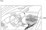
- a focusing zone setting system may be composed of a plurality of the speakers having independent channels and the microphone having 30 channels which are spaced apart from each other by an interval of 4 cm and are arranged in the form of 6x5 array.
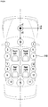
- the transfer function measurement may be performed in four seat zones, that is to say, a driver seat zone (front left, FL), a passenger seat zone (front right, FR), a rear left seat zone (RL), and a rear right seat zone (RR) shown in Fig. 2a in the vehicle.
- a driver seat zone front left, FL
- a passenger seat zone front right, FR
- a rear left seat zone RL
- a rear right seat zone RR
- the setting system can be implemented in various ways in accordance with the size, internal spatial structure, location of the internal configuration, etc., of the vehicle.
- a first speaker and a second speaker which function as a sound source, are installed in any location.
- the first speaker and the second speaker do not include a bright zone (hereinafter, referred to as BZ) and a dark zone (hereinafter, referred to as DZ).
- BZ bright zone
- DZ dark zone
- the bright zone (BZ) means a zone where a sound output from the first speaker and the second speaker is heard above a threshold value.
- the dark zone (DZ) means a zone where a sound output from the first speaker and the second speaker is heard below the threshold value.
- the bright zone (BZ) may be a zone where a sound can be heard and a zone where the sound source is focused by a user.
- the dark zone (DZ) may be a zone where a sound cannot be heard and a zone where the sound source is not focused by the user.
- the distinction between the bright zone (BZ) and the dark zone (DZ) is based on a contrast between sound pressure levels. Therefore, not only a sound may be controlled not to be heard in the dark zone (DZ), but also a small sound can be detected even in the dark zone (DZ).
- the bright zone (BZ) and the dark zone (DZ) are schematized and distinguished by a dotted circle.
- r s,i ; ⁇ ) (a signal which is sensed by the microphone) at any point r j generated by a first sound source and a second sound source can be represented by the following Equation 1.
- r j represents a j-th spatial point
- r s,i represents a location of an i-th sound source.
- Equation (1) may be represented with respect to two points in the form of a matrix by the following Equation (2).
- a first bright zone (BZ1), a second bright zone (BZ2), the dark zone (DZ), and a total sound zone (TZ) including the two foregoing zones are represented in the form of a matrix by the following Equations (3) to (5).
- the subscripts b, d, and t in Equations (3) to (5) represent the bright zone (BZ), the dark zone (DZ), and the total sound zone (TZ) respectively.
- a variable representative of the space is defined as a spatially averaged acoustic energy in the embodiment of the present invention.
- the variable representative of the space is defined as the spatially averaged acoustic energy because it is difficult to express acoustic characteristics within a zone only by the sound pressure levels themselves of the respective points.
- the spatially averaged acoustic potential energy of the bright zone (BZ), the spatially averaged acoustic energy of the dark zone (DZ), and the spatially averaged acoustic potential energy of the total sound zone (TZ) are sound pressure levels of each zone.
- Equation (6) the matrix is defined as a correlation matrix which indicates how much interference each sound source causes in a defined zone.
- the figure of 2 means the number of the microphones 210 in Equation (2) (see Fig. 1 ).
- the embodiment of the present invention takes a simple example. However, actually, the numeric means the number of the microphones included within a defined zone.
- the total magnitude of the input is defined as a sum of the absolute value of complex magnitude of the first sound source signal and the absolute value of complex magnitude of the second sound source signal. This can be referred to as a total magnitude of control effort.
- 2 is the total magnitude of the input, that is to say, a normalizing constant which changes the control effort into the dimension of the spatially averaged acoustic energy.
- Equation (11) The contrast between the sound pressure level and the total magnitude of the input in the bright zone (BZ) can be represented as the following Equation (11) by using the Equations (7) and (10). This is defined as "acoustic brightness".
- ⁇ q H R a q
- the determination of the sound source signal for maximizing the contrast between the sound pressure level and the total magnitude of the input in the bright zone (BZ) corresponds to how to obtain the sound source signal for maximizing the value of ⁇ in the Equation (11).
- Equation (11) can be formalized as a mathematical problem of maximizing Reyleigh quotient ⁇ . This is represented by the following Equation (12).
- R b q ⁇
- the obtaining of the sound source signal for maximizing the value of ⁇ is equal to the obtaining of a maximum eigenvalue of a generalized eigenvalue problem. Also, an eigenvector corresponding to the maximum eigenvalue becomes the first sound source signal and the second sound source signal.
- the input signal of the sound source for maximizing the contrast between the sound pressure level of the bright zone (BZ) and the sound pressure level of the dark zone (DZ) is considered.
- the sound pressure level of the bright zone (BZ) with respect to that of the dark zone (DZ) can be mathematically represented by the following Equation (13). This is defined as "acoustic contrast 1".
- ⁇ q H R b q q H R d q R d ⁇ 1
- R b q ⁇ ⁇ q
- Equation (13) can be formalized as a problem of maximizing Reyleigh quotient ⁇ .
- the obtaining of the sound source signal for maximizing the value of ⁇ is equal to the obtaining of a maximum eigenvalue of a generalized eigenvalue problem.
- an eigenvector corresponding to the maximum eigenvalue becomes the first sound source signal and the second sound source signal.
- the embodiment of the present invention uses a method for obtaining an optimized sound source control signal by analyzing all the transfer functions.
- the embodiment of the present invention is able to increase a relative difference of the sound pressure level in accordance with the zone. In other words, it is possible to perform control to increase the acoustic contrast between two different zones as well as the magnitude of the sound pressure level corresponding to the acoustic brightness.
- the sound source input signal for maximizing the contrast between the sound pressure level of the bright zone (BZ) and the sound pressure level of the total sound zone (TZ) will be described.
- the sound pressure level of the total sound zone (TZ) with respect to that of the dark zone (DZ) can be mathematically represented by the following Equation (15). This is defined as "acoustic contrast 2".
- Equation (15) can be formalized as a problem of maximizing Reyleigh quotient ⁇ '.
- the obtaining of the sound source signal for maximizing the value of ⁇ ' is equal to the obtaining of a maximum eigenvalue of a generalized eigenvalue problem.
- an eigenvector corresponding to the maximum eigenvalue becomes the first sound source signal and the second sound source signal.
- Method 1 In the first bright zone (BZ1), a ratio between the spatially averaged acoustic energy by the first sound source signal and a sum of the energies of the first sound source signal is intended to be maximized. Additionally, in the second bright zone (BZ2), a ratio between the spatially averaged acoustic energy by the second sound source signal and a sum of the energies of the second sound source signal is intended to be maximized.
- Method 2 In the first bright zone (BZ1), a ratio between the spatially averaged acoustic energy by the first sound source signal and the spatially averaged acoustic energy of remaining zone other than the first bright zone (BZ1) is intended to be maximized. Simultaneously, in the second bright zone (BZ2), a ratio between the spatially averaged acoustic energy by the second sound source signal and the spatially averaged acoustic energy of remaining zone other than the second bright zone (BZ2) is intended to be maximized.
- the input signal is generated differently for each bright zone (BZ). This is represented as follows.
- Method 3 When a plurality of the bright zones (BZ) are provided, a ratio between the spatially averaged acoustic energy by the first sound source signal and the spatially averaged acoustic energy of the total zone including the first bright zone (BZ1) is intended to be maximized in the first bright zone (BZ1). Simultaneously, a ratio between the spatially averaged acoustic energy by the second sound source signal and the spatially averaged acoustic energy of the total zone including the second bright zone (BZ2) is intended to be maximized in the second bright zone (BZ2).
- the input signal is generated differently for each bright zone (BZ). This is represented as follows.
- the input signal is generated differently for each bright zone (BZ).
- the signal input to the first sound source and the second sound source is commonly expressed by the following Equation (23).
- the embodiment of the present invention uses a method for obtaining an optimized sound source signal by analyzing all the transfer functions.
- the embodiment of the present invention increases a relative difference of the sound pressure level in accordance with the zone in the acoustic space.
- the embodiment of the present invention performs control to increase the acoustic contrast between two different zones as well as the magnitude of the sound pressure level corresponding to the acoustic brightness.
- the configuration which measures the transfer function and sets the focusing zone includes a sound source 100, a sensor 200, a signal generator 300, and a signal analyzer 400.
- the sound source 100 includes a plurality of the speakers 110 corresponding to a plurality of the sound sources and a multi-channel audio amplifier 120 which drives the plurality of the speakers.
- the sensor 200 includes a plurality of the microphones 210 installed in the bright zone (BZ) and the dark zone (DZ).
- the signal generator 300 includes a multi-channel signal generator 310 which gives a synchronized individual sound source signal to each speaker through the multi-channel audio amplifier of the sound source.
- the signal analyzer 400 includes a multi-channel signal analyzer 410 which measures a transfer function between a sound source signal q input to the sound source 100 and a sound signal p sensed by the sensor 200, determines an appropriate sound source signal, and then transmits the information on the determined sound source signal to the multi-channel signal generator 310 of the signal generator 300.
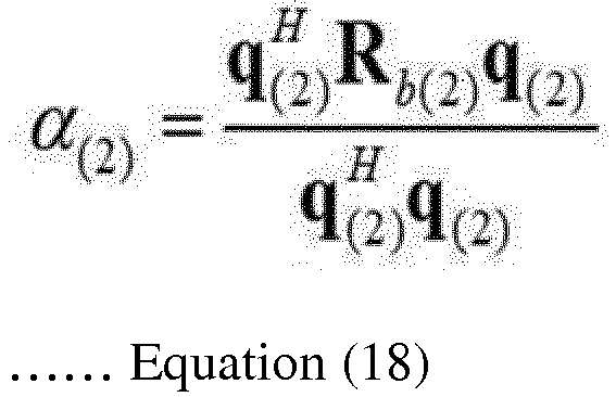
- the appropriate sound source signal maximizes the acoustic brightness ⁇ (1) , ⁇ (2) of Equations 17 and 18 (acoustic brightness control), maximizes the acoustic contrast 1 ⁇ (1) , ⁇ (2) of Equations 19 and 20 (acoustic contrast 1 control) or maximizes the acoustic contrast 2 ⁇ ' (1) , ⁇ ' (2) of Equations 21 and 22 (acoustic contrast 2 control).
- the thus determined sound source signal corresponds to a control sound source signal which is a term used in the claims of the present invention.
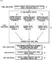
- the signal analyzer 400 measures the transfer function between the sound source signal of the sound source 100 and the sound signal of the sensor 200 (Step S1).
- the transfer function can be easily measured by the following simple method which is used generally.
- the simple method is to input, as a sound source signal, white noise with no correlation to the plurality of the speakers and is to separate the contribution of each sound source from the sound signal sensed by each microphone, so that the transfer function between the sound source signal of the sound source and the sound signal of the sensor is measured by only one measurement.
- the signal analyzer 400 determines an appropriate sound source signal by using the transfer function measured in step S1 and transmits the information on the determined sound source signal to the signal generator 300 (Step S2).
- the appropriate sound source signal maximizes the acoustic brightness ⁇ (1) , ⁇ (2) of Equations 17 and 18 (acoustic brightness control), maximizes the acoustic contrast 1 ⁇ (1) , ⁇ (2) of Equations 19 and 20 (acoustic contrast 1 control) or maximizes the acoustic contrast 2 ⁇ ' (1) , ⁇ ' (2) of Equations 21 and 22 (acoustic contrast 2 control).
- the thus determined sound source signal corresponds to a control sound source signal which is a term used in the claims of the present invention.
- the sound source signal for each frequency is determined.
- the sound source signal determined herein functions as a filter coefficient which filters an original sound signal (any sound intended to be heard in the bright zone (BZ)) in a below-described step 3.
- the signal generator 300 filters the original sound signal by the sound source signal determined in step 2 on the basis of the information transmitted from the signal analyzer 400, generates a sound source signal (filtered sound source signal) optimized for the bright zone (BZ), that is, generates a control sound source signal, and then transmits to the sound source 100 (Step S3).
- a sound source signal filtered sound source signal
- BZ bright zone
- the original sound signal is filtered by the determined sound source signal and a sound source signal optimized for the bright zone (BZ), that is, a control sound source signal is generated.
- BZ bright zone
- the sound source 100 outputs the sound source signal optimized by the signal generator 300 through the amplifier and speakers (Step S4). Accordingly, the bright zone (BZ) and the dark zone (DZ) may be generated in the acoustic space (Step S5).
- the acoustic brightness control allows the bright zone (BZ) to obtain the maximum sound pressure level with respect to the same input magnitude. Therefore, when the input magnitude cannot be increased or when the input magnitude is limited, the acoustic brightness control is more useful.
- the acoustic brightness control has a disadvantage in that the amount of the sound is relatively greater than those of the acoustic contrast 1 control and the acoustic contrast 2 control in a zone other than the bright zone (BZ). Therefore, when the amount of the sound doesn't have to be very small in a zone other than the bright zone (BZ), the acoustic brightness control is more efficient and effective.
- the acoustic contrast 1 control and the acoustic contrast 2 control shows a bright zone (BZ) production result more excellent than that of the acoustic brightness control. Also, for all small, medium, and large sound reproducing apparatuses, the acoustic contrast 1 control and the acoustic contrast 2 control are more excellent than the acoustic brightness control because the amount of the sound becomes very small in a zone other than the bright zone (BZ).
- a vehicle AVN system 1000 capable of selecting a plurality of the sound sources and of individually setting the focusing zone (i.e., the location of the bright zone (BZ)) of each of the selected sound sources will be described on the basis of the above-described generation principle of the bright zone (BZ).
- Fig. 4a is a block diagram showing a configuration of the vehicle AVN system 1000 according to the embodiment of the present invention.
- the vehicle AVN system 1000 according to the embodiment of the present invention includes a processor 1100, a user operation unit 1200, a storage 1300, a multi-channel amplifier 1400, and source providers 1500-1 to 1500-n.
- the source providers 1500-1 to 1500-n have a function of receiving the sound source.
- the source providers 1500-1 to 1500-n may include, for example, at least one of sound source input modules such as a CD module, a radio module, a navigation module, an AUX module, a DVD module, a DMB module, a Bluetooth module, or a USB module.
- the user operation unit 1200 has a function of receiving the selection of a sound source to be output through the speaker provided in the vehicle among the n number of the sound sources input from the source providers 1500-1 to 1500-n. Besides, the user operation unit 1200 has a function of receiving the selection of the focusing zone (corresponding to the above-described bright zone (BZ)) where the output of the selected sound source is focused.
- the focusing zone corresponding to the above-described bright zone (BZ)
- the user operation unit 1200 may be implemented by a means such as a touch screen, etc., may display the type of the sound source input from the source providers 1500-1 to 1500-n in the form of text, image, or icon, and may display a zone where the output of the sound source is focused, thereby allowing the user to easily select the sound source and focusing zone. Also, in another embodiment, the user operation unit 1200 may be implemented by a means such as a jog-shuttle, a switch, a button, or the like included in the AVN device in the vehicle.
- the user operation unit 1200 may be implemented by a separate operation means excluded from the AVN device in the vehicle.
- the user operation unit 1200 may be an operation means which is connected to the AVN device in the vehicle in a wired or wireless manner.
- Fig. 4b shows an embodiment where the user operation unit 1200 is implemented by a smartphone.
- the user operation unit 1200 implemented by a smartphone may be connected to the processor 1100 in a wireless manner and may use various communication methods such as WiFi, Bluetooth, ZigBee, Near Field Communication (NFC), etc. Therefore, the user operation unit 1200 and the processor 1100 may include a wireless communication module respectively.
- the sound source and the focusing zone which have been selected by the wirelessly connected user operation unit 1200 are transmitted to the processor 1100.
- the processor 110 may be used to control the sound in the vehicle on the basis of the signal received from the user operation unit 1200.
- the user operation unit 1200 may be implemented by a wirelessly connected operation means, for example, a variety of mobile terminals, a remote controller using an infrared signal, etc., as well as the smartphone.
- the user operation unit 1200 may be also implemented by a wired operation means.
- the user operation unit 1200 may be a jog-shuttle, a switch, a button, etc., which are provided in a steering wheel of the vehicle or may be an operation means separately provided on the seat zone (each seat armrest, door wall, rear side of the driver seat, rear side of the passenger seat, console box, etc.) in the vehicle, on the head lining, on the center fascia, on the dashboard, etc.
- the processor 1100 has a function of generating the sound source signal on the basis of the sound source and the focusing zone selected by the user operation unit 1200.
- the processor 1100 functions as the signal analyzer 400 and the signal generator 300 which have been described with reference to Fig. 3 . That is, the processor 1100 filters the sound source selected by the user by using the filter coefficient which maximizes a ratio between the spatially averaged acoustic energy of the focusing zone selected by the user and the spatially averaged acoustic energy of a zone other than the focusing zone, and then generates the sound source signal.
- the storage 1300 stores the filter coefficient for generating the sound source signal. That is, the storage 1300 stores the filter coefficient calculated by the method described with reference to Figs. 1 and 2a to 2c .
- the storage 1300 may store the filter coefficient in the form of a look-up table shown in Fig. 5 .
- the interior space of the vehicle may be divided into a plurality of zones where the output of the sound source can be focused.
- the filter coefficient corresponding to the plurality of the divided zones for example, a driver seat zone (FL), a passenger seat zone (FR), a rear left seat zone (RL), and a rear right seat zone (RR) may be defined in the look-up table.
- the focusing zone and the filter coefficient corresponding to the focusing zone are stored in the look-up table stored in the storage 1300.
- the processor 1100 filters the first sound source 1500-1 on the basis of the filter coefficient 1 (FC1) and then generates the sound source signal.
- the processor 1100 filters the second sound source 1500-2 on the basis of the filter coefficient 5 (FC5) and then generates the sound source signal.
- the storage method of the storage 1300 is not limited to the look-up table of Fig. 5 .
- the storage 1300 may store the filter coefficient by using various methods.
- the multi-channel amplifier 1400 has a function of dividing the generated sound source signal into multi-channels and amplifying, and then outputting.
- the multi-channel amplifier 1400 may simultaneously or selectively output the sound source signal corresponding to each of the sound sources.
- the filter coefficient 8 FC8
- the filter coefficient 1 FC1
- the multi-channel amplifier 1400 simultaneously outputs the filtered sound source signals respectively
- all of the first sound source 1500-1 and second sound source 1500-2 can be heard in the driver seat zone (FL) and only the first sound source 1500-1 can be heard in the other zones.
- the first sound source 1500-1 is a music sound
- the second sound source 1500-2 is a navigation sound
- the music can be appreciated in a zone other than the driver seat zone (FL) without interference caused by the navigation sound.
- the user may select the sound source signal to be output through the multi-channel amplifier 1400 by using the user operation unit 1200.
- the sound source signal can be heard only in the focusing zone corresponding to the specific sound source signal.
- the focusing zones of the music sound and the navigation sound are set to the driver seat zone (FL)
- the driver wants to focus on the navigation sound only the navigation sound can be selectively output by operating the user operation unit 1200.
- Fig. 6 is a view showing the user operation unit 1200 of the vehicle AVN system 1000 according to the embodiment of the present invention.
- the user operation unit 1200 may be a touch screen equipped with a display (not shown) and a touch panel (not shown).
- a plurality of zones where the sound source input from the source providers 1500-1 to 1500-n and the output of the sound source are focused are displayed on the display (not shown) in the form of text, image or icon, etc.
- the user may select the sound source or the focusing zone while viewing the text, image, or icon, etc., displayed on the display. That is, when the user touches the display (not shown), the touch panel (not shown) detects the user's selection of the sound source and the focusing zone on the basis of a touch signal of the user.
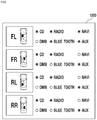
- the user operation unit 1200 displays the focusing zone on the left side thereof and displays the plurality of the sound sources on the right side thereof.
- the plurality of the sound sources may be displayed in the form of a radio button.
- the user may select the sound source to be output in each of the focusing zones. That is, the touch panel (not shown) of the user operation unit 1200 may detect the position of the touch applied by the user and determine the user's selection of the sound source and the focusing zone.
- a sound to be input through CD, radio, navigation, Bluetooth, and AUX terminal is selected as the sound source to be focused on the driver seat zone (FL).
- a sound to be input through CD, radio, DMB, and AUX terminal is selected as the sound source to be focused on the passenger seat zone (FR).
- a sound to be input through CD, radio, and AUX terminal is selected as the sound source to be focused on the rear left seat zone (RL) and the rear right seat zone (RR).
- a call voice and navigation sound through Bluetooth are heard only by a driver who is located in the driver seat zone (FL) and a DMB sound is heard only by a passenger who is located in the passenger seat zone (FR).
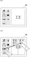
- Figs. 7a to 7c are views showing the user operation unit 1200 of the vehicle AVN system 1000 according to another embodiment of the present invention.
- the user operation unit 1200 may display the plurality of the sound sources on the left side thereof and the focusing zone on the right side thereof.
- the plurality of the sound sources may be input from a plurality of the source providers such as a CD module, a Bluetooth module, a navigation module, a DVD module, a DMB module, a radio module, and an AUX module.
- the user may select a larger number of the sound sources if necessary.
- the focusing zone may be, as described above, divided into the driver seat zone (FL), the passenger seat zone (FR), the rear left seat zone (RL), and the rear right seat zone (RR). However, there is no limitation to this.
- the focusing zone may be divided into a smaller or larger number of zones than this.
- the user may set the focusing zone by dragging one of the sound sources displayed on the left side of the user operation unit 1200 to one of the focusing zones displayed on the right side of the user operation unit 1200.
- the plurality of the sound sources may be selected for one focusing zone.
- one sound source may be set for a plurality of the focusing zones.
- a CD sound, an AUX sound, a navigation sound, a FM sound, and a Bluetooth sound are focused on the driver seat zone (FL)
- a CD sound, an AUX sound, a DMB sound, and a FM sound are focused on the passenger seat zone (FR)
- only a CD sound, an AUX sound, and a FM sound are focused on the rear left seat zone (RL) and the rear right seat zone (RR).
- the user is able to very easily set the sound source and the focusing zone in various ways described above. Also, as described above, the user is able to selectively turn on/off the output of each sound source by operating the user operation unit 1200.
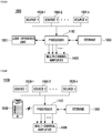
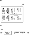
- Fig. 8a is a block diagram showing a configuration of a vehicle AVN system 2000 according to another embodiment of the present invention.
- the vehicle AVN system 2000 shown in Fig. 8a includes a vehicle AVN device 2300 and an external processor 2100.
- the vehicle AVN system 2000 shown in Fig. 8a includes the external processor.
- the vehicle AVN device 2300 may include a plurality of the source providers for receiving the sound source, include the user operation unit which allows the user to select at least one of a plurality of the sound sources input from the plurality of the source providers and to select the focusing zone of the sound source, and include the multi-channel amplifier.
- the external processor 2100 is connected to the vehicle AVN device 2300 in a wired or wireless manner and generates the sound source signal for focusing the output of the selected sound source on the focusing zone, and then outputs the sound source signal through the multi-channel amplifier.
- the external processor 2100 filters the selected sound source on the basis of the filter coefficient corresponding to the focusing zone selected by the user operation unit, and then generates the sound source signal.
- the external processor 2100 filters the sound source by using the filter coefficient which maximizes a ratio between the spatially averaged acoustic energy of the focusing zone selected by the user operation unit and the spatially averaged acoustic energy of a zone other than the selected focusing zone, and then generates the sound source signal.
- an in-vehicle sound control method according to the embodiment of the present invention can be applied to any existing vehicle because the vehicle AVN device 2300 provided in the vehicle can be used as it is.
- the user operation unit 2200 in the configuration of Fig. 8a is separately provided.
- the user operation unit 2200 of Fig. 8b may include a wireless communication module (not shown). At least one of the plurality of the sound sources input from the plurality of the source providers and a selection signal for the focusing zone of the sound source are transmitted to the external processor 2100 through the wireless communication module (not shown) by the user operation unit 2200.
- the external processor 2100 generates the sound source signal on the basis of the selection signal received from the separately provided user operation unit 2200 and outputs the sound source signal by using the multi-channel amplifier provided in the vehicle AVN device 2300.
- Fig. 8b shows that the user operation unit 2200 is implemented by a tablet PC.
- the user operation unit 2200 can be wirelessly connected to the vehicle AVN device 2300 by using various communication methods such as WiFi, Bluetooth, ZigBee, and Near Field Communication (NFC), etc.
- various communication methods such as WiFi, Bluetooth, ZigBee, and Near Field Communication (NFC), etc.
- the user operation unit 2200 may be implemented by a wirelessly connected operation means such as various mobile terminals, a remote controller using an infrared signal, etc., or may be implemented by a wired operation means.
- the user operation unit 2200 may be a jog-shuttle, a switch, a button, etc., which are provided in a steering wheel of the vehicle or may be an operation means separately provided on the seat zone (each seat armrest, door wall, rear side of the driver seat, rear side of the passenger seat, console box, etc.) in the vehicle, on the head lining, on the center fascia, on the dashboard, etc.
- Fig. 9 is a flowchart of the in-vehicle sound control method according to the embodiment of the present invention.
- various sound sources are input through the plurality of the source providers 1500-1 to 1500-n (S1600). Then, at least one of the plurality of the sound sources input through the plurality of the source providers 1500-1 to 1500-n and user's selection of the focusing zone of the sound source are detected by the user operation unit 1200 (S1610).
- the displaying of the plurality of the sound sources and the plurality of the focusing zones may be performed first.
- the sound source signal for focusing the output of the selected sound source on the focusing zone is generated (S1620).
- the sound source signal is generated by filtering the sound source selected by using the filter coefficient which maximizes a ratio between the spatially averaged acoustic energy of the focusing zone and the spatially averaged acoustic energy of a zone other than the focusing zone.
- one or the plurality of the sound source signals are simultaneously or selectively output by the multi-channel amplifier 1400, so that the output of the selected sound source can be focused on the focusing zone.
- the in-vehicle sound control method it is possible to individually control the focusing zone of each sound output within the vehicle, and particularly to easily select and control the focusing zone of each sound without changing the location of the speaker within the vehicle. Further, according to the in-vehicle sound control method according to the embodiment of the present invention, the sound source and the focusing zone within the vehicle can be selected and controlled only by adding an external processor without replacing the AVN device provided in the vehicle.
Landscapes
- Engineering & Computer Science (AREA)
- Mechanical Engineering (AREA)
- Physics & Mathematics (AREA)
- Acoustics & Sound (AREA)
- Signal Processing (AREA)
- General Engineering & Computer Science (AREA)
- Theoretical Computer Science (AREA)
- Human Computer Interaction (AREA)
- General Physics & Mathematics (AREA)
- Fittings On The Vehicle Exterior For Carrying Loads, And Devices For Holding Or Mounting Articles (AREA)
- Circuit For Audible Band Transducer (AREA)
Abstract
Description
- The present disclosure relates to an in-vehicle sound control method and a vehicle audio video navigation (AVN) system, and more particularly to an in-vehicle sound control method capable of individually setting a listening location of various sound sources which can be output in a vehicle and a vehicle audio video navigation (AVN) system.
- In addition to the development of an AVN system provided in a vehicle, more and more attentions are paid to a sound control in the vehicle. For example, a sound of a portable device such as a mobile terminal, a PMP, an MP3 player, etc., is output from a speaker through a wireless and wired connection means such as Bluetooth, AUX, etc. In particular, active research is being conducted to control the sound output from the speaker in the vehicle in accordance with a location in the vehicle (a rider's position).
- A sound control technology includes, for example, a sound field reproduction method, an active noise control method which decreases a sound amount of a space by using a plurality of active sound sources, a method for changing an interval between the sound sources arranged in a specific shape, and a method for increasing a sound power which is radiated at a specific angle by changing a time delay between the sound sources and the magnitude of the sound input.
- However, it is difficult to apply a mathematical solution for a specific sound source array to any sound source. For this reason, optimization research has been conducted to obtain a maximum directionality in a particular direction through the assumption of any sound source array. However, this research has assumed only any sound source array and is not suitable to be applied to a common listening space having radiation forms of various sound sources, sound reflection, and sound absorption.
- Furthermore,
US patent 5,802,190 (Title of the invention: Linear speaker array) discloses a technology for controlling indirect characteristics such as directionality by using a limited assumption which ignores the distance to the listener or reflection, etc.US patent 5,910,990 (Title of the invention: Apparatus and method for automatic equalization of personal multi-channel audio system) discloses a method for reproducing a signal without distortion by using transfer function. - Also, Korean Patent Application No.
10-2008-0125309 - The above-mentioned documents have a problem in that it is difficult to control a zone on which the sound is intended to be focused in the environment, for example, a vehicle, where the locations of the speakers are fixed. That is, a hardware-based change is necessarily required because the sound cannot be focused on the specific zone by using existing mounted speakers.
- As such, the conventional method for controlling the sound in a space by using a plurality of the sound sources simply changes the time delay between the sound sources and the magnitude of the sound input, and only changes the directionality of the sound source by using a restricted type of the sound source array, without considering a rider's position in the vehicle.
- For example, when a driver makes a voice call through Bluetooth, other riders in the vehicle do not need to hear the call contents. That is, it is necessary for the other calling party's voice output from the speaker to be focused on the driver. However, the above-mentioned method cannot focus the Bluetooth voice on the position of the driver because the locations of the speakers in the vehicle are fixed.
- Furthermore, when an alarm sound is output from a navigation apparatus during the playing of music through the AVN system in the vehicle, there is a case where the music and the alarm sound from the navigation apparatus are simultaneously output from the same speaker. Here, there is a need to control the position where the output of the music is focused and the position where the alarm sound of the navigation apparatus is focused.
- As such, there are high technical requirements for individually controlling the focusing locations of call voice, music sound, and navigation sound, etc., which are output within the vehicle.
- The embodiment of the present invention is designed to overcome the above problems. The object of the present invention is to provide an in-vehicle sound control method capable of individually selecting, adjusting, and controlling a focusing zone of each sound output within a vehicle, and a vehicle audio video navigation (AVN) system. Also, the object of the present invention is to provide the in-vehicle sound control method capable of easily selecting and controlling the focusing zone of the sound output within the vehicle by using existing mounted speakers without changing the location of the speaker within the vehicle, and the vehicle audio video navigation (AVN) system.
- One embodiment is a vehicle audio video navigation (AVN) system may be provided that includes: a plurality of source providers which receives a sound source; a user operation unit which selects at least one of a plurality of the sound sources input from the plurality of the source providers and selects a focusing zone of the sound source; a processor which generates a sound source signal for focusing an output of the selected sound source on the focusing zone; and a multi-channel amplifier which outputs the sound source signal.
- The multi-channel amplifier may simultaneously or selectively output the sound source signal generated for each of the plurality of the sound sources.
- An interior space of the vehicle may be divided into a plurality of the focusing zones. The vehicle AVN system may further include a storage which stores a filter coefficient corresponding to each of the plurality of the focusing zones.
- The processor may filter the selected sound source on the basis of the filter coefficient corresponding to the focusing zone selected by the user operation unit, and may generate the sound source signal.
- The user operation unit may be a touch screen which detects the user's selection of the sound source and the focusing zone on the basis of a touch signal applied by the user.
- The user operation unit may display a plurality of the focusing zones where the plurality of the sound sources and the output of the sound source are focused.
- The source provider may include a CD module, a radio module, a navigation module, an AUX module, a DVD module, a DMB module, a Bluetooth module, or a USB module.
- The processor may filter the sound source by using a filter coefficient which maximizes a ratio between a spatially averaged acoustic energy of the focusing zone selected by the user operation unit and a spatially averaged acoustic energy of a zone other than the selected focusing zone, and then may generate the sound source signal.
- The user operation unit may include a wireless communication module. At least one of the plurality of the sound sources input from the plurality of the source providers and a selection signal for the focusing zone of the sound source may be transmitted to the processor through the wireless communication module by the user operation unit.
- The user operation unit may be provided in at least one of seat zones provided in a vehicle.
- Another embodiment is a vehicle audio video navigation (AVN) system including a vehicle AVN device and an external processor. The vehicle AVN device includes: a plurality of source providers which receives a sound source; a user operation unit which selects at least one of a plurality of the sound sources input from the plurality of the source providers and selects a focusing zone of the sound source; and a multi-channel amplifier. The external processor is connected to the vehicle AVN device, generates a sound source signal for focusing an output of the selected sound source on the focusing zone, and outputs the sound source signal through the multi-channel amplifier.
- The external processor may filter the selected sound source on the basis of the filter coefficient corresponding to the focusing zone selected by the user operation unit, and may generate the sound source signal.
- The external processor may filter the sound source by using a filter coefficient which maximizes a ratio between a spatially averaged acoustic energy of the focusing zone selected by the user operation unit and a spatially averaged acoustic energy of a zone other than the selected focusing zone, and then may generate the sound source signal.
- The user operation unit may include a wireless communication module. At least one of the plurality of the sound sources input from the plurality of the source providers and a selection signal for the focusing zone of the sound source may be transmitted to the external processor through the wireless communication module by the user operation unit.
- The user operation unit may be provided in at least one of seat zones provided in a vehicle.
- Further another embodiment is an in-vehicle sound control method including: receiving various sound sources through a plurality of source providers; detecting at least one of the plurality of the sound sources input through the plurality of the source providers and user's selection of a focusing zone of the sound source; generating a sound source signal for focusing an output of the selected sound source on the focusing zone; and outputting the generated sound source signal.
- The in-vehicle sound control method may further include displaying the plurality of the sound sources and a plurality of the focusing zones where the output of the sound source is focused.
- The outputting the generated sound source signal may output simultaneously or selectively the respective sound source signals corresponding to the plurality of the sound sources.
- An interior space of the vehicle is divided into a plurality of the focusing zones. The in-vehicle sound control method may further include storing a filter coefficient corresponding to each of the plurality of the focusing zones.
- The generating a sound source signal may filter the sound source on the basis of the filter coefficient corresponding to the focusing zone, and may generate the sound source signal.
- The filter coefficient may maximize a ratio between a spatially averaged acoustic energy of the focusing zone selected by the user operation unit and a spatially averaged acoustic energy of a zone other than the focusing zone.
- According to the in-vehicle sound control method according to the embodiment of the present invention, it is possible to individually control the focusing zone of each sound output within the vehicle, and particularly to easily select and control the focusing zone of each sound without changing the location of the speaker within the vehicle. Further, according to the in-vehicle sound control method according to the embodiment of the present invention, the sound source and the focusing zone within the vehicle can be selected and controlled only by adding an external processor without replacing the AVN device provided in the vehicle.
-
-
Fig. 1 is a schematic view of a system for setting a focusing zone; -
Figs. 2a to 2c are views showing an example in which the system ofFig. 1 is implemented in a vehicle; -
Fig. 3 is a flowchart for describing a method for setting a bright zone (BZ), i.e., the focusing zone and a dark zone (DZ), i.e., a zone other than the bright zone (BZ); -
Fig. 4a is a block diagram showing a configuration of a vehicle AVN system according to an embodiment of the present invention; -
Fig. 4b is a block diagram showing a configuration of a vehicle AVN system according to another embodiment of the present invention; -
Fig. 5 is a view showing a look-up table stored in a storage of the vehicle AVN system according to the embodiment of the present invention; -
Fig. 6 is a view showing a user operation unit of the vehicle AVN system according to the embodiment of the present invention; -
Figs. 7a to 7c are views showing a user operation unit of a vehicle AVN system according to another embodiment of the present invention; -
Fig. 8a is a block diagram showing a configuration of the vehicle AVN system according to further another embodiment of the present invention; -
Fig. 8b is a block diagram showing a configuration of the vehicle AVN system according to the further another embodiment of the present invention; and -
Fig. 9 is a flowchart of an in-vehicle sound control method according to the embodiment of the present invention. - Specific embodiments of the present invention will be described in detail with reference to the accompanying drawings. The specific embodiments shown in the accompanying drawings will be described in enough detail that those skilled in the art are able to embody the present invention. Other embodiments other than the specific embodiments are mutually different, but do not have to be mutually exclusive. Additionally, it should be understood that the following detailed description is not intended to be limited.
- The detailed descriptions of the specific embodiments shown in the accompanying drawings are intended to be read in connection with the accompanying drawings, which are to be considered part of the entire written description. Any reference to direction or orientation is merely intended for convenience of description and is not intended in any way to limit the scope of the present invention.
-
Fig. 1 is a view schematically showing a configuration for focusing zone setting. - For convenience of description and understanding,
Fig. 1 schematically shows a means for transfer function measurement, such as an acoustic space, aspeaker 110, amicrophone 210, etc. However, actually, as shown inFigs. 2a to 2c , it is possible to measure the transfer function by using a greater number of themicrophones 210 andspeakers 110. Specifically, as shown inFigs. 2a to 2c , a focusing zone setting system may be composed of a plurality of the speakers having independent channels and the microphone having 30 channels which are spaced apart from each other by an interval of 4 cm and are arranged in the form of 6x5 array. The transfer function measurement may be performed in four seat zones, that is to say, a driver seat zone (front left, FL), a passenger seat zone (front right, FR), a rear left seat zone (RL), and a rear right seat zone (RR) shown inFig. 2a in the vehicle. However, this is just an embodiment. The setting system can be implemented in various ways in accordance with the size, internal spatial structure, location of the internal configuration, etc., of the vehicle. - Referring back to
Fig. 1 , in the acoustic space (herein, the interior space of the vehicle), a first speaker and a second speaker, which function as a sound source, are installed in any location. The first speaker and the second speaker do not include a bright zone (hereinafter, referred to as BZ) and a dark zone (hereinafter, referred to as DZ). However, there is no limitation to this. - The bright zone (BZ) means a zone where a sound output from the first speaker and the second speaker is heard above a threshold value. The dark zone (DZ) means a zone where a sound output from the first speaker and the second speaker is heard below the threshold value. Briefly describing, the bright zone (BZ) may be a zone where a sound can be heard and a zone where the sound source is focused by a user. The dark zone (DZ) may be a zone where a sound cannot be heard and a zone where the sound source is not focused by the user. However, the distinction between the bright zone (BZ) and the dark zone (DZ) is based on a contrast between sound pressure levels. Therefore, not only a sound may be controlled not to be heard in the dark zone (DZ), but also a small sound can be detected even in the dark zone (DZ).
- In
Fig. 1 , the bright zone (BZ) and the dark zone (DZ) are schematized and distinguished by a dotted circle. - The sound pressure p(
r j |r s,i ;ω) (a signal which is sensed by the microphone) at any pointr j generated by a first sound source and a second sound source can be represented by the followingEquation 1.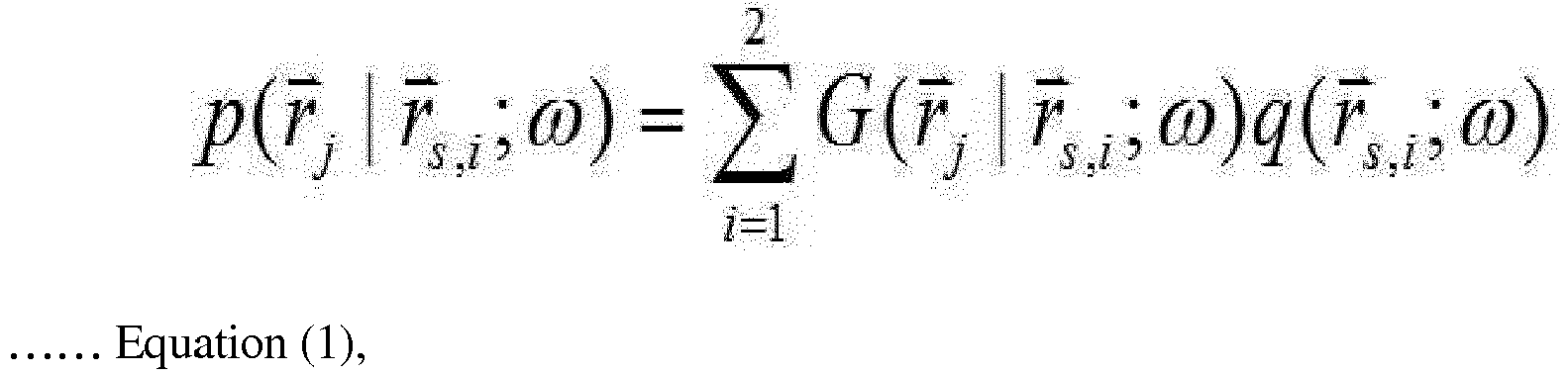
r j represents a j-th spatial point, andr s,i represents a location of an i-th sound source. Additionally, G(r j |r s,i ;ω) is a transfer function representing a relation betweenr j andr s,i . Here, the transfer function may be easily obtained by a definition of a mathematical model or an actual measurement. Equation (1) may be represented with respect to two points in the form of a matrix by the following Equation (2).
- Likewise, a first bright zone (BZ1), a second bright zone (BZ2), the dark zone (DZ), and a total sound zone (TZ) including the two foregoing zones are represented in the form of a matrix by the following Equations (3) to (5). The subscripts b, d, and t in Equations (3) to (5) represent the bright zone (BZ), the dark zone (DZ), and the total sound zone (TZ) respectively.


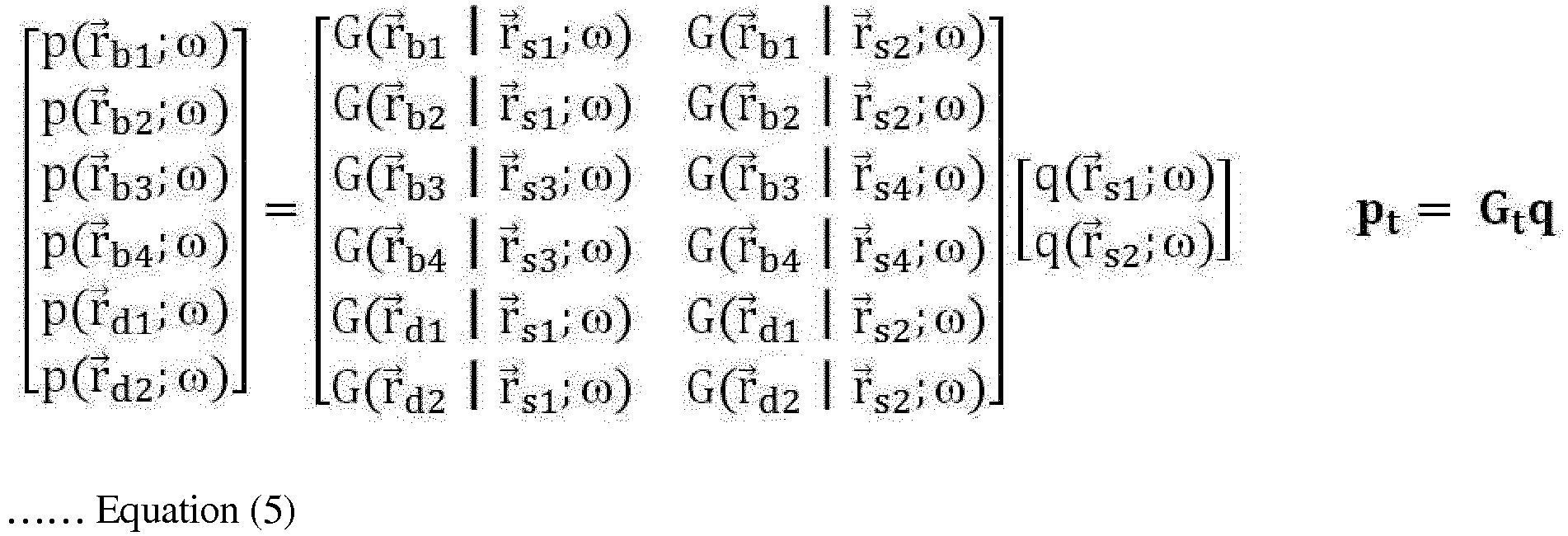
- In the next place, a variable representative of the space is defined as a spatially averaged acoustic energy in the embodiment of the present invention. The variable may be represented by the following Equation (6).

- The variable representative of the space is defined as the spatially averaged acoustic energy because it is difficult to express acoustic characteristics within a zone only by the sound pressure levels themselves of the respective points. In other words, in the embodiment of the present invention, it is considered that the spatially averaged acoustic potential energy of the bright zone (BZ), the spatially averaged acoustic energy of the dark zone (DZ), and the spatially averaged acoustic potential energy of the total sound zone (TZ) are sound pressure levels of each zone.
- In Equation (6), the matrixis defined as a correlation matrix which indicates how much interference each sound source causes in a defined zone. The figure of 2 means the number of the

microphones 210 in Equation (2) (seeFig. 1 ). For convenience of understanding, the embodiment of the present invention takes a simple example. However, actually, the numeric means the number of the microphones included within a defined zone. - Namely, when 30 microphones are used as shown in
Fig. 2c , the figure of 2 would be changed into 30. It is possible to represent the spatially averaged acoustic energy for the bright zone (BZ) and the dark zone (DZ), which is defined by this logic.

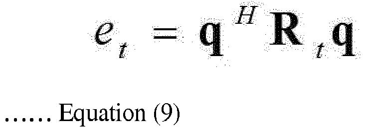
- Next, provided is a description of each of processes of generating a first sound source signal and a second sound source signal which are required so as to obtain a required control effect by using the sound pressure level of each zone, which is defined in Equations (7) to (9).
- The total magnitude of the input is defined as a sum of the absolute value of complex magnitude of the first sound source signal and the absolute value of complex magnitude of the second sound source signal. This can be referred to as a total magnitude of control effort. The total magnitude of input is represented by the following Equation (10).

- Here, |G 0|2 is the total magnitude of the input, that is to say, a normalizing constant which changes the control effort into the dimension of the spatially averaged acoustic energy.
- The contrast between the sound pressure level and the total magnitude of the input in the bright zone (BZ) can be represented as the following Equation (11) by using the Equations (7) and (10). This is defined as "acoustic brightness".

- Accordingly, the determination of the sound source signal for maximizing the contrast between the sound pressure level and the total magnitude of the input in the bright zone (BZ) corresponds to how to obtain the sound source signal for maximizing the value of α in the Equation (11).
- The Equation (11) can be formalized as a mathematical problem of maximizing Reyleigh quotient α. This is represented by the following Equation (12).

- As shown in the Equation (12), the obtaining of the sound source signal for maximizing the value of α is equal to the obtaining of a maximum eigenvalue of a generalized eigenvalue problem. Also, an eigenvector corresponding to the maximum eigenvalue becomes the first sound source signal and the second sound source signal.
- The input signal of the sound source for maximizing the contrast between the sound pressure level of the bright zone (BZ) and the sound pressure level of the dark zone (DZ) is considered. As with the case 1 (Determination of the sound source signal for maximizing the contrast between the sound pressure level of the bright zone (BZ) and total magnitude of the sound input), the sound pressure level of the bright zone (BZ) with respect to that of the dark zone (DZ) can be mathematically represented by the following Equation (13). This is defined as "
acoustic contrast 1".

- In the same manner as described above, the Equation (13) can be formalized as a problem of maximizing Reyleigh quotient β. As shown in the Equation (14), the obtaining of the sound source signal for maximizing the value of β is equal to the obtaining of a maximum eigenvalue of a generalized eigenvalue problem. Also, an eigenvector corresponding to the maximum eigenvalue becomes the first sound source signal and the second sound source signal.
- Therefore, while the conventional methods use the relation between a listener and the sound source in a limited form, the embodiment of the present invention uses a method for obtaining an optimized sound source control signal by analyzing all the transfer functions.
- As a result, unlike an active noise control method which only decreases the sound pressure level, the embodiment of the present invention is able to increase a relative difference of the sound pressure level in accordance with the zone. In other words, it is possible to perform control to increase the acoustic contrast between two different zones as well as the magnitude of the sound pressure level corresponding to the acoustic brightness.
- The sound source input signal for maximizing the contrast between the sound pressure level of the bright zone (BZ) and the sound pressure level of the total sound zone (TZ) will be described. As with the case 2 (Determination of the input signal for maximizing the contrast between the bright zone (BZ) and the dark zone (DZ)), the sound pressure level of the total sound zone (TZ) with respect to that of the dark zone (DZ) can be mathematically represented by the following Equation (15). This is defined as "
acoustic contrast 2".
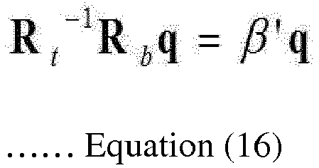
- In the same manner as described above, the Equation (15) can be formalized as a problem of maximizing Reyleigh quotient β'. As shown in the Equation (16), the obtaining of the sound source signal for maximizing the value of β' is equal to the obtaining of a maximum eigenvalue of a generalized eigenvalue problem. Also, an eigenvector corresponding to the maximum eigenvalue becomes the first sound source signal and the second sound source signal.
- Three kinds of methods for providing an independent acoustic environment to a plurality of the bright zones (BZ) will be described.
- [Method 1] In the first bright zone (BZ1), a ratio between the spatially averaged acoustic energy by the first sound source signal and a sum of the energies of the first sound source signal is intended to be maximized. Additionally, in the second bright zone (BZ2), a ratio between the spatially averaged acoustic energy by the second sound source signal and a sum of the energies of the second sound source signal is intended to be maximized.
- In this case, the input signal is generated differently for each bright zone. This is represented as follows.

- [Method 2] In the first bright zone (BZ1), a ratio between the spatially averaged acoustic energy by the first sound source signal and the spatially averaged acoustic energy of remaining zone other than the first bright zone (BZ1) is intended to be maximized. Simultaneously, in the second bright zone (BZ2), a ratio between the spatially averaged acoustic energy by the second sound source signal and the spatially averaged acoustic energy of remaining zone other than the second bright zone (BZ2) is intended to be maximized.
- In this case, the input signal is generated differently for each bright zone (BZ). This is represented as follows.


- [Method 3] When a plurality of the bright zones (BZ) are provided, a ratio between the spatially averaged acoustic energy by the first sound source signal and the spatially averaged acoustic energy of the total zone including the first bright zone (BZ1) is intended to be maximized in the first bright zone (BZ1). Simultaneously, a ratio between the spatially averaged acoustic energy by the second sound source signal and the spatially averaged acoustic energy of the total zone including the second bright zone (BZ2) is intended to be maximized in the second bright zone (BZ2).
- In this case, the input signal is generated differently for each bright zone (BZ). This is represented as follows.
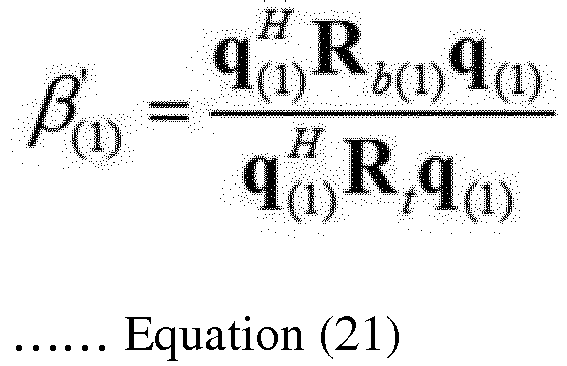

- In the above-described methods, the input signal is generated differently for each bright zone (BZ). The signal input to the first sound source and the second sound source is commonly expressed by the following Equation (23).

- In this case, it is possible to create a plurality of independent acoustic environments in which a reproduced sound by the first input signal exists in the first bright zone (BZ1) and a reproduced sound by the second input signal exists in the second bright zone (BZ2).
- In summary of the theoretical foregoing, while the conventional methods use the relation between a listener and the sound source in a limited form, the embodiment of the present invention uses a method for obtaining an optimized sound source signal by analyzing all the transfer functions.
- As a result, unlike an active noise control method which only decreases the sound pressure level, the embodiment of the present invention increases a relative difference of the sound pressure level in accordance with the zone in the acoustic space. In other words, the embodiment of the present invention performs control to increase the acoustic contrast between two different zones as well as the magnitude of the sound pressure level corresponding to the acoustic brightness.
- The method for forming the bright zone (BZ) and the dark zone (DZ) will be described in more detail with greater reference to
Fig. 3 . - As shown in
Fig. 1 , the configuration which measures the transfer function and sets the focusing zone includes asound source 100, asensor 200, asignal generator 300, and asignal analyzer 400. - The
sound source 100 includes a plurality of thespeakers 110 corresponding to a plurality of the sound sources and amulti-channel audio amplifier 120 which drives the plurality of the speakers. Thesensor 200 includes a plurality of themicrophones 210 installed in the bright zone (BZ) and the dark zone (DZ). Thesignal generator 300 includes amulti-channel signal generator 310 which gives a synchronized individual sound source signal to each speaker through the multi-channel audio amplifier of the sound source. Thesignal analyzer 400 includes amulti-channel signal analyzer 410 which measures a transfer function between a sound source signal q input to thesound source 100 and a sound signal p sensed by thesensor 200, determines an appropriate sound source signal, and then transmits the information on the determined sound source signal to themulti-channel signal generator 310 of thesignal generator 300. - Here, the appropriate sound source signal maximizes the acoustic brightness α(1),α(2) of Equations 17 and 18 (acoustic brightness control), maximizes the
acoustic contrast 1 β(1),β(2) of Equations 19 and 20 (acoustic contrast 1 control) or maximizes theacoustic contrast 2 β'(1),β'(2) of Equations 21 and 22 (acoustic contrast 2 control). Also, the thus determined sound source signal corresponds to a control sound source signal which is a term used in the claims of the present invention. - Referring to
Fig. 3 , thesignal analyzer 400 measures the transfer function between the sound source signal of thesound source 100 and the sound signal of the sensor 200 (Step S1). In the measurement of the transfer function, a large amount of measurement are required according to the number of the speakers and the number of the microphones. Therefore, the transfer function can be easily measured by the following simple method which is used generally. - The simple method is to input, as a sound source signal, white noise with no correlation to the plurality of the speakers and is to separate the contribution of each sound source from the sound signal sensed by each microphone, so that the transfer function between the sound source signal of the sound source and the sound signal of the sensor is measured by only one measurement.
- Next, the
signal analyzer 400 determines an appropriate sound source signal by using the transfer function measured in step S1 and transmits the information on the determined sound source signal to the signal generator 300 (Step S2). - Here, the appropriate sound source signal maximizes the acoustic brightness α(1),α(2) of Equations 17 and 18 (acoustic brightness control), maximizes the
acoustic contrast 1 β(1),β(2) of Equations 19 and 20 (acoustic contrast 1 control) or maximizes theacoustic contrast 2 β'(1),β'(2) of Equations 21 and 22 (acoustic contrast 2 control). Also, the thus determined sound source signal corresponds to a control sound source signal which is a term used in the claims of the present invention. - Here, a single frequency has been described. Furthermore, in the case of a plurality of frequencies, it can be understood that the sound source signal for each frequency is determined. Also, the sound source signal determined herein functions as a filter coefficient which filters an original sound signal (any sound intended to be heard in the bright zone (BZ)) in a below-described
step 3. - Next, the
signal generator 300 filters the original sound signal by the sound source signal determined instep 2 on the basis of the information transmitted from thesignal analyzer 400, generates a sound source signal (filtered sound source signal) optimized for the bright zone (BZ), that is, generates a control sound source signal, and then transmits to the sound source 100 (Step S3). - Here, a single frequency has been described. Furthermore, in the case of a plurality of frequencies, it can be understood that, for each frequency, the original sound signal is filtered by the determined sound source signal and a sound source signal optimized for the bright zone (BZ), that is, a control sound source signal is generated.
- Next, the
sound source 100 outputs the sound source signal optimized by thesignal generator 300 through the amplifier and speakers (Step S4). Accordingly, the bright zone (BZ) and the dark zone (DZ) may be generated in the acoustic space (Step S5). - The acoustic brightness control allows the bright zone (BZ) to obtain the maximum sound pressure level with respect to the same input magnitude. Therefore, when the input magnitude cannot be increased or when the input magnitude is limited, the acoustic brightness control is more useful.
- However, the acoustic brightness control has a disadvantage in that the amount of the sound is relatively greater than those of the
acoustic contrast 1 control and theacoustic contrast 2 control in a zone other than the bright zone (BZ). Therefore, when the amount of the sound doesn't have to be very small in a zone other than the bright zone (BZ), the acoustic brightness control is more efficient and effective. - As long as the input magnitude is not extremely limited, the
acoustic contrast 1 control and theacoustic contrast 2 control shows a bright zone (BZ) production result more excellent than that of the acoustic brightness control. Also, for all small, medium, and large sound reproducing apparatuses, theacoustic contrast 1 control and theacoustic contrast 2 control are more excellent than the acoustic brightness control because the amount of the sound becomes very small in a zone other than the bright zone (BZ). - Hereinafter, a
vehicle AVN system 1000 capable of selecting a plurality of the sound sources and of individually setting the focusing zone (i.e., the location of the bright zone (BZ)) of each of the selected sound sources will be described on the basis of the above-described generation principle of the bright zone (BZ). -
Fig. 4a is a block diagram showing a configuration of thevehicle AVN system 1000 according to the embodiment of the present invention. Thevehicle AVN system 1000 according to the embodiment of the present invention includes aprocessor 1100, auser operation unit 1200, astorage 1300, amulti-channel amplifier 1400, and source providers 1500-1 to 1500-n. - First, the source providers 1500-1 to 1500-n have a function of receiving the sound source. The source providers 1500-1 to 1500-n may include, for example, at least one of sound source input modules such as a CD module, a radio module, a navigation module, an AUX module, a DVD module, a DMB module, a Bluetooth module, or a USB module.
- The
user operation unit 1200 has a function of receiving the selection of a sound source to be output through the speaker provided in the vehicle among the n number of the sound sources input from the source providers 1500-1 to 1500-n. Besides, theuser operation unit 1200 has a function of receiving the selection of the focusing zone (corresponding to the above-described bright zone (BZ)) where the output of the selected sound source is focused. - The
user operation unit 1200 may be implemented by a means such as a touch screen, etc., may display the type of the sound source input from the source providers 1500-1 to 1500-n in the form of text, image, or icon, and may display a zone where the output of the sound source is focused, thereby allowing the user to easily select the sound source and focusing zone. Also, in another embodiment, theuser operation unit 1200 may be implemented by a means such as a jog-shuttle, a switch, a button, or the like included in the AVN device in the vehicle. - Meanwhile, the
user operation unit 1200 may be implemented by a separate operation means excluded from the AVN device in the vehicle. For example, theuser operation unit 1200 may be an operation means which is connected to the AVN device in the vehicle in a wired or wireless manner. -
Fig. 4b shows an embodiment where theuser operation unit 1200 is implemented by a smartphone. Theuser operation unit 1200 implemented by a smartphone may be connected to theprocessor 1100 in a wireless manner and may use various communication methods such as WiFi, Bluetooth, ZigBee, Near Field Communication (NFC), etc. Therefore, theuser operation unit 1200 and theprocessor 1100 may include a wireless communication module respectively. - The sound source and the focusing zone which have been selected by the wirelessly connected
user operation unit 1200 are transmitted to theprocessor 1100. Theprocessor 110 may be used to control the sound in the vehicle on the basis of the signal received from theuser operation unit 1200. - The
user operation unit 1200 may be implemented by a wirelessly connected operation means, for example, a variety of mobile terminals, a remote controller using an infrared signal, etc., as well as the smartphone. Theuser operation unit 1200 may be also implemented by a wired operation means. For example, theuser operation unit 1200 may be a jog-shuttle, a switch, a button, etc., which are provided in a steering wheel of the vehicle or may be an operation means separately provided on the seat zone (each seat armrest, door wall, rear side of the driver seat, rear side of the passenger seat, console box, etc.) in the vehicle, on the head lining, on the center fascia, on the dashboard, etc. - The
processor 1100 has a function of generating the sound source signal on the basis of the sound source and the focusing zone selected by theuser operation unit 1200. In other words, theprocessor 1100 functions as thesignal analyzer 400 and thesignal generator 300 which have been described with reference toFig. 3 . That is, theprocessor 1100 filters the sound source selected by the user by using the filter coefficient which maximizes a ratio between the spatially averaged acoustic energy of the focusing zone selected by the user and the spatially averaged acoustic energy of a zone other than the focusing zone, and then generates the sound source signal. - The
storage 1300 stores the filter coefficient for generating the sound source signal. That is, thestorage 1300 stores the filter coefficient calculated by the method described with reference toFigs. 1 and2a to 2c . For example, thestorage 1300 may store the filter coefficient in the form of a look-up table shown inFig. 5 . Here, the interior space of the vehicle may be divided into a plurality of zones where the output of the sound source can be focused. The filter coefficient corresponding to the plurality of the divided zones, for example, a driver seat zone (FL), a passenger seat zone (FR), a rear left seat zone (RL), and a rear right seat zone (RR) may be defined in the look-up table. - As shown in
Fig. 5 , the focusing zone and the filter coefficient corresponding to the focusing zone are stored in the look-up table stored in thestorage 1300. When the first sound source 1500-1 is focused on the driver seat zone (FL), that is to say, when the bright zone (BZ) for the first sound source 1500-1 is set to the driver seat zone (FL), theprocessor 1100 filters the first sound source 1500-1 on the basis of the filter coefficient 1 (FC1) and then generates the sound source signal. - When the second sound source 1500-2 is focused on the driver seat zone (FL) and the passenger seat zone (FR), that is to say, when the bright zone (BZ) for the second sound source 1500-2 is set to the driver seat zone (FL) and the passenger seat zone (FR), the
processor 1100 filters the second sound source 1500-2 on the basis of the filter coefficient 5 (FC5) and then generates the sound source signal. However, the storage method of thestorage 1300 is not limited to the look-up table ofFig. 5 . Thestorage 1300 may store the filter coefficient by using various methods. - The
multi-channel amplifier 1400 has a function of dividing the generated sound source signal into multi-channels and amplifying, and then outputting. Themulti-channel amplifier 1400 may simultaneously or selectively output the sound source signal corresponding to each of the sound sources. - For example, in a case where all the seat zones (FL, FR, RL, and RR) are set to the focusing zone by applying the filter coefficient 8 (FC8) to the first sound source 1500-1 and only the driver seat zone (FL) is set to the focusing zone by applying the filter coefficient 1 (FC1) to the second sound source 1500-2, when the
multi-channel amplifier 1400 simultaneously outputs the filtered sound source signals respectively, all of the first sound source 1500-1 and second sound source 1500-2 can be heard in the driver seat zone (FL) and only the first sound source 1500-1 can be heard in the other zones. Specifically, if the first sound source 1500-1 is a music sound and the second sound source 1500-2 is a navigation sound, the music can be appreciated in a zone other than the driver seat zone (FL) without interference caused by the navigation sound. - Also, the user may select the sound source signal to be output through the
multi-channel amplifier 1400 by using theuser operation unit 1200. When a specific sound source signal is selected, the sound source signal can be heard only in the focusing zone corresponding to the specific sound source signal. For example, in a case where the focusing zones of the music sound and the navigation sound are set to the driver seat zone (FL), when the driver wants to focus on the navigation sound, only the navigation sound can be selectively output by operating theuser operation unit 1200. -
Fig. 6 is a view showing theuser operation unit 1200 of thevehicle AVN system 1000 according to the embodiment of the present invention. Theuser operation unit 1200 may be a touch screen equipped with a display (not shown) and a touch panel (not shown). A plurality of zones where the sound source input from the source providers 1500-1 to 1500-n and the output of the sound source are focused are displayed on the display (not shown) in the form of text, image or icon, etc. The user may select the sound source or the focusing zone while viewing the text, image, or icon, etc., displayed on the display. That is, when the user touches the display (not shown), the touch panel (not shown) detects the user's selection of the sound source and the focusing zone on the basis of a touch signal of the user. - In the embodiment of
Fig. 6 , theuser operation unit 1200 displays the focusing zone on the left side thereof and displays the plurality of the sound sources on the right side thereof. The plurality of the sound sources may be displayed in the form of a radio button. The user may select the sound source to be output in each of the focusing zones. That is, the touch panel (not shown) of theuser operation unit 1200 may detect the position of the touch applied by the user and determine the user's selection of the sound source and the focusing zone. - Referring to
Fig. 6 , a sound to be input through CD, radio, navigation, Bluetooth, and AUX terminal is selected as the sound source to be focused on the driver seat zone (FL). A sound to be input through CD, radio, DMB, and AUX terminal is selected as the sound source to be focused on the passenger seat zone (FR). A sound to be input through CD, radio, and AUX terminal is selected as the sound source to be focused on the rear left seat zone (RL) and the rear right seat zone (RR). When the focusing zone is set as shown inFig. 6 , a call voice and navigation sound through Bluetooth are heard only by a driver who is located in the driver seat zone (FL) and a DMB sound is heard only by a passenger who is located in the passenger seat zone (FR). -
Figs. 7a to 7c are views showing theuser operation unit 1200 of thevehicle AVN system 1000 according to another embodiment of the present invention. - As shown in
Fig. 7a , theuser operation unit 1200 may display the plurality of the sound sources on the left side thereof and the focusing zone on the right side thereof. The plurality of the sound sources may be input from a plurality of the source providers such as a CD module, a Bluetooth module, a navigation module, a DVD module, a DMB module, a radio module, and an AUX module. The user may select a larger number of the sound sources if necessary. The focusing zone may be, as described above, divided into the driver seat zone (FL), the passenger seat zone (FR), the rear left seat zone (RL), and the rear right seat zone (RR). However, there is no limitation to this. The focusing zone may be divided into a smaller or larger number of zones than this. - As shown in
Figs. 7b and7c , the user may set the focusing zone by dragging one of the sound sources displayed on the left side of theuser operation unit 1200 to one of the focusing zones displayed on the right side of theuser operation unit 1200. As with the embodiment shown inFig. 6 , the plurality of the sound sources may be selected for one focusing zone. On the contrary to this, one sound source may be set for a plurality of the focusing zones. - When the setting of the sound source and the focusing zone is, as shown in
Fig. 7c , completed in this way, a CD sound, an AUX sound, a navigation sound, a FM sound, and a Bluetooth sound are focused on the driver seat zone (FL), a CD sound, an AUX sound, a DMB sound, and a FM sound are focused on the passenger seat zone (FR), and only a CD sound, an AUX sound, and a FM sound are focused on the rear left seat zone (RL) and the rear right seat zone (RR). - The user is able to very easily set the sound source and the focusing zone in various ways described above. Also, as described above, the user is able to selectively turn on/off the output of each sound source by operating the
user operation unit 1200. -
Fig. 8a is a block diagram showing a configuration of avehicle AVN system 2000 according to another embodiment of the present invention. Thevehicle AVN system 2000 shown inFig. 8a includes avehicle AVN device 2300 and anexternal processor 2100. Unlike thevehicle AVN system 1000 shown inFig. 4a , thevehicle AVN system 2000 shown inFig. 8a includes the external processor. - The
vehicle AVN device 2300 may include a plurality of the source providers for receiving the sound source, include the user operation unit which allows the user to select at least one of a plurality of the sound sources input from the plurality of the source providers and to select the focusing zone of the sound source, and include the multi-channel amplifier. - The
external processor 2100 is connected to thevehicle AVN device 2300 in a wired or wireless manner and generates the sound source signal for focusing the output of the selected sound source on the focusing zone, and then outputs the sound source signal through the multi-channel amplifier. - Here, as described above, the
external processor 2100 filters the selected sound source on the basis of the filter coefficient corresponding to the focusing zone selected by the user operation unit, and then generates the sound source signal. - Additionally, as described above, the
external processor 2100 filters the sound source by using the filter coefficient which maximizes a ratio between the spatially averaged acoustic energy of the focusing zone selected by the user operation unit and the spatially averaged acoustic energy of a zone other than the selected focusing zone, and then generates the sound source signal. - By using the
external processor 2100 shown inFig. 8a , an in-vehicle sound control method according to the embodiment of the present invention can be applied to any existing vehicle because thevehicle AVN device 2300 provided in the vehicle can be used as it is. - In the embodiment shown in
Fig. 8b , theuser operation unit 2200 in the configuration ofFig. 8a is separately provided. Theuser operation unit 2200 ofFig. 8b may include a wireless communication module (not shown). At least one of the plurality of the sound sources input from the plurality of the source providers and a selection signal for the focusing zone of the sound source are transmitted to theexternal processor 2100 through the wireless communication module (not shown) by theuser operation unit 2200. - The
external processor 2100 generates the sound source signal on the basis of the selection signal received from the separately provideduser operation unit 2200 and outputs the sound source signal by using the multi-channel amplifier provided in thevehicle AVN device 2300. -
Fig. 8b shows that theuser operation unit 2200 is implemented by a tablet PC. Theuser operation unit 2200 can be wirelessly connected to thevehicle AVN device 2300 by using various communication methods such as WiFi, Bluetooth, ZigBee, and Near Field Communication (NFC), etc. - Unlike this, the
user operation unit 2200 may be implemented by a wirelessly connected operation means such as various mobile terminals, a remote controller using an infrared signal, etc., or may be implemented by a wired operation means. For example, theuser operation unit 2200 may be a jog-shuttle, a switch, a button, etc., which are provided in a steering wheel of the vehicle or may be an operation means separately provided on the seat zone (each seat armrest, door wall, rear side of the driver seat, rear side of the passenger seat, console box, etc.) in the vehicle, on the head lining, on the center fascia, on the dashboard, etc. -
Fig. 9 is a flowchart of the in-vehicle sound control method according to the embodiment of the present invention. - First, various sound sources are input through the plurality of the source providers 1500-1 to 1500-n (S1600). Then, at least one of the plurality of the sound sources input through the plurality of the source providers 1500-1 to 1500-n and user's selection of the focusing zone of the sound source are detected by the user operation unit 1200 (S1610). Here, for the purpose of facilitating the user's selection, the displaying of the plurality of the sound sources and the plurality of the focusing zones may be performed first.
- When the user's selection is detected, the sound source signal for focusing the output of the selected sound source on the focusing zone is generated (S1620). Here, the sound source signal is generated by filtering the sound source selected by using the filter coefficient which maximizes a ratio between the spatially averaged acoustic energy of the focusing zone and the spatially averaged acoustic energy of a zone other than the focusing zone.
- Lastly, one or the plurality of the sound source signals are simultaneously or selectively output by the
multi-channel amplifier 1400, so that the output of the selected sound source can be focused on the focusing zone. - While the present invention has been described from the viewpoint of the specific embodiment including the exemplary embodiment of the present invention, it can be understood by those skilled in the art that various substitutions and modifications can be made in the above-described configuration of the present invention. Also, structural and functional changes can be variously made without departing from the scope and spirit of the present invention. Therefore, the scope and spirit of the present invention should be construed broadly as described in the claims of the present specification.
- According to the in-vehicle sound control method according to the embodiment of the present invention, it is possible to individually control the focusing zone of each sound output within the vehicle, and particularly to easily select and control the focusing zone of each sound without changing the location of the speaker within the vehicle. Further, according to the in-vehicle sound control method according to the embodiment of the present invention, the sound source and the focusing zone within the vehicle can be selected and controlled only by adding an external processor without replacing the AVN device provided in the vehicle.
Claims (21)
- A vehicle audio video navigation (AVN) system comprising:a plurality of source providers which receives a sound source;a user operation unit which selects at least one of a plurality of the sound sources input from the plurality of the source providers and selects a focusing zone of the sound source;a processor which generates a sound source signal for focusing an output of the selected sound source on the focusing zone; anda multi-channel amplifier which outputs the sound source signal.
- The vehicle AVN system of claim 1, wherein the multi-channel amplifier simultaneously or selectively outputs the sound source signal generated for each of the plurality of the sound sources.
- The vehicle AVN system of claim 1, wherein an interior space of the vehicle is divided into a plurality of the focusing zones, and wherein the vehicle AVN system further comprises a storage which stores a filter coefficient corresponding to each of the plurality of the focusing zones.
- The vehicle AVN system of claim 3, wherein the processor filters the selected sound source on the basis of the filter coefficient corresponding to the focusing zone selected by the user operation unit, and generates the sound source signal.
- The vehicle AVN system of claim 1, wherein the user operation unit is a touch screen which detects the user's selection of the sound source and the focusing zone on the basis of a touch signal applied by the user.
- The vehicle AVN system of claim 1, wherein the user operation unit displays a plurality of the focusing zones where the plurality of the sound sources and the output of the sound source are focused.
- The vehicle AVN system of claim 1, wherein the source provider comprises a CD module, a radio module, a navigation module, an AUX module, a DVD module, a DMB module, a Bluetooth module, or a USB module.
- The vehicle AVN system of claim 1, wherein the processor filters the sound source by using a filter coefficient which maximizes a ratio between a spatially averaged acoustic energy of the focusing zone selected by the user operation unit and a spatially averaged acoustic energy of a zone other than the selected focusing zone, and then generates the sound source signal.
- The vehicle AVN system of claim 1, wherein the user operation unit comprises a wireless communication module and wherein at least one of the plurality of the sound sources input from the plurality of the source providers and a selection signal for the focusing zone of the sound source are transmitted to the processor through the wireless communication module by the user operation unit.
- The vehicle AVN system of claim 1, wherein the user operation unit is provided in at least one of seat zones provided in a vehicle.
- A vehicle audio video navigation (AVN) system comprising a vehicle AVN device and an external processor,
wherein the vehicle AVN device comprises:a plurality of source providers which receives a sound source;a user operation unit which selects at least one of a plurality of the sound sources input from the plurality of the source providers and selects a focusing zone of the sound source; anda multi-channel amplifier,
and wherein the external processor is connected to the vehicle AVN device, generates a sound source signal for focusing an output of the selected sound source on the focusing zone, and outputs the sound source signal through the multi-channel amplifier. - The vehicle AVN system of claim 11, wherein the external processor filters the selected sound source on the basis of the filter coefficient corresponding to the focusing zone selected by the user operation unit, and generates the sound source signal.
- The vehicle AVN system of claim 11, wherein the external processor filters the sound source by using a filter coefficient which maximizes a ratio between a spatially averaged acoustic energy of the focusing zone selected by the user operation unit and a spatially averaged acoustic energy of a zone other than the selected focusing zone, and then generates the sound source signal.
- The vehicle AVN system of claim 11, wherein the user operation unit comprises a wireless communication module and wherein at least one of the plurality of the sound sources input from the plurality of the source providers and a selection signal for the focusing zone of the sound source are transmitted to the external processor through the wireless communication module by the user operation unit.
- The vehicle AVN system of claim 11, wherein the user operation unit is provided in at least one of seat zones provided in a vehicle.
- An in-vehicle sound control method comprising:receiving various sound sources through a plurality of source providers;detecting at least one of the plurality of the sound sources input through the plurality of the source providers and user's selection of a focusing zone of the sound source;generating a sound source signal for focusing an output of the selected sound source on the focusing zone; andoutputting the generated sound source signal.
- The in-vehicle sound control method of claim 16, further comprising displaying the plurality of the sound sources and a plurality of the focusing zones where the output of the sound source is focused.
- The in-vehicle sound control method of claim 16, wherein the outputting the generated sound source signal outputs simultaneously or selectively the respective sound source signals corresponding to the plurality of the sound sources.
- The in-vehicle sound control method of claim 16, wherein an interior space of the vehicle is divided into a plurality of the focusing zones, and wherein the in-vehicle sound control method further comprises storing a filter coefficient corresponding to each of the plurality of the focusing zones.
- The in-vehicle sound control method of claim 19, wherein the generating a sound source signal filters the sound source on the basis of the filter coefficient corresponding to the focusing zone, and generates the sound source signal.
- The in-vehicle sound control method of claim 19, wherein the filter coefficient maximizes a ratio between a spatially averaged acoustic energy of the focusing zone selected by the user operation unit and a spatially averaged acoustic energy of a zone other than the focusing zone.
Applications Claiming Priority (2)
| Application Number | Priority Date | Filing Date | Title |
|---|---|---|---|
| KR1020160088755A KR101785699B1 (en) | 2016-07-13 | 2016-07-13 | Sound controlling method and audio video navigation system in vehicle |
| PCT/KR2017/007487 WO2018012890A1 (en) | 2016-07-13 | 2017-07-12 | Method for controlling sound inside vehicle and vehicle avn system |
Publications (2)
| Publication Number | Publication Date |
|---|---|
| EP3486121A1 true EP3486121A1 (en) | 2019-05-22 |
| EP3486121A4 EP3486121A4 (en) | 2020-03-18 |
Family
ID=60298045
Family Applications (1)
| Application Number | Title | Priority Date | Filing Date |
|---|---|---|---|
| EP17827960.0A Withdrawn EP3486121A4 (en) | 2016-07-13 | 2017-07-12 | METHOD FOR CONTROLLING SOUND IN A VEHICLE AND VEHICLE AVN SYSTEM |
Country Status (4)
| Country | Link |
|---|---|
| US (1) | US11878639B2 (en) |
| EP (1) | EP3486121A4 (en) |
| KR (1) | KR101785699B1 (en) |
| WO (1) | WO2018012890A1 (en) |
Cited By (4)
| Publication number | Priority date | Publication date | Assignee | Title |
|---|---|---|---|---|
| EP3787313A1 (en) * | 2019-09-02 | 2021-03-03 | Seat, S.A. | Vehicle sound control system |
| EP3869830A1 (en) * | 2020-02-21 | 2021-08-25 | Harman International Industries, Incorporated | System and method for sound zone experience optimization control |
| US11510004B1 (en) | 2021-09-02 | 2022-11-22 | Ford Global Technologies, Llc | Targeted directional acoustic response |
| EP4676088A4 (en) * | 2023-02-27 | 2026-04-15 | Nissan Motor | SOUND SYSTEM |
Families Citing this family (4)
| Publication number | Priority date | Publication date | Assignee | Title |
|---|---|---|---|---|
| CN113386694B (en) * | 2021-06-30 | 2022-07-08 | 重庆长安汽车股份有限公司 | Directional sound production system arranged in automobile cabin and automobile |
| US20250010873A1 (en) * | 2022-08-30 | 2025-01-09 | Lana Mya Eitel | System and Method for Providing Passenger-Initiated Cruise Control Disable Input |
| US12587782B2 (en) | 2023-07-18 | 2026-03-24 | Adeia Guides Inc. | Beamforming systems for personalized in-vehicle audio delivery to multiple passengers simultaneously |
| US12204742B1 (en) * | 2023-07-18 | 2025-01-21 | Adeia Guides Inc. | Beamforming systems for personalized in-vehicle audio delivery to multiple passengers simultaneously |
Family Cites Families (11)
| Publication number | Priority date | Publication date | Assignee | Title |
|---|---|---|---|---|
| KR0125309B1 (en) | 1994-07-06 | 1997-12-10 | Hyundai Electronics Ind | Field oxidation method of semiconductor device |
| US5802190A (en) | 1994-11-04 | 1998-09-01 | The Walt Disney Company | Linear speaker array |
| KR0185021B1 (en) | 1996-11-20 | 1999-04-15 | 한국전기통신공사 | Auto regulating apparatus and method for multi-channel sound system |
| JP4600948B2 (en) * | 2001-03-06 | 2010-12-22 | 富士通テン株式会社 | In-vehicle sound reproduction device |
| EP1482763A3 (en) | 2003-05-26 | 2008-08-13 | Matsushita Electric Industrial Co., Ltd. | Sound field measurement device |
| US8126159B2 (en) * | 2005-05-17 | 2012-02-28 | Continental Automotive Gmbh | System and method for creating personalized sound zones |
| ATE532324T1 (en) | 2007-07-16 | 2011-11-15 | Nuance Communications Inc | METHOD AND SYSTEM FOR PROCESSING AUDIO SIGNALS IN A MULTIMEDIA SYSTEM OF A VEHICLE |
| KR100930835B1 (en) | 2008-01-29 | 2009-12-10 | 한국과학기술원 | Sound playback device |
| KR101089108B1 (en) | 2010-11-03 | 2011-12-06 | 한국과학기술원 | Sound playback device |
| KR20130113745A (en) * | 2012-04-06 | 2013-10-16 | 현대모비스 주식회사 | Vehicle multimedia apparatus and capable of separately outputting sounds of sound sources and method thereof |
| JP6091247B2 (en) | 2013-02-22 | 2017-03-08 | アルパイン株式会社 | In-vehicle audio system and computer program |
-
2016
- 2016-07-13 KR KR1020160088755A patent/KR101785699B1/en active Active
-
2017
- 2017-07-12 WO PCT/KR2017/007487 patent/WO2018012890A1/en not_active Ceased
- 2017-07-12 EP EP17827960.0A patent/EP3486121A4/en not_active Withdrawn
- 2017-07-12 US US16/317,271 patent/US11878639B2/en active Active
Cited By (6)
| Publication number | Priority date | Publication date | Assignee | Title |
|---|---|---|---|---|
| EP3787313A1 (en) * | 2019-09-02 | 2021-03-03 | Seat, S.A. | Vehicle sound control system |
| EP3869830A1 (en) * | 2020-02-21 | 2021-08-25 | Harman International Industries, Incorporated | System and method for sound zone experience optimization control |
| US11412339B2 (en) | 2020-02-21 | 2022-08-09 | Harman International Industries, Incorporated | System and method for sound zone experience optimization control |
| US11937067B2 (en) | 2020-02-21 | 2024-03-19 | Harman International Industries, Incorporated | System and method for sound zone experience optimization control |
| US11510004B1 (en) | 2021-09-02 | 2022-11-22 | Ford Global Technologies, Llc | Targeted directional acoustic response |
| EP4676088A4 (en) * | 2023-02-27 | 2026-04-15 | Nissan Motor | SOUND SYSTEM |
Also Published As
| Publication number | Publication date |
|---|---|
| US20230150441A1 (en) | 2023-05-18 |
| EP3486121A4 (en) | 2020-03-18 |
| KR101785699B1 (en) | 2017-10-17 |
| WO2018012890A1 (en) | 2018-01-18 |
| US11878639B2 (en) | 2024-01-23 |
Similar Documents
| Publication | Publication Date | Title |
|---|---|---|
| US11878639B2 (en) | Method for controlling sound inside vehicle and vehicle AVN system | |
| US10506360B2 (en) | System for correcting sound space inside vehicle | |
| RU2722106C2 (en) | System and method of individual sound insulation in acoustic zones of vehicle | |
| EP3266224B1 (en) | Apparatus and method for driving an array of loudspeakers | |
| US8369536B2 (en) | Sound system, sound reproducing apparatus, sound reproducing method, monitor with speakers, mobile phone with speakers | |
| CN111327990B (en) | Method, device and system for controlling multi-channel audio playing, vehicle and storage medium | |
| US20160205491A1 (en) | A system for and a method of generating sound | |
| US20120093323A1 (en) | Audio system and method of down mixing audio signals using the same | |
| US20090136048A1 (en) | Apparatus and method for reproducing surround wave field using wave field synthesis | |
| US20140294210A1 (en) | Systems, methods, and apparatus for directing sound in a vehicle | |
| US20090154713A1 (en) | Acoustic control apparatus for controlling acoustic in each individual space | |
| CN110234048A (en) | Interior sound zone control device and method, controller and medium | |
| CN103733648A (en) | Adaptive sound field control | |
| CN102884797A (en) | Electronic adapter unit for selectively modifying audio or video data for use with an output device | |
| JP2018509820A (en) | Personalized headphones | |
| US20130305155A1 (en) | Audio control device using multi-screen and control method thereof | |
| US20210380055A1 (en) | Vehicular independent sound field forming device and vehicular independent sound field forming method | |
| US10160399B1 (en) | Vehicle speaker systems and methods | |
| KR101882377B1 (en) | Separate sound field forming apparatus in a car | |
| KR20130113745A (en) | Vehicle multimedia apparatus and capable of separately outputting sounds of sound sources and method thereof | |
| JP4081768B2 (en) | Plural sound reproducing device, plural sound reproducing method, and plural sound reproducing system | |
| KR20190061581A (en) | System and method of controlling audio for vehicle based bluetooth communication | |
| US10536795B2 (en) | Vehicle audio system with reverberant content presentation | |
| US20130089221A1 (en) | Sound reproducing apparatus | |
| US20170134061A1 (en) | Navigation method using wearable device in vehicle and vehicle carrying out the same |
Legal Events
| Date | Code | Title | Description |
|---|---|---|---|
| STAA | Information on the status of an ep patent application or granted ep patent |
Free format text: STATUS: THE INTERNATIONAL PUBLICATION HAS BEEN MADE |
|
| PUAI | Public reference made under article 153(3) epc to a published international application that has entered the european phase |
Free format text: ORIGINAL CODE: 0009012 |
|
| STAA | Information on the status of an ep patent application or granted ep patent |
Free format text: STATUS: REQUEST FOR EXAMINATION WAS MADE |
|
| 17P | Request for examination filed |
Effective date: 20190205 |
|
| AK | Designated contracting states |
Kind code of ref document: A1 Designated state(s): AL AT BE BG CH CY CZ DE DK EE ES FI FR GB GR HR HU IE IS IT LI LT LU LV MC MK MT NL NO PL PT RO RS SE SI SK SM TR |
|
| AX | Request for extension of the european patent |
Extension state: BA ME |
|
| DAV | Request for validation of the european patent (deleted) | ||
| DAX | Request for extension of the european patent (deleted) | ||
| A4 | Supplementary search report drawn up and despatched |
Effective date: 20200213 |
|
| RIC1 | Information provided on ipc code assigned before grant |
Ipc: B60R 16/03 20060101ALI20200207BHEP Ipc: H04R 5/04 20060101ALI20200207BHEP Ipc: H04S 3/00 20060101ALN20200207BHEP Ipc: G06F 3/0488 20130101ALI20200207BHEP Ipc: B60R 16/037 20060101AFI20200207BHEP Ipc: B60R 16/02 20060101ALI20200207BHEP Ipc: H04R 5/02 20060101ALI20200207BHEP |
|
| STAA | Information on the status of an ep patent application or granted ep patent |
Free format text: STATUS: EXAMINATION IS IN PROGRESS |
|
| 17Q | First examination report despatched |
Effective date: 20210113 |
|
| RAP3 | Party data changed (applicant data changed or rights of an application transferred) |
Owner name: SQAND CO. LTD. |
|
| RIN1 | Information on inventor provided before grant (corrected) |
Inventor name: KIM, YANG-HANN Inventor name: LEE, JONG-HWA Inventor name: PARK, JOON-YOUNG Inventor name: KIM, WAN-JUNG Inventor name: KIM, HWAN |
|
| RAP3 | Party data changed (applicant data changed or rights of an application transferred) |
Owner name: SQAND CO. LTD. |
|
| RIN1 | Information on inventor provided before grant (corrected) |
Inventor name: KIM, YANG-HANN |
|
| RIN1 | Information on inventor provided before grant (corrected) |
Inventor name: KIM, YANG-HANN Inventor name: LEE, JONG-HWA Inventor name: PARK, JOON-YOUNG Inventor name: KIM, WANG-JUNG Inventor name: KIM, HWAN |
|
| STAA | Information on the status of an ep patent application or granted ep patent |
Free format text: STATUS: THE APPLICATION IS DEEMED TO BE WITHDRAWN |
|
| 18D | Application deemed to be withdrawn |
Effective date: 20240201 |