EP3486104A1 - Fuel supply device - Google Patents
Fuel supply device Download PDFInfo
- Publication number
- EP3486104A1 EP3486104A1 EP18203187.2A EP18203187A EP3486104A1 EP 3486104 A1 EP3486104 A1 EP 3486104A1 EP 18203187 A EP18203187 A EP 18203187A EP 3486104 A1 EP3486104 A1 EP 3486104A1
- Authority
- EP
- European Patent Office
- Prior art keywords
- valve
- negative pressure
- air
- inlet pipe
- pipe
- Prior art date
- Legal status (The legal status is an assumption and is not a legal conclusion. Google has not performed a legal analysis and makes no representation as to the accuracy of the status listed.)
- Granted
Links
Images


Classifications
-
- B—PERFORMING OPERATIONS; TRANSPORTING
- B60—VEHICLES IN GENERAL
- B60K—ARRANGEMENT OR MOUNTING OF PROPULSION UNITS OR OF TRANSMISSIONS IN VEHICLES; ARRANGEMENT OR MOUNTING OF PLURAL DIVERSE PRIME-MOVERS IN VEHICLES; AUXILIARY DRIVES FOR VEHICLES; INSTRUMENTATION OR DASHBOARDS FOR VEHICLES; ARRANGEMENTS IN CONNECTION WITH COOLING, AIR INTAKE, GAS EXHAUST OR FUEL SUPPLY OF PROPULSION UNITS IN VEHICLES
- B60K15/00—Arrangement in connection with fuel supply of combustion engines or other fuel consuming energy converters, e.g. fuel cells; Mounting or construction of fuel tanks
- B60K15/03—Fuel tanks
- B60K15/035—Fuel tanks characterised by venting means
- B60K15/03519—Valve arrangements in the vent line
-
- B—PERFORMING OPERATIONS; TRANSPORTING
- B60—VEHICLES IN GENERAL
- B60K—ARRANGEMENT OR MOUNTING OF PROPULSION UNITS OR OF TRANSMISSIONS IN VEHICLES; ARRANGEMENT OR MOUNTING OF PLURAL DIVERSE PRIME-MOVERS IN VEHICLES; AUXILIARY DRIVES FOR VEHICLES; INSTRUMENTATION OR DASHBOARDS FOR VEHICLES; ARRANGEMENTS IN CONNECTION WITH COOLING, AIR INTAKE, GAS EXHAUST OR FUEL SUPPLY OF PROPULSION UNITS IN VEHICLES
- B60K15/00—Arrangement in connection with fuel supply of combustion engines or other fuel consuming energy converters, e.g. fuel cells; Mounting or construction of fuel tanks
- B60K15/03—Fuel tanks
- B60K15/04—Tank inlets
-
- B—PERFORMING OPERATIONS; TRANSPORTING
- B60—VEHICLES IN GENERAL
- B60K—ARRANGEMENT OR MOUNTING OF PROPULSION UNITS OR OF TRANSMISSIONS IN VEHICLES; ARRANGEMENT OR MOUNTING OF PLURAL DIVERSE PRIME-MOVERS IN VEHICLES; AUXILIARY DRIVES FOR VEHICLES; INSTRUMENTATION OR DASHBOARDS FOR VEHICLES; ARRANGEMENTS IN CONNECTION WITH COOLING, AIR INTAKE, GAS EXHAUST OR FUEL SUPPLY OF PROPULSION UNITS IN VEHICLES
- B60K15/00—Arrangement in connection with fuel supply of combustion engines or other fuel consuming energy converters, e.g. fuel cells; Mounting or construction of fuel tanks
- B60K15/03—Fuel tanks
- B60K2015/03256—Fuel tanks characterised by special valves, the mounting thereof
- B60K2015/03296—Pressure regulating valves
-
- B—PERFORMING OPERATIONS; TRANSPORTING
- B60—VEHICLES IN GENERAL
- B60K—ARRANGEMENT OR MOUNTING OF PROPULSION UNITS OR OF TRANSMISSIONS IN VEHICLES; ARRANGEMENT OR MOUNTING OF PLURAL DIVERSE PRIME-MOVERS IN VEHICLES; AUXILIARY DRIVES FOR VEHICLES; INSTRUMENTATION OR DASHBOARDS FOR VEHICLES; ARRANGEMENTS IN CONNECTION WITH COOLING, AIR INTAKE, GAS EXHAUST OR FUEL SUPPLY OF PROPULSION UNITS IN VEHICLES
- B60K15/00—Arrangement in connection with fuel supply of combustion engines or other fuel consuming energy converters, e.g. fuel cells; Mounting or construction of fuel tanks
- B60K15/03—Fuel tanks
- B60K15/035—Fuel tanks characterised by venting means
- B60K2015/03523—Arrangements of the venting tube
- B60K2015/03538—Arrangements of the venting tube the venting tube being connected with the filler tube
-
- B—PERFORMING OPERATIONS; TRANSPORTING
- B60—VEHICLES IN GENERAL
- B60K—ARRANGEMENT OR MOUNTING OF PROPULSION UNITS OR OF TRANSMISSIONS IN VEHICLES; ARRANGEMENT OR MOUNTING OF PLURAL DIVERSE PRIME-MOVERS IN VEHICLES; AUXILIARY DRIVES FOR VEHICLES; INSTRUMENTATION OR DASHBOARDS FOR VEHICLES; ARRANGEMENTS IN CONNECTION WITH COOLING, AIR INTAKE, GAS EXHAUST OR FUEL SUPPLY OF PROPULSION UNITS IN VEHICLES
- B60K15/00—Arrangement in connection with fuel supply of combustion engines or other fuel consuming energy converters, e.g. fuel cells; Mounting or construction of fuel tanks
- B60K15/03—Fuel tanks
- B60K15/035—Fuel tanks characterised by venting means
- B60K2015/03542—Mounting of the venting means
- B60K2015/03552—Mounting of the venting means the venting means are integrated into the fuel filler pipe
-
- B—PERFORMING OPERATIONS; TRANSPORTING
- B60—VEHICLES IN GENERAL
- B60K—ARRANGEMENT OR MOUNTING OF PROPULSION UNITS OR OF TRANSMISSIONS IN VEHICLES; ARRANGEMENT OR MOUNTING OF PLURAL DIVERSE PRIME-MOVERS IN VEHICLES; AUXILIARY DRIVES FOR VEHICLES; INSTRUMENTATION OR DASHBOARDS FOR VEHICLES; ARRANGEMENTS IN CONNECTION WITH COOLING, AIR INTAKE, GAS EXHAUST OR FUEL SUPPLY OF PROPULSION UNITS IN VEHICLES
- B60K15/00—Arrangement in connection with fuel supply of combustion engines or other fuel consuming energy converters, e.g. fuel cells; Mounting or construction of fuel tanks
- B60K15/03—Fuel tanks
- B60K15/035—Fuel tanks characterised by venting means
- B60K2015/03561—Venting means working at specific times
- B60K2015/03576—Venting during filling the reservoir
-
- B—PERFORMING OPERATIONS; TRANSPORTING
- B60—VEHICLES IN GENERAL
- B60K—ARRANGEMENT OR MOUNTING OF PROPULSION UNITS OR OF TRANSMISSIONS IN VEHICLES; ARRANGEMENT OR MOUNTING OF PLURAL DIVERSE PRIME-MOVERS IN VEHICLES; AUXILIARY DRIVES FOR VEHICLES; INSTRUMENTATION OR DASHBOARDS FOR VEHICLES; ARRANGEMENTS IN CONNECTION WITH COOLING, AIR INTAKE, GAS EXHAUST OR FUEL SUPPLY OF PROPULSION UNITS IN VEHICLES
- B60K15/00—Arrangement in connection with fuel supply of combustion engines or other fuel consuming energy converters, e.g. fuel cells; Mounting or construction of fuel tanks
- B60K15/03—Fuel tanks
- B60K15/035—Fuel tanks characterised by venting means
- B60K2015/0358—Fuel tanks characterised by venting means the venting is actuated by specific signals or positions of particular parts
- B60K2015/03585—Fuel tanks characterised by venting means the venting is actuated by specific signals or positions of particular parts by gas pressure
-
- B—PERFORMING OPERATIONS; TRANSPORTING
- B60—VEHICLES IN GENERAL
- B60K—ARRANGEMENT OR MOUNTING OF PROPULSION UNITS OR OF TRANSMISSIONS IN VEHICLES; ARRANGEMENT OR MOUNTING OF PLURAL DIVERSE PRIME-MOVERS IN VEHICLES; AUXILIARY DRIVES FOR VEHICLES; INSTRUMENTATION OR DASHBOARDS FOR VEHICLES; ARRANGEMENTS IN CONNECTION WITH COOLING, AIR INTAKE, GAS EXHAUST OR FUEL SUPPLY OF PROPULSION UNITS IN VEHICLES
- B60K15/00—Arrangement in connection with fuel supply of combustion engines or other fuel consuming energy converters, e.g. fuel cells; Mounting or construction of fuel tanks
- B60K15/03—Fuel tanks
- B60K15/04—Tank inlets
- B60K2015/0458—Details of the tank inlet
- B60K2015/047—Manufacturing of the fuel inlet or connecting elements to fuel inlet, e.g. pipes or venting tubes
Definitions
- the present invention relates to a fuel supply device.
- JP 05-301530 A discloses a technique in which, as means for causing air in the atmosphere to flow into a fuel tank when the pressure in the fuel tank of an automobile becomes lower than the atmospheric pressure and becomes a negative pressure, an air flow path through which the atmosphere and the inside of an inlet pipe communicate with each other is formed in a fuel cap that opens and closes an oil supply port of the inlet pipe and the air flow path is provided with a negative pressure valve.
- the air flow path in the fuel cap is formed into a curved path as means for restraining dust in the atmosphere from entering a filler pipe when air in the atmosphere flows into the inlet pipe with the negative pressure valve opened and a dust collecting recess portion for collecting dust is provided upstream of the negative pressure valve in the air flow path.
- dust collected in the dust collecting recess portion may be whirled up by an air stream passing through the air flow path and the dust may adhere to a valve seat or a valve body of the negative pressure valve since the dust collecting recess portion faces the air flow path.
- the negative pressure valve is not fully closed because the dust is caught between the valve seat and the valve body when the negative pressure valve is closed.
- the invention provides a fuel supply device with which it is possible to achieve an improvement in reliability of a negative pressure valve.
- An aspect of the invention relates to a fuel supply device including an inlet pipe and an air flow path.
- a first end of the inlet pipe is configured to be connected to an oil supply port and a second end of the inlet pipe is configured to be connected to a fuel tank.
- An upstream side end of the air flow path is configured to be open to the outside and a downstream side end of the air flow path is configured to be connected to the fuel tank.
- the air flow path includes a negative pressure valve and an air filter.
- the negative pressure valve is configured to move a valve body to open a valve port when the pressure in the fuel tank becomes a negative pressure.
- the air filter is disposed upstream of the negative pressure valve.
- the negative pressure valve and the air filter may be integrated with each other and may constitute a valve module that is detachable from the air flow path. In this case, the workability at the time of maintenance of the air filter or the negative pressure valve is favorable.
- the fuel supply device may further include a breather pipe configured to connect the inlet pipe and the fuel tank to each other, and a canister pipe, a first end of the canister pipe configured to be open to the outside and a second end of the canister pipe configured to be connected to a canister.
- the negative pressure valve may be configured to connect the breather pipe and the canister pipe to each other.
- the breather pipe and the canister pipe are integrated with each other via the negative pressure valve. Therefore, vibration of the breather pipe and the canister pipe during traveling can be further suppressed.
- the negative pressure valve may be provided on an outer circumference of the inlet pipe or an outer circumference of the breather pipe
- the air filter may be disposed to cover the outer circumference of the inlet pipe and the negative pressure valve or to cover the outer circumference of the breather pipe and the negative pressure valve.
- the fuel supply device may further include a valve housing and a filter unit.
- the negative pressure valve may include a primary chamber and a secondary chamber.
- the secondary chamber may be formed in the valve housing and the valve body may be accommodated in the secondary chamber.
- the primary chamber may be formed in the filter unit and the inside of the primary chamber may be partitioned into an introducing chamber communicating with the atmosphere and a clean chamber facing the valve port by the air filter.
- the filter unit may be configured to be detachable from the valve housing. In this case, the workability at the time of maintenance of the air filter is favorable.
- the negative pressure valve may include a cylindrical portion that accommodates the valve body and the cylindrical portion may integrally protrude in a radial direction from a circumferential surface of the inlet pipe.
- the number of components can be reduced in comparison with a case where the cylindrical portion and the inlet pipe are provided separately from each other.
- the negative pressure valve may include a cylindrical portion that accommodates the valve body and the cylindrical portion may integrally protrude in a radial direction from a circumferential surface of the breather pipe.
- air in the atmosphere flows into the fuel tank after sequentially passing through the air filter and the negative pressure valve when the negative pressure valve is opened.
- the dust in the atmosphere does not reach the negative pressure valve since the dust cannot pass through the air filter. Therefore, it is possible to prevent a malfunction of the negative pressure valve that occurs when the dust in the atmosphere is caught.
- Example 1 which is a specific example of the aspect of the invention will be described with reference to FIGS. 1 and 2 .
- directions in FIGS. 1 and 2 will be referred to as upward and downward directions in the following description.
- directions in FIGS. 1 and 2 will be referred to as rightward and leftward directions.
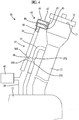
- a fuel supply device 10 in Example 1 is provided with a fuel tank 11, an inlet pipe 12 for supplying fuel to the fuel tank 11, a fuel cap 14 that opens and closes an oil supply port 13 of the inlet pipe 12, and a valve module 18.
- a lower end portion of the inlet pipe 12 (downstream side end of oil supply path) is connected to the fuel tank 11 such that the lower end portion communicates with the fuel tank 11.
- the oil supply port 13 is air-tightly closed.
- a cylindrical attachment portion 15 for attaching the valve module 18 to the inlet pipe 12 is formed to protrude on an outer circumference of an upstream side end portion (position near oil supply port 13) of the inlet pipe 12.
- the internal space of the cylindrical attachment portion 15 communicates with the inside of the inlet pipe 12 (fuel inflow path).
- a plurality of elastic locking pieces 16 disposed to surround the cylindrical attachment portion 15 is formed to protrude on an outer circumference of the inlet pipe 12.
- An area from the cylindrical attachment portion 15 of the inlet pipe 12 to the fuel tank 11 constitutes an air flow path 17 for causing air in the atmosphere to flow into the fuel tank 11 in a case where the pressure in the fuel tank 11 becomes a negative pressure (becomes lower than atmospheric pressure).
- the valve module 18 is obtained by accommodating a normally closed negative pressure valve 23 and an air filter 30 in a housing 19 and integrating the negative pressure valve 23 and the air filter 30 with each other.
- the housing 19 is obtained by assembling and combining a plurality of members.
- a cylindrical fitting portion 20 is formed on a side surface of the housing 19.
- a seal ring 21 is mounted onto an inner circumference of the cylindrical fitting portion 20.
- a stepped locking portion 22 is formed on an outer circumference of the cylindrical fitting portion 20.
- the valve module 18 is attached to the outer circumference of an upper end portion of the inlet pipe 12 when the cylindrical fitting portion 20 is externally fitted onto the cylindrical attachment portion 15 and the elastic locking pieces 16 are engaged with the locking portion 22.
- a primary chamber 24 and a secondary chamber 25 that constitute the negative pressure valve 23 are provided in the housing 19.
- the primary chamber 24 and the secondary chamber 25 constitute the air flow path 17 along with the inlet pipe 12.
- An introducing port 26 through which the primary chamber 24 and the atmosphere communicate with each other is formed in a lower end portion of the primary chamber 24 (upstream side end of air flow path 17).
- the secondary chamber 25 is disposed to be horizontally adjacent to an upper end portion of the primary chamber 24 and communicates with the internal space of the cylindrical fitting portion 20.
- a partition wall that separates the secondary chamber 25 and the primary chamber 24 from each other is formed with a valve port 27 that penetrates the partition wall.
- a valve body 28 for opening and closing the valve port 27 and a spring member 29 that urges the valve body 28 in a valve closing direction are accommodated.
- the secondary chamber 25 communicates with the inlet pipe 12 (air flow path 17) via the cylindrical fitting portion 20 and the cylindrical attachment portion 15.
- valve body 28 air-tightly closes the valve port 27 due to an urging force of the spring member 29 so that the negative pressure valve 23 is maintained in a closed state in which the primary chamber 24 and the secondary chamber 25 are air-tightly isolated from each other.
- the valve body 28 moves against the urging force of the spring member 29 in a direction such that the valve port 27 is opened. Therefore, the primary chamber 24 and the secondary chamber 25 communicate with each other and the negative pressure valve 23 enters an opened state.
- the negative pressure valve 23 Since dust floats in the atmosphere (air), when the negative pressure valve 23 is opened, the dust flows into the primary chamber 24 along with the air. In a case where the dust adheres to the valve port 27 or the valve body 28 of the negative pressure valve 23, the negative pressure valve 23 may not be fully closed because the dust is caught between an opening edge of the valve port 27 and the valve body 28 when the negative pressure valve 23 is closed.
- the primary chamber 24 in the fuel supply device 10 according to Example 1 is vertically partitioned by the bellows-shaped air filter 30.
- the air filter 30 allows the atmospheric air (air) to pass through the air filter 30 while the air filter 30 inhibits the dust in the atmosphere from passing through the air filter 30.
- a space below the air filter 30 in the primary chamber 24 space that is upstream of air filter 30 in air flow path 17 is an introducing chamber 31 that is open to the atmosphere at the introducing port 26.
- a space above the air filter 30 in the primary chamber 24 space that is downstream of air filter 30 in air flow path 17 is a clean chamber 32 that can communicate with the secondary chamber 25 via the valve port 27.
- the dust in the air is captured by the air filter 30 during a process in which the pressure in the fuel tank 11 becomes a negative pressure, the negative pressure valve 23 is opened, and air flowing into the introducing chamber 31 (primary chamber 24) via the introducing port 26 passes through the air filter 30. Therefore, clean air mixed with substantially no dust flows into the clean chamber 32. Accordingly, there is no possibility that the dust is caught between the opening edge of the valve port 27 and the valve body 28 when the negative pressure valve 23 is closed.
- the fuel supply device 10 includes the inlet pipe 12 configured such that a first end of the inlet pipe 12 is connected to the oil supply port 13 and a second end of the inlet pipe 12 is connected to the fuel tank 11 and the air flow path 17 configured such that an upstream side end of the air flow path 17 is open to the outside and a downstream side end of the air flow path 17 is connected to the fuel tank 11.
- the air flow path 17 includes the negative pressure valve 23 configured such that the valve body is moved and the valve port is opened when the pressure in the fuel tank 11 becomes a negative pressure and the air filter 30 disposed upstream of the valve port 27 (secondary chamber 25) of the negative pressure valve 23.
- the negative pressure valve 23 and the air filter 30 are integrated with each other via the housing 19 and constitute the valve module 18.
- the valve module 18 is detachable from the inlet pipe 12 that constitutes the air flow path 17. Therefore, at the time of maintenance of the air filter 30 or the negative pressure valve 23, it is possible to detach the valve module 18 from the inlet pipe 12 by elastically deforming the elastic locking pieces 16 and releasing the elastic locking pieces 16 from the locking portion 22. Since the housing 19 is obtained by assembling and combining a plurality of members, the air filter 30 or the negative pressure valve 23 can be detached when the housing 19 is disassembled. Therefore, the workability at the time of maintenance is favorable.
- Example 2 which is a specific example of the aspect of the invention will be described with reference to FIG. 3 .
- directions in FIG. 3 will be referred to as upward and downward directions in the following description.
- directions in FIG. 3 will be referred to as rightward and leftward directions.
- a fuel supply device 33 in Example 2 is obtained by making the configuration of an air flow path 35 different from that in Example 1. Since the other components are the same as those in Example 1, the same components are given the same reference numerals and description of configurations, operations, and effects thereof will be omitted.
- the fuel supply device 33 in Example 2 is provided with the fuel tank 11, the inlet pipe 12 for supplying fuel to the fuel tank 11, the fuel cap 14 that opens and closes the oil supply port 13 of the inlet pipe 12, a breather pipe 34 through which air in the fuel tank 11 is discharged to the outside while oil is being supplied, and the valve module 18.
- a lower end portion of the inlet pipe 12 (downstream side end of oil supply path) is connected to the fuel tank 11 such that the lower end portion communicates with the fuel tank 11.
- the oil supply port 13 is air-tightly closed.
- An upper end portion of the breather pipe 34 is connected to a portion of the inlet pipe 12 that is positioned slightly below the oil supply port 13 (positioned downstream of oil supply port 13 in oil supply path) such that the upper end portion communicates with the inlet pipe 12.
- the lower end portion of the breather pipe 34 is connected to the fuel tank 11 such that the lower end portion communicates with the fuel tank 11.
- the cylindrical attachment portion 15 (not shown in FIG. 3 ) for attaching the valve module 18 to the breather pipe 34 is formed to protrude on an outer circumference of the breather pipe 34.
- the internal space of the cylindrical attachment portion 15 communicates with the inside of the breather pipe 34.
- the elastic locking pieces 16 disposed to surround the cylindrical attachment portion 15 is formed to protrude on the outer circumference of the breather pipe 34.
- An area from the cylindrical attachment portion 15 of the breather pipe 34 to the fuel tank 11 constitutes the air flow path 35 for causing air in the atmosphere to flow into the fuel tank 11 in a case where the pressure in the fuel tank 11 becomes a negative pressure (becomes lower than atmospheric pressure).
- the configuration and the operation effect of the valve module 18 are the same as those in Example 1. In the following description, the valve module 18 will be given the reference numeral in the document.
- the dust in the air is captured by the air filter 30 during a process in which the pressure in the fuel tank 11 becomes a negative pressure, the negative pressure valve 23 is opened, and air flowing into the introducing chamber 31 (primary chamber 24) via the introducing port 26 passes through the air filter 30. Therefore, clean air mixed with substantially no dust flows into the clean chamber 32. Accordingly, there is no possibility that the dust is caught between the opening edge of the valve port 27 and the valve body 28 when the negative pressure valve 23 is closed.
- Example 3 which is a specific example of the aspect of the invention will be described with reference to FIGS. 4 and 5 .
- directions in FIGS. 4 and 5 will be referred to as upward and downward directions in the following description.
- directions in FIGS. 4 and 5 will be referred to as rightward and leftward directions.
- a fuel supply device 36 in Example 3 is provided with the fuel tank 11, the inlet pipe 12 for supplying fuel to the fuel tank 11, the fuel cap 14 that opens and closes the oil supply port 13 of the inlet pipe 12, a breather pipe 37 through which air in the fuel tank 11 is discharged to the outside while oil is being supplied, a canister pipe 38, a filter unit 41, and a valve unit 48.
- the oil supply port 13 is air-tightly closed.
- a lower end portion of the inlet pipe 12 (downstream side end of oil supply path) is connected to the fuel tank 11 such that the lower end portion communicates with the fuel tank 11.
- An upper end portion of the breather pipe 37 is connected to a portion of the inlet pipe 12 that is positioned slightly below the oil supply port 13 (positioned downstream of oil supply port 13 in oil supply path) such that the upper end portion communicates with the inlet pipe 12.
- the lower end portion of the breather pipe 37 is connected to the fuel tank 11 such that the lower end portion communicates with the fuel tank 11.
- a canister 40 is provided in the middle of the canister pipe 38 and a lower end portion of the canister pipe 38 is connected to the fuel tank 11. Fuel vapor that is generated in the fuel tank 11 while oil is being supplied is adsorbed by activated carbon in the canister 40 so that clean air is discharged to the atmosphere through the canister pipe 38 and the filter unit 41. When the fuel vapor adsorbed in the canister 40 is released through a negative-pressure purging process of an engine (not shown), the pressure in the canister 40 becomes a negative pressure so that the outside air is taken into the canister 40 through the filter unit 41 and the canister pipe 38.
- An upper end portion of the canister pipe 38 is positioned in the vicinity of the upper end portion of the inlet pipe 12.
- the upper end portion of the canister pipe 38 is formed as a communication port 39 and the filter unit 41 is attached to the communication port 39.
- the filter unit 41 is configured with a filter housing 42 and an air filter 43 that is accommodated in the filter housing 42.
- the filter housing 42 is attached to the outer circumference of the upper end portion of the inlet pipe 12 (in vicinity of oil supply port 13).
- the inside of the filter housing 42 is vertically partitioned by the air filter 43.
- the air filter 43 allows air to pass through the air filter 43 while the air filter 43 inhibits the dust in the air from passing through the air filter 43.
- a space above the air filter 43 in the filter housing 42 is an introducing chamber 45 that communicates with the atmosphere via an introducing port 44.
- a space below the air filter 43 in the filter housing 42 is a clean chamber 46 that communicates with the communication port 39 of the canister pipe 38.
- a portion of the breather pipe 37 and a portion of the canister pipe 38 are routed to be substantially parallel to each other and to be close to each other and an intermediate portion of each of the breather pipe 37 and the canister pipe 38 is divided into parts at a space where the portion of the breather pipe 37 and the portion of the canister pipe 38 are routed to be substantially parallel to each other.
- the valve unit 48 is attached to divided portions 37S of the breather pipe 37 and divided portions 38S of the canister pipe 38.
- the breather pipe 37 and the canister pipe 38 are connected to each other such that the divided portions 37S of the breather pipe 37 and the divided portions 38S of the canister pipe 38 can communicate with each other via the valve unit 48.
- the internal space of the filter unit 41, an area from the communication port 39 of the canister pipe 38 to a connection portion between the canister pipe 38 and the valve unit 48, the internal space of the valve unit 48, and an area from a communication portion between the breather pipe 37 and the valve unit 48 to a communication portion (connection portion) between the breather pipe 37 and the fuel tank 11 constitute an air flow path 47.
- the air flow path 47 is an inflow path for causing air in the atmosphere to flow into the fuel tank 11 in a case where the pressure in the fuel tank 11 becomes a negative pressure (becomes lower than atmospheric pressure).
- the valve unit 48 is obtained by accommodating a normally closed negative pressure valve 53 in a valve housing 49.
- the valve housing 49 is obtained by assembling and combining a plurality of members.
- the valve housing 49 is configured with a breather side cylindrical connection portion 50 to be connected to the breather pipe 37, a canister side cylindrical connection portion 51 to be connected to the canister pipe 38, and a cylindrical connection portion 52 through which the breather side cylindrical connection portion 50 and the canister side cylindrical connection portion 51 communicate with each other.
- the canister side cylindrical connection portion 51 constitutes the canister pipe 38 and the air flow path 47.
- the inside of the canister side cylindrical connection portion 51 functions as a primary chamber 54 of the negative pressure valve 53.
- a valve port 55 that penetrates the canister side cylindrical connection portion 51 in a direction from an inner circumference to an outer circumference of the canister side cylindrical connection portion 51 is formed in an area in the canister side cylindrical connection portion 51 that is aligned with the cylindrical connection portion 52.
- the cylindrical connection portion 52 is integrally formed with the breather side cylindrical connection portion 50 and protrudes toward the canister side cylindrical connection portion 51 from an outer circumference of the breather side cylindrical connection portion 50.
- a protruding end portion of the cylindrical connection portion 52 is air-tightly fixed to the outer circumference of the canister side cylindrical connection portion 51.
- the internal space of the cylindrical connection portion 52 communicates with the breather side cylindrical connection portion 50 and functions as a secondary chamber 56 of the negative pressure valve 53.
- the secondary chamber 56 constitutes the air flow path 47.
- a valve body 57 for opening and closing the valve port 55 and a spring member 58 that urges the valve body 57 in a valve closing direction are accommodated.
- valve body 57 air-tightly closes the valve port 55 due to an urging force of the spring member 58 so that the negative pressure valve 53 is maintained in a closed state in which the primary chamber 54 and the secondary chamber 56 are air-tightly isolated from each other.
- the valve body 57 moves against the urging force of the spring member 58 in a direction such that the valve port 55 is opened. Therefore, the primary chamber 54 and the secondary chamber 56 communicate with each other and the negative pressure valve 53 enters an opened state.
- the fuel supply device 36 includes the inlet pipe 12 configured such that the first end of the inlet pipe 12 is connected to an oil supply port 13 and the second end of the inlet pipe 12 is connected to the fuel tank 11 and the air flow path 47 configured such that an upstream side end of the air flow path 47 is open to the outside and a downstream side end of the air flow path 47 is connected to the fuel tank 11.
- the air flow path 47 includes the negative pressure valve 53 configured such that the valve body is moved and the valve port is opened when the pressure in the fuel tank 11 becomes a negative pressure and the air filter 43 disposed upstream of the valve port 55 (secondary chamber 56) of the negative pressure valve 53.
- the fuel supply device 36 includes the breather pipe 37 that is configured to connect a portion of the inlet pipe 12 that is downstream of the oil supply port 13 and is in the vicinity of the oil supply port 13 and the fuel tank 11 to each other and the canister pipe 38 that is disposed to be parallel to the breather pipe 37 and is configured such that a first end of the canister pipe 38 is open to the outside and a second end of the canister pipe 38 is connected to the canister 40.
- the valve unit 48 provided with the negative pressure valve 53 is provided such that the valve unit 48 connects the breather pipe 37 and the canister pipe 38 to each other.
- the breather pipe 37 and the canister pipe 38 are integrated with each other via the negative pressure valve 53 (valve unit 48). Therefore, vibration of the breather pipe 37 and the canister pipe 38 during traveling is further suppressed.
- Example 4 which is a specific example of the aspect of the invention will be described with reference to FIGS. 6 and 7 .
- directions in FIG. 6 will be referred to as upward and downward directions in the following description.
- a fuel supply device 59 in Example 4 is provided with the fuel tank 11, the inlet pipe 12 for supplying fuel to the fuel tank 11, the fuel cap 14 that opens and closes the oil supply port 13 of the inlet pipe 12, a breather pipe 60 through which air in the fuel tank 11 is discharged to the outside while oil is being supplied, a canister pipe 61, and a valve module 64.
- the oil supply port 13 is air-tightly closed.
- a lower end portion of the inlet pipe 12 (downstream side end of oil supply path) is connected to the fuel tank 11 such that the lower end portion communicates with the fuel tank 11.
- An upper end portion of the breather pipe 60 is connected to a portion of the inlet pipe 12 that is positioned slightly below the oil supply port 13 (positioned downstream of oil supply port 13 in oil supply path) such that the upper end portion communicates with the inlet pipe 12.
- the lower end portion of the breather pipe 60 is connected to the fuel tank 11 such that the lower end portion communicates with the fuel tank 11.
- the valve module 64 is attached to the breather pipe 60.
- the valve module 64 and an area from the valve module 64 of the breather pipe 60 to the fuel tank 11 constitute an air flow path 63 for causing air in the atmosphere to flow into the fuel tank 11 in a case where the pressure in the fuel tank 11 becomes a negative pressure (becomes lower than atmospheric pressure).
- An upper end portion of the canister pipe 61 is connected to a lower surface of the valve module 64.
- the valve module 64 is configured to include a housing 65, a normally closed negative pressure valve 70, an air filter 78, and an attachment member 81.
- the negative pressure valve 70 and the air filter 78 are integrated with the housing 65.
- the housing 65 is configured to include a primary side casing 66 in which a primary chamber 67 of the negative pressure valve 70 is formed and a secondary side casing 68 in which a secondary chamber 69 of the negative pressure valve 70 is formed.
- the shape of the primary side casing 66 as seen in a plan view is an approximate semi-arc shape.
- the radius of curvature of an inner circumference of the approximate semi-arc shape is equal to the outer diameter of the breather pipe 60.
- the secondary side casing 68 protrudes from an inner circumference of the primary side casing 66.
- the housing 65 is fixed to the breather pipe 60 by means of the plate-shaped attachment member 81 that has an approximate semi-arc shape as seen in a plan view.
- the primary side casing 66 and the attachment member 81 are in close-contact with an outer circumference of the breather pipe 60 and the breather pipe 60 is interposed between the primary side casing 66 and the attachment member 81 in a radial direction.
- opposite end portions of the primary side casing 66 and the attachment member 81 in a circumferential direction are fixed to each other by a fastening member (not shown) such as a bolt and a nut.
- the secondary side casing 68 is air-tightly fitted into an attachment hole 82 that is formed in the breather pipe 60 such that the attachment hole 82 penetrates the breather pipe 60 and the secondary side casing 68 faces the inside of the breather pipe 60.
- the primary chamber 67 and the secondary chamber 69 constitute the air flow path 63 along with the breather pipe 60.
- An introducing port 71 that penetrates a first circumferential end portion of an outer circumferential wall portion of the primary side casing 66 such that the primary chamber 67 communicates with the atmosphere is formed in the primary side casing 66.
- a communication port 72 and a water drain port 74 are formed in a second circumferential end portion of a lower wall portion of the primary side casing 66 such that the communication port 72 and the water drain port 74 penetrate the second circumferential end portion.
- a retaining wall portion 73 that protrudes toward the primary chamber 67 side (upper side) is formed over the entire circumference of an opening edge of the communication port 72.
- An upper end portion of the canister pipe 61 is air-tightly connected to the communication port 72.
- a canister 62 is provided in the middle of the canister pipe 61.
- a lower end portion of the canister pipe 61 is connected to the fuel tank 11. Fuel vapor that is generated in the fuel tank 11 while oil is being supplied is adsorbed by activated carbon in the canister 62 so that clean air is discharged to the atmosphere through the canister pipe 61 and the introducing port 71 of the valve module 64.
- the pressure in the canister 62 becomes a negative pressure so that the outside air is taken into the canister 62 via the introducing port 71 after passing through the valve module 64 and the canister pipe 61.
- a valve port 75 for causing the primary chamber 67 and the secondary chamber 69 to communicate with each other is formed in an inner circumferential wall portion of the primary side casing 66.
- a valve body 76 for opening and closing the valve port 75 and a spring member 77 that urges the valve body 76 in a valve closing direction are accommodated in the secondary chamber 69.
- the secondary chamber 69 communicates with the breather pipe 60.
- the valve body 76 air-tightly closes the valve port 75 due to an urging force of the spring member 77 so that the negative pressure valve 70 is maintained in a closed state in which the primary chamber 67 and the secondary chamber 69 are air-tightly isolated from each other.
- the negative pressure valve 70 Since dust floats in the atmosphere (air), when the negative pressure valve 70 is opened, the dust flows into the primary chamber 67 along with the air. In a case where the dust adheres to the valve port 75 or the valve body 76 of the negative pressure valve 70, the negative pressure valve 70 may not be fully closed because the dust is caught between an opening edge of the valve port 75 and the valve body 76 when the negative pressure valve 70 is closed.
- the primary chamber 67 in the fuel supply device 59 according to Example 4 is partitioned into an inner circumferential space and an outer circumferential space by the bellows-shaped air filter 78 that is disposed in the circumferential direction.
- the air filter 78 allows the atmospheric air (air) to pass through the air filter 78 while the air filter 78 inhibits the dust in the atmosphere from passing through the air filter 78.
- a space in the primary chamber 67 that is positioned radially outward of the air filter 78 space that is upstream of air filter 78 in air flow path 63) is an introducing chamber 79 that is open to the atmosphere at the introducing port 71.
- a space in the primary chamber 67 that is positioned radially inward of the air filter 78 space that is downstream of air filter 78 in air flow path 63
- is a clean chamber 80 that can communicate with the secondary chamber 69 via the valve port 75.
- the dust in the air is captured by the air filter 78 during a process in which the pressure in the fuel tank 11 becomes a negative pressure, the negative pressure valve 70 is opened, and air flowing into the introducing chamber 79 (primary chamber 67) via the introducing port 71 passes through the air filter 78. Therefore, clean air mixed with substantially no dust flows into the clean chamber 80. Accordingly, there is no possibility that the dust is caught between the opening edge of the valve port 75 and the valve body 76 when the negative pressure valve 70 is closed.
- the fuel supply device 59 according to Example 4 includes the inlet pipe 12 configured such that a first end of the inlet pipe 12 is connected to the oil supply port 13 and a second end of the inlet pipe 12 is connected to the fuel tank 11 and the air flow path 63 configured such that an upstream side end of the air flow path 63 is open to the outside and a downstream side end of the air flow path 63 is connected to the fuel tank 11.
- the air flow path 63 includes the negative pressure valve 70 configured such that the valve body is moved and the valve port is opened when the pressure in the fuel tank 11 becomes a negative pressure and the air filter 78 disposed upstream of the valve port 75 (secondary chamber 69) of the negative pressure valve 70.
- the negative pressure valve 70 and the air filter 78 are integrated with each other via the housing 65 and constitute the valve module 64.
- the valve module 64 is detachable from the breather pipe 60 that constitutes the air flow path 63. Therefore, at the time of maintenance of the air filter 78 or the negative pressure valve 70, it is possible to detach the housing 65 of the valve module 64 from the breather pipe 60 by loosening the fastening member. Since the housing 65 is obtained by assembling and combining a plurality of members, the air filter 78 or the negative pressure valve 70 can be detached when the housing 65 is disassembled. Therefore, the workability at the time of maintenance is favorable.
- the negative pressure valve 70 is provided such that air flows into a space positioned radially inward of the breather pipe 60 from a space positioned radially outward of the breather pipe 60 (primary chamber 67) via the secondary chamber 69.
- the air filter 78 is disposed in an approximate arc shape to cover the outer circumference of the breather pipe 60 and the negative pressure valve 70. In the case of the above-described configuration, it is possible to achieve space-saving in comparison with a case where the negative pressure valve 70 and the air filter 78 are provided to protrude in the radial direction from the outer circumference of the breather pipe 60.
- Example 5 which is a specific example of the aspect of the invention will be described with reference to FIGS. 8 and 9 .
- directions in FIG. 8 will be referred to as upward and downward directions in the following description.
- a fuel supply device 83 in Example 5 is provided with the fuel tank 11, the inlet pipe 12 for supplying fuel to the fuel tank 11, the fuel cap 14 that opens and closes the oil supply port 13 of the inlet pipe 12, the breather pipe 60 through which air in the fuel tank 11 is discharged to the outside while oil is being supplied, the canister pipe 61, and the valve module 64.
- the oil supply port 13 is air-tightly closed.
- a lower end portion of the inlet pipe 12 (downstream side end of oil supply path) is connected to the fuel tank 11 such that the lower end portion communicates with the fuel tank 11.
- An upper end portion of the breather pipe 60 is connected to a portion of the inlet pipe 12 that is positioned slightly below the oil supply port 13 (positioned downstream of oil supply port 13 in oil supply path) such that the upper end portion communicates with the inlet pipe 12.
- the lower end portion of the breather pipe 60 is connected to the fuel tank 11 such that the lower end portion communicates with the fuel tank 11.
- Example 4 the valve module 64 is attached to the breather pipe 60. However, in Example 5, the valve module 64 having the same configuration as that in Example 4 is attached to the inlet pipe 12. An upper end portion of the canister pipe 61 is connected to a lower surface of the valve module 64.
- the valve module 64 and an area from the valve module 64 of the inlet pipe 12 to the fuel tank 11 constitute an air flow path 84 for causing air in the atmosphere to flow into the fuel tank 11 in a case where the pressure in the fuel tank 11 becomes a negative pressure (becomes lower than atmospheric pressure).
- the valve module 64 is configured to include the housing 65, the normally closed negative pressure valve 70, the air filter 78, and the attachment member 81.
- the negative pressure valve 70 and the air filter 78 are integrated with the housing 65.
- the housing 65 is configured to include the primary side casing 66 in which the primary chamber 67 of the negative pressure valve 70 is formed and the secondary side casing 68 in which the secondary chamber 69 of the negative pressure valve 70 is formed.
- the shape of the primary side casing 66 as seen in a plan view is an approximate semi-arc shape.
- the radius of curvature of an inner circumference of the approximate semi-arc shape is equal to the outer diameter of the inlet pipe 12.
- the secondary side casing 68 protrudes from the inner circumference of the primary side casing 66.
- the housing 65 is fixed to the inlet pipe 12 by means of the plate-shaped attachment member 81 that has an approximate semi-arc shape as seen in a plan view.
- the primary side casing 66 and the attachment member 81 are in close-contact with the outer circumference of the inlet pipe 12 and the inlet pipe 12 is interposed between the primary side casing 66 and the attachment member 81 in the radial direction.
- opposite end portions of the primary side casing 66 and the attachment member 81 in the circumferential direction are fixed to each other by a fastening member (not shown) such as a bolt and a nut.
- the secondary side casing 68 is air-tightly fitted into the attachment hole 82 that is formed in the inlet pipe 12 such that the attachment hole 82 penetrates the inlet pipe 12 and the secondary side casing 68 faces the inside of the inlet pipe 12.
- the primary chamber 67 and the secondary chamber 69 constitute the air flow path 84 along with the inlet pipe 12.
- the introducing port 71 that penetrates the first circumferential end portion of the outer circumferential wall portion of the primary side casing 66 such that the primary chamber 67 communicates with the atmosphere is formed in the primary side casing 66.
- the communication port 72 and the water drain port 74 are formed in the second circumferential end portion of the lower wall portion of the primary side casing 66 such that the communication port 72 and the water drain port 74 penetrate the second circumferential end portion.
- the retaining wall portion 73 that protrudes toward the primary chamber 67 side (upper side) is formed over the entire circumference of the opening edge of the communication port 72.
- the upper end portion of the canister pipe 61 is air-tightly connected to the communication port 72.
- the canister 62 is provided in the middle of the canister pipe 61.
- the lower end portion of the canister pipe 61 is connected to the fuel tank 11. Fuel vapor that is generated in the fuel tank 11 while oil is being supplied is adsorbed by activated carbon in the canister 62 so that clean air is discharged to the atmosphere through the canister pipe 61 and the introducing port 71 of the valve module 64.
- the pressure in the canister 62 becomes a negative pressure so that the outside air is taken into the canister 62 via the introducing port 71 after passing through the valve module 64 and the canister pipe 61.
- the valve port 75 for causing the primary chamber 67 and the secondary chamber 69 to communicate with each other is formed in the inner circumferential wall portion of the primary side casing 66.
- the valve body 76 for opening and closing the valve port 75 and the spring member 77 that urges the valve body 76 in the valve closing direction are accommodated.
- the secondary chamber 69 communicates with the inlet pipe 12. In a usual state, the valve body 76 air-tightly closes the valve port 75 due to an urging force of the spring member 77 so that the negative pressure valve 70 is maintained in a closed state in which the primary chamber 67 and the secondary chamber 69 are air-tightly isolated from each other.
- the negative pressure valve 70 Since dust floats in the atmosphere (air), when the negative pressure valve 70 is opened, the dust flows into the primary chamber 67 along with the air. In a case where the dust adheres to the valve port 75 or the valve body 76 of the negative pressure valve 70, the negative pressure valve 70 may not be fully closed because the dust is caught between an opening edge of the valve port 75 and the valve body 76 when the negative pressure valve 70 is closed.
- the primary chamber 67 in the fuel supply device 83 according to Example 5 is partitioned into an inner circumferential space and an outer circumferential space by the bellows-shaped air filter 78 that is disposed in the circumferential direction.
- the air filter 78 allows the atmospheric air (air) to pass through the air filter 78 while the air filter 78 inhibits the dust in the atmosphere from passing through the air filter 78.
- a space in the primary chamber 67 that is positioned radially outward of the air filter 78 space that is upstream of air filter 78 in air flow path 84) is the introducing chamber 79 that is open to the atmosphere at the introducing port 71.
- a space in the primary chamber 67 that is positioned radially inward of the air filter 78 space that is downstream of air filter 78 in air flow path 84) is the clean chamber 80 that can communicate with the secondary chamber 69 via the valve port 75.
- the dust in the air is captured by the air filter 78 during a process in which the pressure in the fuel tank 11 becomes a negative pressure, the negative pressure valve 70 is opened, and air flowing into the introducing chamber 79 (primary chamber 67) via the introducing port 71 passes through the air filter 78. Therefore, clean air mixed with substantially no dust flows into the clean chamber 80. Accordingly, there is no possibility that the dust is caught between the opening edge of the valve port 75 and the valve body 76 when the negative pressure valve 70 is closed.
- the fuel supply device 83 includes the inlet pipe 12 configured such that a first end of the inlet pipe 12 is connected to the oil supply port 13 and a second end of the inlet pipe 12 is connected to the fuel tank 11 and the air flow path 84 configured such that an upstream side end of the air flow path 84 is open to the outside and a downstream side end of the air flow path 84 is connected to the fuel tank 11.
- the air flow path 84 includes the negative pressure valve 70 configured such that the valve body is moved and the valve port is opened when the pressure in the fuel tank 11 becomes a negative pressure and the air filter 78 disposed upstream of the valve port 75 (secondary chamber 69) of the negative pressure valve 70.
- the negative pressure valve 70 and the air filter 78 are integrated with each other via the housing 65 and constitute the valve module 64.
- the valve module 64 is detachable from the inlet pipe 12 that constitutes the air flow path 84. Therefore, at the time of maintenance of the air filter 78 or the negative pressure valve 70, it is possible to detach the housing 65 of the valve module 64 from the inlet pipe 12 by loosening the fastening member. Since the housing 65 is obtained by assembling and combining a plurality of members, the air filter 78 or the negative pressure valve 70 can be detached when the housing 65 is disassembled. Therefore, the workability at the time of maintenance is favorable.
- the negative pressure valve 70 is provided such that air flows into a space positioned radially inward of the inlet pipe 12 from a space positioned radially outward of the inlet pipe 12 (primary chamber 67) via the secondary chamber 69.
- the air filter 78 is disposed in an approximate arc shape to cover the outer circumference of the inlet pipe 12 and the negative pressure valve 70. In the case of the above-described configuration, it is possible to achieve space-saving in comparison with a case where the negative pressure valve 70 and the air filter 78 are provided to protrude in the radial direction from the outer circumference of the inlet pipe 12.
- Example 6 which is a specific example of the aspect of the invention will be described with reference to FIGS. 10 and 11 .
- directions in FIGS. 10 and 11 will be referred to as upward and downward directions in the following description.
- directions in FIGS. 10 and 11 will be referred to as rightward and leftward directions.
- a fuel supply device 85 in Example 6 is provided with the fuel tank 11, the inlet pipe 12 for supplying fuel to the fuel tank 11, the fuel cap 14 that opens and closes the oil supply port 13 of the inlet pipe 12, a normally closed negative pressure valve 86, and a filter unit 100.
- a lower end portion of the inlet pipe 12 (downstream side end of oil supply path) is connected to the fuel tank 11 such that the lower end portion communicates with the fuel tank 11. In a state where the fuel cap 14 is attached to the inlet pipe 12, the oil supply port 13 is air-tightly closed.
- the cylindrical portion 87 constitutes the negative pressure valve 86.
- a first seal ring 88 that air-tightly seals a gap between the cylindrical portion 87 and a valve cap 91 (which will be described later) is mounted onto a protruding end surface (left end surface) of the cylindrical portion 87.
- An engagement projection 89 is formed over the entire outer circumference of a protruding end portion of the cylindrical portion 87.
- the internal space of the cylindrical portion 87 is a secondary chamber 90 that communicates with the inside of the inlet pipe 12 (fuel inflow path).
- the valve cap 91 constituting the negative pressure valve 86 is attached to the protruding end portion of the cylindrical portion 87.
- the valve cap 91 is a single component that includes an annular plate-shaped main body portion 92, a cylindrical fitting portion 93, and a plurality of elastic engagement pieces 94.
- An outer circumferential edge portion of the plate-shaped main body portion 92 functions as a flange-shaped locking portion 95.
- the cylindrical fitting portion 93 protrudes leftward from a hole edge of a central hole of the plate-shaped main body portion 92 such that the cylindrical fitting portion 93 becomes coaxial with the cylindrical portion 87.
- the central hole of the plate-shaped main body portion 92 and the internal space of the cylindrical fitting portion 93 function as a valve port 96 of the negative pressure valve 86.
- the elastic engagement pieces 94 protrude toward a side opposite to the cylindrical fitting portion 93 side (rightward) from the plate-shaped main body portion 92 in a cantilevered state and are disposed at intervals in the circumferential direction on a circumference coaxial with the valve port 96.
- the valve cap 91 is attached to the cylindrical portion 87 with the plate-shaped main body portion 92 abutting onto the protruding end surface of the cylindrical portion 87 and the elastic engagement pieces 94 being engaged with the engagement projection 89 of the cylindrical portion 87.
- the valve cap 91 and the cylindrical portion 87 constitute a valve housing 97. It is possible to detach the valve cap 91 from the cylindrical portion 87 by elastically deforming the elastic engagement pieces 94 radially outward and releasing the elastic engagement pieces 94 from the engagement projection 89.
- the outer circumference of the inlet pipe 12 the cylindrical portion 87, and the valve cap 91 constitute the secondary chamber 90.
- a valve body 98 that opens and closes the valve port 96 and a spring member 99 that urges the valve body 98 in a valve closing direction are accommodated.
- the filter unit 100 is obtained by accommodating an air filter 110 in a filter housing 101.
- the inside of the filter housing 101 is a primary chamber 104 that constitutes the negative pressure valve 86.
- the primary chamber 104, the secondary chamber 90, and an area from a portion of the inlet pipe 12 at which the inlet pipe 12 communicates with the cylindrical portion 87 to the fuel tank 11 constitute an air flow path 105 for causing air in the atmosphere to flow into the fuel tank 11 in a case where the pressure in the fuel tank 11 becomes a negative pressure (becomes lower than atmospheric pressure).
- An introducing port 106 that penetrates an outer wall of the filter housing 101 and through which the primary chamber 104 and the atmosphere communicate with each other is formed in a lower end portion of the primary chamber 104 (upstream side end portion of air flow path 105).
- a fitting hole 107 that penetrates the outer wall of the filter housing 101 and through which the inside of the primary chamber 104 and the outside of the filter housing 101 communicate with each other is formed in an upper end portion of the primary chamber 104.
- a second seal ring 108 that air-tightly seals a gap between the filter housing 101 and the valve cap 91 is mounted onto an area on an outer surface of the filter housing 101 that coaxially surrounds the fitting hole 107.
- On the outer surface of the filter housing 101 a plurality of elastic locking pieces 109 is formed to protrude in a cantilevered state. The elastic locking pieces 109 are disposed to coaxially surround the second seal ring 108.
- the negative pressure valve 86 is configured.
- the fitting hole 107 is fitted onto the cylindrical fitting portion 93 and the area (upper end portion of right surface) on the outer surface of the filter housing 101 onto which the second seal ring 108 is mounted abuts onto the plate-shaped main body portion 92 of the valve cap 91.
- the elastic locking pieces 109 are engaged with the locking portion 95, the filter unit 100 is locked with respect to the valve housing 97 in a state of being attached. It is possible to detach the filter unit 100 from the valve housing 97 by elastically deforming the elastic locking pieces 109 radially outward and releasing the elastic locking pieces 109 from the locking portion 95.
- valve body 98 air-tightly closes the valve port 96 due to an urging force of the spring member 99 so that the negative pressure valve 86 is maintained in a closed state in which the primary chamber 104 and the secondary chamber 90 are air-tightly isolated from each other.
- the valve body 98 moves against the urging force of the spring member 99 in a direction such that the valve port 96 is opened. Therefore, the primary chamber 104 and the secondary chamber 90 communicate with each other and the negative pressure valve 86 enters an opened state.
- the negative pressure valve 86 Since dust floats in the atmosphere (air), when the negative pressure valve 86 is opened, the dust flows into the primary chamber 104 along with the air. In a case where the dust adheres to the valve port 96 or the valve body 98 of the negative pressure valve 86, the negative pressure valve 86 may not be fully closed because the dust is caught between an opening edge of the valve port 96 and the valve body 98 when the negative pressure valve 86 is closed.
- the inside of the primary chamber 104 in the fuel supply device 85 according to Example 6 is partitioned into two chambers of an introducing chamber 111 and a clean chamber 112 by the bellows-shaped air filter 110.
- the air filter 110 allows the atmospheric air (air) to pass through the air filter 110 while the air filter 110 inhibits the dust in the atmosphere from passing through the air filter 110.
- the introducing chamber 111 is open to the atmosphere at the introducing port 106.
- the clean chamber 112 communicates with the secondary chamber 90 via the valve port 96.
- the dust in the air is captured by the air filter 110 during a process in which the pressure in the fuel tank 11 becomes a negative pressure, the negative pressure valve 86 is opened, and air flowing into the introducing chamber 111 (primary chamber 104) via the introducing port 106 passes through the air filter 110. Therefore, clean air mixed with substantially no dust flows into the clean chamber 112. Accordingly, there is no possibility that the dust is caught between the opening edge of the valve port 96 and the valve body 98 when the negative pressure valve 86 is closed.
- the fuel supply device 85 includes the inlet pipe 12 configured such that a first end of the inlet pipe 12 is connected to the oil supply port 13 and a second end of the inlet pipe 12 is connected to the fuel tank 11 and the air flow path 105 configured such that an upstream side end of the air flow path 105 is open to the outside and a downstream side end of the air flow path 105 is connected to the fuel tank 11.
- the air flow path 105 includes the negative pressure valve 86 configured such that the valve body is moved and the valve port is opened when the pressure in the fuel tank 11 becomes a negative pressure and the air filter 110 disposed upstream of the valve port 96 (secondary chamber 90) of the negative pressure valve 86.
- the fuel supply device 85 includes the valve housing 97 and the filter unit 100.
- the secondary chamber 90 constituting the negative pressure valve 86 is formed in the valve housing 97 and the valve body 98 that opens and closes the valve port 96 is accommodated in the secondary chamber 90.
- the primary chamber 104 constituting the negative pressure valve 86 is formed in the filter unit 100 and the inside of the primary chamber 104 is partitioned into the introducing chamber 111 communicating with the atmosphere and the clean chamber 112 facing the valve port 96 by the air filter 110.
- the filter unit 100 is detachable from the valve housing 97.
- the valve housing 97 is configured by assembling the cylindrical portion 87 that accommodates the valve body 98 and the spring member 99 and the valve cap 91 that closes an opening portion of the cylindrical portion 87. It is possible to detach the valve cap 91 from the cylindrical portion 87 by elastically deforming the elastic engagement pieces 94 of the valve cap 91 and releasing the elastic engagement pieces 94 from the engagement projection 89 of the cylindrical portion 87. When the valve cap 91 is detached from the cylindrical portion 87, it becomes possible to clean or replace the valve body 98 and the spring member 99. Therefore, the workability at the time of maintenance of the negative pressure valve 86 is also favorable.
- the negative pressure valve 86 includes the cylindrical portion 87 that accommodates the valve body 98 and the cylindrical portion 87 integrally protrudes in the radial direction from the outer circumference (circumferential surface) of the inlet pipe 12.
- the number of components can be reduced in comparison with a case where the cylindrical portion 87 and the inlet pipe 12 are provided separately from each other.
Landscapes
- Engineering & Computer Science (AREA)
- Life Sciences & Earth Sciences (AREA)
- Sustainable Development (AREA)
- Sustainable Energy (AREA)
- Chemical & Material Sciences (AREA)
- Combustion & Propulsion (AREA)
- Transportation (AREA)
- Mechanical Engineering (AREA)
- Cooling, Air Intake And Gas Exhaust, And Fuel Tank Arrangements In Propulsion Units (AREA)
Abstract
Description
- The present invention relates to a fuel supply device.
- Japanese Unexamined Patent Application Publication No.
05-301530 JP 05-301530 A - In the case of the fuel cap, dust collected in the dust collecting recess portion may be whirled up by an air stream passing through the air flow path and the dust may adhere to a valve seat or a valve body of the negative pressure valve since the dust collecting recess portion faces the air flow path. In a case where the dust adheres to the negative pressure valve, the negative pressure valve is not fully closed because the dust is caught between the valve seat and the valve body when the negative pressure valve is closed.
- The invention provides a fuel supply device with which it is possible to achieve an improvement in reliability of a negative pressure valve.
- An aspect of the invention relates to a fuel supply device including an inlet pipe and an air flow path. A first end of the inlet pipe is configured to be connected to an oil supply port and a second end of the inlet pipe is configured to be connected to a fuel tank. An upstream side end of the air flow path is configured to be open to the outside and a downstream side end of the air flow path is configured to be connected to the fuel tank. The air flow path includes a negative pressure valve and an air filter. The negative pressure valve is configured to move a valve body to open a valve port when the pressure in the fuel tank becomes a negative pressure. The air filter is disposed upstream of the negative pressure valve.
- In the fuel supply device according to the aspect of the invention, the negative pressure valve and the air filter may be integrated with each other and may constitute a valve module that is detachable from the air flow path. In this case, the workability at the time of maintenance of the air filter or the negative pressure valve is favorable.
- The fuel supply device according to the aspect of the invention may further include a breather pipe configured to connect the inlet pipe and the fuel tank to each other, and a canister pipe, a first end of the canister pipe configured to be open to the outside and a second end of the canister pipe configured to be connected to a canister. The negative pressure valve may be configured to connect the breather pipe and the canister pipe to each other. In this case, the breather pipe and the canister pipe are integrated with each other via the negative pressure valve. Therefore, vibration of the breather pipe and the canister pipe during traveling can be further suppressed.
- In the fuel supply device according to the aspect of the invention, the negative pressure valve may be provided on an outer circumference of the inlet pipe or an outer circumference of the breather pipe, and the air filter may be disposed to cover the outer circumference of the inlet pipe and the negative pressure valve or to cover the outer circumference of the breather pipe and the negative pressure valve. In this case, it is possible to achieve space-saving in comparison with a case where the negative pressure valve and the air filter are provided to protrude in a radial direction from the outer circumference of the inlet pipe or the outer circumference of the breather pipe.
- The fuel supply device according to the aspect of the invention may further include a valve housing and a filter unit. The negative pressure valve may include a primary chamber and a secondary chamber. The secondary chamber may be formed in the valve housing and the valve body may be accommodated in the secondary chamber. The primary chamber may be formed in the filter unit and the inside of the primary chamber may be partitioned into an introducing chamber communicating with the atmosphere and a clean chamber facing the valve port by the air filter. The filter unit may be configured to be detachable from the valve housing. In this case, the workability at the time of maintenance of the air filter is favorable.
- In the fuel supply device according to the aspect of the invention, the negative pressure valve may include a cylindrical portion that accommodates the valve body and the cylindrical portion may integrally protrude in a radial direction from a circumferential surface of the inlet pipe. In this case, the number of components can be reduced in comparison with a case where the cylindrical portion and the inlet pipe are provided separately from each other.
- In the fuel supply device according to the aspect of the invention, the negative pressure valve may include a cylindrical portion that accommodates the valve body and the cylindrical portion may integrally protrude in a radial direction from a circumferential surface of the breather pipe.
- According to the aspect of the invention, air in the atmosphere flows into the fuel tank after sequentially passing through the air filter and the negative pressure valve when the negative pressure valve is opened. However, the dust in the atmosphere does not reach the negative pressure valve since the dust cannot pass through the air filter. Therefore, it is possible to prevent a malfunction of the negative pressure valve that occurs when the dust in the atmosphere is caught.
- Features, advantages, and technical and industrial significance of exemplary embodiments of the invention will be described below with reference to the accompanying drawings, in which like numerals denote like elements, and wherein:
-
FIG. 1 is a front view of a fuel supply device according to Example 1; -
FIG. 2 is a sectional front view of a valve module; -
FIG. 3 is a front view of a fuel supply device according to Example 2; -
FIG. 4 is a front view of a fuel supply device according to Example 3; -
FIG. 5 is a sectional front view of a valve module; -
FIG. 6 is a front view of a fuel supply device according to Example 4; -
FIG. 7 is a sectional plan view of a valve module; -
FIG. 8 is a front view of a fuel supply device according to Example 5; -
FIG. 9 is a sectional plan view of a valve module; -
FIG. 10 is a front view of a fuel supply device according to Example 6; and -
FIG. 11 is a sectional front view of a valve module. - Hereinafter, Example 1 which is a specific example of the aspect of the invention will be described with reference to
FIGS. 1 and2 . Regarding the vertical direction, directions inFIGS. 1 and2 will be referred to as upward and downward directions in the following description. Regarding the horizontal direction, directions inFIGS. 1 and2 will be referred to as rightward and leftward directions. - A
fuel supply device 10 in Example 1 is provided with afuel tank 11, aninlet pipe 12 for supplying fuel to thefuel tank 11, afuel cap 14 that opens and closes anoil supply port 13 of theinlet pipe 12, and avalve module 18. A lower end portion of the inlet pipe 12 (downstream side end of oil supply path) is connected to thefuel tank 11 such that the lower end portion communicates with thefuel tank 11. In a state where thefuel cap 14 is attached to theinlet pipe 12, theoil supply port 13 is air-tightly closed. - A
cylindrical attachment portion 15 for attaching thevalve module 18 to theinlet pipe 12 is formed to protrude on an outer circumference of an upstream side end portion (position near oil supply port 13) of theinlet pipe 12. The internal space of thecylindrical attachment portion 15 communicates with the inside of the inlet pipe 12 (fuel inflow path). A plurality ofelastic locking pieces 16 disposed to surround thecylindrical attachment portion 15 is formed to protrude on an outer circumference of theinlet pipe 12. - An area from the
cylindrical attachment portion 15 of theinlet pipe 12 to thefuel tank 11 constitutes anair flow path 17 for causing air in the atmosphere to flow into thefuel tank 11 in a case where the pressure in thefuel tank 11 becomes a negative pressure (becomes lower than atmospheric pressure). - The
valve module 18 is obtained by accommodating a normally closednegative pressure valve 23 and anair filter 30 in ahousing 19 and integrating thenegative pressure valve 23 and theair filter 30 with each other. Thehousing 19 is obtained by assembling and combining a plurality of members. Acylindrical fitting portion 20 is formed on a side surface of thehousing 19. Aseal ring 21 is mounted onto an inner circumference of thecylindrical fitting portion 20. A stepped lockingportion 22 is formed on an outer circumference of the cylindricalfitting portion 20. Thevalve module 18 is attached to the outer circumference of an upper end portion of theinlet pipe 12 when the cylindricalfitting portion 20 is externally fitted onto thecylindrical attachment portion 15 and theelastic locking pieces 16 are engaged with the lockingportion 22. - In the
housing 19, a primary chamber 24 and asecondary chamber 25 that constitute thenegative pressure valve 23 are provided. The primary chamber 24 and thesecondary chamber 25 constitute theair flow path 17 along with theinlet pipe 12. An introducingport 26 through which the primary chamber 24 and the atmosphere communicate with each other is formed in a lower end portion of the primary chamber 24 (upstream side end of air flow path 17). Thesecondary chamber 25 is disposed to be horizontally adjacent to an upper end portion of the primary chamber 24 and communicates with the internal space of the cylindricalfitting portion 20. - A partition wall that separates the
secondary chamber 25 and the primary chamber 24 from each other is formed with avalve port 27 that penetrates the partition wall. In thesecondary chamber 25, avalve body 28 for opening and closing thevalve port 27 and aspring member 29 that urges thevalve body 28 in a valve closing direction are accommodated. Thesecondary chamber 25 communicates with the inlet pipe 12 (air flow path 17) via the cylindricalfitting portion 20 and thecylindrical attachment portion 15. - In a usual state, the
valve body 28 air-tightly closes thevalve port 27 due to an urging force of thespring member 29 so that thenegative pressure valve 23 is maintained in a closed state in which the primary chamber 24 and thesecondary chamber 25 are air-tightly isolated from each other. When the pressure in the secondary chamber 25 (in fuel tank 11) becomes lower than the pressure in the primary chamber 24, thevalve body 28 moves against the urging force of thespring member 29 in a direction such that thevalve port 27 is opened. Therefore, the primary chamber 24 and thesecondary chamber 25 communicate with each other and thenegative pressure valve 23 enters an opened state. When thenegative pressure valve 23 enters the opened state, air in the atmosphere is introduced into the primary chamber 24 via the introducingport 26 and the air flows into thefuel tank 11 after sequentially passing through thevalve port 27, thesecondary chamber 25, the cylindricalfitting portion 20, thecylindrical attachment portion 15, and the air flow path 17 (inlet pipe 12). - Since dust floats in the atmosphere (air), when the
negative pressure valve 23 is opened, the dust flows into the primary chamber 24 along with the air. In a case where the dust adheres to thevalve port 27 or thevalve body 28 of thenegative pressure valve 23, thenegative pressure valve 23 may not be fully closed because the dust is caught between an opening edge of thevalve port 27 and thevalve body 28 when thenegative pressure valve 23 is closed. - As a countermeasure for the above-described problem, the primary chamber 24 in the
fuel supply device 10 according to Example 1 is vertically partitioned by the bellows-shapedair filter 30. Theair filter 30 allows the atmospheric air (air) to pass through theair filter 30 while theair filter 30 inhibits the dust in the atmosphere from passing through theair filter 30. A space below theair filter 30 in the primary chamber 24 (space that is upstream ofair filter 30 in air flow path 17) is an introducingchamber 31 that is open to the atmosphere at the introducingport 26. A space above theair filter 30 in the primary chamber 24 (space that is downstream ofair filter 30 in air flow path 17) is aclean chamber 32 that can communicate with thesecondary chamber 25 via thevalve port 27. - The dust in the air is captured by the
air filter 30 during a process in which the pressure in thefuel tank 11 becomes a negative pressure, thenegative pressure valve 23 is opened, and air flowing into the introducing chamber 31 (primary chamber 24) via the introducingport 26 passes through theair filter 30. Therefore, clean air mixed with substantially no dust flows into theclean chamber 32. Accordingly, there is no possibility that the dust is caught between the opening edge of thevalve port 27 and thevalve body 28 when thenegative pressure valve 23 is closed. - The
fuel supply device 10 according to Example 1 includes theinlet pipe 12 configured such that a first end of theinlet pipe 12 is connected to theoil supply port 13 and a second end of theinlet pipe 12 is connected to thefuel tank 11 and theair flow path 17 configured such that an upstream side end of theair flow path 17 is open to the outside and a downstream side end of theair flow path 17 is connected to thefuel tank 11. Theair flow path 17 includes thenegative pressure valve 23 configured such that the valve body is moved and the valve port is opened when the pressure in thefuel tank 11 becomes a negative pressure and theair filter 30 disposed upstream of the valve port 27 (secondary chamber 25) of thenegative pressure valve 23. - In the case of the above-described configuration, air in the atmosphere flows into the
fuel tank 11 after sequentially passing through theair filter 30 and thenegative pressure valve 23 when thenegative pressure valve 23 is opened. However, the dust in the atmosphere does not reach thenegative pressure valve 23 since the dust cannot pass through theair filter 30. Therefore, it is possible to prevent a malfunction of thenegative pressure valve 23 that occurs when the dust in the atmosphere is caught. - The
negative pressure valve 23 and theair filter 30 are integrated with each other via thehousing 19 and constitute thevalve module 18. Thevalve module 18 is detachable from theinlet pipe 12 that constitutes theair flow path 17. Therefore, at the time of maintenance of theair filter 30 or thenegative pressure valve 23, it is possible to detach thevalve module 18 from theinlet pipe 12 by elastically deforming theelastic locking pieces 16 and releasing theelastic locking pieces 16 from the lockingportion 22. Since thehousing 19 is obtained by assembling and combining a plurality of members, theair filter 30 or thenegative pressure valve 23 can be detached when thehousing 19 is disassembled. Therefore, the workability at the time of maintenance is favorable. - Example 2 which is a specific example of the aspect of the invention will be described with reference to
FIG. 3 . Regarding the vertical direction, directions inFIG. 3 will be referred to as upward and downward directions in the following description. Regarding the horizontal direction, directions inFIG. 3 will be referred to as rightward and leftward directions. - A
fuel supply device 33 in Example 2 is obtained by making the configuration of an air flow path 35 different from that in Example 1. Since the other components are the same as those in Example 1, the same components are given the same reference numerals and description of configurations, operations, and effects thereof will be omitted. - The
fuel supply device 33 in Example 2 is provided with thefuel tank 11, theinlet pipe 12 for supplying fuel to thefuel tank 11, thefuel cap 14 that opens and closes theoil supply port 13 of theinlet pipe 12, abreather pipe 34 through which air in thefuel tank 11 is discharged to the outside while oil is being supplied, and thevalve module 18. A lower end portion of the inlet pipe 12 (downstream side end of oil supply path) is connected to thefuel tank 11 such that the lower end portion communicates with thefuel tank 11. - In a state where the
fuel cap 14 is attached to theinlet pipe 12, theoil supply port 13 is air-tightly closed. An upper end portion of thebreather pipe 34 is connected to a portion of theinlet pipe 12 that is positioned slightly below the oil supply port 13 (positioned downstream ofoil supply port 13 in oil supply path) such that the upper end portion communicates with theinlet pipe 12. The lower end portion of thebreather pipe 34 is connected to thefuel tank 11 such that the lower end portion communicates with thefuel tank 11. - The cylindrical attachment portion 15 (not shown in
FIG. 3 ) for attaching thevalve module 18 to thebreather pipe 34 is formed to protrude on an outer circumference of thebreather pipe 34. The internal space of thecylindrical attachment portion 15 communicates with the inside of thebreather pipe 34. Theelastic locking pieces 16 disposed to surround thecylindrical attachment portion 15 is formed to protrude on the outer circumference of thebreather pipe 34. - An area from the
cylindrical attachment portion 15 of thebreather pipe 34 to thefuel tank 11 constitutes the air flow path 35 for causing air in the atmosphere to flow into thefuel tank 11 in a case where the pressure in thefuel tank 11 becomes a negative pressure (becomes lower than atmospheric pressure). The configuration and the operation effect of thevalve module 18 are the same as those in Example 1. In the following description, thevalve module 18 will be given the reference numeral in the document. - The dust in the air is captured by the
air filter 30 during a process in which the pressure in thefuel tank 11 becomes a negative pressure, thenegative pressure valve 23 is opened, and air flowing into the introducing chamber 31 (primary chamber 24) via the introducingport 26 passes through theair filter 30. Therefore, clean air mixed with substantially no dust flows into theclean chamber 32. Accordingly, there is no possibility that the dust is caught between the opening edge of thevalve port 27 and thevalve body 28 when thenegative pressure valve 23 is closed. - Example 3 which is a specific example of the aspect of the invention will be described with reference to
FIGS. 4 and5 . Regarding the vertical direction, directions inFIGS. 4 and5 will be referred to as upward and downward directions in the following description. Regarding the horizontal direction, directions inFIGS. 4 and5 will be referred to as rightward and leftward directions. - A
fuel supply device 36 in Example 3 is provided with thefuel tank 11, theinlet pipe 12 for supplying fuel to thefuel tank 11, thefuel cap 14 that opens and closes theoil supply port 13 of theinlet pipe 12, abreather pipe 37 through which air in thefuel tank 11 is discharged to the outside while oil is being supplied, acanister pipe 38, afilter unit 41, and avalve unit 48. In a state where thefuel cap 14 is attached to theinlet pipe 12, theoil supply port 13 is air-tightly closed. - A lower end portion of the inlet pipe 12 (downstream side end of oil supply path) is connected to the
fuel tank 11 such that the lower end portion communicates with thefuel tank 11. An upper end portion of thebreather pipe 37 is connected to a portion of theinlet pipe 12 that is positioned slightly below the oil supply port 13 (positioned downstream ofoil supply port 13 in oil supply path) such that the upper end portion communicates with theinlet pipe 12. The lower end portion of thebreather pipe 37 is connected to thefuel tank 11 such that the lower end portion communicates with thefuel tank 11. - A
canister 40 is provided in the middle of thecanister pipe 38 and a lower end portion of thecanister pipe 38 is connected to thefuel tank 11. Fuel vapor that is generated in thefuel tank 11 while oil is being supplied is adsorbed by activated carbon in thecanister 40 so that clean air is discharged to the atmosphere through thecanister pipe 38 and thefilter unit 41. When the fuel vapor adsorbed in thecanister 40 is released through a negative-pressure purging process of an engine (not shown), the pressure in thecanister 40 becomes a negative pressure so that the outside air is taken into thecanister 40 through thefilter unit 41 and thecanister pipe 38. - An upper end portion of the
canister pipe 38 is positioned in the vicinity of the upper end portion of theinlet pipe 12. The upper end portion of thecanister pipe 38 is formed as acommunication port 39 and thefilter unit 41 is attached to thecommunication port 39. Thefilter unit 41 is configured with afilter housing 42 and anair filter 43 that is accommodated in thefilter housing 42. Thefilter housing 42 is attached to the outer circumference of the upper end portion of the inlet pipe 12 (in vicinity of oil supply port 13). - The inside of the
filter housing 42 is vertically partitioned by theair filter 43. Theair filter 43 allows air to pass through theair filter 43 while theair filter 43 inhibits the dust in the air from passing through theair filter 43. A space above theair filter 43 in thefilter housing 42 is an introducingchamber 45 that communicates with the atmosphere via an introducingport 44. A space below theair filter 43 in thefilter housing 42 is aclean chamber 46 that communicates with thecommunication port 39 of thecanister pipe 38. - A portion of the
breather pipe 37 and a portion of thecanister pipe 38 are routed to be substantially parallel to each other and to be close to each other and an intermediate portion of each of thebreather pipe 37 and thecanister pipe 38 is divided into parts at a space where the portion of thebreather pipe 37 and the portion of thecanister pipe 38 are routed to be substantially parallel to each other. Thevalve unit 48 is attached to dividedportions 37S of thebreather pipe 37 and dividedportions 38S of thecanister pipe 38. Thebreather pipe 37 and thecanister pipe 38 are connected to each other such that the dividedportions 37S of thebreather pipe 37 and the dividedportions 38S of thecanister pipe 38 can communicate with each other via thevalve unit 48. - The internal space of the
filter unit 41, an area from thecommunication port 39 of thecanister pipe 38 to a connection portion between thecanister pipe 38 and thevalve unit 48, the internal space of thevalve unit 48, and an area from a communication portion between thebreather pipe 37 and thevalve unit 48 to a communication portion (connection portion) between thebreather pipe 37 and thefuel tank 11 constitute anair flow path 47. Theair flow path 47 is an inflow path for causing air in the atmosphere to flow into thefuel tank 11 in a case where the pressure in thefuel tank 11 becomes a negative pressure (becomes lower than atmospheric pressure). - The
valve unit 48 is obtained by accommodating a normally closednegative pressure valve 53 in avalve housing 49. Thevalve housing 49 is obtained by assembling and combining a plurality of members. Thevalve housing 49 is configured with a breather sidecylindrical connection portion 50 to be connected to thebreather pipe 37, a canister sidecylindrical connection portion 51 to be connected to thecanister pipe 38, and acylindrical connection portion 52 through which the breather sidecylindrical connection portion 50 and the canister sidecylindrical connection portion 51 communicate with each other. - Upper and lower end portions of the breather side
cylindrical connection portion 50 that protrude upward and downward from thecylindrical connection portion 52 are air-tightly fixed in a state of being internally fitted into the dividedportions 37S of thebreather pipe 37. Therefore, the dividedportions 37S of thebreather pipe 37 are connected to each other in a row via the breather sidecylindrical connection portion 50. The breather sidecylindrical connection portion 50 constitutes thebreather pipe 37 and theair flow path 47. - Upper and lower end portions of the canister side
cylindrical connection portion 51 that protrude upward and downward from thecylindrical connection portion 52 are air-tightly fixed in a state of being internally fitted into the dividedportions 38S of thecanister pipe 38. Therefore, the dividedportions 38S of thecanister pipe 38 are connected to each other in a row via the canister sidecylindrical connection portion 51. The canister sidecylindrical connection portion 51 constitutes thecanister pipe 38 and theair flow path 47. The inside of the canister sidecylindrical connection portion 51 functions as aprimary chamber 54 of thenegative pressure valve 53. Avalve port 55 that penetrates the canister sidecylindrical connection portion 51 in a direction from an inner circumference to an outer circumference of the canister sidecylindrical connection portion 51 is formed in an area in the canister sidecylindrical connection portion 51 that is aligned with thecylindrical connection portion 52. - The
cylindrical connection portion 52 is integrally formed with the breather sidecylindrical connection portion 50 and protrudes toward the canister sidecylindrical connection portion 51 from an outer circumference of the breather sidecylindrical connection portion 50. A protruding end portion of thecylindrical connection portion 52 is air-tightly fixed to the outer circumference of the canister sidecylindrical connection portion 51. The internal space of thecylindrical connection portion 52 communicates with the breather sidecylindrical connection portion 50 and functions as asecondary chamber 56 of thenegative pressure valve 53. Thesecondary chamber 56 constitutes theair flow path 47. In the secondary chamber 56 (in cylindrical connection portion 52), avalve body 57 for opening and closing thevalve port 55 and aspring member 58 that urges thevalve body 57 in a valve closing direction are accommodated. - In a usual state, the
valve body 57 air-tightly closes thevalve port 55 due to an urging force of thespring member 58 so that thenegative pressure valve 53 is maintained in a closed state in which theprimary chamber 54 and thesecondary chamber 56 are air-tightly isolated from each other. When the pressure in the secondary chamber 56 (in fuel tank 11) becomes lower than the pressure in theprimary chamber 54, thevalve body 57 moves against the urging force of thespring member 58 in a direction such that thevalve port 55 is opened. Therefore, theprimary chamber 54 and thesecondary chamber 56 communicate with each other and thenegative pressure valve 53 enters an opened state. When thenegative pressure valve 53 enters the opened state, air in the atmosphere is introduced into the introducingchamber 45 of thefilter housing 42 via the introducingport 44 and passes through theair filter 43. Then, the air flows into thefuel tank 11 after sequentially passing through theclean chamber 46, thecanister pipe 38, theprimary chamber 54, thevalve port 55, thesecondary chamber 56, and thebreather pipe 37. - Although the dust floating in the atmosphere (air) also flows into the
filter housing 42 when thenegative pressure valve 53 is opened, the dust in air is captured by theair filter 43 during a process of passing through theair filter 43. Therefore, clean air mixed with substantially no dust flows into theclean chamber 46. Accordingly, there is no possibility that the dust is caught between an opening edge of thevalve port 55 and thevalve body 57 when thenegative pressure valve 53 is closed. - The
fuel supply device 36 according to Example 3 includes theinlet pipe 12 configured such that the first end of theinlet pipe 12 is connected to anoil supply port 13 and the second end of theinlet pipe 12 is connected to thefuel tank 11 and theair flow path 47 configured such that an upstream side end of theair flow path 47 is open to the outside and a downstream side end of theair flow path 47 is connected to thefuel tank 11. Theair flow path 47 includes thenegative pressure valve 53 configured such that the valve body is moved and the valve port is opened when the pressure in thefuel tank 11 becomes a negative pressure and theair filter 43 disposed upstream of the valve port 55 (secondary chamber 56) of thenegative pressure valve 53. - In the case of the above-described configuration, air in the atmosphere flows into the
fuel tank 11 after sequentially passing through theair filter 43 and thenegative pressure valve 53 when thenegative pressure valve 53 is opened. However, the dust in the atmosphere does not reach thenegative pressure valve 53 since the dust cannot pass through theair filter 43. Therefore, it is possible to prevent a malfunction of thenegative pressure valve 53 that occurs when the dust in the atmosphere is caught. - The
fuel supply device 36 according to Example 3 includes thebreather pipe 37 that is configured to connect a portion of theinlet pipe 12 that is downstream of theoil supply port 13 and is in the vicinity of theoil supply port 13 and thefuel tank 11 to each other and thecanister pipe 38 that is disposed to be parallel to thebreather pipe 37 and is configured such that a first end of thecanister pipe 38 is open to the outside and a second end of thecanister pipe 38 is connected to thecanister 40. In addition, thevalve unit 48 provided with thenegative pressure valve 53 is provided such that thevalve unit 48 connects thebreather pipe 37 and thecanister pipe 38 to each other. In the case of the above-described configuration, thebreather pipe 37 and thecanister pipe 38 are integrated with each other via the negative pressure valve 53 (valve unit 48). Therefore, vibration of thebreather pipe 37 and thecanister pipe 38 during traveling is further suppressed. - Hereinafter, Example 4 which is a specific example of the aspect of the invention will be described with reference to
FIGS. 6 and7 . Regarding the vertical direction, directions inFIG. 6 will be referred to as upward and downward directions in the following description. - A
fuel supply device 59 in Example 4 is provided with thefuel tank 11, theinlet pipe 12 for supplying fuel to thefuel tank 11, thefuel cap 14 that opens and closes theoil supply port 13 of theinlet pipe 12, abreather pipe 60 through which air in thefuel tank 11 is discharged to the outside while oil is being supplied, acanister pipe 61, and avalve module 64. In a state where thefuel cap 14 is attached to theinlet pipe 12, theoil supply port 13 is air-tightly closed. - A lower end portion of the inlet pipe 12 (downstream side end of oil supply path) is connected to the
fuel tank 11 such that the lower end portion communicates with thefuel tank 11. An upper end portion of thebreather pipe 60 is connected to a portion of theinlet pipe 12 that is positioned slightly below the oil supply port 13 (positioned downstream ofoil supply port 13 in oil supply path) such that the upper end portion communicates with theinlet pipe 12. The lower end portion of thebreather pipe 60 is connected to thefuel tank 11 such that the lower end portion communicates with thefuel tank 11. - The
valve module 64 is attached to thebreather pipe 60. Thevalve module 64 and an area from thevalve module 64 of thebreather pipe 60 to thefuel tank 11 constitute anair flow path 63 for causing air in the atmosphere to flow into thefuel tank 11 in a case where the pressure in thefuel tank 11 becomes a negative pressure (becomes lower than atmospheric pressure). An upper end portion of thecanister pipe 61 is connected to a lower surface of thevalve module 64. - The
valve module 64 is configured to include ahousing 65, a normally closednegative pressure valve 70, anair filter 78, and anattachment member 81. Thenegative pressure valve 70 and theair filter 78 are integrated with thehousing 65. Thehousing 65 is configured to include aprimary side casing 66 in which aprimary chamber 67 of thenegative pressure valve 70 is formed and asecondary side casing 68 in which asecondary chamber 69 of thenegative pressure valve 70 is formed. The shape of theprimary side casing 66 as seen in a plan view is an approximate semi-arc shape. The radius of curvature of an inner circumference of the approximate semi-arc shape is equal to the outer diameter of thebreather pipe 60. Thesecondary side casing 68 protrudes from an inner circumference of theprimary side casing 66. - The
housing 65 is fixed to thebreather pipe 60 by means of the plate-shapedattachment member 81 that has an approximate semi-arc shape as seen in a plan view. In a state where thehousing 65 is fixed to thebreather pipe 60, theprimary side casing 66 and theattachment member 81 are in close-contact with an outer circumference of thebreather pipe 60 and thebreather pipe 60 is interposed between theprimary side casing 66 and theattachment member 81 in a radial direction. In addition, opposite end portions of theprimary side casing 66 and theattachment member 81 in a circumferential direction are fixed to each other by a fastening member (not shown) such as a bolt and a nut. Thesecondary side casing 68 is air-tightly fitted into anattachment hole 82 that is formed in thebreather pipe 60 such that theattachment hole 82 penetrates thebreather pipe 60 and thesecondary side casing 68 faces the inside of thebreather pipe 60. - The
primary chamber 67 and thesecondary chamber 69 constitute theair flow path 63 along with thebreather pipe 60. An introducingport 71 that penetrates a first circumferential end portion of an outer circumferential wall portion of theprimary side casing 66 such that theprimary chamber 67 communicates with the atmosphere is formed in theprimary side casing 66. Acommunication port 72 and awater drain port 74 are formed in a second circumferential end portion of a lower wall portion of theprimary side casing 66 such that thecommunication port 72 and thewater drain port 74 penetrate the second circumferential end portion. A retainingwall portion 73 that protrudes toward theprimary chamber 67 side (upper side) is formed over the entire circumference of an opening edge of thecommunication port 72. - An upper end portion of the
canister pipe 61 is air-tightly connected to thecommunication port 72. Acanister 62 is provided in the middle of thecanister pipe 61. A lower end portion of thecanister pipe 61 is connected to thefuel tank 11. Fuel vapor that is generated in thefuel tank 11 while oil is being supplied is adsorbed by activated carbon in thecanister 62 so that clean air is discharged to the atmosphere through thecanister pipe 61 and the introducingport 71 of thevalve module 64. When the fuel vapor adsorbed in thecanister 62 is released through a negative-pressure purging process of an engine (not shown), the pressure in thecanister 62 becomes a negative pressure so that the outside air is taken into thecanister 62 via the introducingport 71 after passing through thevalve module 64 and thecanister pipe 61. - A
valve port 75 for causing theprimary chamber 67 and thesecondary chamber 69 to communicate with each other is formed in an inner circumferential wall portion of theprimary side casing 66. In thesecondary chamber 69, avalve body 76 for opening and closing thevalve port 75 and aspring member 77 that urges thevalve body 76 in a valve closing direction are accommodated. Thesecondary chamber 69 communicates with thebreather pipe 60. In a usual state, thevalve body 76 air-tightly closes thevalve port 75 due to an urging force of thespring member 77 so that thenegative pressure valve 70 is maintained in a closed state in which theprimary chamber 67 and thesecondary chamber 69 are air-tightly isolated from each other. - When the pressure in the secondary chamber 69 (in fuel tank 11) becomes lower than the pressure in the
primary chamber 67, thevalve body 76 moves against the urging force of thespring member 77 in a direction such that thevalve port 75 is opened. Therefore, theprimary chamber 67 and thesecondary chamber 69 communicate with each other and thenegative pressure valve 70 enters an opened state. When thenegative pressure valve 70 enters the opened state, air in the atmosphere is introduced into theprimary chamber 67 via the introducingport 71 and the air flows into thefuel tank 11 after sequentially passing through thevalve port 75, thesecondary chamber 69, and thebreather pipe 60. - Since dust floats in the atmosphere (air), when the
negative pressure valve 70 is opened, the dust flows into theprimary chamber 67 along with the air. In a case where the dust adheres to thevalve port 75 or thevalve body 76 of thenegative pressure valve 70, thenegative pressure valve 70 may not be fully closed because the dust is caught between an opening edge of thevalve port 75 and thevalve body 76 when thenegative pressure valve 70 is closed. - As a countermeasure for the above-described problem, the
primary chamber 67 in thefuel supply device 59 according to Example 4 is partitioned into an inner circumferential space and an outer circumferential space by the bellows-shapedair filter 78 that is disposed in the circumferential direction. Theair filter 78 allows the atmospheric air (air) to pass through theair filter 78 while theair filter 78 inhibits the dust in the atmosphere from passing through theair filter 78. A space in theprimary chamber 67 that is positioned radially outward of the air filter 78 (space that is upstream ofair filter 78 in air flow path 63) is an introducingchamber 79 that is open to the atmosphere at the introducingport 71. A space in theprimary chamber 67 that is positioned radially inward of the air filter 78 (space that is downstream ofair filter 78 in air flow path 63) is aclean chamber 80 that can communicate with thesecondary chamber 69 via thevalve port 75. - The dust in the air is captured by the
air filter 78 during a process in which the pressure in thefuel tank 11 becomes a negative pressure, thenegative pressure valve 70 is opened, and air flowing into the introducing chamber 79 (primary chamber 67) via the introducingport 71 passes through theair filter 78. Therefore, clean air mixed with substantially no dust flows into theclean chamber 80. Accordingly, there is no possibility that the dust is caught between the opening edge of thevalve port 75 and thevalve body 76 when thenegative pressure valve 70 is closed. - The
fuel supply device 59 according to Example 4 includes theinlet pipe 12 configured such that a first end of theinlet pipe 12 is connected to theoil supply port 13 and a second end of theinlet pipe 12 is connected to thefuel tank 11 and theair flow path 63 configured such that an upstream side end of theair flow path 63 is open to the outside and a downstream side end of theair flow path 63 is connected to thefuel tank 11. Theair flow path 63 includes thenegative pressure valve 70 configured such that the valve body is moved and the valve port is opened when the pressure in thefuel tank 11 becomes a negative pressure and theair filter 78 disposed upstream of the valve port 75 (secondary chamber 69) of thenegative pressure valve 70. - In the case of the above-described configuration, air in the atmosphere flows into the
fuel tank 11 after sequentially passing through theair filter 78 and thenegative pressure valve 70 when thenegative pressure valve 70 is opened. However, the dust in the atmosphere does not reach thenegative pressure valve 70 since the dust cannot pass through theair filter 78. Therefore, it is possible to prevent a malfunction of thenegative pressure valve 70 that occurs when the dust in the atmosphere is caught. - The
negative pressure valve 70 and theair filter 78 are integrated with each other via thehousing 65 and constitute thevalve module 64. Thevalve module 64 is detachable from thebreather pipe 60 that constitutes theair flow path 63. Therefore, at the time of maintenance of theair filter 78 or thenegative pressure valve 70, it is possible to detach thehousing 65 of thevalve module 64 from thebreather pipe 60 by loosening the fastening member. Since thehousing 65 is obtained by assembling and combining a plurality of members, theair filter 78 or thenegative pressure valve 70 can be detached when thehousing 65 is disassembled. Therefore, the workability at the time of maintenance is favorable. - The
negative pressure valve 70 is provided such that air flows into a space positioned radially inward of thebreather pipe 60 from a space positioned radially outward of the breather pipe 60 (primary chamber 67) via thesecondary chamber 69. Theair filter 78 is disposed in an approximate arc shape to cover the outer circumference of thebreather pipe 60 and thenegative pressure valve 70. In the case of the above-described configuration, it is possible to achieve space-saving in comparison with a case where thenegative pressure valve 70 and theair filter 78 are provided to protrude in the radial direction from the outer circumference of thebreather pipe 60. - Example 5 which is a specific example of the aspect of the invention will be described with reference to
FIGS. 8 and9 . Regarding the vertical direction, directions inFIG. 8 will be referred to as upward and downward directions in the following description. - A
fuel supply device 83 in Example 5 is provided with thefuel tank 11, theinlet pipe 12 for supplying fuel to thefuel tank 11, thefuel cap 14 that opens and closes theoil supply port 13 of theinlet pipe 12, thebreather pipe 60 through which air in thefuel tank 11 is discharged to the outside while oil is being supplied, thecanister pipe 61, and thevalve module 64. In a state where thefuel cap 14 is attached to theinlet pipe 12, theoil supply port 13 is air-tightly closed. - A lower end portion of the inlet pipe 12 (downstream side end of oil supply path) is connected to the
fuel tank 11 such that the lower end portion communicates with thefuel tank 11. An upper end portion of thebreather pipe 60 is connected to a portion of theinlet pipe 12 that is positioned slightly below the oil supply port 13 (positioned downstream ofoil supply port 13 in oil supply path) such that the upper end portion communicates with theinlet pipe 12. The lower end portion of thebreather pipe 60 is connected to thefuel tank 11 such that the lower end portion communicates with thefuel tank 11. - In Example 4, the
valve module 64 is attached to thebreather pipe 60. However, in Example 5, thevalve module 64 having the same configuration as that in Example 4 is attached to theinlet pipe 12. An upper end portion of thecanister pipe 61 is connected to a lower surface of thevalve module 64. Thevalve module 64 and an area from thevalve module 64 of theinlet pipe 12 to thefuel tank 11 constitute anair flow path 84 for causing air in the atmosphere to flow into thefuel tank 11 in a case where the pressure in thefuel tank 11 becomes a negative pressure (becomes lower than atmospheric pressure). - The
valve module 64 is configured to include thehousing 65, the normally closednegative pressure valve 70, theair filter 78, and theattachment member 81. Thenegative pressure valve 70 and theair filter 78 are integrated with thehousing 65. Thehousing 65 is configured to include theprimary side casing 66 in which theprimary chamber 67 of thenegative pressure valve 70 is formed and thesecondary side casing 68 in which thesecondary chamber 69 of thenegative pressure valve 70 is formed. The shape of theprimary side casing 66 as seen in a plan view is an approximate semi-arc shape. The radius of curvature of an inner circumference of the approximate semi-arc shape is equal to the outer diameter of theinlet pipe 12. Thesecondary side casing 68 protrudes from the inner circumference of theprimary side casing 66. - The
housing 65 is fixed to theinlet pipe 12 by means of the plate-shapedattachment member 81 that has an approximate semi-arc shape as seen in a plan view. In a state where thehousing 65 is fixed to theinlet pipe 12, theprimary side casing 66 and theattachment member 81 are in close-contact with the outer circumference of theinlet pipe 12 and theinlet pipe 12 is interposed between theprimary side casing 66 and theattachment member 81 in the radial direction. In addition, opposite end portions of theprimary side casing 66 and theattachment member 81 in the circumferential direction are fixed to each other by a fastening member (not shown) such as a bolt and a nut. Thesecondary side casing 68 is air-tightly fitted into theattachment hole 82 that is formed in theinlet pipe 12 such that theattachment hole 82 penetrates theinlet pipe 12 and thesecondary side casing 68 faces the inside of theinlet pipe 12. - The
primary chamber 67 and thesecondary chamber 69 constitute theair flow path 84 along with theinlet pipe 12. The introducingport 71 that penetrates the first circumferential end portion of the outer circumferential wall portion of theprimary side casing 66 such that theprimary chamber 67 communicates with the atmosphere is formed in theprimary side casing 66. Thecommunication port 72 and thewater drain port 74 are formed in the second circumferential end portion of the lower wall portion of theprimary side casing 66 such that thecommunication port 72 and thewater drain port 74 penetrate the second circumferential end portion. The retainingwall portion 73 that protrudes toward theprimary chamber 67 side (upper side) is formed over the entire circumference of the opening edge of thecommunication port 72. - The upper end portion of the
canister pipe 61 is air-tightly connected to thecommunication port 72. Thecanister 62 is provided in the middle of thecanister pipe 61. The lower end portion of thecanister pipe 61 is connected to thefuel tank 11. Fuel vapor that is generated in thefuel tank 11 while oil is being supplied is adsorbed by activated carbon in thecanister 62 so that clean air is discharged to the atmosphere through thecanister pipe 61 and the introducingport 71 of thevalve module 64. When the fuel vapor adsorbed in thecanister 62 is released through a negative-pressure purging process of an engine (not shown), the pressure in thecanister 62 becomes a negative pressure so that the outside air is taken into thecanister 62 via the introducingport 71 after passing through thevalve module 64 and thecanister pipe 61. - The
valve port 75 for causing theprimary chamber 67 and thesecondary chamber 69 to communicate with each other is formed in the inner circumferential wall portion of theprimary side casing 66. In thesecondary chamber 69, thevalve body 76 for opening and closing thevalve port 75 and thespring member 77 that urges thevalve body 76 in the valve closing direction are accommodated. Thesecondary chamber 69 communicates with theinlet pipe 12. In a usual state, thevalve body 76 air-tightly closes thevalve port 75 due to an urging force of thespring member 77 so that thenegative pressure valve 70 is maintained in a closed state in which theprimary chamber 67 and thesecondary chamber 69 are air-tightly isolated from each other. - When the pressure in the secondary chamber 69 (in fuel tank 11) becomes lower than the pressure in the
primary chamber 67, thevalve body 76 moves against the urging force of thespring member 77 in a direction such that thevalve port 75 is opened. Therefore, theprimary chamber 67 and thesecondary chamber 69 communicate with each other and thenegative pressure valve 70 enters an opened state. When thenegative pressure valve 70 enters the opened state, air in the atmosphere is introduced into theprimary chamber 67 via the introducingport 71 and the air flows into thefuel tank 11 after sequentially passing through thevalve port 75, thesecondary chamber 69, and theinlet pipe 12. - Since dust floats in the atmosphere (air), when the
negative pressure valve 70 is opened, the dust flows into theprimary chamber 67 along with the air. In a case where the dust adheres to thevalve port 75 or thevalve body 76 of thenegative pressure valve 70, thenegative pressure valve 70 may not be fully closed because the dust is caught between an opening edge of thevalve port 75 and thevalve body 76 when thenegative pressure valve 70 is closed. - As a countermeasure for the above-described problem, the
primary chamber 67 in thefuel supply device 83 according to Example 5 is partitioned into an inner circumferential space and an outer circumferential space by the bellows-shapedair filter 78 that is disposed in the circumferential direction. Theair filter 78 allows the atmospheric air (air) to pass through theair filter 78 while theair filter 78 inhibits the dust in the atmosphere from passing through theair filter 78. A space in theprimary chamber 67 that is positioned radially outward of the air filter 78 (space that is upstream ofair filter 78 in air flow path 84) is the introducingchamber 79 that is open to the atmosphere at the introducingport 71. A space in theprimary chamber 67 that is positioned radially inward of the air filter 78 (space that is downstream ofair filter 78 in air flow path 84) is theclean chamber 80 that can communicate with thesecondary chamber 69 via thevalve port 75. - The dust in the air is captured by the
air filter 78 during a process in which the pressure in thefuel tank 11 becomes a negative pressure, thenegative pressure valve 70 is opened, and air flowing into the introducing chamber 79 (primary chamber 67) via the introducingport 71 passes through theair filter 78. Therefore, clean air mixed with substantially no dust flows into theclean chamber 80. Accordingly, there is no possibility that the dust is caught between the opening edge of thevalve port 75 and thevalve body 76 when thenegative pressure valve 70 is closed. - The
fuel supply device 83 according to Example 5 includes theinlet pipe 12 configured such that a first end of theinlet pipe 12 is connected to theoil supply port 13 and a second end of theinlet pipe 12 is connected to thefuel tank 11 and theair flow path 84 configured such that an upstream side end of theair flow path 84 is open to the outside and a downstream side end of theair flow path 84 is connected to thefuel tank 11. Theair flow path 84 includes thenegative pressure valve 70 configured such that the valve body is moved and the valve port is opened when the pressure in thefuel tank 11 becomes a negative pressure and theair filter 78 disposed upstream of the valve port 75 (secondary chamber 69) of thenegative pressure valve 70. - In the case of the above-described configuration, air in the atmosphere flows into the
fuel tank 11 after sequentially passing through theair filter 78 and thenegative pressure valve 70 when thenegative pressure valve 70 is opened. However, the dust in the atmosphere does not reach thenegative pressure valve 70 since the dust cannot pass through theair filter 78. Therefore, it is possible to prevent a malfunction of thenegative pressure valve 70 that that occurs when the dust in the atmosphere is caught. - The
negative pressure valve 70 and theair filter 78 are integrated with each other via thehousing 65 and constitute thevalve module 64. Thevalve module 64 is detachable from theinlet pipe 12 that constitutes theair flow path 84. Therefore, at the time of maintenance of theair filter 78 or thenegative pressure valve 70, it is possible to detach thehousing 65 of thevalve module 64 from theinlet pipe 12 by loosening the fastening member. Since thehousing 65 is obtained by assembling and combining a plurality of members, theair filter 78 or thenegative pressure valve 70 can be detached when thehousing 65 is disassembled. Therefore, the workability at the time of maintenance is favorable. - The
negative pressure valve 70 is provided such that air flows into a space positioned radially inward of theinlet pipe 12 from a space positioned radially outward of the inlet pipe 12 (primary chamber 67) via thesecondary chamber 69. Theair filter 78 is disposed in an approximate arc shape to cover the outer circumference of theinlet pipe 12 and thenegative pressure valve 70. In the case of the above-described configuration, it is possible to achieve space-saving in comparison with a case where thenegative pressure valve 70 and theair filter 78 are provided to protrude in the radial direction from the outer circumference of theinlet pipe 12. - Example 6 which is a specific example of the aspect of the invention will be described with reference to
FIGS. 10 and11 . Regarding the vertical direction, directions inFIGS. 10 and11 will be referred to as upward and downward directions in the following description. Regarding the horizontal direction, directions inFIGS. 10 and11 will be referred to as rightward and leftward directions. - A
fuel supply device 85 in Example 6 is provided with thefuel tank 11, theinlet pipe 12 for supplying fuel to thefuel tank 11, thefuel cap 14 that opens and closes theoil supply port 13 of theinlet pipe 12, a normally closednegative pressure valve 86, and afilter unit 100. A lower end portion of the inlet pipe 12 (downstream side end of oil supply path) is connected to thefuel tank 11 such that the lower end portion communicates with thefuel tank 11. In a state where thefuel cap 14 is attached to theinlet pipe 12, theoil supply port 13 is air-tightly closed. - A
cylindrical portion 87 of which an axis is approximately parallel to the horizontal direction (direction approximately orthogonal to axis of upper end portion of inlet pipe 12) is formed to integrally protrude in a radially outward direction (leftward) on the outer circumference of an upstream side end portion (position near oil supply port 13) of theinlet pipe 12. Thecylindrical portion 87 constitutes thenegative pressure valve 86. Afirst seal ring 88 that air-tightly seals a gap between thecylindrical portion 87 and a valve cap 91 (which will be described later) is mounted onto a protruding end surface (left end surface) of thecylindrical portion 87. Anengagement projection 89 is formed over the entire outer circumference of a protruding end portion of thecylindrical portion 87. The internal space of thecylindrical portion 87 is asecondary chamber 90 that communicates with the inside of the inlet pipe 12 (fuel inflow path). - The
valve cap 91 constituting thenegative pressure valve 86 is attached to the protruding end portion of thecylindrical portion 87. Thevalve cap 91 is a single component that includes an annular plate-shapedmain body portion 92, a cylindricalfitting portion 93, and a plurality ofelastic engagement pieces 94. An outer circumferential edge portion of the plate-shapedmain body portion 92 functions as a flange-shapedlocking portion 95. The cylindricalfitting portion 93 protrudes leftward from a hole edge of a central hole of the plate-shapedmain body portion 92 such that the cylindricalfitting portion 93 becomes coaxial with thecylindrical portion 87. The central hole of the plate-shapedmain body portion 92 and the internal space of the cylindricalfitting portion 93 function as avalve port 96 of thenegative pressure valve 86. Theelastic engagement pieces 94 protrude toward a side opposite to the cylindricalfitting portion 93 side (rightward) from the plate-shapedmain body portion 92 in a cantilevered state and are disposed at intervals in the circumferential direction on a circumference coaxial with thevalve port 96. - The
valve cap 91 is attached to thecylindrical portion 87 with the plate-shapedmain body portion 92 abutting onto the protruding end surface of thecylindrical portion 87 and theelastic engagement pieces 94 being engaged with theengagement projection 89 of thecylindrical portion 87. Thevalve cap 91 and thecylindrical portion 87 constitute avalve housing 97. It is possible to detach thevalve cap 91 from thecylindrical portion 87 by elastically deforming theelastic engagement pieces 94 radially outward and releasing theelastic engagement pieces 94 from theengagement projection 89. In a state where thevalve cap 91 is attached to thecylindrical portion 87, the outer circumference of theinlet pipe 12, thecylindrical portion 87, and thevalve cap 91 constitute thesecondary chamber 90. In thesecondary chamber 90, avalve body 98 that opens and closes thevalve port 96 and aspring member 99 that urges thevalve body 98 in a valve closing direction are accommodated. - The
filter unit 100 is obtained by accommodating anair filter 110 in afilter housing 101. The inside of thefilter housing 101 is a primary chamber 104 that constitutes thenegative pressure valve 86. The primary chamber 104, thesecondary chamber 90, and an area from a portion of theinlet pipe 12 at which theinlet pipe 12 communicates with thecylindrical portion 87 to thefuel tank 11 constitute anair flow path 105 for causing air in the atmosphere to flow into thefuel tank 11 in a case where the pressure in thefuel tank 11 becomes a negative pressure (becomes lower than atmospheric pressure). - An introducing
port 106 that penetrates an outer wall of thefilter housing 101 and through which the primary chamber 104 and the atmosphere communicate with each other is formed in a lower end portion of the primary chamber 104 (upstream side end portion of air flow path 105). Afitting hole 107 that penetrates the outer wall of thefilter housing 101 and through which the inside of the primary chamber 104 and the outside of thefilter housing 101 communicate with each other is formed in an upper end portion of the primary chamber 104. Asecond seal ring 108 that air-tightly seals a gap between thefilter housing 101 and thevalve cap 91 is mounted onto an area on an outer surface of thefilter housing 101 that coaxially surrounds thefitting hole 107. On the outer surface of thefilter housing 101, a plurality ofelastic locking pieces 109 is formed to protrude in a cantilevered state. Theelastic locking pieces 109 are disposed to coaxially surround thesecond seal ring 108. - When the
filter unit 100 is attached to the valve housing 97 (position nearoil supply port 13 of inlet pipe 12), thenegative pressure valve 86 is configured. In a state where thefilter housing 101 is attached to thevalve housing 97, thefitting hole 107 is fitted onto the cylindricalfitting portion 93 and the area (upper end portion of right surface) on the outer surface of thefilter housing 101 onto which thesecond seal ring 108 is mounted abuts onto the plate-shapedmain body portion 92 of thevalve cap 91. When theelastic locking pieces 109 are engaged with the lockingportion 95, thefilter unit 100 is locked with respect to thevalve housing 97 in a state of being attached. It is possible to detach thefilter unit 100 from thevalve housing 97 by elastically deforming theelastic locking pieces 109 radially outward and releasing theelastic locking pieces 109 from the lockingportion 95. - In a usual state, the
valve body 98 air-tightly closes thevalve port 96 due to an urging force of thespring member 99 so that thenegative pressure valve 86 is maintained in a closed state in which the primary chamber 104 and thesecondary chamber 90 are air-tightly isolated from each other. When the pressure in the secondary chamber 90 (in fuel tank 11) becomes lower than the pressure in the primary chamber 104, thevalve body 98 moves against the urging force of thespring member 99 in a direction such that thevalve port 96 is opened. Therefore, the primary chamber 104 and thesecondary chamber 90 communicate with each other and thenegative pressure valve 86 enters an opened state. When thenegative pressure valve 86 enters the opened state, air in the atmosphere is introduced into the primary chamber 104 via the introducingport 106 and the air flows into thefuel tank 11 after sequentially passing through thevalve port 96, thesecondary chamber 90, and the air flow path 105 (inlet pipe 12). - Since dust floats in the atmosphere (air), when the
negative pressure valve 86 is opened, the dust flows into the primary chamber 104 along with the air. In a case where the dust adheres to thevalve port 96 or thevalve body 98 of thenegative pressure valve 86, thenegative pressure valve 86 may not be fully closed because the dust is caught between an opening edge of thevalve port 96 and thevalve body 98 when thenegative pressure valve 86 is closed. - As a countermeasure for the above-described problem, the inside of the primary chamber 104 in the
fuel supply device 85 according to Example 6 is partitioned into two chambers of an introducingchamber 111 and a clean chamber 112 by the bellows-shapedair filter 110. Theair filter 110 allows the atmospheric air (air) to pass through theair filter 110 while theair filter 110 inhibits the dust in the atmosphere from passing through theair filter 110. The introducingchamber 111 is open to the atmosphere at the introducingport 106. The clean chamber 112 communicates with thesecondary chamber 90 via thevalve port 96. - The dust in the air is captured by the
air filter 110 during a process in which the pressure in thefuel tank 11 becomes a negative pressure, thenegative pressure valve 86 is opened, and air flowing into the introducing chamber 111 (primary chamber 104) via the introducingport 106 passes through theair filter 110. Therefore, clean air mixed with substantially no dust flows into the clean chamber 112. Accordingly, there is no possibility that the dust is caught between the opening edge of thevalve port 96 and thevalve body 98 when thenegative pressure valve 86 is closed. - The
fuel supply device 85 according to Example 6 includes theinlet pipe 12 configured such that a first end of theinlet pipe 12 is connected to theoil supply port 13 and a second end of theinlet pipe 12 is connected to thefuel tank 11 and theair flow path 105 configured such that an upstream side end of theair flow path 105 is open to the outside and a downstream side end of theair flow path 105 is connected to thefuel tank 11. Theair flow path 105 includes thenegative pressure valve 86 configured such that the valve body is moved and the valve port is opened when the pressure in thefuel tank 11 becomes a negative pressure and theair filter 110 disposed upstream of the valve port 96 (secondary chamber 90) of thenegative pressure valve 86. - In the case of the above-described configuration, air in the atmosphere flows into the
fuel tank 11 after sequentially passing through theair filter 110 and thenegative pressure valve 86 when thenegative pressure valve 86 is opened. However, the dust in the atmosphere does not reach thenegative pressure valve 86 since the dust cannot pass through theair filter 110. Therefore, it is possible to prevent a malfunction of thenegative pressure valve 86 that occurs when the dust in the atmosphere is caught. - The
fuel supply device 85 includes thevalve housing 97 and thefilter unit 100. Thesecondary chamber 90 constituting thenegative pressure valve 86 is formed in thevalve housing 97 and thevalve body 98 that opens and closes thevalve port 96 is accommodated in thesecondary chamber 90. The primary chamber 104 constituting thenegative pressure valve 86 is formed in thefilter unit 100 and the inside of the primary chamber 104 is partitioned into the introducingchamber 111 communicating with the atmosphere and the clean chamber 112 facing thevalve port 96 by theair filter 110. Thefilter unit 100 is detachable from thevalve housing 97. - Specifically, when detaching the
filter housing 101 from thevalve housing 97, what has to be done is to elastically deform theelastic locking pieces 109 of thefilter housing 101 and releasing theelastic locking pieces 109 from the lockingportion 95 of thevalve housing 97. In this case, thefilter unit 100 is replaceable. Therefore, the workability at the time of maintenance of theair filter 110 is favorable. - The
valve housing 97 is configured by assembling thecylindrical portion 87 that accommodates thevalve body 98 and thespring member 99 and thevalve cap 91 that closes an opening portion of thecylindrical portion 87. It is possible to detach thevalve cap 91 from thecylindrical portion 87 by elastically deforming theelastic engagement pieces 94 of thevalve cap 91 and releasing theelastic engagement pieces 94 from theengagement projection 89 of thecylindrical portion 87. When thevalve cap 91 is detached from thecylindrical portion 87, it becomes possible to clean or replace thevalve body 98 and thespring member 99. Therefore, the workability at the time of maintenance of thenegative pressure valve 86 is also favorable. - The
negative pressure valve 86 includes thecylindrical portion 87 that accommodates thevalve body 98 and thecylindrical portion 87 integrally protrudes in the radial direction from the outer circumference (circumferential surface) of theinlet pipe 12. In the case of the above-described configuration, the number of components can be reduced in comparison with a case where thecylindrical portion 87 and theinlet pipe 12 are provided separately from each other. - For example, the following examples are also included in the technical scope.
- (1) In Example 3, the
air filter 43 is provided on the upstream side end portion of thecanister pipe 38 that is significantly separated from thenegative pressure valve 53. However, theair filter 43 may be disposed at a position in thecanister pipe 38 that is close to thenegative pressure valve 53. - (2) In Example 3, the
cylindrical connection portion 52 constituting thesecondary chamber 56 of thenegative pressure valve 53 integrally protrudes from an outer circumference of thebreather pipe 37. However, thecylindrical connection portion 52 may integrally protrude from an outer circumference of thecanister pipe 38 and thecylindrical connection portion 52 may be a member separated from both of thebreather pipe 37 and thecanister pipe 38. - (3) In Example 3, the
filter unit 41 may be detachable from theinlet pipe 12. - (4) In Examples 4 and 5, the
secondary side casing 68 constituting thesecondary chamber 69 of thenegative pressure valve 70 is a member separated from thebreather pipe 60. However, the secondary side casing may be integrally formed with the breather pipe. - (5) In Examples 4 and 5, the
secondary side casing 68 is fitted into thebreather pipe 60. However, the secondary side casing may protrude radially outward from the outer circumference of the breather pipe. - (6) In Examples 4 and 5, the
canister pipe 61 is connected to thevalve module 64. However, thecanister pipe 61 may be provided in a state of not being connected to thevalve module 64. - (7) In Example 6, the
filter unit 100 is provided on theinlet pipe 12. However, thefilter unit 100 may be provided on the outer circumference of the breather pipe. In this case, the internal space of thefilter unit 100, the internal space of thenegative pressure valve 86, and the internal space of the breather pipe constitute the air flow path. - (8) In Example 6, the
cylindrical portion 87 that accommodates thevalve body 98 of thenegative pressure valve 86 integrally protrudes from the outer circumference of theinlet pipe 12. However, in a case where thenegative pressure valve 86 is provided on the outer circumference of the breather pipe, thecylindrical portion 87 of thenegative pressure valve 86 may integrally protrude from the outer circumference of the breather pipe. - (9) In Example 6, the
cylindrical portion 87 protrudes from the outer circumference of theinlet pipe 12. However, thecylindrical portion 87 may integrally protrude in a radially inward direction from an inner circumference of theinlet pipe 12. In a case where thenegative pressure valve 86 is provided on the breather pipe, thecylindrical portion 87 may integrally protrude radially inward from the inner circumference of the breather pipe. - (10) A configuration in Example 6 in which the
cylindrical portion 87 of thenegative pressure valve 86 integrally protrudes from the outer circumference of theinlet pipe 12 can be applied as a configuration in Example 4 in which a cylindrical portion of thesecondary side casing 68 integrally protrudes from the outer circumference of thebreather pipe 60 and can be applied as a configuration in which the cylindrical portion of thesecondary side casing 68 integrally protrudes from the outer circumference of theinlet pipe 12 in a case where thevalve module 64 is detachable from theinlet pipe 12, which is a modification example of Example 4. - (11) In Example 6, the
filter housing 101 may be configured by air-tightly combining two detachable members. In this case, theair filter 110 becomes replaceable. - (12) In Example 6, the
cylindrical portion 87 and thevalve cap 91 are fixed to each other by means of theelastic engagement pieces 94. However, thecylindrical portion 87 and thevalve cap 91 may be integrated with each other through welding.
Claims (7)
- A fuel supply device (10; 33; 36; 59; 83; 85) comprising:an inlet pipe (12), a first end of the inlet pipe (12) configured to be connected to an oil supply port (13) and a second end of the inlet pipe (12) configured to be connected to a fuel tank (11); andan air flow path (17; 35; 47; 63; 84; 105), an upstream side end of the air flow path (17; 35; 47; 63; 84; 105) configured to be open to an outside and a downstream side end of the air flow path (17; 35; 47; 63; 84; 105) configured to be connected to the fuel tank (11),wherein the air flow path (17; 35; 47; 63; 84; 105) includesa negative pressure valve (23; 53; 70; 86) configured to move a valve body (28; 57; 76; 98) to open a valve port (27; 55; 75; 96) when a pressure in the fuel tank (11) becomes a negative pressure, andan air filter (30; 43; 78; 110) disposed upstream of the negative pressure valve (23; 53; 70; 86).
- The fuel supply device (10; 33; 36; 59; 83; 85) according to claim 1, wherein the negative pressure valve (23; 53; 70; 86) and the air filter (30; 43; 78; 110) are integrated with each other and constitute a valve module (18; 64) that is detachable from the air flow path (17; 35; 47; 63; 84; 105).
- The fuel supply device (10; 33; 36; 59; 83; 85) according to claim 1, further comprising:a breather pipe (34; 37; 60) configured to connect the inlet pipe (12) and the fuel tank (11) to each other; anda canister pipe (38; 61), a first end of the canister pipe (38; 61) configured to be open to the outside and a second end of the canister pipe (38; 61) configured to be connected to a canister (40; 62),wherein the negative pressure valve (23; 53; 70; 86) is configured to connect the breather pipe (34; 37; 60) and the canister pipe (38; 61) to each other.
- The fuel supply device (10; 33; 36; 59; 83; 85) according to claim 1, wherein:the negative pressure valve (23; 53; 70; 86) is provided on an outer circumference of the inlet pipe (12) or an outer circumference of a breather pipe (34; 37; 60); andthe air filter (30; 43; 78; 110) is disposed to cover the outer circumference of the inlet pipe (12) and the negative pressure valve (23; 53; 70; 86) or to cover the outer circumference of the breather pipe (34; 37; 60) and the negative pressure valve (23; 53; 70; 86).
- The fuel supply device (10; 33; 36; 59; 83; 85) according to claim 1, further comprising:a valve housing (49; 97); anda filter unit (41; 100), wherein:the negative pressure valve (23; 53; 70; 86) includes a primary chamber (24; 54; 67; 104) and a secondary chamber (25; 56; 69; 90);the secondary chamber (25; 56; 69; 90) is formed in the valve housing (49; 97);the valve body (28; 57; 76; 98) is accommodated in the secondary chamber (25; 56; 69; 90);the primary chamber (24; 54; 67; 104) is formed in the filter unit (41; 100);an inside of the primary chamber (24; 54; 67; 104) is partitioned into an introducing chamber (31; 45; 79; 111) communicating with an atmosphere and a clean chamber (32; 46; 80; 112) facing the valve port (27; 55; 75; 96) by the air filter (30; 43; 78; 110); andthe filter unit (41; 100) is configured to be detachable from the valve housing (49; 97).
- The fuel supply device (10; 33; 36; 59; 83; 85) according to claim 1 or 2, wherein:the negative pressure valve (23; 53; 70; 86) includes a cylindrical portion (87) that accommodates the valve body (28; 57; 76; 98); andthe cylindrical portion (87) integrally protrudes in a radial direction from a circumferential surface of the inlet pipe (12).
- The fuel supply device (10; 33; 36; 59; 83; 85) according to any one of claims 3 to 5, wherein:the negative pressure valve (23; 53; 70; 86) includes a cylindrical portion (87) that accommodates the valve body (28; 57; 76; 98); andthe cylindrical portion (87) integrally protrudes in a radial direction from a circumferential surface of the breather pipe (34; 37; 60).
Applications Claiming Priority (1)
| Application Number | Priority Date | Filing Date | Title |
|---|---|---|---|
| JP2017222809A JP7013214B2 (en) | 2017-11-20 | 2017-11-20 | Fuel supply device |
Publications (2)
| Publication Number | Publication Date |
|---|---|
| EP3486104A1 true EP3486104A1 (en) | 2019-05-22 |
| EP3486104B1 EP3486104B1 (en) | 2020-06-03 |
Family
ID=64100595
Family Applications (1)
| Application Number | Title | Priority Date | Filing Date |
|---|---|---|---|
| EP18203187.2A Active EP3486104B1 (en) | 2017-11-20 | 2018-10-29 | Fuel supply device |
Country Status (4)
| Country | Link |
|---|---|
| US (1) | US11072236B2 (en) |
| EP (1) | EP3486104B1 (en) |
| JP (1) | JP7013214B2 (en) |
| CN (1) | CN109808485A (en) |
Families Citing this family (2)
| Publication number | Priority date | Publication date | Assignee | Title |
|---|---|---|---|---|
| JP7061900B2 (en) * | 2018-03-09 | 2022-05-02 | 株式会社Fts | Fuel supply device |
| JP7314083B2 (en) * | 2020-03-17 | 2023-07-25 | 愛三工業株式会社 | dust filter |
Citations (8)
| Publication number | Priority date | Publication date | Assignee | Title |
|---|---|---|---|---|
| JPH05301530A (en) | 1992-04-27 | 1993-11-16 | Toyoda Gosei Co Ltd | Fuel cap |
| DE19901080A1 (en) * | 1999-01-14 | 2000-07-27 | Kautex Textron Gmbh & Co Kg | Tank ventilation arrangement has valve via which gases in tank during filling can escape; valve is opened or closed by control signal from control device that responds to ventilation device |
| JP2003252071A (en) * | 2002-03-05 | 2003-09-09 | Toyota Motor Corp | Fuel feeder |
| US20060032482A1 (en) * | 2004-08-13 | 2006-02-16 | Sung Yeoun K | Air intake apparatus for air filter of canister |
| JP2006138260A (en) * | 2004-11-12 | 2006-06-01 | Toyota Motor Corp | Fuel supply device |
| US20060157117A1 (en) * | 2004-05-14 | 2006-07-20 | Scott William A | Fuel tank venting system |
| US20080072552A1 (en) * | 2006-09-26 | 2008-03-27 | Aisan Kogyo Kabushiki Kaisha | Dust filter |
| US20110120591A1 (en) * | 2009-11-24 | 2011-05-26 | Eaton Corporation | Valve assembly for a fuel recirculation line |
Family Cites Families (39)
| Publication number | Priority date | Publication date | Assignee | Title |
|---|---|---|---|---|
| US3465911A (en) * | 1968-05-08 | 1969-09-09 | Brode Milling Co Inc Van | Valved container |
| US4062384A (en) * | 1976-07-02 | 1977-12-13 | Ames Company | Vapor recovery adapter for gasoline-dispensing nozzles |
| JPS6041336U (en) * | 1983-08-31 | 1985-03-23 | いすゞ自動車株式会社 | filler cap |
| US4877146A (en) * | 1986-03-31 | 1989-10-31 | Stant Inc. | Vacuum-controlled vapor recovery system |
| US4798306A (en) * | 1987-03-04 | 1989-01-17 | General Motors Corporation | Fuel tank venting |
| US4874020A (en) * | 1987-03-26 | 1989-10-17 | Whitehead Engineered Products, Inc. | System for controlling the release of fuel vapors from a vehicle fuel tank |
| JP2611768B2 (en) * | 1987-04-24 | 1997-05-21 | 豊田合成株式会社 | Fuyer Cap |
| JPH081134Y2 (en) * | 1987-12-09 | 1996-01-17 | オーエム工業株式会社 | Car refueling pipe |
| JPH0612987Y2 (en) * | 1988-06-06 | 1994-04-06 | 本田技研工業株式会社 | Fuel tank |
| US5056493A (en) * | 1989-01-24 | 1991-10-15 | Walter Holzer | Environmentally harmonious fuel tank |
| US4917157A (en) * | 1989-02-27 | 1990-04-17 | General Motors Corporation | Vehicle tank vapor vent valve assembly |
| US4946060A (en) * | 1989-07-31 | 1990-08-07 | General Motors Corporation | Seal assembly for vehicle filler neck |
| DE4021218A1 (en) * | 1990-07-04 | 1992-01-09 | Blau Kg Kraftfahrzeugtech | TANK FUEL TUBE FOR A FUEL TANK |
| US5071018A (en) * | 1990-09-10 | 1991-12-10 | Ford Motor Company | Capless closure assembly for a fuel filler pipe |
| US5103877A (en) * | 1991-04-15 | 1992-04-14 | General Motors Corporation | Vapor-liquid separator for evaporative emissions control system |
| US5404906A (en) * | 1992-12-21 | 1995-04-11 | Nissan Motor Co., Ltd. | Fuel tank |
| JP3284745B2 (en) * | 1994-04-28 | 2002-05-20 | 豊田合成株式会社 | Float valve for fuel tank |
| JP3344073B2 (en) * | 1994-04-28 | 2002-11-11 | 豊田合成株式会社 | Float valve for fuel tank |
| JPH10238419A (en) * | 1997-02-20 | 1998-09-08 | Nippon Soken Inc | Fuel vapor processing device of internal combustion engine |
| AT406953B (en) * | 1998-03-30 | 2000-11-27 | Tesma Motoren Getriebetechnik | DEVICE FOR CONTROLLING FLOW FLOWS WHEN REFUELING |
| JP2000079823A (en) * | 1998-07-02 | 2000-03-21 | Toyota Motor Corp | Fuel tank |
| JP2000177409A (en) * | 1998-12-17 | 2000-06-27 | Toyota Motor Corp | Fuel tank |
| JP2003112800A (en) * | 2001-10-04 | 2003-04-18 | Nissan Motor Co Ltd | Fuel inlet structure |
| AT5687U1 (en) * | 2001-10-04 | 2002-10-25 | Tesma Motoren Getriebetechnik | PRESSURE RELIEF VALVE FOR A FUEL TANK |
| US6880593B1 (en) * | 2003-12-10 | 2005-04-19 | Dayco Products, Llc | Fuel fill system |
| US7527044B2 (en) * | 2005-10-28 | 2009-05-05 | Stant Manufacturing Inc. | Small engine carbon canister with check valve |
| DE102008061264B4 (en) * | 2008-12-10 | 2015-04-02 | Kautex Textron Gmbh & Co. Kg | Fuel tank |
| DE102009011518A1 (en) * | 2009-03-06 | 2010-09-16 | Kautex Textron Gmbh & Co. Kg | Reductant tank |
| US8459237B2 (en) * | 2010-02-11 | 2013-06-11 | Eaton Corporation | Fill head assembly having membrane for protecting recirculation line |
| JP5767822B2 (en) * | 2011-02-07 | 2015-08-19 | 株式会社ニフコ | Oil filler opening and closing device |
| DE102011014713B4 (en) * | 2011-03-23 | 2016-05-19 | Audi Ag | Tank ventilation device for a motor vehicle |
| JP5795205B2 (en) * | 2011-07-14 | 2015-10-14 | 本田技研工業株式会社 | Evaporative fuel processing device for vehicle |
| JP5961026B2 (en) * | 2012-04-12 | 2016-08-02 | 愛三工業株式会社 | Evaporative fuel processing equipment |
| KR101518938B1 (en) * | 2013-12-17 | 2015-05-11 | 현대자동차 주식회사 | Urea solution venting system for vehicle |
| JP6292102B2 (en) * | 2014-11-12 | 2018-03-14 | トヨタ自動車株式会社 | Fuel supply device |
| JP6392147B2 (en) * | 2015-03-10 | 2018-09-19 | 愛三工業株式会社 | Evaporative fuel processing equipment |
| JP6510839B2 (en) * | 2015-03-16 | 2019-05-08 | 住友理工株式会社 | Resin filler port |
| JP6629628B2 (en) * | 2016-02-22 | 2020-01-15 | 住友理工株式会社 | Capless refueling device and method of manufacturing the same |
| JP7061900B2 (en) * | 2018-03-09 | 2022-05-02 | 株式会社Fts | Fuel supply device |
-
2017
- 2017-11-20 JP JP2017222809A patent/JP7013214B2/en active Active
-
2018
- 2018-10-29 EP EP18203187.2A patent/EP3486104B1/en active Active
- 2018-10-30 US US16/175,060 patent/US11072236B2/en active Active
- 2018-10-31 CN CN201811286544.3A patent/CN109808485A/en active Pending
Patent Citations (8)
| Publication number | Priority date | Publication date | Assignee | Title |
|---|---|---|---|---|
| JPH05301530A (en) | 1992-04-27 | 1993-11-16 | Toyoda Gosei Co Ltd | Fuel cap |
| DE19901080A1 (en) * | 1999-01-14 | 2000-07-27 | Kautex Textron Gmbh & Co Kg | Tank ventilation arrangement has valve via which gases in tank during filling can escape; valve is opened or closed by control signal from control device that responds to ventilation device |
| JP2003252071A (en) * | 2002-03-05 | 2003-09-09 | Toyota Motor Corp | Fuel feeder |
| US20060157117A1 (en) * | 2004-05-14 | 2006-07-20 | Scott William A | Fuel tank venting system |
| US20060032482A1 (en) * | 2004-08-13 | 2006-02-16 | Sung Yeoun K | Air intake apparatus for air filter of canister |
| JP2006138260A (en) * | 2004-11-12 | 2006-06-01 | Toyota Motor Corp | Fuel supply device |
| US20080072552A1 (en) * | 2006-09-26 | 2008-03-27 | Aisan Kogyo Kabushiki Kaisha | Dust filter |
| US20110120591A1 (en) * | 2009-11-24 | 2011-05-26 | Eaton Corporation | Valve assembly for a fuel recirculation line |
Also Published As
| Publication number | Publication date |
|---|---|
| US11072236B2 (en) | 2021-07-27 |
| US20190152314A1 (en) | 2019-05-23 |
| EP3486104B1 (en) | 2020-06-03 |
| JP2019093787A (en) | 2019-06-20 |
| CN109808485A (en) | 2019-05-28 |
| JP7013214B2 (en) | 2022-01-31 |
Similar Documents
| Publication | Publication Date | Title |
|---|---|---|
| US11471803B2 (en) | Fuel water separator filter with an improved sealing arrangement | |
| EP3486104B1 (en) | Fuel supply device | |
| CA2822903C (en) | Vented liquid filter vented through media | |
| JP5944070B2 (en) | Canister and canister vent solenoid valve | |
| US10668421B2 (en) | Housing, fluid outlet seal part, housing cover, connection part of a device for separating at least one fluid from gas, and device and apparatus for separating a fluid | |
| US10253737B2 (en) | Filter element with multi-stage water-separating action and with bayonet connection, and fuel filter having a filter element of said type | |
| JP6106073B2 (en) | Flap valve device and gas-liquid separator equipped with flap valve device | |
| US11351489B2 (en) | Retrofittable no filter no run filtration system | |
| CN109751152B (en) | Evaporated fuel treatment device and fluid treatment device | |
| US20090293726A1 (en) | Activated carbon filter unit for a tank system | |
| US11554338B2 (en) | Filter elements, air cleaner assemblies, and methods of use and assembly | |
| US10888810B2 (en) | Inline filter system having a pre-separator module | |
| JP5650987B2 (en) | Fuel tank | |
| JP2012188942A (en) | Pcv valve device | |
| EP2051873B1 (en) | Improved fuel vapour adsorbing device | |
| CN108601997A (en) | Filter cell and fluid filter | |
| CN111163964B (en) | Pressure regulating device for fuel vapor absorber and assembling method thereof | |
| WO2018050233A1 (en) | Air filter | |
| CN107110077B (en) | Vehicle-mounted air cleaner device | |
| CN107110078B (en) | Air purifier for vehicle | |
| CN116357429A (en) | Blow-by gas filter assembly including a turbine | |
| US11565208B2 (en) | Air filter element with pre-cleaning tubes | |
| IT202100021443A1 (en) | BLOW-BY GAS FILTRATION ASSEMBLY INCLUDING A TURBINE | |
| KR20220068515A (en) | Air drain device of fuel system | |
| AU2021221740A1 (en) | Crankcase Filter |
Legal Events
| Date | Code | Title | Description |
|---|---|---|---|
| PUAI | Public reference made under article 153(3) epc to a published international application that has entered the european phase |
Free format text: ORIGINAL CODE: 0009012 |
|
| STAA | Information on the status of an ep patent application or granted ep patent |
Free format text: STATUS: REQUEST FOR EXAMINATION WAS MADE |
|
| 17P | Request for examination filed |
Effective date: 20181029 |
|
| AK | Designated contracting states |
Kind code of ref document: A1 Designated state(s): AL AT BE BG CH CY CZ DE DK EE ES FI FR GB GR HR HU IE IS IT LI LT LU LV MC MK MT NL NO PL PT RO RS SE SI SK SM TR |
|
| AX | Request for extension of the european patent |
Extension state: BA ME |
|
| RIC1 | Information provided on ipc code assigned before grant |
Ipc: B60K 15/035 20060101ALI20191129BHEP Ipc: B60K 15/04 20060101AFI20191129BHEP |
|
| GRAP | Despatch of communication of intention to grant a patent |
Free format text: ORIGINAL CODE: EPIDOSNIGR1 |
|
| STAA | Information on the status of an ep patent application or granted ep patent |
Free format text: STATUS: GRANT OF PATENT IS INTENDED |
|
| INTG | Intention to grant announced |
Effective date: 20200207 |
|
| GRAS | Grant fee paid |
Free format text: ORIGINAL CODE: EPIDOSNIGR3 |
|
| GRAA | (expected) grant |
Free format text: ORIGINAL CODE: 0009210 |
|
| STAA | Information on the status of an ep patent application or granted ep patent |
Free format text: STATUS: THE PATENT HAS BEEN GRANTED |
|
| AK | Designated contracting states |
Kind code of ref document: B1 Designated state(s): AL AT BE BG CH CY CZ DE DK EE ES FI FR GB GR HR HU IE IS IT LI LT LU LV MC MK MT NL NO PL PT RO RS SE SI SK SM TR |
|
| REG | Reference to a national code |
Ref country code: GB Ref legal event code: FG4D |
|
| REG | Reference to a national code |
Ref country code: CH Ref legal event code: EP Ref country code: AT Ref legal event code: REF Ref document number: 1276676 Country of ref document: AT Kind code of ref document: T Effective date: 20200615 |
|
| REG | Reference to a national code |
Ref country code: DE Ref legal event code: R096 Ref document number: 602018005060 Country of ref document: DE |
|
| REG | Reference to a national code |
Ref country code: LT Ref legal event code: MG4D |
|
| PG25 | Lapsed in a contracting state [announced via postgrant information from national office to epo] |
Ref country code: SE Free format text: LAPSE BECAUSE OF FAILURE TO SUBMIT A TRANSLATION OF THE DESCRIPTION OR TO PAY THE FEE WITHIN THE PRESCRIBED TIME-LIMIT Effective date: 20200603 Ref country code: LT Free format text: LAPSE BECAUSE OF FAILURE TO SUBMIT A TRANSLATION OF THE DESCRIPTION OR TO PAY THE FEE WITHIN THE PRESCRIBED TIME-LIMIT Effective date: 20200603 Ref country code: NO Free format text: LAPSE BECAUSE OF FAILURE TO SUBMIT A TRANSLATION OF THE DESCRIPTION OR TO PAY THE FEE WITHIN THE PRESCRIBED TIME-LIMIT Effective date: 20200903 Ref country code: GR Free format text: LAPSE BECAUSE OF FAILURE TO SUBMIT A TRANSLATION OF THE DESCRIPTION OR TO PAY THE FEE WITHIN THE PRESCRIBED TIME-LIMIT Effective date: 20200904 Ref country code: FI Free format text: LAPSE BECAUSE OF FAILURE TO SUBMIT A TRANSLATION OF THE DESCRIPTION OR TO PAY THE FEE WITHIN THE PRESCRIBED TIME-LIMIT Effective date: 20200603 |
|
| REG | Reference to a national code |
Ref country code: NL Ref legal event code: MP Effective date: 20200603 |
|
| PG25 | Lapsed in a contracting state [announced via postgrant information from national office to epo] |
Ref country code: LV Free format text: LAPSE BECAUSE OF FAILURE TO SUBMIT A TRANSLATION OF THE DESCRIPTION OR TO PAY THE FEE WITHIN THE PRESCRIBED TIME-LIMIT Effective date: 20200603 Ref country code: HR Free format text: LAPSE BECAUSE OF FAILURE TO SUBMIT A TRANSLATION OF THE DESCRIPTION OR TO PAY THE FEE WITHIN THE PRESCRIBED TIME-LIMIT Effective date: 20200603 Ref country code: BG Free format text: LAPSE BECAUSE OF FAILURE TO SUBMIT A TRANSLATION OF THE DESCRIPTION OR TO PAY THE FEE WITHIN THE PRESCRIBED TIME-LIMIT Effective date: 20200903 Ref country code: RS Free format text: LAPSE BECAUSE OF FAILURE TO SUBMIT A TRANSLATION OF THE DESCRIPTION OR TO PAY THE FEE WITHIN THE PRESCRIBED TIME-LIMIT Effective date: 20200603 |
|
| REG | Reference to a national code |
Ref country code: AT Ref legal event code: MK05 Ref document number: 1276676 Country of ref document: AT Kind code of ref document: T Effective date: 20200603 |
|
| PG25 | Lapsed in a contracting state [announced via postgrant information from national office to epo] |
Ref country code: AL Free format text: LAPSE BECAUSE OF FAILURE TO SUBMIT A TRANSLATION OF THE DESCRIPTION OR TO PAY THE FEE WITHIN THE PRESCRIBED TIME-LIMIT Effective date: 20200603 Ref country code: NL Free format text: LAPSE BECAUSE OF FAILURE TO SUBMIT A TRANSLATION OF THE DESCRIPTION OR TO PAY THE FEE WITHIN THE PRESCRIBED TIME-LIMIT Effective date: 20200603 |
|
| PG25 | Lapsed in a contracting state [announced via postgrant information from national office to epo] |
Ref country code: PT Free format text: LAPSE BECAUSE OF FAILURE TO SUBMIT A TRANSLATION OF THE DESCRIPTION OR TO PAY THE FEE WITHIN THE PRESCRIBED TIME-LIMIT Effective date: 20201006 Ref country code: IT Free format text: LAPSE BECAUSE OF FAILURE TO SUBMIT A TRANSLATION OF THE DESCRIPTION OR TO PAY THE FEE WITHIN THE PRESCRIBED TIME-LIMIT Effective date: 20200603 Ref country code: RO Free format text: LAPSE BECAUSE OF FAILURE TO SUBMIT A TRANSLATION OF THE DESCRIPTION OR TO PAY THE FEE WITHIN THE PRESCRIBED TIME-LIMIT Effective date: 20200603 Ref country code: ES Free format text: LAPSE BECAUSE OF FAILURE TO SUBMIT A TRANSLATION OF THE DESCRIPTION OR TO PAY THE FEE WITHIN THE PRESCRIBED TIME-LIMIT Effective date: 20200603 Ref country code: CZ Free format text: LAPSE BECAUSE OF FAILURE TO SUBMIT A TRANSLATION OF THE DESCRIPTION OR TO PAY THE FEE WITHIN THE PRESCRIBED TIME-LIMIT Effective date: 20200603 Ref country code: AT Free format text: LAPSE BECAUSE OF FAILURE TO SUBMIT A TRANSLATION OF THE DESCRIPTION OR TO PAY THE FEE WITHIN THE PRESCRIBED TIME-LIMIT Effective date: 20200603 Ref country code: EE Free format text: LAPSE BECAUSE OF FAILURE TO SUBMIT A TRANSLATION OF THE DESCRIPTION OR TO PAY THE FEE WITHIN THE PRESCRIBED TIME-LIMIT Effective date: 20200603 Ref country code: SM Free format text: LAPSE BECAUSE OF FAILURE TO SUBMIT A TRANSLATION OF THE DESCRIPTION OR TO PAY THE FEE WITHIN THE PRESCRIBED TIME-LIMIT Effective date: 20200603 |
|
| PG25 | Lapsed in a contracting state [announced via postgrant information from national office to epo] |
Ref country code: SK Free format text: LAPSE BECAUSE OF FAILURE TO SUBMIT A TRANSLATION OF THE DESCRIPTION OR TO PAY THE FEE WITHIN THE PRESCRIBED TIME-LIMIT Effective date: 20200603 Ref country code: PL Free format text: LAPSE BECAUSE OF FAILURE TO SUBMIT A TRANSLATION OF THE DESCRIPTION OR TO PAY THE FEE WITHIN THE PRESCRIBED TIME-LIMIT Effective date: 20200603 Ref country code: IS Free format text: LAPSE BECAUSE OF FAILURE TO SUBMIT A TRANSLATION OF THE DESCRIPTION OR TO PAY THE FEE WITHIN THE PRESCRIBED TIME-LIMIT Effective date: 20201003 |
|
| REG | Reference to a national code |
Ref country code: DE Ref legal event code: R097 Ref document number: 602018005060 Country of ref document: DE |
|
| PLBE | No opposition filed within time limit |
Free format text: ORIGINAL CODE: 0009261 |
|
| STAA | Information on the status of an ep patent application or granted ep patent |
Free format text: STATUS: NO OPPOSITION FILED WITHIN TIME LIMIT |
|
| PG25 | Lapsed in a contracting state [announced via postgrant information from national office to epo] |
Ref country code: DK Free format text: LAPSE BECAUSE OF FAILURE TO SUBMIT A TRANSLATION OF THE DESCRIPTION OR TO PAY THE FEE WITHIN THE PRESCRIBED TIME-LIMIT Effective date: 20200603 |
|
| 26N | No opposition filed |
Effective date: 20210304 |
|
| PG25 | Lapsed in a contracting state [announced via postgrant information from national office to epo] |
Ref country code: SI Free format text: LAPSE BECAUSE OF FAILURE TO SUBMIT A TRANSLATION OF THE DESCRIPTION OR TO PAY THE FEE WITHIN THE PRESCRIBED TIME-LIMIT Effective date: 20200603 |
|
| PG25 | Lapsed in a contracting state [announced via postgrant information from national office to epo] |
Ref country code: MC Free format text: LAPSE BECAUSE OF FAILURE TO SUBMIT A TRANSLATION OF THE DESCRIPTION OR TO PAY THE FEE WITHIN THE PRESCRIBED TIME-LIMIT Effective date: 20200603 Ref country code: LU Free format text: LAPSE BECAUSE OF NON-PAYMENT OF DUE FEES Effective date: 20201029 |
|
| REG | Reference to a national code |
Ref country code: BE Ref legal event code: MM Effective date: 20201031 |
|
| PG25 | Lapsed in a contracting state [announced via postgrant information from national office to epo] |
Ref country code: BE Free format text: LAPSE BECAUSE OF NON-PAYMENT OF DUE FEES Effective date: 20201031 |
|
| PG25 | Lapsed in a contracting state [announced via postgrant information from national office to epo] |
Ref country code: IE Free format text: LAPSE BECAUSE OF NON-PAYMENT OF DUE FEES Effective date: 20201029 |
|
| PGFP | Annual fee paid to national office [announced via postgrant information from national office to epo] |
Ref country code: FR Payment date: 20210913 Year of fee payment: 4 |
|
| PGFP | Annual fee paid to national office [announced via postgrant information from national office to epo] |
Ref country code: DE Payment date: 20210923 Year of fee payment: 4 |
|
| REG | Reference to a national code |
Ref country code: CH Ref legal event code: PL |
|
| PG25 | Lapsed in a contracting state [announced via postgrant information from national office to epo] |
Ref country code: TR Free format text: LAPSE BECAUSE OF FAILURE TO SUBMIT A TRANSLATION OF THE DESCRIPTION OR TO PAY THE FEE WITHIN THE PRESCRIBED TIME-LIMIT Effective date: 20200603 Ref country code: MT Free format text: LAPSE BECAUSE OF FAILURE TO SUBMIT A TRANSLATION OF THE DESCRIPTION OR TO PAY THE FEE WITHIN THE PRESCRIBED TIME-LIMIT Effective date: 20200603 Ref country code: CY Free format text: LAPSE BECAUSE OF FAILURE TO SUBMIT A TRANSLATION OF THE DESCRIPTION OR TO PAY THE FEE WITHIN THE PRESCRIBED TIME-LIMIT Effective date: 20200603 |
|
| PG25 | Lapsed in a contracting state [announced via postgrant information from national office to epo] |
Ref country code: MK Free format text: LAPSE BECAUSE OF FAILURE TO SUBMIT A TRANSLATION OF THE DESCRIPTION OR TO PAY THE FEE WITHIN THE PRESCRIBED TIME-LIMIT Effective date: 20200603 |
|
| PG25 | Lapsed in a contracting state [announced via postgrant information from national office to epo] |
Ref country code: LI Free format text: LAPSE BECAUSE OF NON-PAYMENT OF DUE FEES Effective date: 20211031 Ref country code: CH Free format text: LAPSE BECAUSE OF NON-PAYMENT OF DUE FEES Effective date: 20211031 |
|
| REG | Reference to a national code |
Ref country code: DE Ref legal event code: R119 Ref document number: 602018005060 Country of ref document: DE |
|
| GBPC | Gb: european patent ceased through non-payment of renewal fee |
Effective date: 20221029 |
|
| PG25 | Lapsed in a contracting state [announced via postgrant information from national office to epo] |
Ref country code: FR Free format text: LAPSE BECAUSE OF NON-PAYMENT OF DUE FEES Effective date: 20221031 Ref country code: DE Free format text: LAPSE BECAUSE OF NON-PAYMENT OF DUE FEES Effective date: 20230503 |
|
| PG25 | Lapsed in a contracting state [announced via postgrant information from national office to epo] |
Ref country code: GB Free format text: LAPSE BECAUSE OF NON-PAYMENT OF DUE FEES Effective date: 20221029 |