EP3486084A1 - Leveling device for preventing curling of pouch-type secondary battery - Google Patents
Leveling device for preventing curling of pouch-type secondary battery Download PDFInfo
- Publication number
- EP3486084A1 EP3486084A1 EP18770992.8A EP18770992A EP3486084A1 EP 3486084 A1 EP3486084 A1 EP 3486084A1 EP 18770992 A EP18770992 A EP 18770992A EP 3486084 A1 EP3486084 A1 EP 3486084A1
- Authority
- EP
- European Patent Office
- Prior art keywords
- pouch
- secondary battery
- leveling apparatus
- type secondary
- rollers
- Prior art date
- Legal status (The legal status is an assumption and is not a legal conclusion. Google has not performed a legal analysis and makes no representation as to the accuracy of the status listed.)
- Granted
Links
Images

Classifications
-
- B—PERFORMING OPERATIONS; TRANSPORTING
- B32—LAYERED PRODUCTS
- B32B—LAYERED PRODUCTS, i.e. PRODUCTS BUILT-UP OF STRATA OF FLAT OR NON-FLAT, e.g. CELLULAR OR HONEYCOMB, FORM
- B32B38/00—Ancillary operations in connection with laminating processes
- B32B38/0012—Mechanical treatment, e.g. roughening, deforming, stretching
-
- B—PERFORMING OPERATIONS; TRANSPORTING
- B32—LAYERED PRODUCTS
- B32B—LAYERED PRODUCTS, i.e. PRODUCTS BUILT-UP OF STRATA OF FLAT OR NON-FLAT, e.g. CELLULAR OR HONEYCOMB, FORM
- B32B38/00—Ancillary operations in connection with laminating processes
- B32B38/0004—Cutting, tearing or severing, e.g. bursting; Cutter details
-
- B—PERFORMING OPERATIONS; TRANSPORTING
- B32—LAYERED PRODUCTS
- B32B—LAYERED PRODUCTS, i.e. PRODUCTS BUILT-UP OF STRATA OF FLAT OR NON-FLAT, e.g. CELLULAR OR HONEYCOMB, FORM
- B32B38/00—Ancillary operations in connection with laminating processes
-
- B—PERFORMING OPERATIONS; TRANSPORTING
- B32—LAYERED PRODUCTS
- B32B—LAYERED PRODUCTS, i.e. PRODUCTS BUILT-UP OF STRATA OF FLAT OR NON-FLAT, e.g. CELLULAR OR HONEYCOMB, FORM
- B32B43/00—Operations specially adapted for layered products and not otherwise provided for, e.g. repairing; Apparatus therefor
-
- B—PERFORMING OPERATIONS; TRANSPORTING
- B32—LAYERED PRODUCTS
- B32B—LAYERED PRODUCTS, i.e. PRODUCTS BUILT-UP OF STRATA OF FLAT OR NON-FLAT, e.g. CELLULAR OR HONEYCOMB, FORM
- B32B43/00—Operations specially adapted for layered products and not otherwise provided for, e.g. repairing; Apparatus therefor
- B32B43/003—Cutting
-
- B—PERFORMING OPERATIONS; TRANSPORTING
- B65—CONVEYING; PACKING; STORING; HANDLING THIN OR FILAMENTARY MATERIAL
- B65H—HANDLING THIN OR FILAMENTARY MATERIAL, e.g. SHEETS, WEBS, CABLES
- B65H23/00—Registering, tensioning, smoothing or guiding webs
- B65H23/04—Registering, tensioning, smoothing or guiding webs longitudinally
- B65H23/34—Apparatus for taking-out curl from webs
-
- H—ELECTRICITY
- H01—ELECTRIC ELEMENTS
- H01M—PROCESSES OR MEANS, e.g. BATTERIES, FOR THE DIRECT CONVERSION OF CHEMICAL ENERGY INTO ELECTRICAL ENERGY
- H01M50/00—Constructional details or processes of manufacture of the non-active parts of electrochemical cells other than fuel cells, e.g. hybrid cells
- H01M50/10—Primary casings; Jackets or wrappings
- H01M50/102—Primary casings; Jackets or wrappings characterised by their shape or physical structure
- H01M50/105—Pouches or flexible bags
-
- H—ELECTRICITY
- H01—ELECTRIC ELEMENTS
- H01M—PROCESSES OR MEANS, e.g. BATTERIES, FOR THE DIRECT CONVERSION OF CHEMICAL ENERGY INTO ELECTRICAL ENERGY
- H01M50/00—Constructional details or processes of manufacture of the non-active parts of electrochemical cells other than fuel cells, e.g. hybrid cells
- H01M50/10—Primary casings; Jackets or wrappings
- H01M50/116—Primary casings; Jackets or wrappings characterised by the material
-
- H—ELECTRICITY
- H01—ELECTRIC ELEMENTS
- H01M—PROCESSES OR MEANS, e.g. BATTERIES, FOR THE DIRECT CONVERSION OF CHEMICAL ENERGY INTO ELECTRICAL ENERGY
- H01M50/00—Constructional details or processes of manufacture of the non-active parts of electrochemical cells other than fuel cells, e.g. hybrid cells
- H01M50/10—Primary casings; Jackets or wrappings
- H01M50/116—Primary casings; Jackets or wrappings characterised by the material
- H01M50/124—Primary casings; Jackets or wrappings characterised by the material having a layered structure
-
- H—ELECTRICITY
- H01—ELECTRIC ELEMENTS
- H01M—PROCESSES OR MEANS, e.g. BATTERIES, FOR THE DIRECT CONVERSION OF CHEMICAL ENERGY INTO ELECTRICAL ENERGY
- H01M50/00—Constructional details or processes of manufacture of the non-active parts of electrochemical cells other than fuel cells, e.g. hybrid cells
- H01M50/10—Primary casings; Jackets or wrappings
- H01M50/116—Primary casings; Jackets or wrappings characterised by the material
- H01M50/124—Primary casings; Jackets or wrappings characterised by the material having a layered structure
- H01M50/126—Primary casings; Jackets or wrappings characterised by the material having a layered structure comprising three or more layers
-
- B—PERFORMING OPERATIONS; TRANSPORTING
- B32—LAYERED PRODUCTS
- B32B—LAYERED PRODUCTS, i.e. PRODUCTS BUILT-UP OF STRATA OF FLAT OR NON-FLAT, e.g. CELLULAR OR HONEYCOMB, FORM
- B32B38/00—Ancillary operations in connection with laminating processes
- B32B2038/0052—Other operations not otherwise provided for
- B32B2038/0064—Smoothing, polishing, making a glossy surface
-
- B—PERFORMING OPERATIONS; TRANSPORTING
- B65—CONVEYING; PACKING; STORING; HANDLING THIN OR FILAMENTARY MATERIAL
- B65H—HANDLING THIN OR FILAMENTARY MATERIAL, e.g. SHEETS, WEBS, CABLES
- B65H2301/00—Handling processes for sheets or webs
- B65H2301/50—Auxiliary process performed during handling process
- B65H2301/51—Modifying a characteristic of handled material
- B65H2301/512—Changing form of handled material
- B65H2301/5125—Restoring form
- B65H2301/51256—Removing waviness or curl, smoothing
-
- B—PERFORMING OPERATIONS; TRANSPORTING
- B65—CONVEYING; PACKING; STORING; HANDLING THIN OR FILAMENTARY MATERIAL
- B65H—HANDLING THIN OR FILAMENTARY MATERIAL, e.g. SHEETS, WEBS, CABLES
- B65H2601/00—Problem to be solved or advantage achieved
- B65H2601/20—Avoiding or preventing undesirable effects
- B65H2601/25—Damages to handled material
- B65H2601/254—Permanent deformation
-
- B—PERFORMING OPERATIONS; TRANSPORTING
- B65—CONVEYING; PACKING; STORING; HANDLING THIN OR FILAMENTARY MATERIAL
- B65H—HANDLING THIN OR FILAMENTARY MATERIAL, e.g. SHEETS, WEBS, CABLES
- B65H2701/00—Handled material; Storage means
- B65H2701/10—Handled articles or webs
- B65H2701/13—Parts concerned of the handled material
- B65H2701/132—Side portions
- B65H2701/1322—Side portions corner
-
- B—PERFORMING OPERATIONS; TRANSPORTING
- B65—CONVEYING; PACKING; STORING; HANDLING THIN OR FILAMENTARY MATERIAL
- B65H—HANDLING THIN OR FILAMENTARY MATERIAL, e.g. SHEETS, WEBS, CABLES
- B65H2801/00—Application field
- B65H2801/72—Fuel cell manufacture
-
- H—ELECTRICITY
- H01—ELECTRIC ELEMENTS
- H01M—PROCESSES OR MEANS, e.g. BATTERIES, FOR THE DIRECT CONVERSION OF CHEMICAL ENERGY INTO ELECTRICAL ENERGY
- H01M10/00—Secondary cells; Manufacture thereof
- H01M10/04—Construction or manufacture in general
- H01M10/0404—Machines for assembling batteries
-
- Y—GENERAL TAGGING OF NEW TECHNOLOGICAL DEVELOPMENTS; GENERAL TAGGING OF CROSS-SECTIONAL TECHNOLOGIES SPANNING OVER SEVERAL SECTIONS OF THE IPC; TECHNICAL SUBJECTS COVERED BY FORMER USPC CROSS-REFERENCE ART COLLECTIONS [XRACs] AND DIGESTS
- Y02—TECHNOLOGIES OR APPLICATIONS FOR MITIGATION OR ADAPTATION AGAINST CLIMATE CHANGE
- Y02E—REDUCTION OF GREENHOUSE GAS [GHG] EMISSIONS, RELATED TO ENERGY GENERATION, TRANSMISSION OR DISTRIBUTION
- Y02E60/00—Enabling technologies; Technologies with a potential or indirect contribution to GHG emissions mitigation
- Y02E60/10—Energy storage using batteries
-
- Y—GENERAL TAGGING OF NEW TECHNOLOGICAL DEVELOPMENTS; GENERAL TAGGING OF CROSS-SECTIONAL TECHNOLOGIES SPANNING OVER SEVERAL SECTIONS OF THE IPC; TECHNICAL SUBJECTS COVERED BY FORMER USPC CROSS-REFERENCE ART COLLECTIONS [XRACs] AND DIGESTS
- Y02—TECHNOLOGIES OR APPLICATIONS FOR MITIGATION OR ADAPTATION AGAINST CLIMATE CHANGE
- Y02P—CLIMATE CHANGE MITIGATION TECHNOLOGIES IN THE PRODUCTION OR PROCESSING OF GOODS
- Y02P70/00—Climate change mitigation technologies in the production process for final industrial or consumer products
- Y02P70/50—Manufacturing or production processes characterised by the final manufactured product
Definitions
- the present disclosure relates to a leveling apparatus used for manufacturing a pouch-type secondary battery, and more particularly, to a leveling apparatus used in a pouch cutting process of a pouch-type secondary battery manufacturing procedure.
- a method of manufacturing a pouch-type secondary battery includes the steps of injecting an electrolyte through an electrolyte injection portion located at one side of a rim region of a prepared pouch-type secondary battery, primarily sealing the electrolyte injection portion along a primary sealing line and then performing charging/discharging, cutting a part of the electrolyte injection portion along a cutting line located at an inner side of the primary sealing line, performing degassing, secondarily sealing the electrolyte injection portion, and cutting a part of the electrolyte injection portion along a cutting line located at an outer side of the secondary sealing line.
- a cutting process is performed to cut unnecessary portions of the edge area of the pouch.
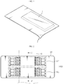
- FIG. 1 generally, when a pouch-type secondary battery 1 is completely cut, at least one corner is bent due to a stress remaining at the edge of the pouch to cause a curling portion 2, thereby deteriorating the product quality.
- Patent Literature 1 discloses a vacuum adsorption positioning forming mold, which vacuum-absorbs an aluminum pouch to allow satisfactory positioning when the aluminum pouch used for manufacturing a cellular phone battery is formed and cut.
- Patent Literature 2 directed to improving the warping phenomenon in a manufacturing process discloses a pouch exterior for a secondary battery and its manufacturing method, which has an accommodation portion in which an electrode assembly is accommodated and a groove is additionally formed along an edge region of the pouch exterior.
- the conventional techniques related to solving the curling problem of the pouch have a complicated device structure and may not be universally applied to a pouch-type secondary battery manufacturing process.
- the present disclosure is designed to solve the problems of the related art, and therefore the present disclosure is directed to providing a leveling apparatus, which may prevent a pouch from being curled after a cutting process by using a technical means for removing a stress existing at a rim portion of the pouch during a pouch-type secondary battery manufacturing procedure.
- a leveling apparatus used in a cutting process after forming process of a pouch-type secondary battery
- the leveling apparatus comprising: a roller assembly having pairs of upper rollers and lower rollers arranged in at least two rows to be capable of rolling in contact with upper and lower surfaces adjacent to both rim edges of a pouch-type secondary battery to which a pouch forming process is completely performed; and a support frame configured to support the roller assembly, wherein the roller assembly is configured to apply rolling with respect to the upper and lower surfaces adjacent to both rim edges of the pouch-type secondary battery thereby to remove stress.
- rollers may be disposed to be divided into a first roller set located at a relatively front portion based on a travelling direction of the pouch-type secondary battery and a second roller set located at a relatively rear portion.
- the support frame may include a first frame configured to support the first roller set and a second frame disposed to be spaced apart from the first frame to support the second roller set.
- the support frame may include an elongated hole and a guide bolt coupled to the elongated hole to adjust height and location of the frames in vertical and horizontal directions.
- the support frame may include an elongated hole and a guide bolt coupled to the elongated hole to adjust a gap between the upper rollers and the lower rollers.
- the lower rollers may be disposed obliquely from the upper rollers to be biased to one side from locations exactly opposed to the upper rollers with a predetermined deviation.
- the support frame may include: a lower unit provided at the support; and an upper unit mounted to the lower unit, and the roller assembly may be provided at the upper unit.
- the lower roller may be supported by a movable block provided at the upper unit.
- the movable block may be mounted to be movable with respect to the upper unit.
- the upper rollers and the lower rollers may be made of synthetic resin material that does not damage the surface of the pouch-type secondary battery.
- the present disclosure is applied, it is possible to manufacture a high quality pouch-type secondary battery in which the pouch has a uniform and flat rim portion.
- FIG. 2 is a plane view showing a leveling apparatus according to an embodiment of the present disclosure
- FIG. 3 is a cross-sectioned view, taken along the line A-A' of FIG. 2
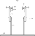
- FIG. 4 is a front view of FIG. 2 .
- a leveling apparatus includes a roller assembly 100 in which pairs of upper rollers 103 and lower rollers 104 are arranged in at least two rows, and a support frame 110 supporting the roller assembly 100.
- the leveling apparatus according to the present disclosure is used in a cutting process in which a rim edges is partially cut after forming process of the pouch-type secondary battery 10.
- the pouch-type secondary battery 10 to which the present disclosure is applied has a thin plate-like body as a whole, and includes a pouch case and an electrode assembly embedded in the pouch case and having a positive electrode, a separator and a negative electrode alternately stacked.
- the positive and negative electrodes are prepared by applying a slurry of an electrode active material, a binder resin, a conductive agent and other additives to at least one surface of a current collector.
- a common positive electrode active material such as a lithium-containing transition metal oxide may be used.
- a common negative electrode active material such as a lithium metal, a carbonaceous material, a metal compound, or mixtures thereof, which are capable of intercalating and deintercalating lithium ions, may be used.
- a common porous polymer film used in a lithium secondary battery may be employed as the separator.
- the pouch case is formed of a sheet material and has an accommodation portion for accommodating the electrode assembly.
- the pouch case is prepared by coupling a first case and a second case, which are formed by processing a sheet material into a predetermined shape.
- the sheet material of the pouch case has a multi-layered structure in which an outer resin layer made of an insulating material such as polyethylene terephthalate (PET) or nylon and provided at an outermost side, a metal layer made of aluminum to maintain the mechanical strength and prevent the penetration of moisture and oxygen, and an inner resin layer made of a polyolefin-based material having thermal adhesiveness to serve as a sealing material are laminated.
- PET polyethylene terephthalate
- nylon nylon
- an inner resin layer made of a polyolefin-based material having thermal adhesiveness to serve as a sealing material are laminated.
- a predetermined adhesive resin layer may be interposed between the inner resin layer and the metal layer and between the outer resin layer and the metal layer, if necessary.
- the adhesive resin layer is intended for good adhesion between dissimilar materials and is formed as a single layer or a multilayer.
- the material of the adhesive resin layer is usually a polyolefin-based resin, or a polyurethane resin for smooth processing, or a mixture thereof.
- An edge portion of the pouch-type secondary battery 10 is a region sealed by thermal compression or the like.
- the edge portion of the pouch-type secondary battery 10 has a relatively small thickness compared to a body portion.
- the leveling apparatus receives the pouch-type secondary battery 10 configured as above, and during a cutting process of cutting a part of a rim edge of the pouch, rolls both surfaces thereof near the rim edge by using a plurality of rollers to remove stress and prevent the occurrence of curling.
- a driving force for supplying the pouch-type secondary battery 10 may be obtained by a separate conveyor device.
- a predetermined driving unit may be added to the leveling apparatus to generate a driving force for supplying the pouch-type secondary battery 10.
- the roller assembly 100 includes plural pairs of upper rollers 103 and lower rollers 104 which simultaneously perform rolling in contact with both upper and lower surfaces adjacent to both rim edges of the pouch-type secondary battery 10 to which a pouch forming process is completed.
- the pairs of upper rollers 103 and lower rollers 104 of the roller assembly 100 are arranged in at least two rows based on a travelling direction (a feeding direction) of the pouch-type secondary battery 10 to correspond to both surfaces thereof, as shown in FIG. 2 .
- the upper rollers 103 and the lower rollers 104 are preferably made of a synthetic resin material that does not damage the surface of the pouch because they are in direct contact with the upper and lower surfaces of the pouch-type secondary battery 10.
- rollers are disposed to be divided into a first roller set 101 located at a relatively front portion (forwards) and a second roller set 102 located at a relatively rear portion based on the travelling direction of the pouch-type secondary battery 10.
- the positions of the pairs of upper rollers 103 and lower rollers 104 may be precisely adjusted suitable for the size of the pouch-type secondary battery 10 that requires a leveling work. Also, if any roller needs to be repaired, only a roller set at which the corresponding roller is located may be easily disassembled, so it is easy to maintain the rollers.
- the support frame 110 is assembled to vertically erect on the support 120 to support the roller assembly 100.
- the support frame 110 includes a first frame 111 configured to support the first roller set 101 and a second frame 112 disposed to be spaced apart from the first frame 111 in a front direction based on the travelling direction of the pouch-type secondary battery 10 to support the second roller set 102.
- the support frame 110 may be configured using a combination of rigid metal plates or blocks.
- the first frame 111 and the second frame 112 may be provided as an assembly of a lower unit 113 and an upper unit 114, respectively.
- the support frame 110 may include a lower unit 113 provided at the support 120 and an upper unit 114 mounted to the lower unit 113.
- the roller assembly 100 may be provided at the upper unit 114.
- the support frame 110 includes an elongated hole 115 for adjusting the position of the frame in a lateral direction with respect to the support 120, and a guide bolt 116 inserted into the elongated hole 115 and fastened thereto by screwing.
- the support frame 110 includes an elongated hole 117 for adjusting the height of the frame in a vertical direction with respect to the support 120, and a guide bolt (not shown) inserted into the elongated hole 117 and fastened thereto by screwing.
- the upper unit 114 and the lower unit 113 of the first frame 111 and the second frame 112 are fixed by adjusting the positions thereof so that the guide bolt 116 is capable of sliding along the elongated hole 115, and then tightening the guide bolt 116. By this adjustment, the gap between the first roller set 101 and the second roller set 102 may be controlled.
- the support frame 110 includes an elongated hole 118 for adjusting the gap between the upper roller 103 and the lower roller 104, and a guide bolt 119 inserted into the elongated hole 118 and fastened thereto by screwing.
- the lower roller 104 is supported by a movable block 121 provided at the upper unit 114, and the gap between the upper roller 103 and the lower roller 104 may be adjusted by moving the movable block 121 with respect to the upper unit 114.
- the movable block 121 may be mounted to be movable with respect to the upper unit 114. Specifically, the movable block 121 is positioned so that the guide bolt 119 is capable of sliding along the elongated hole 118, and then is fixed by fastening the guide bolt 119 so that the location of the lower roller 104 is set with respect to the upper roller 103.
- the rolling strength for removing the stress during the rolling operation may be adjusted, thereby making it possible to precisely control the curling prevention function.
- the lower rollers 104 are disposed somewhat obliquely from the upper rollers 103 to be biased to one side from locations exactly opposed to the upper rollers 103 with a predetermined deviation d.
- the lower rollers 104 are disposed to be biased to the front to more stably support the pouch-type secondary battery 10.
- the leveling apparatus removes stress and thereby prevents the occurrence of curling since the roller assembly 100 is configured to apply rolling with respect to the upper and lower surfaces near both rim edges of the pouch-type secondary battery 10 thereby.
- the pouch-type secondary battery 10 in a completely formed state is fed so that both rim edges are interposed between the plural pairs of upper rollers 103 and lower rollers 104 that are arranged in two rows.
- the plural pairs of upper rollers 103 and lower rollers 104 of the roller assembly 100 remove the stress generated in the previous process and remaining at the present by applying a physical force, generated by rolling, to the upper and lower surfaces near both rim edges of the pouch.
- the plural pairs of upper rollers 103 and lower rollers 104 simultaneously perform a rolling operation with respect to the upper and lower surfaces of the pouch-type secondary battery 10. At this time, the rolling strength may be optimized by adjusting the gap between the upper roller 103 and the lower roller 104.
- a cutting process for cutting a part of the rim edge of the pouch-type secondary battery 10 is performed in a state where the stress existing at the rim edge of the pouch-type secondary battery 10 is removed by using the roller assembly 100 of the leveling apparatus as described above, the curling phenomenon that a corner of the pouch is bent does not occur since the stress is removed in advance.
- the leveling apparatus As described above, if the leveling apparatus according to the present disclosure is applied, the occurrence of curling at the corner portion is prevented during the cutting process for the pouch-type secondary battery, and thus it is possible to manufacture a high quality pouch-type secondary battery at which the rim portion of the pouch maintains uniform flatness.
Landscapes
- Chemical & Material Sciences (AREA)
- Chemical Kinetics & Catalysis (AREA)
- Electrochemistry (AREA)
- General Chemical & Material Sciences (AREA)
- Engineering & Computer Science (AREA)
- Mechanical Engineering (AREA)
- Manufacturing & Machinery (AREA)
- Sealing Battery Cases Or Jackets (AREA)
- Secondary Cells (AREA)
- Cell Separators (AREA)
- Battery Electrode And Active Subsutance (AREA)
Abstract
Description
- The present disclosure relates to a leveling apparatus used for manufacturing a pouch-type secondary battery, and more particularly, to a leveling apparatus used in a pouch cutting process of a pouch-type secondary battery manufacturing procedure.
- The present application claims priority to Korean Patent Application No.
10-2017-0034958 filed on March 20, 2017 - Generally, a method of manufacturing a pouch-type secondary battery includes the steps of injecting an electrolyte through an electrolyte injection portion located at one side of a rim region of a prepared pouch-type secondary battery, primarily sealing the electrolyte injection portion along a primary sealing line and then performing charging/discharging, cutting a part of the electrolyte injection portion along a cutting line located at an inner side of the primary sealing line, performing degassing, secondarily sealing the electrolyte injection portion, and cutting a part of the electrolyte injection portion along a cutting line located at an outer side of the secondary sealing line.
- In addition, after the pouch is completely formed, a cutting process is performed to cut unnecessary portions of the edge area of the pouch.
- However, as shown in
FIG. 1 , generally, when a pouch-type secondary battery 1 is completely cut, at least one corner is bent due to a stress remaining at the edge of the pouch to cause acurling portion 2, thereby deteriorating the product quality. - In relation to this problem, in order to prevent the problem that the pouch is rolled up due to the forming pressure, Patent Literature 1 discloses a vacuum adsorption positioning forming mold, which vacuum-absorbs an aluminum pouch to allow satisfactory positioning when the aluminum pouch used for manufacturing a cellular phone battery is formed and cut.
- As another alternative,
Patent Literature 2 directed to improving the warping phenomenon in a manufacturing process discloses a pouch exterior for a secondary battery and its manufacturing method, which has an accommodation portion in which an electrode assembly is accommodated and a groove is additionally formed along an edge region of the pouch exterior. - However, the conventional techniques related to solving the curling problem of the pouch have a complicated device structure and may not be universally applied to a pouch-type secondary battery manufacturing process.
-
- Patent Literature 1: Korean Unexamined Patent Publication No.
2004-0079531 - Patent Literature 2: Korean Unexamined Patent Publication No.
2014-0132528 - The present disclosure is designed to solve the problems of the related art, and therefore the present disclosure is directed to providing a leveling apparatus, which may prevent a pouch from being curled after a cutting process by using a technical means for removing a stress existing at a rim portion of the pouch during a pouch-type secondary battery manufacturing procedure.
- In one aspect of the present disclosure, there is provided a leveling apparatus used in a cutting process after forming process of a pouch-type secondary battery, the leveling apparatus comprising: a roller assembly having pairs of upper rollers and lower rollers arranged in at least two rows to be capable of rolling in contact with upper and lower surfaces adjacent to both rim edges of a pouch-type secondary battery to which a pouch forming process is completely performed; and a support frame configured to support the roller assembly, wherein the roller assembly is configured to apply rolling with respect to the upper and lower surfaces adjacent to both rim edges of the pouch-type secondary battery thereby to remove stress.
- In the roller assembly, rollers may be disposed to be divided into a first roller set located at a relatively front portion based on a travelling direction of the pouch-type secondary battery and a second roller set located at a relatively rear portion.
- The support frame may include a first frame configured to support the first roller set and a second frame disposed to be spaced apart from the first frame to support the second roller set.
- The support frame may include an elongated hole and a guide bolt coupled to the elongated hole to adjust height and location of the frames in vertical and horizontal directions.
- The support frame may include an elongated hole and a guide bolt coupled to the elongated hole to adjust a gap between the upper rollers and the lower rollers.
- The lower rollers may be disposed obliquely from the upper rollers to be biased to one side from locations exactly opposed to the upper rollers with a predetermined deviation.
- The support frame may include: a lower unit provided at the support; and an upper unit mounted to the lower unit, and the roller assembly may be provided at the upper unit.
- The lower roller may be supported by a movable block provided at the upper unit.
- The movable block may be mounted to be movable with respect to the upper unit.
- The upper rollers and the lower rollers may be made of synthetic resin material that does not damage the surface of the pouch-type secondary battery.
- According to the present disclosure, it is possible to suppress curling during a cutting process by applying a physical force to upper and lower surfaces near a rim edge of a pouch using rollers to remove the stress.
- Thus, if the present disclosure is applied, it is possible to manufacture a high quality pouch-type secondary battery in which the pouch has a uniform and flat rim portion.
- The accompanying drawings illustrate a preferred embodiment of the present disclosure and together with the foregoing disclosure, serve to provide further understanding of the technical features of the present disclosure, and thus, the present disclosure is not construed as being limited to the drawing.
-
FIG. 1 is a perspective view showing an example where curling occurs at a pouch-type secondary battery when a pouch is formed and then completely cut according to the conventional art. -
FIG. 2 is a plane view showing a leveling apparatus according to an embodiment of the present disclosure. -
FIG. 3 is a cross-sectioned view, taken along the line A-A' ofFIG. 2 . -
FIG. 4 is a front view ofFIG. 2 . - Hereinafter, preferred embodiments of the present disclosure will be described in detail with reference to the accompanying drawings. Prior to the description, it should be understood that the terms used in the specification and the appended claims should not be construed as limited to general and dictionary meanings, but interpreted based on the meanings and concepts corresponding to technical aspects of the present disclosure on the basis of the principle that the inventor is allowed to define terms appropriately for the best explanation. Therefore, the description proposed herein is just a preferable example for the purpose of illustrations only, not intended to limit the scope of the disclosure, so it should be understood that other equivalents and modifications could be made thereto without departing from the scope of the disclosure.
-
FIG. 2 is a plane view showing a leveling apparatus according to an embodiment of the present disclosure,FIG. 3 is a cross-sectioned view, taken along the line A-A' ofFIG. 2 , andFIG. 4 is a front view ofFIG. 2 . - Referring to
FIGS. 2 to 4 , a leveling apparatus according to an embodiment of the present disclosure includes aroller assembly 100 in which pairs ofupper rollers 103 andlower rollers 104 are arranged in at least two rows, and asupport frame 110 supporting theroller assembly 100. - The leveling apparatus according to the present disclosure is used in a cutting process in which a rim edges is partially cut after forming process of the pouch-type
secondary battery 10. - The pouch-type
secondary battery 10 to which the present disclosure is applied has a thin plate-like body as a whole, and includes a pouch case and an electrode assembly embedded in the pouch case and having a positive electrode, a separator and a negative electrode alternately stacked. The positive and negative electrodes are prepared by applying a slurry of an electrode active material, a binder resin, a conductive agent and other additives to at least one surface of a current collector. In the positive electrode, a common positive electrode active material such as a lithium-containing transition metal oxide may be used. In the negative electrode, a common negative electrode active material such as a lithium metal, a carbonaceous material, a metal compound, or mixtures thereof, which are capable of intercalating and deintercalating lithium ions, may be used. In addition, as the separator, a common porous polymer film used in a lithium secondary battery may be employed. - As the electrolyte accommodated in the pouch case together with the electrode assembly, a common electrolyte for a lithium secondary battery may be employed. The pouch case is formed of a sheet material and has an accommodation portion for accommodating the electrode assembly. Preferably, the pouch case is prepared by coupling a first case and a second case, which are formed by processing a sheet material into a predetermined shape. The sheet material of the pouch case has a multi-layered structure in which an outer resin layer made of an insulating material such as polyethylene terephthalate (PET) or nylon and provided at an outermost side, a metal layer made of aluminum to maintain the mechanical strength and prevent the penetration of moisture and oxygen, and an inner resin layer made of a polyolefin-based material having thermal adhesiveness to serve as a sealing material are laminated.
- In the sheet material of the pouch case, a predetermined adhesive resin layer may be interposed between the inner resin layer and the metal layer and between the outer resin layer and the metal layer, if necessary. The adhesive resin layer is intended for good adhesion between dissimilar materials and is formed as a single layer or a multilayer. The material of the adhesive resin layer is usually a polyolefin-based resin, or a polyurethane resin for smooth processing, or a mixture thereof.
- An edge portion of the pouch-type
secondary battery 10 is a region sealed by thermal compression or the like. Thus, the edge portion of the pouch-typesecondary battery 10 has a relatively small thickness compared to a body portion. - The leveling apparatus according to the present disclosure receives the pouch-type
secondary battery 10 configured as above, and during a cutting process of cutting a part of a rim edge of the pouch, rolls both surfaces thereof near the rim edge by using a plurality of rollers to remove stress and prevent the occurrence of curling. - Here, a driving force for supplying the pouch-type
secondary battery 10 may be obtained by a separate conveyor device. Alternatively, a predetermined driving unit may be added to the leveling apparatus to generate a driving force for supplying the pouch-typesecondary battery 10. - The
roller assembly 100 includes plural pairs ofupper rollers 103 andlower rollers 104 which simultaneously perform rolling in contact with both upper and lower surfaces adjacent to both rim edges of the pouch-typesecondary battery 10 to which a pouch forming process is completed. - The pairs of
upper rollers 103 andlower rollers 104 of theroller assembly 100 are arranged in at least two rows based on a travelling direction (a feeding direction) of the pouch-typesecondary battery 10 to correspond to both surfaces thereof, as shown inFIG. 2 . - The
upper rollers 103 and thelower rollers 104 are preferably made of a synthetic resin material that does not damage the surface of the pouch because they are in direct contact with the upper and lower surfaces of the pouch-typesecondary battery 10. - In the
roller assembly 100, rollers are disposed to be divided into afirst roller set 101 located at a relatively front portion (forwards) and asecond roller set 102 located at a relatively rear portion based on the travelling direction of the pouch-typesecondary battery 10. - According to the divided arrangement, the positions of the pairs of
upper rollers 103 andlower rollers 104 may be precisely adjusted suitable for the size of the pouch-typesecondary battery 10 that requires a leveling work. Also, if any roller needs to be repaired, only a roller set at which the corresponding roller is located may be easily disassembled, so it is easy to maintain the rollers. - As shown in
FIG. 3 , thesupport frame 110 is assembled to vertically erect on thesupport 120 to support theroller assembly 100. Thesupport frame 110 includes afirst frame 111 configured to support the first roller set 101 and asecond frame 112 disposed to be spaced apart from thefirst frame 111 in a front direction based on the travelling direction of the pouch-typesecondary battery 10 to support the second roller set 102. - The
support frame 110 may be configured using a combination of rigid metal plates or blocks. Preferably, thefirst frame 111 and thesecond frame 112 may be provided as an assembly of alower unit 113 and anupper unit 114, respectively. - Specifically, the
support frame 110 may include alower unit 113 provided at thesupport 120 and anupper unit 114 mounted to thelower unit 113. Here, theroller assembly 100 may be provided at theupper unit 114. - The
support frame 110 includes anelongated hole 115 for adjusting the position of the frame in a lateral direction with respect to thesupport 120, and aguide bolt 116 inserted into theelongated hole 115 and fastened thereto by screwing. - In addition, the
support frame 110 includes anelongated hole 117 for adjusting the height of the frame in a vertical direction with respect to thesupport 120, and a guide bolt (not shown) inserted into theelongated hole 117 and fastened thereto by screwing. - The
upper unit 114 and thelower unit 113 of thefirst frame 111 and thesecond frame 112 are fixed by adjusting the positions thereof so that theguide bolt 116 is capable of sliding along theelongated hole 115, and then tightening theguide bolt 116. By this adjustment, the gap between the first roller set 101 and the second roller set 102 may be controlled. - In addition, the
support frame 110 includes anelongated hole 118 for adjusting the gap between theupper roller 103 and thelower roller 104, and aguide bolt 119 inserted into theelongated hole 118 and fastened thereto by screwing. As shown inFIG. 4 , thelower roller 104 is supported by amovable block 121 provided at theupper unit 114, and the gap between theupper roller 103 and thelower roller 104 may be adjusted by moving themovable block 121 with respect to theupper unit 114. - Here, the
movable block 121 may be mounted to be movable with respect to theupper unit 114. Specifically, themovable block 121 is positioned so that theguide bolt 119 is capable of sliding along theelongated hole 118, and then is fixed by fastening theguide bolt 119 so that the location of thelower roller 104 is set with respect to theupper roller 103. - If the gap between the
upper roller 103 and thelower roller 104 is adjusted, the rolling strength for removing the stress during the rolling operation may be adjusted, thereby making it possible to precisely control the curling prevention function. - Seeing the arrangement of the
upper rollers 103 and thelower rollers 104, as shown inFIG. 3 , it is advantageous in terms of ensuring sufficient rolling strength for the upper and lower surfaces of the pouch that thelower rollers 104 are disposed somewhat obliquely from theupper rollers 103 to be biased to one side from locations exactly opposed to theupper rollers 103 with a predetermined deviation d. Considering the travelling direction of the pouch-typesecondary battery 10 as shown inFIG. 3 , it is preferable that thelower rollers 104 are disposed to be biased to the front to more stably support the pouch-typesecondary battery 10. - The leveling apparatus according to an embodiment of the presenting disclosure, configured as above, removes stress and thereby prevents the occurrence of curling since the
roller assembly 100 is configured to apply rolling with respect to the upper and lower surfaces near both rim edges of the pouch-typesecondary battery 10 thereby. - The pouch-type
secondary battery 10 in a completely formed state is fed so that both rim edges are interposed between the plural pairs ofupper rollers 103 andlower rollers 104 that are arranged in two rows. - The plural pairs of
upper rollers 103 andlower rollers 104 of theroller assembly 100 remove the stress generated in the previous process and remaining at the present by applying a physical force, generated by rolling, to the upper and lower surfaces near both rim edges of the pouch. - The plural pairs of
upper rollers 103 andlower rollers 104 simultaneously perform a rolling operation with respect to the upper and lower surfaces of the pouch-typesecondary battery 10. At this time, the rolling strength may be optimized by adjusting the gap between theupper roller 103 and thelower roller 104. - If a cutting process for cutting a part of the rim edge of the pouch-type
secondary battery 10 is performed in a state where the stress existing at the rim edge of the pouch-typesecondary battery 10 is removed by using theroller assembly 100 of the leveling apparatus as described above, the curling phenomenon that a corner of the pouch is bent does not occur since the stress is removed in advance. - As described above, if the leveling apparatus according to the present disclosure is applied, the occurrence of curling at the corner portion is prevented during the cutting process for the pouch-type secondary battery, and thus it is possible to manufacture a high quality pouch-type secondary battery at which the rim portion of the pouch maintains uniform flatness.
- The present disclosure has been described in detail. However, it should be understood that the detailed description and specific examples, while indicating preferred embodiments of the disclosure, are given by way of illustration only, since various changes and modifications within the scope of the disclosure will become apparent to those skilled in the art from this detailed description.
Claims (10)
- A leveling apparatus used in a cutting process after forming process of a pouch-type secondary battery, the leveling apparatus comprising:a roller assembly having pairs of upper rollers and lower rollers arranged in at least two rows to be capable of rolling in contact with upper and lower surfaces adjacent to both rim edges of a pouch-type secondary battery to which a pouch forming process is completely performed; anda support frame configured to support the roller assembly,wherein the roller assembly is configured to apply rolling with respect to the upper and lower surfaces adjacent to both rim edges of the pouch-type secondary battery thereby to remove stress.
- The leveling apparatus according to claim 1,
wherein in the roller assembly, rollers are disposed to be divided into a first roller set located at a relatively front portion based on a travelling direction of the pouch-type secondary battery and a second roller set located at a relatively rear portion. - The leveling apparatus according to claim 2,
wherein the support frame includes a first frame configured to support the first roller set and a second frame disposed to be spaced apart from the first frame to support the second roller set. - The leveling apparatus according to claim 3,
wherein the support frame includes an elongated hole and a guide bolt coupled to the elongated hole to adjust height and location of the frames in vertical and horizontal directions. - The leveling apparatus according to claim 3,
wherein the support frame includes an elongated hole and a guide bolt coupled to the elongated hole to adjust a gap between the upper rollers and the lower rollers. - The leveling apparatus according to claim 1,
wherein the lower rollers are disposed obliquely from the upper rollers to be biased to one side from locations exactly opposed to the upper rollers with a predetermined deviation. - The leveling apparatus according to claim 1,
wherein the support frame includes:a lower unit provided at the support; andan upper unit mounted to the lower unit,wherein the roller assembly is provided at the upper unit. - The leveling apparatus according to claim 7,
wherein the lower roller is supported by a movable block provided at the upper unit. - The leveling apparatus according to claim 8,
wherein the movable block is mounted to be movable with respect to the upper unit. - The leveling apparatus according to claim 1,
wherein the upper rollers and the lower rollers are made of synthetic resin material that does not damage the surface of the pouch-type secondary battery.
Applications Claiming Priority (2)
| Application Number | Priority Date | Filing Date | Title |
|---|---|---|---|
| KR1020170034958A KR102224911B1 (en) | 2017-03-20 | 2017-03-20 | Leveling apparatus for preventing curling of pouch type secondary battery |
| PCT/KR2018/002479 WO2018174423A1 (en) | 2017-03-20 | 2018-02-28 | Leveling device for preventing curling of pouch-type secondary battery |
Publications (3)
| Publication Number | Publication Date |
|---|---|
| EP3486084A1 true EP3486084A1 (en) | 2019-05-22 |
| EP3486084A4 EP3486084A4 (en) | 2019-09-25 |
| EP3486084B1 EP3486084B1 (en) | 2022-04-20 |
Family
ID=63585624
Family Applications (1)
| Application Number | Title | Priority Date | Filing Date |
|---|---|---|---|
| EP18770992.8A Active EP3486084B1 (en) | 2017-03-20 | 2018-02-28 | Leveling apparatus for preventing curling of pouch-type secondary battery |
Country Status (6)
| Country | Link |
|---|---|
| US (1) | US10777779B2 (en) |
| EP (1) | EP3486084B1 (en) |
| KR (1) | KR102224911B1 (en) |
| CN (1) | CN109689365B (en) |
| PL (1) | PL3486084T3 (en) |
| WO (1) | WO2018174423A1 (en) |
Families Citing this family (7)
| Publication number | Priority date | Publication date | Assignee | Title |
|---|---|---|---|---|
| KR102831129B1 (en) | 2020-03-16 | 2025-07-04 | 주식회사 엘지에너지솔루션 | Sealing device and method secondary battery |
| KR102343421B1 (en) * | 2020-04-25 | 2021-12-27 | 주식회사 클레버 | Device for aligning pouch type secondary battery |
| KR20230009141A (en) * | 2021-07-08 | 2023-01-17 | 주식회사 엘지에너지솔루션 | Pouch Curling Prevention Device |
| KR102922205B1 (en) | 2021-07-16 | 2026-02-04 | 주식회사 엘지에너지솔루션 | Manufacturing apparatus of pouch type battery case |
| KR20240122162A (en) | 2023-02-03 | 2024-08-12 | 주식회사 엘지에너지솔루션 | Curl adjusting apparatus of pouch sheet and pouch sheet transferring method using the same |
| KR20250058611A (en) * | 2023-10-23 | 2025-04-30 | 주식회사 엘지에너지솔루션 | Pouch cutting appartus |
| KR20250131127A (en) * | 2024-02-26 | 2025-09-02 | 주식회사 엘지에너지솔루션 | Apparatus for forming pouch case and method for forming pouch case |
Family Cites Families (17)
| Publication number | Priority date | Publication date | Assignee | Title |
|---|---|---|---|---|
| US3890160A (en) | 1973-09-20 | 1975-06-17 | Gen Motors Corp | Method and apparatus for preventing curling of lead strips during expansion |
| WO1997034329A1 (en) * | 1996-03-14 | 1997-09-18 | Fuji Photo Film Co., Ltd. | Method and device for sticking lithium foil and method for manufacturing lithium electrode |
| CN1193195A (en) * | 1997-03-11 | 1998-09-16 | 富士摄影胶片株式会社 | Device for working winded-body of cell, method and device for transfering same |
| JP3661439B2 (en) * | 1998-10-07 | 2005-06-15 | 松下電器産業株式会社 | Battery electrode and method and apparatus for manufacturing the same |
| KR20040079531A (en) | 2003-03-07 | 2004-09-16 | 에프원 주식회사 | Vacuum-absorption type positioning forming mold for aluminum pouch |
| KR101108118B1 (en) * | 2008-11-27 | 2012-01-31 | 주식회사 엠플러스 | Secondary Battery Manufacturing Method and Secondary Battery |
| KR200458494Y1 (en) | 2009-04-10 | 2012-02-22 | 전순희 | Manufacturing Appratus for pouch |
| KR101417152B1 (en) | 2009-10-09 | 2014-08-07 | 주식회사 엘지화학 | Method for manufacturing pouch type battery and sealing device for pouch |
| KR101362108B1 (en) * | 2012-03-20 | 2014-02-13 | (주)한서정공 | Apparatus for harvesting soybean |
| KR20140132528A (en) | 2013-05-08 | 2014-11-18 | 주식회사 엘지화학 | Pouch case for secondary battery and method for manufacturing secondary battery using the same |
| KR20140136831A (en) | 2013-05-21 | 2014-12-01 | 주식회사 엘지화학 | Pouch for secondary battery and method for manufacturing the same |
| KR20140147372A (en) * | 2013-06-19 | 2014-12-30 | 삼성전기주식회사 | Substrate warpage compensator |
| KR101763980B1 (en) | 2013-08-30 | 2017-08-01 | 주식회사 엘지화학 | Sealiing tool of pouch type secondary battery |
| KR101838315B1 (en) | 2013-10-18 | 2018-03-13 | 주식회사 엘지화학 | Method For Manufacturing Pouch Type Lithium Secondary Battery |
| US9859535B2 (en) * | 2014-09-30 | 2018-01-02 | Panasonic Intellectual Property Management Co., Ltd. | Pouch-type battery and method of manufacturing the same |
| US9287566B1 (en) | 2015-04-17 | 2016-03-15 | Chang Chun Petrochemical Co., Ltd. | Anti-curl copper foil |
| KR102348074B1 (en) * | 2015-05-19 | 2022-01-11 | 에스케이온 주식회사 | Pouch sealing apparatus and method of manufacturing secondary battery |
-
2017
- 2017-03-20 KR KR1020170034958A patent/KR102224911B1/en active Active
-
2018
- 2018-02-28 WO PCT/KR2018/002479 patent/WO2018174423A1/en not_active Ceased
- 2018-02-28 EP EP18770992.8A patent/EP3486084B1/en active Active
- 2018-02-28 PL PL18770992.8T patent/PL3486084T3/en unknown
- 2018-02-28 US US16/316,734 patent/US10777779B2/en active Active
- 2018-02-28 CN CN201880003403.8A patent/CN109689365B/en active Active
Also Published As
| Publication number | Publication date |
|---|---|
| WO2018174423A1 (en) | 2018-09-27 |
| EP3486084B1 (en) | 2022-04-20 |
| US10777779B2 (en) | 2020-09-15 |
| EP3486084A4 (en) | 2019-09-25 |
| PL3486084T3 (en) | 2022-08-22 |
| CN109689365B (en) | 2021-04-09 |
| US20190207172A1 (en) | 2019-07-04 |
| KR20180106523A (en) | 2018-10-01 |
| KR102224911B1 (en) | 2021-03-05 |
| CN109689365A (en) | 2019-04-26 |
Similar Documents
| Publication | Publication Date | Title |
|---|---|---|
| EP3486084B1 (en) | Leveling apparatus for preventing curling of pouch-type secondary battery | |
| KR101099903B1 (en) | Battery pole plate, battery pole plate group, lithium secondary battery, manufacturing method of battery electrode plate, and battery electrode plate manufacturing apparatus | |
| EP4342623A1 (en) | Electrode manufacturing device used for laser notching of electrode | |
| EP3955355A1 (en) | Multi-plate laminating device for lithium battery cell and laminating method thereof | |
| US10336490B2 (en) | Taping machine for attaching insulation tape to outer peripheral sealing part of battery cell | |
| KR101604052B1 (en) | Removal equipment for a electric conduction plate of electric double layer capacitors battery for electric vehicle | |
| KR20170117681A (en) | Taping Apparatus Capable of Attaching Adhesive Tape to Battery Cell | |
| CN104969399B (en) | Battery Cell Stacking Fixture | |
| EP3823061B1 (en) | Active material coating method for secondary battery and coating apparatus | |
| KR102493563B1 (en) | Manufacturing method of pouch film for secondary battery of lithium ion | |
| KR102695825B1 (en) | Pouch side processing apparatus and method of pouch type battery cell | |
| US20220140304A1 (en) | Slitter | |
| KR20220032670A (en) | Device of manufacturing a secondary battery | |
| KR20180107859A (en) | Device for Eliminating Gas from Activated Battery Cell | |
| KR20210108758A (en) | Apparatus for rolling electrode | |
| US12230779B2 (en) | Cathode for secondary battery and method for manufacturing same | |
| KR200493852Y1 (en) | Electrode Lamination Device Comprising Feeding Conveyor | |
| KR101708358B1 (en) | Electrode plate manufacturing system and method | |
| US20230048828A1 (en) | Rolling Device for Secondary Battery | |
| KR102504756B1 (en) | Lamination apparatus and Lamination method for electrode | |
| KR20200103473A (en) | Pouch for secondary battery case, secondary battery and method of manufacturing the same | |
| KR102003712B1 (en) | Electrode Tab-Feeding Device Comprising Guide for Positioning Electrode Tab at Correct Point | |
| EP4212311A1 (en) | Pouch sealing apparatus | |
| EP4645404A1 (en) | Electrode production apparatus and battery cells comprising electrodes produced thereby, and battery pack and vehicle comprising battery cells | |
| KR20180091481A (en) | Apparatus and Method for assembling battery cell cover |
Legal Events
| Date | Code | Title | Description |
|---|---|---|---|
| STAA | Information on the status of an ep patent application or granted ep patent |
Free format text: STATUS: THE INTERNATIONAL PUBLICATION HAS BEEN MADE |
|
| PUAI | Public reference made under article 153(3) epc to a published international application that has entered the european phase |
Free format text: ORIGINAL CODE: 0009012 |
|
| STAA | Information on the status of an ep patent application or granted ep patent |
Free format text: STATUS: REQUEST FOR EXAMINATION WAS MADE |
|
| 17P | Request for examination filed |
Effective date: 20190213 |
|
| AK | Designated contracting states |
Kind code of ref document: A1 Designated state(s): AL AT BE BG CH CY CZ DE DK EE ES FI FR GB GR HR HU IE IS IT LI LT LU LV MC MK MT NL NO PL PT RO RS SE SI SK SM TR |
|
| AX | Request for extension of the european patent |
Extension state: BA ME |
|
| A4 | Supplementary search report drawn up and despatched |
Effective date: 20190826 |
|
| RIC1 | Information provided on ipc code assigned before grant |
Ipc: H01M 10/04 20060101ALI20190820BHEP Ipc: B32B 38/00 20060101AFI20190820BHEP Ipc: H01M 2/02 20060101ALI20190820BHEP Ipc: B32B 43/00 20060101ALI20190820BHEP Ipc: B65H 23/34 20060101ALI20190820BHEP |
|
| DAV | Request for validation of the european patent (deleted) | ||
| DAX | Request for extension of the european patent (deleted) | ||
| RIC1 | Information provided on ipc code assigned before grant |
Ipc: B65H 23/34 20060101ALI20210930BHEP Ipc: H01M 50/10 20210101ALI20210930BHEP Ipc: H01M 10/04 20060101ALI20210930BHEP Ipc: H01M 50/116 20210101ALI20210930BHEP Ipc: B32B 43/00 20060101ALI20210930BHEP Ipc: B32B 38/00 20060101AFI20210930BHEP |
|
| GRAP | Despatch of communication of intention to grant a patent |
Free format text: ORIGINAL CODE: EPIDOSNIGR1 |
|
| STAA | Information on the status of an ep patent application or granted ep patent |
Free format text: STATUS: GRANT OF PATENT IS INTENDED |
|
| INTG | Intention to grant announced |
Effective date: 20211129 |
|
| RAP1 | Party data changed (applicant data changed or rights of an application transferred) |
Owner name: LG ENERGY SOLUTION LTD. |
|
| GRAS | Grant fee paid |
Free format text: ORIGINAL CODE: EPIDOSNIGR3 |
|
| GRAA | (expected) grant |
Free format text: ORIGINAL CODE: 0009210 |
|
| STAA | Information on the status of an ep patent application or granted ep patent |
Free format text: STATUS: THE PATENT HAS BEEN GRANTED |
|
| RAP3 | Party data changed (applicant data changed or rights of an application transferred) |
Owner name: LG ENERGY SOLUTION, LTD. |
|
| AK | Designated contracting states |
Kind code of ref document: B1 Designated state(s): AL AT BE BG CH CY CZ DE DK EE ES FI FR GB GR HR HU IE IS IT LI LT LU LV MC MK MT NL NO PL PT RO RS SE SI SK SM TR |
|
| REG | Reference to a national code |
Ref country code: GB Ref legal event code: FG4D |
|
| REG | Reference to a national code |
Ref country code: CH Ref legal event code: EP |
|
| REG | Reference to a national code |
Ref country code: DE Ref legal event code: R096 Ref document number: 602018034210 Country of ref document: DE |
|
| REG | Reference to a national code |
Ref country code: IE Ref legal event code: FG4D |
|
| REG | Reference to a national code |
Ref country code: AT Ref legal event code: REF Ref document number: 1484873 Country of ref document: AT Kind code of ref document: T Effective date: 20220515 |
|
| REG | Reference to a national code |
Ref country code: SE Ref legal event code: TRGR |
|
| REG | Reference to a national code |
Ref country code: LT Ref legal event code: MG9D |
|
| REG | Reference to a national code |
Ref country code: NL Ref legal event code: MP Effective date: 20220420 |
|
| REG | Reference to a national code |
Ref country code: AT Ref legal event code: MK05 Ref document number: 1484873 Country of ref document: AT Kind code of ref document: T Effective date: 20220420 |
|
| PG25 | Lapsed in a contracting state [announced via postgrant information from national office to epo] |
Ref country code: NL Free format text: LAPSE BECAUSE OF FAILURE TO SUBMIT A TRANSLATION OF THE DESCRIPTION OR TO PAY THE FEE WITHIN THE PRESCRIBED TIME-LIMIT Effective date: 20220420 |
|
| PG25 | Lapsed in a contracting state [announced via postgrant information from national office to epo] |
Ref country code: PT Free format text: LAPSE BECAUSE OF FAILURE TO SUBMIT A TRANSLATION OF THE DESCRIPTION OR TO PAY THE FEE WITHIN THE PRESCRIBED TIME-LIMIT Effective date: 20220822 Ref country code: NO Free format text: LAPSE BECAUSE OF FAILURE TO SUBMIT A TRANSLATION OF THE DESCRIPTION OR TO PAY THE FEE WITHIN THE PRESCRIBED TIME-LIMIT Effective date: 20220720 Ref country code: LT Free format text: LAPSE BECAUSE OF FAILURE TO SUBMIT A TRANSLATION OF THE DESCRIPTION OR TO PAY THE FEE WITHIN THE PRESCRIBED TIME-LIMIT Effective date: 20220420 Ref country code: HR Free format text: LAPSE BECAUSE OF FAILURE TO SUBMIT A TRANSLATION OF THE DESCRIPTION OR TO PAY THE FEE WITHIN THE PRESCRIBED TIME-LIMIT Effective date: 20220420 Ref country code: GR Free format text: LAPSE BECAUSE OF FAILURE TO SUBMIT A TRANSLATION OF THE DESCRIPTION OR TO PAY THE FEE WITHIN THE PRESCRIBED TIME-LIMIT Effective date: 20220721 Ref country code: FI Free format text: LAPSE BECAUSE OF FAILURE TO SUBMIT A TRANSLATION OF THE DESCRIPTION OR TO PAY THE FEE WITHIN THE PRESCRIBED TIME-LIMIT Effective date: 20220420 Ref country code: ES Free format text: LAPSE BECAUSE OF FAILURE TO SUBMIT A TRANSLATION OF THE DESCRIPTION OR TO PAY THE FEE WITHIN THE PRESCRIBED TIME-LIMIT Effective date: 20220420 Ref country code: BG Free format text: LAPSE BECAUSE OF FAILURE TO SUBMIT A TRANSLATION OF THE DESCRIPTION OR TO PAY THE FEE WITHIN THE PRESCRIBED TIME-LIMIT Effective date: 20220720 Ref country code: AT Free format text: LAPSE BECAUSE OF FAILURE TO SUBMIT A TRANSLATION OF THE DESCRIPTION OR TO PAY THE FEE WITHIN THE PRESCRIBED TIME-LIMIT Effective date: 20220420 |
|
| PG25 | Lapsed in a contracting state [announced via postgrant information from national office to epo] |
Ref country code: RS Free format text: LAPSE BECAUSE OF FAILURE TO SUBMIT A TRANSLATION OF THE DESCRIPTION OR TO PAY THE FEE WITHIN THE PRESCRIBED TIME-LIMIT Effective date: 20220420 Ref country code: LV Free format text: LAPSE BECAUSE OF FAILURE TO SUBMIT A TRANSLATION OF THE DESCRIPTION OR TO PAY THE FEE WITHIN THE PRESCRIBED TIME-LIMIT Effective date: 20220420 Ref country code: IS Free format text: LAPSE BECAUSE OF FAILURE TO SUBMIT A TRANSLATION OF THE DESCRIPTION OR TO PAY THE FEE WITHIN THE PRESCRIBED TIME-LIMIT Effective date: 20220820 |
|
| REG | Reference to a national code |
Ref country code: DE Ref legal event code: R097 Ref document number: 602018034210 Country of ref document: DE |
|
| PG25 | Lapsed in a contracting state [announced via postgrant information from national office to epo] |
Ref country code: SM Free format text: LAPSE BECAUSE OF FAILURE TO SUBMIT A TRANSLATION OF THE DESCRIPTION OR TO PAY THE FEE WITHIN THE PRESCRIBED TIME-LIMIT Effective date: 20220420 Ref country code: SK Free format text: LAPSE BECAUSE OF FAILURE TO SUBMIT A TRANSLATION OF THE DESCRIPTION OR TO PAY THE FEE WITHIN THE PRESCRIBED TIME-LIMIT Effective date: 20220420 Ref country code: RO Free format text: LAPSE BECAUSE OF FAILURE TO SUBMIT A TRANSLATION OF THE DESCRIPTION OR TO PAY THE FEE WITHIN THE PRESCRIBED TIME-LIMIT Effective date: 20220420 Ref country code: EE Free format text: LAPSE BECAUSE OF FAILURE TO SUBMIT A TRANSLATION OF THE DESCRIPTION OR TO PAY THE FEE WITHIN THE PRESCRIBED TIME-LIMIT Effective date: 20220420 Ref country code: DK Free format text: LAPSE BECAUSE OF FAILURE TO SUBMIT A TRANSLATION OF THE DESCRIPTION OR TO PAY THE FEE WITHIN THE PRESCRIBED TIME-LIMIT Effective date: 20220420 Ref country code: CZ Free format text: LAPSE BECAUSE OF FAILURE TO SUBMIT A TRANSLATION OF THE DESCRIPTION OR TO PAY THE FEE WITHIN THE PRESCRIBED TIME-LIMIT Effective date: 20220420 |
|
| PLBE | No opposition filed within time limit |
Free format text: ORIGINAL CODE: 0009261 |
|
| STAA | Information on the status of an ep patent application or granted ep patent |
Free format text: STATUS: NO OPPOSITION FILED WITHIN TIME LIMIT |
|
| 26N | No opposition filed |
Effective date: 20230123 |
|
| PG25 | Lapsed in a contracting state [announced via postgrant information from national office to epo] |
Ref country code: AL Free format text: LAPSE BECAUSE OF FAILURE TO SUBMIT A TRANSLATION OF THE DESCRIPTION OR TO PAY THE FEE WITHIN THE PRESCRIBED TIME-LIMIT Effective date: 20220420 |
|
| PG25 | Lapsed in a contracting state [announced via postgrant information from national office to epo] |
Ref country code: SI Free format text: LAPSE BECAUSE OF FAILURE TO SUBMIT A TRANSLATION OF THE DESCRIPTION OR TO PAY THE FEE WITHIN THE PRESCRIBED TIME-LIMIT Effective date: 20220420 |
|
| P01 | Opt-out of the competence of the unified patent court (upc) registered |
Effective date: 20230408 |
|
| PG25 | Lapsed in a contracting state [announced via postgrant information from national office to epo] |
Ref country code: MC Free format text: LAPSE BECAUSE OF FAILURE TO SUBMIT A TRANSLATION OF THE DESCRIPTION OR TO PAY THE FEE WITHIN THE PRESCRIBED TIME-LIMIT Effective date: 20220420 |
|
| REG | Reference to a national code |
Ref country code: CH Ref legal event code: PL |
|
| REG | Reference to a national code |
Ref country code: BE Ref legal event code: MM Effective date: 20230228 |
|
| PG25 | Lapsed in a contracting state [announced via postgrant information from national office to epo] |
Ref country code: LU Free format text: LAPSE BECAUSE OF NON-PAYMENT OF DUE FEES Effective date: 20230228 Ref country code: LI Free format text: LAPSE BECAUSE OF NON-PAYMENT OF DUE FEES Effective date: 20230228 Ref country code: CH Free format text: LAPSE BECAUSE OF NON-PAYMENT OF DUE FEES Effective date: 20230228 |
|
| REG | Reference to a national code |
Ref country code: IE Ref legal event code: MM4A |
|
| PG25 | Lapsed in a contracting state [announced via postgrant information from national office to epo] |
Ref country code: IT Free format text: LAPSE BECAUSE OF FAILURE TO SUBMIT A TRANSLATION OF THE DESCRIPTION OR TO PAY THE FEE WITHIN THE PRESCRIBED TIME-LIMIT Effective date: 20220420 Ref country code: IE Free format text: LAPSE BECAUSE OF NON-PAYMENT OF DUE FEES Effective date: 20230228 |
|
| PG25 | Lapsed in a contracting state [announced via postgrant information from national office to epo] |
Ref country code: BE Free format text: LAPSE BECAUSE OF NON-PAYMENT OF DUE FEES Effective date: 20230228 |
|
| PG25 | Lapsed in a contracting state [announced via postgrant information from national office to epo] |
Ref country code: BG Free format text: LAPSE BECAUSE OF FAILURE TO SUBMIT A TRANSLATION OF THE DESCRIPTION OR TO PAY THE FEE WITHIN THE PRESCRIBED TIME-LIMIT Effective date: 20220420 |
|
| PG25 | Lapsed in a contracting state [announced via postgrant information from national office to epo] |
Ref country code: BG Free format text: LAPSE BECAUSE OF FAILURE TO SUBMIT A TRANSLATION OF THE DESCRIPTION OR TO PAY THE FEE WITHIN THE PRESCRIBED TIME-LIMIT Effective date: 20220420 |
|
| PG25 | Lapsed in a contracting state [announced via postgrant information from national office to epo] |
Ref country code: CY Free format text: LAPSE BECAUSE OF FAILURE TO SUBMIT A TRANSLATION OF THE DESCRIPTION OR TO PAY THE FEE WITHIN THE PRESCRIBED TIME-LIMIT; INVALID AB INITIO Effective date: 20180228 |
|
| PG25 | Lapsed in a contracting state [announced via postgrant information from national office to epo] |
Ref country code: HU Free format text: LAPSE BECAUSE OF FAILURE TO SUBMIT A TRANSLATION OF THE DESCRIPTION OR TO PAY THE FEE WITHIN THE PRESCRIBED TIME-LIMIT; INVALID AB INITIO Effective date: 20180228 |
|
| PG25 | Lapsed in a contracting state [announced via postgrant information from national office to epo] |
Ref country code: TR Free format text: LAPSE BECAUSE OF FAILURE TO SUBMIT A TRANSLATION OF THE DESCRIPTION OR TO PAY THE FEE WITHIN THE PRESCRIBED TIME-LIMIT Effective date: 20220420 |
|
| PGFP | Annual fee paid to national office [announced via postgrant information from national office to epo] |
Ref country code: SE Payment date: 20260121 Year of fee payment: 9 |
|
| PGFP | Annual fee paid to national office [announced via postgrant information from national office to epo] |
Ref country code: GB Payment date: 20260122 Year of fee payment: 9 |
|
| PGFP | Annual fee paid to national office [announced via postgrant information from national office to epo] |
Ref country code: DE Payment date: 20260120 Year of fee payment: 9 |
|
| PGFP | Annual fee paid to national office [announced via postgrant information from national office to epo] |
Ref country code: FR Payment date: 20260121 Year of fee payment: 9 |
|
| PGFP | Annual fee paid to national office [announced via postgrant information from national office to epo] |
Ref country code: PL Payment date: 20260120 Year of fee payment: 9 |