EP3485991A1 - Rolling facility and rolling method of stainless steel plate - Google Patents
Rolling facility and rolling method of stainless steel plate Download PDFInfo
- Publication number
- EP3485991A1 EP3485991A1 EP17828009.5A EP17828009A EP3485991A1 EP 3485991 A1 EP3485991 A1 EP 3485991A1 EP 17828009 A EP17828009 A EP 17828009A EP 3485991 A1 EP3485991 A1 EP 3485991A1
- Authority
- EP
- European Patent Office
- Prior art keywords
- rolling
- workpiece
- surface gloss
- gas
- measuring
- Prior art date
- Legal status (The legal status is an assumption and is not a legal conclusion. Google has not performed a legal analysis and makes no representation as to the accuracy of the status listed.)
- Withdrawn
Links
- 238000005096 rolling process Methods 0.000 title claims abstract description 177
- 238000000034 method Methods 0.000 title claims abstract description 22
- 229910001220 stainless steel Inorganic materials 0.000 title claims abstract description 17
- 239000010935 stainless steel Substances 0.000 title claims abstract description 17
- 238000001816 cooling Methods 0.000 claims abstract description 91
- 239000010731 rolling oil Substances 0.000 claims abstract description 44
- 238000004804 winding Methods 0.000 claims abstract description 4
- 239000007789 gas Substances 0.000 claims description 90
- 229910000831 Steel Inorganic materials 0.000 claims description 30
- 239000010959 steel Substances 0.000 claims description 30
- IJGRMHOSHXDMSA-UHFFFAOYSA-N Atomic nitrogen Chemical compound N#N IJGRMHOSHXDMSA-UHFFFAOYSA-N 0.000 claims description 8
- 239000012530 fluid Substances 0.000 claims description 8
- 229910052757 nitrogen Inorganic materials 0.000 claims description 4
- 238000005259 measurement Methods 0.000 abstract description 5
- 230000007547 defect Effects 0.000 description 15
- 238000004441 surface measurement Methods 0.000 description 6
- 238000010586 diagram Methods 0.000 description 5
- 238000002347 injection Methods 0.000 description 3
- 239000007924 injection Substances 0.000 description 3
- 230000003247 decreasing effect Effects 0.000 description 2
- 230000000694 effects Effects 0.000 description 2
- 238000005461 lubrication Methods 0.000 description 2
- 238000003825 pressing Methods 0.000 description 2
- 229910000589 SAE 304 stainless steel Inorganic materials 0.000 description 1
- 239000002826 coolant Substances 0.000 description 1
- 239000002480 mineral oil Substances 0.000 description 1
- 235000010446 mineral oil Nutrition 0.000 description 1
- 239000003921 oil Substances 0.000 description 1
- 230000002441 reversible effect Effects 0.000 description 1
- 238000007127 saponification reaction Methods 0.000 description 1
- 239000000243 solution Substances 0.000 description 1
- 239000002436 steel type Substances 0.000 description 1
Images



Classifications
-
- B—PERFORMING OPERATIONS; TRANSPORTING
- B21—MECHANICAL METAL-WORKING WITHOUT ESSENTIALLY REMOVING MATERIAL; PUNCHING METAL
- B21B—ROLLING OF METAL
- B21B1/00—Metal-rolling methods or mills for making semi-finished products of solid or profiled cross-section; Sequence of operations in milling trains; Layout of rolling-mill plant, e.g. grouping of stands; Succession of passes or of sectional pass alternations
- B21B1/22—Metal-rolling methods or mills for making semi-finished products of solid or profiled cross-section; Sequence of operations in milling trains; Layout of rolling-mill plant, e.g. grouping of stands; Succession of passes or of sectional pass alternations for rolling plates, strips, bands or sheets of indefinite length
- B21B1/24—Metal-rolling methods or mills for making semi-finished products of solid or profiled cross-section; Sequence of operations in milling trains; Layout of rolling-mill plant, e.g. grouping of stands; Succession of passes or of sectional pass alternations for rolling plates, strips, bands or sheets of indefinite length in a continuous or semi-continuous process
-
- B—PERFORMING OPERATIONS; TRANSPORTING
- B21—MECHANICAL METAL-WORKING WITHOUT ESSENTIALLY REMOVING MATERIAL; PUNCHING METAL
- B21B—ROLLING OF METAL
- B21B13/00—Metal-rolling stands, i.e. an assembly composed of a stand frame, rolls, and accessories
- B21B13/02—Metal-rolling stands, i.e. an assembly composed of a stand frame, rolls, and accessories with axes of rolls arranged horizontally
-
- B—PERFORMING OPERATIONS; TRANSPORTING
- B21—MECHANICAL METAL-WORKING WITHOUT ESSENTIALLY REMOVING MATERIAL; PUNCHING METAL
- B21B—ROLLING OF METAL
- B21B27/00—Rolls, roll alloys or roll fabrication; Lubricating, cooling or heating rolls while in use
- B21B27/06—Lubricating, cooling or heating rolls
- B21B27/10—Lubricating, cooling or heating rolls externally
-
- B—PERFORMING OPERATIONS; TRANSPORTING
- B21—MECHANICAL METAL-WORKING WITHOUT ESSENTIALLY REMOVING MATERIAL; PUNCHING METAL
- B21B—ROLLING OF METAL
- B21B3/00—Rolling materials of special alloys so far as the composition of the alloy requires or permits special rolling methods or sequences ; Rolling of aluminium, copper, zinc or other non-ferrous metals
- B21B3/02—Rolling special iron alloys, e.g. stainless steel
-
- B—PERFORMING OPERATIONS; TRANSPORTING
- B21—MECHANICAL METAL-WORKING WITHOUT ESSENTIALLY REMOVING MATERIAL; PUNCHING METAL
- B21B—ROLLING OF METAL
- B21B37/00—Control devices or methods specially adapted for metal-rolling mills or the work produced thereby
-
- B—PERFORMING OPERATIONS; TRANSPORTING
- B21—MECHANICAL METAL-WORKING WITHOUT ESSENTIALLY REMOVING MATERIAL; PUNCHING METAL
- B21B—ROLLING OF METAL
- B21B37/00—Control devices or methods specially adapted for metal-rolling mills or the work produced thereby
- B21B37/007—Control for preventing or reducing vibration, chatter or chatter marks
-
- B—PERFORMING OPERATIONS; TRANSPORTING
- B21—MECHANICAL METAL-WORKING WITHOUT ESSENTIALLY REMOVING MATERIAL; PUNCHING METAL
- B21B—ROLLING OF METAL
- B21B38/00—Methods or devices for measuring, detecting or monitoring specially adapted for metal-rolling mills, e.g. position detection, inspection of the product
-
- B—PERFORMING OPERATIONS; TRANSPORTING
- B21—MECHANICAL METAL-WORKING WITHOUT ESSENTIALLY REMOVING MATERIAL; PUNCHING METAL
- B21B—ROLLING OF METAL
- B21B45/00—Devices for surface or other treatment of work, specially combined with or arranged in, or specially adapted for use in connection with, metal-rolling mills
- B21B45/02—Devices for surface or other treatment of work, specially combined with or arranged in, or specially adapted for use in connection with, metal-rolling mills for lubricating, cooling, or cleaning
- B21B45/0203—Cooling
- B21B45/0209—Cooling devices, e.g. using gaseous coolants
-
- B—PERFORMING OPERATIONS; TRANSPORTING
- B21—MECHANICAL METAL-WORKING WITHOUT ESSENTIALLY REMOVING MATERIAL; PUNCHING METAL
- B21B—ROLLING OF METAL
- B21B27/00—Rolls, roll alloys or roll fabrication; Lubricating, cooling or heating rolls while in use
- B21B27/06—Lubricating, cooling or heating rolls
- B21B27/10—Lubricating, cooling or heating rolls externally
- B21B2027/103—Lubricating, cooling or heating rolls externally cooling externally
-
- B—PERFORMING OPERATIONS; TRANSPORTING
- B21—MECHANICAL METAL-WORKING WITHOUT ESSENTIALLY REMOVING MATERIAL; PUNCHING METAL
- B21B—ROLLING OF METAL
- B21B45/00—Devices for surface or other treatment of work, specially combined with or arranged in, or specially adapted for use in connection with, metal-rolling mills
- B21B45/02—Devices for surface or other treatment of work, specially combined with or arranged in, or specially adapted for use in connection with, metal-rolling mills for lubricating, cooling, or cleaning
- B21B45/0203—Cooling
- B21B45/0209—Cooling devices, e.g. using gaseous coolants
- B21B2045/0212—Cooling devices, e.g. using gaseous coolants using gaseous coolants
-
- B—PERFORMING OPERATIONS; TRANSPORTING
- B21—MECHANICAL METAL-WORKING WITHOUT ESSENTIALLY REMOVING MATERIAL; PUNCHING METAL
- B21B—ROLLING OF METAL
- B21B2261/00—Product parameters
- B21B2261/14—Roughness
-
- B—PERFORMING OPERATIONS; TRANSPORTING
- B21—MECHANICAL METAL-WORKING WITHOUT ESSENTIALLY REMOVING MATERIAL; PUNCHING METAL
- B21B—ROLLING OF METAL
- B21B37/00—Control devices or methods specially adapted for metal-rolling mills or the work produced thereby
- B21B37/74—Temperature control, e.g. by cooling or heating the rolls or the product
-
- B—PERFORMING OPERATIONS; TRANSPORTING
- B21—MECHANICAL METAL-WORKING WITHOUT ESSENTIALLY REMOVING MATERIAL; PUNCHING METAL
- B21B—ROLLING OF METAL
- B21B45/00—Devices for surface or other treatment of work, specially combined with or arranged in, or specially adapted for use in connection with, metal-rolling mills
- B21B45/02—Devices for surface or other treatment of work, specially combined with or arranged in, or specially adapted for use in connection with, metal-rolling mills for lubricating, cooling, or cleaning
- B21B45/0239—Lubricating
- B21B45/0245—Lubricating devices
- B21B45/0248—Lubricating devices using liquid lubricants, e.g. for sections, for tubes
- B21B45/0251—Lubricating devices using liquid lubricants, e.g. for sections, for tubes for strips, sheets, or plates
Definitions
- the present disclosure relates to a rolling mill and a method of rolling a stainless steel sheet.
- Continuous rolling as a method for rolling a workpiece to a target thickness by allowing the workpiece, which becomes a rolled workpiece, to pass through a plurality of working rolls, provided in a conveying direction of a workpiece, once, is a rolling method providing significantly excellent productivity.
- a working roll, used for continuous rolling has a relatively large diameter as compared with a working roll used for reversible rolling, and viscosity of rolling oil is high. Moreover, since the number of rolling mills, arranged throughout an entire rolling line, is limited, a reduction rate per unit stand is high, which may be high reduction rolling conditions.
- a heat streak defect is a defect occurring when a surface is damaged due to surface adhesion between a roll and a workpiece, and is then transferred to a workpiece. Moreover, a heat streak defect is a defect frequently occurring in high strength and high reduction rolling conditions such as in rolling stainless steel.
- a roll is cooled using a coolant.
- viscosity of an oil film of rolling oil is increased, while surface gloss of a workpiece is lowered.
- An aspect of the present disclosure is to improve quality while suppressing occurrence of a defect.
- An aspect of the present disclosure is to perform high-speed rolling at a constant quality, and to improve productivity.
- a rolling mill and a method of rolling a stainless steel sheet are provided.
- the rolling mill includes: a plurality of rolling roll sets, composed of at least a pair of rolls opposing each other with a workpiece being conveyed interposed therebetween, and provided in a conveying direction of the workpiece; a plurality of rolling oil supply devices, provided corresponding to each of the rolling roll sets, for supplying rolling oil to the rolling roll sets; a plurality of cooling devices, provided corresponding to each of the rolling roll sets, for supplying a gas to the workpiece and the rolling roll sets; a gloss measuring device, disposed between a rolling roll set most rearwardly disposed in a moving direction of the workpiece and a winder for winding the workpiece to measure surface gloss of the workpiece; and a control device, connected to the gloss measuring device and the plurality of cooling devices to control an amount of gas supplied by the plurality of cooling devices according to surface gloss measured by the gloss measuring device.
- the gloss measuring device may be provided as a plurality of gloss measuring devices, the plurality of gloss measuring devices being provided between an outlet of a leading rolling roll set in the conveying direction of the workpiece and an inlet of a trailing rolling roll set and measuring surface gloss of the workpiece in real time, and the control device may be connected to the plurality of gloss measuring devices and the plurality of cooling devices to control an amount of gas, supplied by the cooling device followed by the gloss measuring device, based on an error between surface gloss measured by the gloss measuring device, and target surface gloss of the workpiece.
- the gloss measuring device may measure surface gloss of the workpiece in real time, and the control device may receive the surface gloss, measured by the gloss measuring device, to generate a measured surface gloss value, and may control a supply amount of gas, supplied by the plurality of cooling devices, based on an error between a target surface gloss value of the workpiece, and the measured surface gloss value.
- the control device may generate a total supply amount of gas based on an error between a target surface gloss value of the workpiece and the measured surface gloss value, may control a total amount of gas, supplied by the plurality of cooling devices, at least to be equal to the total supply amount of gas, and may control the plurality of cooling devices to supply different amounts of gas.
- the cooling device may include: a cooling housing, provided in an inlet and an outlet of each of the rolling roll sets; a first supply pipe and a second supply pipe, connected to a gas supply tank, and provided in the cooling housing; a first nozzle, provided in the first supply pipe, and supplying gas to the workpiece; a second nozzle, provided in the second supply pipe, and supplying gas to a gap between the rolls, through which the workpiece passes; and a first flow control valve and a second flow control valve, provided in the first supply pipe and the second supply pipe and connected to the control device.
- the control device may perform PI control, and may control at least one, of the first flow control valve and the second flow control valve, to increase a flow rate of at least one of the first supply pipe and the second supply pipe when the measured surface gloss value is greater than the target surface gloss value, and to reduce a flow rate of at least one of the first supply pipe and the second supply pipe when the measured surface gloss value is less than the target surface gloss value.
- the gloss measuring device may include: a measuring housing, installed on a conveying path of the workpiece; a measuring roll, provided to move in the measuring housing and in a state of contact or non-contact with the workpiece; a light emitting unit, provided in the measuring roll, and allowing light to be incident on a surface of the workpiece; and a light receiving unit, provided in the measuring roll, and measuring light reflected from a surface of the workpiece.
- Gas, stored in the gas supply tank, may be liquefied nitrogen.
- Another aspect of the present disclosure is to provide a rolling method of a stainless steel sheet, allowing a surface of a stainless steel sheet to have a target surface gloss value by including a plurality of rolling roll sets, provided as a pair of rolls opposing each other, in a moving direction of the steel sheet, and the rolling method includes: fluid supplying, for supplying rolling oil and gas for cooling to each of the rolling roll sets; surface measuring, for measuring a surface gloss value of the steel sheet in real time, between an outlet of a rolling roll set most rearwardly disposed in a moving direction of the steel sheet and a front end of a winder of the steel sheet; and flow rate controlling, for controlling an amount of gas, supplied in the fluid supplying, according to a difference between the measured surface gloss value, measured in the surface measuring, and a target surface gloss value.
- a surface gloss value of the steel sheet may be measured in real time between an outlet of a leading rolling roll set in a conveying direction of the steel sheet and an inlet of a trailing rolling roll set, and, in the flow rate controlling, an amount of gas, supplied to each of the rolling roll sets, may be controlled according to a difference between each measured surface gloss value, measured in the surface measuring, and a target surface gloss value set for each of the rolling roll sets.
- a supply amount of gas, supplied in the fluid supplying may be changed.
- defect occurrence in detail, surface defect occurrence may be suppressed.
- the rolling mill 1000 may include a rolling roll set 100 including working rolls 110 opposing each other with a workpiece 10, being conveyed, interposed therebetween, an intermediate roll 120, and a backup roll 130.
- the rolling roll set 100 may be provided as a plurality of rolling roll sets in a conveying direction of the workpiece 10, and is referred to as a first rolling roll set 100a, a second rolling roll set 100b, and a third rolling roll set 100c for convenience of explanation.
- Each rolling roll set may include at least a pair of working rolls 110, a pair of intermediate rolls 120, and a pair of backup rolls 130.
- the rolling oil supply device 200 may include a rolling oil supply tank 210 accommodating rolling oil, a rolling oil supply pipe 220 provided as a moving path of the rolling oil accommodated in the rolling oil supply tank, and a rolling oil supply housing 230 connected to the rolling oil supply pipe 220 and disposed around the rolling roll set.
- the rolling oil supply housing 230 is provided in each of an inlet and an outlet of the working roll 110, and may include a nozzle (not shown) injecting rolling oil into a roll. Moreover, the rolling oil supply housing 230 may include a first housing 230a supplying rolling oil to the first rolling roll set 100a, a second housing 230b supplying rolling oil to the second rolling roll set 100b, and a third housing 230c supplying rolling oil to the third rolling roll set 100c.
- rolling oil supplied by the rolling oil supply device 200, may act between a roll and a workpiece to help smooth rolling.
- a temperature of the rolling oil may also rise.
- a cooling housing 310 may be provided in one side of the rolling oil supply housing 230. Moreover, the cooling housing 310 is also provided corresponding to the first rolling roll set 100a, the second rolling roll set 100b, and the third rolling roll set 100c on a one-by-one basis, in a manner similar to the rolling oil supply housing 230.
- a type of the gas for cooling is not limited to the present disclosure, and the number of the cooling housing 310 provided in the first rolling roll set 100a is also not limited to the present disclosure and may be suitably modified and applied by those skilled in the art.
- the gas supply tank 600 and the cooling housing 310, accommodating gas for cooling, may be connected by a pipe unit 350.
- the pipe unit 350 may be provided with a valve unit 360 to control a flow rate of gas.
- the valve unit 360 may include a first valve unit 360a, a second valve unit 360b, and a third valve unit 360c, to control gas for cooling to be supplied to the first rolling roll set, the second rolling roll set, and the third rolling roll set.
- first valve unit 360a, the second valve unit 360b, and the third valve unit 360c are connected to the control device 500, and the control device 500 may control the first valve unit 360a, the second valve unit 360b, and the third valve unit 360c according to a surface gloss value of a workpiece, measured by the gloss measuring device 400, to control a flow rate of gas for cooling.
- surface gloss of the workpiece 10, which is to be a rolled workpiece is measured in real time, and the surface gloss is compared with a target surface gloss value. Then, based on the comparison, a supply amount of gas for cooling is controlled.
- the gloss measuring device 400 measures surface gloss of the workpiece 10 in real time between the third rolling roll set 100c and the winder 800, and the control device 500 receives the surface gloss, measured by the gloss measuring device 400, to generate a measured surface gloss value, and may control an amount of gas for cooling, supplied through the cooling housing 310, based on an error between a target surface gloss value of the workpiece, and the measured surface gloss value, measured by the gloss measuring device 400.
- the target surface gloss value of the workpiece 10 is a desired surface gloss value
- the measured surface gloss value, measured by the gloss measuring device 400 is at least equal to the target surface gloss value to achieve a desired surface quality
- an amount of gas for cooling, supplied by the third rolling roll set 100c may be more sensitively controlled as compared with an amount of gas for cooling, supplied by the first rolling roll set 100a and the second rolling roll set 100b.
- the gloss measuring device 400 is provided between an outlet of the first rolling roll set 100a and an inlet of the second rolling roll set 100b, between an outlet of the second rolling roll set and an inlet of the third rolling roll set, and between an outlet of the third rolling roll set and the winder 800.
- information on surface gloss measured by the gloss measuring device 400 provided between the outlet of the first rolling roll set 100a and the inlet of the second rolling roll set 100b may be information on the workpiece 10, only passing through the first rolling roll set 100a, and other gloss measuring devices also measure surface gloss in a similar manner.
- control device 500 may receive information on surface gloss of the workpiece 10 for each rolling operation, and may control a supply amount of gas for cooling for each rolling operation.
- a flow rate of gas for cooling is controlled through the first valve unit 360a in the operation described above to adjust viscosity of rolling oil to an appropriate level.
- a rolling state is checked at the beginning of rolling of the workpiece 10 to significantly reduce a defect rate, and an amount of gas for cooling, to be supplied to the second rolling roll set 100b and the third rolling roll set 100c, may be expected, based on a measured surface gloss value by the first rolling roll set 100a.
- cooling device 300 of the present disclosure will be described with reference to FIG. 3 .
- the cooling device 300 may include a cooling housing 310, provided in an inlet and an outlet of each of the first rolling roll set, the second rolling roll set, and the third rolling roll set (100a, 100b, and 100c of FIGS. 1 and 2 ), and the cooling housing 310 may be provided as a plurality of cooling housings as needed in a single rolling roll set.
- the cooling housing 310 is provided with a pipe unit 350, connected to the gas supply tank 600 and provided as a moving path of gas for cooling, and the pipe unit 350 may include a first supply pipe 320 and a second supply pipe 330, passing through one surface of the workpiece 10.
- the first supply pipe 320 is provided with a plurality of first nozzles 321 in a longitudinal direction, and the first nozzle 321 is provided to allow an injection hole to oppose one surface of the workpiece 10 and may supply gas for cooling to the workpiece 10.
- the second supply pipe 330 is provided with a plurality of second nozzles 331 in a longitudinal direction, and the second nozzle 331 is disposed to allow an injection hole to oppose a gap between the working rolls 110 and supply gas for cooling to the working roll 110 or to a gap between working rolls 110 vertically opposing each other.
- gas for cooling supplied to a workpiece and a working roll, may be individually controlled, so individual cooling control may be performed according to a cooling state of a workpiece and a working roll.
- a first flow control valve 322 and a second flow control valve 332 may be provided on each of the first supply pipe 320 and the second supply pipe 330.
- the first flow control valve 322 and the second flow control valve 332 are connected to a control device 500, and whether the first flow control valve and the second flow control valve are open or closed is controlled by the control device 500, so a flow rate of gas for cooling, supplied by the gas supply tank 600, may be controlled.
- the control device 500 calculates a difference between a measured surface gloss value and a target surface gloss value, and thus may calculate a total supply amount of gas for cooling according to a difference value therbetween. Moreover, in order to achieve the total supply amount, as illustrated in FIG. 2 or FIG. 3 , an amount of gas for cooling, supplied by the first nozzle or the second nozzle (321 or 331 of FIG. 3 ) installed in the cooling housing 310, sequentially disposed in a conveying direction of the workpiece 10, may be the same or different from each other.
- an amount of gas supplied by the first nozzle or the second nozzle installed in the cooling housing 310 supplying gas for cooling to the first rolling roll set 100a, an amount of gas supplied by the first nozzle or the second nozzle installed in the cooling housing 310 supplying gas for cooling to the second rolling roll set 100b, and an amount of gas supplied by the first nozzle or the second nozzle installed in the cooling housing 310 supplying gas for cooling to the third rolling roll set 100c may be the same or different from each other.
- gas is supplied to the first rolling roll set 100a, the second rolling roll set 100b, and the third rolling roll set 100c, to allow the sum of an amount of gas for cooling, supplied through the first nozzle or the second nozzle provided in the cooling housing 310 installed in the first rolling roll set 100a, the second rolling roll set 100b, and the third rolling roll set 100c, to be at least equal to a total amount of gas for cooling, having been calculated.
- an amount of gas for cooling, supplied to the first rolling roll set 100a, among the first rolling roll set 100a, the second rolling roll set 100b, and the third rolling roll set 100c, is the smallest, while an amount of gas for cooling, supplied to the third rolling roll set 100c, may be the greatest.
- the workpiece 10 is air-cooled while being transferred from the first rolling roll set 100a to the third rolling roll set 100c, minimum cooling may be performed in the first rolling roll set 100a.
- the workpiece 10 may be prevented from being excessively cooled before reaching the third rolling roll set 100c.
- FIG. 4 a gloss measuring device 400 according to an exemplary embodiment is illustrated.
- the gloss measuring device 400 may include a measuring housing 410 installed on a conveying path of the workpiece 10, a measuring roll 420 provided to move in a direction of the workpiece 10 in the measuring housing 410 and in a state of contact or non-contact with a surface of the workpiece 10, a light emitting unit 430 provided in the measuring roll, and allowing light to be incident on a surface of the workpiece, and a light receiving unit 440 provided in the measuring roll and measuring light reflected from a surface of the workpiece.
- a guide member 450 allowing the measuring roll 420 to be lifted or lowered may be provided on both sides of the measuring housing 410.
- the guide member 450 is connected to a rotating shaft (not shown) of the measuring roll 420, and may be connected by a bearing member (not shown) to allow the measuring roll 420 to rotate.
- the guide member 450 may allow the measuring roll 420 to be in contact with or in non-contact with a surface of the workpiece 10 by increasing or reducing its own length, and may be provided as a rack and a pinion gear, a linear guide, and the like, within the scope of such technical ideas.
- a type thereof is not limited to the present disclosure.
- the measuring roll 420 is provided with a measuring groove 460 in one side opposing the workpiece 10.
- the measuring groove 460 is a groove which is concave inwardly of a body of the measuring roll 420, and the light emitting unit 430 to allow light to be incident on a surface of the workpiece 10 and the light receiving unit 440 measuring light reflected from the surface of the workpiece 10 may be provided in the measuring groove 460.
- gloss of a surface of the workpiece 10 is measured through an intensity ratio of incident light and reflected light, by the light emitting unit 430 and the light receiving unit 440. Moreover, as described above, when the light emitting unit 430 and the light receiving unit 440 are provided in the measuring groove 460, light, reflected from an external source, may be blocked, so accuracy of measurement may be further improved.
- a buffer member (not shown), formed of a workpiece with high ductility, may be provided in an outer circumference of the measuring roll 420.
- another aspect of the present disclosure is to provide a rolling method for rolling to allow a surface of a stainless steel sheet to have a target surface gloss value by including a plurality of rolling roll sets, provided as a pair of rolls opposing each other, in a moving direction of the steel sheet.
- the rolling roll set may include a pair of working rolls, directly pressing a surface of a steel sheet, and may further include a pair of intermediate rolls, pressing the working roll, and a pair of backup rolls.
- the pair of working rolls, the pair of intermediate rolls, and the pair of backup rolls are referred to as a rolling roll set.
- a rolling method may include: fluid supplying (S910) for supplying rolling oil and gas for cooling to each of the rolling roll sets; surface measuring (S920) for measuring a surface gloss value of the steel sheet in real time, between an outlet of a rolling roll set most rearwardly disposed in a moving direction of the steel sheet and a front end of a winder of the steel sheet; and flow rate controlling (S930) for controlling an amount of gas, supplied in the fluid supplying, according to a difference between a measured surface gloss value, measured in the surface measuring, and a target surface gloss value.
- surface gloss one time may be measured between a rolling roll set most rearwardly disposed in a conveying direction of a steel sheet and a winder for winding the steel sheet, or surface gloss multiple times may be measured in an outlet of each of the rolling roll sets.
- gas for cooling supplied to a rolling roll set most rearwardly disposed, may be most sensitively controlled.
- the gas for cooling, supplied by the rolling roll set most rearwardly disposed has the greatest effect on surface gloss of the steel sheet.
- surface gloss of a steel sheet for each rolling operation may be controlled.
- a surface defect of a workpiece may be recognized at the beginning of a process, and a surface of a steel sheet according to each rolling operation may be controlled.
- the surface gloss value, measured in the surface measuring (S920) as described above, may be used for controlling an amount of gas for cooling in the flow rate controlling (S930) .
- a flow rate may be controlled according to final surface gloss in the flow rate controlling.
- a flow rate may be controlled according to individual surface gloss in the flow rate controlling.
- an amount of gas for cooling, supplied to each of the rolling roll sets may all be the same, or may all be different.
- an amount of gas for cooling, supplied to a rolling roll set is adjusted to be different for each rolling operation according to characteristics of a steel sheet and rolling conditions, precise control in which process characteristics are reflected may be performed, so quality may be improved.
- an amount of gas for cooling controlled in the flow rate controlling, may be controlled by a difference between a measured surface gloss value of a steel sheet, and a target surface gloss value to be achieved.
- the control described above, as illustrated in FIG. 6 may be performed, when the measured surface gloss value exceeds 110% of the target surface gloss value, or is less than 90% thereof.
- a supply amount of gas for cooling is increased.
- a supply amount of gas for cooling is reduced, so temperatures of a steel sheet, a working roll, and rolling oil are controlled.
- surface gloss of the steel sheet may be controlled in a normal range.
- the error value is out of the normal range (D).
- an amount of gas for cooling may be controlled by PI control.
- a workpiece of a rolled workpiece is stainless 304 steel white coil
- a thickness of an inlet workpiece is 3.0 to 4.0 mmt
- a total reduction rate is 50% to 60%
- rolling oil having been used, is mineral oil with viscosity of 12 to 18 cSt(@40°C) and a saponification value (SV) of 40 to 45 mgKOH/g
- SV saponification value
- a supply amount of gas for cooling at random times may be calculated according to [Equation 1].
- u t k p e t + k i ⁇ 0 t e ⁇ d ⁇
- a proportional control gain, and an integral control gain are values determined by a steel type, rolling conditions, and the like.
Landscapes
- Engineering & Computer Science (AREA)
- Mechanical Engineering (AREA)
- Metal Rolling (AREA)
Abstract
Description
- The present disclosure relates to a rolling mill and a method of rolling a stainless steel sheet.
- Continuous rolling, as a method for rolling a workpiece to a target thickness by allowing the workpiece, which becomes a rolled workpiece, to pass through a plurality of working rolls, provided in a conveying direction of a workpiece, once, is a rolling method providing significantly excellent productivity.
- A working roll, used for continuous rolling, has a relatively large diameter as compared with a working roll used for reversible rolling, and viscosity of rolling oil is high. Moreover, since the number of rolling mills, arranged throughout an entire rolling line, is limited, a reduction rate per unit stand is high, which may be high reduction rolling conditions.
- Thus, when a workpiece with high deformation resistance, such as stainless steel, is high-speed rolled under high reduction rolling conditions, a temperature in a roll bite is increased, so viscosity of rolling oil is lowered. Accordingly, lubrication performance of the rolling oil may be deteriorated, such that a surface defect such as a heat streak may occur.
- A heat streak defect is a defect occurring when a surface is damaged due to surface adhesion between a roll and a workpiece, and is then transferred to a workpiece. Moreover, a heat streak defect is a defect frequently occurring in high strength and high reduction rolling conditions such as in rolling stainless steel.
- Thus, in order to prevent such a defect from occurring, a roll is cooled using a coolant. In this case, as the roll is cooled, viscosity of an oil film of rolling oil is increased, while surface gloss of a workpiece is lowered.
- In other words, in order to prevent a surface defect of a workpiece, it is necessary to maintain proper viscosity of rolling oil. However, as viscosity of rolling oil is increased, there may be a problem in which surface gloss of a workpiece is lowered. In the case in which a workpiece in which surface gloss is significantly important, such as stainless steel, is rolled, the problem described above may be a more sensitive issue.
- An aspect of the present disclosure is to improve quality while suppressing occurrence of a defect.
- An aspect of the present disclosure is to perform high-speed rolling at a constant quality, and to improve productivity.
- According to an aspect of the present disclosure, a rolling mill and a method of rolling a stainless steel sheet are provided.
- The rolling mill according to the present disclosure includes: a plurality of rolling roll sets, composed of at least a pair of rolls opposing each other with a workpiece being conveyed interposed therebetween, and provided in a conveying direction of the workpiece; a plurality of rolling oil supply devices, provided corresponding to each of the rolling roll sets, for supplying rolling oil to the rolling roll sets; a plurality of cooling devices, provided corresponding to each of the rolling roll sets, for supplying a gas to the workpiece and the rolling roll sets; a gloss measuring device, disposed between a rolling roll set most rearwardly disposed in a moving direction of the workpiece and a winder for winding the workpiece to measure surface gloss of the workpiece; and a control device, connected to the gloss measuring device and the plurality of cooling devices to control an amount of gas supplied by the plurality of cooling devices according to surface gloss measured by the gloss measuring device.
- The gloss measuring device may be provided as a plurality of gloss measuring devices, the plurality of gloss measuring devices being provided between an outlet of a leading rolling roll set in the conveying direction of the workpiece and an inlet of a trailing rolling roll set and measuring surface gloss of the workpiece in real time, and the control device may be connected to the plurality of gloss measuring devices and the plurality of cooling devices to control an amount of gas, supplied by the cooling device followed by the gloss measuring device, based on an error between surface gloss measured by the gloss measuring device, and target surface gloss of the workpiece.
- The gloss measuring device may measure surface gloss of the workpiece in real time, and the control device may receive the surface gloss, measured by the gloss measuring device, to generate a measured surface gloss value, and may control a supply amount of gas, supplied by the plurality of cooling devices, based on an error between a target surface gloss value of the workpiece, and the measured surface gloss value.
- The control device may generate a total supply amount of gas based on an error between a target surface gloss value of the workpiece and the measured surface gloss value, may control a total amount of gas, supplied by the plurality of cooling devices, at least to be equal to the total supply amount of gas, and may control the plurality of cooling devices to supply different amounts of gas.
- The cooling device may include: a cooling housing, provided in an inlet and an outlet of each of the rolling roll sets; a first supply pipe and a second supply pipe, connected to a gas supply tank, and provided in the cooling housing; a first nozzle, provided in the first supply pipe, and supplying gas to the workpiece; a second nozzle, provided in the second supply pipe, and supplying gas to a gap between the rolls, through which the workpiece passes; and a first flow control valve and a second flow control valve, provided in the first supply pipe and the second supply pipe and connected to the control device.
- The control device may perform PI control, and may control at least one, of the first flow control valve and the second flow control valve, to increase a flow rate of at least one of the first supply pipe and the second supply pipe when the measured surface gloss value is greater than the target surface gloss value, and to reduce a flow rate of at least one of the first supply pipe and the second supply pipe when the measured surface gloss value is less than the target surface gloss value.
- The gloss measuring device may include: a measuring housing, installed on a conveying path of the workpiece; a measuring roll, provided to move in the measuring housing and in a state of contact or non-contact with the workpiece; a light emitting unit, provided in the measuring roll, and allowing light to be incident on a surface of the workpiece; and a light receiving unit, provided in the measuring roll, and measuring light reflected from a surface of the workpiece.
- Gas, stored in the gas supply tank, may be liquefied nitrogen.
- Another aspect of the present disclosure is to provide a rolling method of a stainless steel sheet, allowing a surface of a stainless steel sheet to have a target surface gloss value by including a plurality of rolling roll sets, provided as a pair of rolls opposing each other, in a moving direction of the steel sheet, and the rolling method includes: fluid supplying, for supplying rolling oil and gas for cooling to each of the rolling roll sets; surface measuring, for measuring a surface gloss value of the steel sheet in real time, between an outlet of a rolling roll set most rearwardly disposed in a moving direction of the steel sheet and a front end of a winder of the steel sheet; and flow rate controlling, for controlling an amount of gas, supplied in the fluid supplying, according to a difference between the measured surface gloss value, measured in the surface measuring, and a target surface gloss value.
- In the surface measuring, a surface gloss value of the steel sheet may be measured in real time between an outlet of a leading rolling roll set in a conveying direction of the steel sheet and an inlet of a trailing rolling roll set, and, in the flow rate controlling, an amount of gas, supplied to each of the rolling roll sets, may be controlled according to a difference between each measured surface gloss value, measured in the surface measuring, and a target surface gloss value set for each of the rolling roll sets.
- In the flow rate controlling, when the measured surface gloss value, measured in the surface measuring, exceeds 110% or is less than 90%, of a target surface gloss value for the rolling roll set, passing immediately before reaching a position in which surface gloss of the steel sheet is measured, a supply amount of gas, supplied in the fluid supplying, may be changed.
- In the flow rate controlling, the supply amount of gas may be controlled by PI control, and the supply amount (u(t)) of gas at random times may be determined by

ki is an integral control gain, and
e (t) is a value of a difference between a measured surface gloss value and a target surface gloss value at random times. - As set forth above, according to an exemplary embodiment, during rolling, defect occurrence, in detail, surface defect occurrence may be suppressed.
- Moreover, while high-speed rolling may be performed at a constant quality, productivity and quality may be improved.
-
-
FIG. 1 is a conceptual diagram of a rolling mill according to an exemplary embodiment. -
FIG. 2 is a conceptual diagram of a rolling mill according to another exemplary embodiment. -
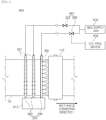
FIG. 3 is a conceptual diagram of a cooling device of the present disclosure. -
FIG. 4 is a conceptual diagram of a gloss measuring device of the present disclosure. -
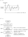
FIG. 5 is a conceptual diagram of a rolling method of a stainless steel sheet according to the present disclosure. -
FIG. 6 illustrates a difference between a measured surface gloss value, measured by a gloss measuring device of the present disclosure, and a target surface gloss value. - To help understand the description of embodiments of the present disclosure, elements denoted by the same reference numerals in the drawings are used for the same elements, and relevant components, among components having the same function in each of embodiments, are denoted by the same or an extension number.
- To clarify the gist of the present disclosure, description of elements and techniques known in the art will be omitted, and the present disclosure will be described in detail with reference to the accompanying drawings.
- The spirit of the present disclosure is not limited to the embodiments proposed, and may be suggested as other elements added, changed, and deleted by those skilled in the art, which is also included within the scope of the same concept as the present disclosure.
- In
FIG. 1 , arolling mill 1000 according to an exemplary embodiment is illustrated. Therolling mill 1000 according to an exemplary embodiment may include arolling roll set 100 includingworking rolls 110 opposing each other with aworkpiece 10, being conveyed, interposed therebetween, anintermediate roll 120, and abackup roll 130. - The
rolling roll set 100 may be provided as a plurality of rolling roll sets in a conveying direction of theworkpiece 10, and is referred to as a firstrolling roll set 100a, a secondrolling roll set 100b, and a third rolling roll set 100c for convenience of explanation. Each rolling roll set may include at least a pair ofworking rolls 110, a pair ofintermediate rolls 120, and a pair ofbackup rolls 130. - However, the present disclosure is not limited thereto, and the configuration and the number of rolling roll sets may be appropriately changed and applied by those skilled in the art.
- Rolling oil is supplied to each rolling roll set by a rolling
oil supply device 200. The rollingoil supply device 200 may include a rollingoil supply tank 210 accommodating rolling oil, a rollingoil supply pipe 220 provided as a moving path of the rolling oil accommodated in the rolling oil supply tank, and a rollingoil supply housing 230 connected to the rollingoil supply pipe 220 and disposed around the rolling roll set. - The rolling
oil supply housing 230 is provided in each of an inlet and an outlet of theworking roll 110, and may include a nozzle (not shown) injecting rolling oil into a roll. Moreover, the rollingoil supply housing 230 may include afirst housing 230a supplying rolling oil to the firstrolling roll set 100a, asecond housing 230b supplying rolling oil to the second rollingroll set 100b, and athird housing 230c supplying rolling oil to the third rollingroll set 100c. - Due to the configuration described above, rolling oil, supplied by the rolling
oil supply device 200, may act between a roll and a workpiece to help smooth rolling. However, as the working time continues and a temperature of the roll rises, a temperature of the rolling oil may also rise. - In this case, viscosity of rolling oil is lowered, so a lubrication function may be lost, and a surface defect such as a heat streak may occur in a workpiece. In order to prevent a surface defect of a workpiece, described above, it is necessary to cool the
workpiece 10 and the roll to a certain level. - To this end, in order to supply liquefied nitrogen as gas for cooling to a workpiece and roll, a
cooling housing 310 may be provided in one side of the rollingoil supply housing 230. Moreover, thecooling housing 310 is also provided corresponding to the firstrolling roll set 100a, the second rolling roll set 100b, and the third rolling roll set 100c on a one-by-one basis, in a manner similar to the rollingoil supply housing 230. - However, a type of the gas for cooling is not limited to the present disclosure, and the number of the
cooling housing 310 provided in the firstrolling roll set 100a is also not limited to the present disclosure and may be suitably modified and applied by those skilled in the art. - The
gas supply tank 600 and thecooling housing 310, accommodating gas for cooling, may be connected by apipe unit 350. Moreover, thepipe unit 350 may be provided with avalve unit 360 to control a flow rate of gas. - The
valve unit 360 may include afirst valve unit 360a, asecond valve unit 360b, and athird valve unit 360c, to control gas for cooling to be supplied to the first rolling roll set, the second rolling roll set, and the third rolling roll set. - Moreover, the
first valve unit 360a, thesecond valve unit 360b, and thethird valve unit 360c are connected to thecontrol device 500, and thecontrol device 500 may control thefirst valve unit 360a, thesecond valve unit 360b, and thethird valve unit 360c according to a surface gloss value of a workpiece, measured by thegloss measuring device 400, to control a flow rate of gas for cooling. - In this case, since accurate and precise control for each rolling operation of the
workpiece 10 may be performed to allow the rollingoil supply housing 230, the coolinghousing 310, and thevalve unit 360 to correspond to the first rolling roll set 100a, the second rollingroll set 100b, and the third rolling roll set 100c on a one-by-one basis, quality may be improved. - Meanwhile, if a temperature of a workpiece and a roll is decreased by gas for cooling in order to prevent a surface defect such as heat streak during a rolling process, a temperature of the rolling oil is also decreased. Thus, viscosity of the rolling oil is gradually increased. In this case, if the viscosity of the rolling oil is increased, a problem in which surface gloss of the
workpiece 10 is reduced may occur. In the case of stainless steel, surface gloss is more significant, so the problem described above is required to be solved. - Thus, in the present disclosure, surface gloss of the
workpiece 10, which is to be a rolled workpiece, is measured in real time, and the surface gloss is compared with a target surface gloss value. Then, based on the comparison, a supply amount of gas for cooling is controlled. - To this end, the
gloss measuring device 400 measures surface gloss of theworkpiece 10 in real time between the third rolling roll set 100c and thewinder 800, and thecontrol device 500 receives the surface gloss, measured by thegloss measuring device 400, to generate a measured surface gloss value, and may control an amount of gas for cooling, supplied through the coolinghousing 310, based on an error between a target surface gloss value of the workpiece, and the measured surface gloss value, measured by thegloss measuring device 400. - In this case, the target surface gloss value of the
workpiece 10 is a desired surface gloss value, and the measured surface gloss value, measured by thegloss measuring device 400, is at least equal to the target surface gloss value to achieve a desired surface quality. - When the
gloss measuring device 400 is disposed between the third rolling roll set 100c and thewinder 800 to measure surface gloss of the workpiece, an amount of gas for cooling, supplied by the third rollingroll set 100c, may be more sensitively controlled as compared with an amount of gas for cooling, supplied by the first rolling roll set 100a and the second rollingroll set 100b. - However, it is not limited to the present disclosure, and may be suitably modified and applied by those skilled in the art.
- Meanwhile, as illustrated in
FIG. 2 , it may be configured to measure surface gloss of theworkpiece 10 in an outlet of each rolling roll set. In other words, thegloss measuring device 400 is provided between an outlet of the first rolling roll set 100a and an inlet of the second rollingroll set 100b, between an outlet of the second rolling roll set and an inlet of the third rolling roll set, and between an outlet of the third rolling roll set and thewinder 800. - Thus, information on surface gloss, measured by the
gloss measuring device 400 provided between the outlet of the first rolling roll set 100a and the inlet of the second rolling roll set 100b may be information on theworkpiece 10, only passing through the first rolling roll set 100a, and other gloss measuring devices also measure surface gloss in a similar manner. - Thus, the
control device 500 may receive information on surface gloss of theworkpiece 10 for each rolling operation, and may control a supply amount of gas for cooling for each rolling operation. Thus, if surface gloss of theworkpiece 10, passing through the first rolling roll set 100a, is significantly lower or higher than a target value, a flow rate of gas for cooling is controlled through thefirst valve unit 360a in the operation described above to adjust viscosity of rolling oil to an appropriate level. - Thus, a rolling state is checked at the beginning of rolling of the
workpiece 10 to significantly reduce a defect rate, and an amount of gas for cooling, to be supplied to the second rolling roll set 100b and the third rollingroll set 100c, may be expected, based on a measured surface gloss value by the first rolling roll set 100a. - Hereinafter, an exemplary embodiment of the
cooling device 300 of the present disclosure will be described with reference toFIG. 3 . - The
cooling device 300 according to the present disclosure may include a coolinghousing 310, provided in an inlet and an outlet of each of the first rolling roll set, the second rolling roll set, and the third rolling roll set (100a, 100b, and 100c ofFIGS. 1 and2 ), and the coolinghousing 310 may be provided as a plurality of cooling housings as needed in a single rolling roll set. - The cooling
housing 310 is provided with apipe unit 350, connected to thegas supply tank 600 and provided as a moving path of gas for cooling, and thepipe unit 350 may include afirst supply pipe 320 and asecond supply pipe 330, passing through one surface of theworkpiece 10. - The
first supply pipe 320 is provided with a plurality offirst nozzles 321 in a longitudinal direction, and thefirst nozzle 321 is provided to allow an injection hole to oppose one surface of theworkpiece 10 and may supply gas for cooling to theworkpiece 10. - Moreover, the
second supply pipe 330 is provided with a plurality ofsecond nozzles 331 in a longitudinal direction, and thesecond nozzle 331 is disposed to allow an injection hole to oppose a gap between the workingrolls 110 and supply gas for cooling to the workingroll 110 or to a gap between workingrolls 110 vertically opposing each other. - Due to the
first supply pipe 320 and thesecond supply pipe 330 configured as described above, gas for cooling, supplied to a workpiece and a working roll, may be individually controlled, so individual cooling control may be performed according to a cooling state of a workpiece and a working roll. - Moreover, on each of the
first supply pipe 320 and thesecond supply pipe 330, a firstflow control valve 322 and a secondflow control valve 332 may be provided. The firstflow control valve 322 and the secondflow control valve 332 are connected to acontrol device 500, and whether the first flow control valve and the second flow control valve are open or closed is controlled by thecontrol device 500, so a flow rate of gas for cooling, supplied by thegas supply tank 600, may be controlled. - The
control device 500 calculates a difference between a measured surface gloss value and a target surface gloss value, and thus may calculate a total supply amount of gas for cooling according to a difference value therbetween. Moreover, in order to achieve the total supply amount, as illustrated inFIG. 2 orFIG. 3 , an amount of gas for cooling, supplied by the first nozzle or the second nozzle (321 or 331 ofFIG. 3 ) installed in the coolinghousing 310, sequentially disposed in a conveying direction of theworkpiece 10, may be the same or different from each other. - In other words, as illustrated in
FIG. 2 , an amount of gas supplied by the first nozzle or the second nozzle installed in the coolinghousing 310 supplying gas for cooling to the first rolling roll set 100a, an amount of gas supplied by the first nozzle or the second nozzle installed in the coolinghousing 310 supplying gas for cooling to the second rollingroll set 100b, and an amount of gas supplied by the first nozzle or the second nozzle installed in the coolinghousing 310 supplying gas for cooling to the third rollingroll set 100c, may be the same or different from each other. - In detail, when different gas for cooling is supplied in each rolling operation, in consideration of characteristics of the
workpiece 10, rolling conditions, and the like, individual rolling process control may be performed, and an error between a measured surface gloss value and a target surface gloss value may be further reduced. Thus, rolling productivity and surface quality may be improved. - For example, gas is supplied to the first rolling roll set 100a, the second rolling
roll set 100b, and the third rollingroll set 100c, to allow the sum of an amount of gas for cooling, supplied through the first nozzle or the second nozzle provided in the coolinghousing 310 installed in the first rolling roll set 100a, the second rollingroll set 100b, and the third rollingroll set 100c, to be at least equal to a total amount of gas for cooling, having been calculated. Meanwhile, an amount of gas for cooling, supplied to the first rolling roll set 100a, among the first rolling roll set 100a, the second rollingroll set 100b, and the third rollingroll set 100c, is the smallest, while an amount of gas for cooling, supplied to the third rollingroll set 100c, may be the greatest. - Thus, considering that the
workpiece 10 is air-cooled while being transferred from the first rollingroll set 100a to the third rolling roll set 100c, minimum cooling may be performed in the first rolling roll set 100a. Thus, theworkpiece 10 may be prevented from being excessively cooled before reaching the third rollingroll set 100c. - However, it is not limited to the present disclosure, and may be suitably modified and applied by those skilled in the art.
- Meanwhile, in
FIG. 4 , agloss measuring device 400 according to an exemplary embodiment is illustrated. - The
gloss measuring device 400 may include a measuringhousing 410 installed on a conveying path of theworkpiece 10, a measuringroll 420 provided to move in a direction of theworkpiece 10 in the measuringhousing 410 and in a state of contact or non-contact with a surface of theworkpiece 10, alight emitting unit 430 provided in the measuring roll, and allowing light to be incident on a surface of the workpiece, and alight receiving unit 440 provided in the measuring roll and measuring light reflected from a surface of the workpiece. - In this case, a
guide member 450 allowing the measuringroll 420 to be lifted or lowered may be provided on both sides of the measuringhousing 410. Theguide member 450 is connected to a rotating shaft (not shown) of the measuringroll 420, and may be connected by a bearing member (not shown) to allow the measuringroll 420 to rotate. - The
guide member 450 may allow the measuringroll 420 to be in contact with or in non-contact with a surface of theworkpiece 10 by increasing or reducing its own length, and may be provided as a rack and a pinion gear, a linear guide, and the like, within the scope of such technical ideas. However, a type thereof is not limited to the present disclosure. - The measuring
roll 420 is provided with a measuringgroove 460 in one side opposing theworkpiece 10. The measuringgroove 460 is a groove which is concave inwardly of a body of the measuringroll 420, and thelight emitting unit 430 to allow light to be incident on a surface of theworkpiece 10 and thelight receiving unit 440 measuring light reflected from the surface of theworkpiece 10 may be provided in the measuringgroove 460. - As described above, gloss of a surface of the
workpiece 10 is measured through an intensity ratio of incident light and reflected light, by thelight emitting unit 430 and thelight receiving unit 440. Moreover, as described above, when thelight emitting unit 430 and thelight receiving unit 440 are provided in the measuringgroove 460, light, reflected from an external source, may be blocked, so accuracy of measurement may be further improved. - Moreover, in order to prevent fine damage of a surface of the
workpiece 10 by a measuringroll 420, in contact with the surface of theworkpiece 10, a buffer member (not shown), formed of a workpiece with high ductility, may be provided in an outer circumference of the measuringroll 420. - Meanwhile, another aspect of the present disclosure is to provide a rolling method for rolling to allow a surface of a stainless steel sheet to have a target surface gloss value by including a plurality of rolling roll sets, provided as a pair of rolls opposing each other, in a moving direction of the steel sheet.
- In this case, the rolling roll set may include a pair of working rolls, directly pressing a surface of a steel sheet, and may further include a pair of intermediate rolls, pressing the working roll, and a pair of backup rolls. Hereinafter, the pair of working rolls, the pair of intermediate rolls, and the pair of backup rolls are referred to as a rolling roll set.
- As illustrated in
FIG. 5 , a rolling method according to an exemplary embodiment may include: fluid supplying (S910) for supplying rolling oil and gas for cooling to each of the rolling roll sets; surface measuring (S920) for measuring a surface gloss value of the steel sheet in real time, between an outlet of a rolling roll set most rearwardly disposed in a moving direction of the steel sheet and a front end of a winder of the steel sheet; and flow rate controlling (S930) for controlling an amount of gas, supplied in the fluid supplying, according to a difference between a measured surface gloss value, measured in the surface measuring, and a target surface gloss value. - In the surface measuring (S920), surface gloss one time may be measured between a rolling roll set most rearwardly disposed in a conveying direction of a steel sheet and a winder for winding the steel sheet, or surface gloss multiple times may be measured in an outlet of each of the rolling roll sets.
- When the former is referred to as final surface measurement and the latter is referred to as individual surface measurement, in a method using the final surface measurement, gas for cooling, supplied to a rolling roll set most rearwardly disposed, may be most sensitively controlled. In this regard, because the gas for cooling, supplied by the rolling roll set most rearwardly disposed, has the greatest effect on surface gloss of the steel sheet.
- Meanwhile, in a method using the individual surface measurement, surface gloss of a steel sheet for each rolling operation may be controlled. Thus, a surface defect of a workpiece may be recognized at the beginning of a process, and a surface of a steel sheet according to each rolling operation may be controlled.
- The surface gloss value, measured in the surface measuring (S920) as described above, may be used for controlling an amount of gas for cooling in the flow rate controlling (S930) . Here, in the case of the final surface measurement in the surface measuring (S920), a flow rate may be controlled according to final surface gloss in the flow rate controlling. Alternatively, in the case of the individual surface measurement, a flow rate may be controlled according to individual surface gloss in the flow rate controlling.
- Moreover, in the flow rate controlling, an amount of gas for cooling, supplied to each of the rolling roll sets, may all be the same, or may all be different. However, when an amount of gas for cooling, supplied to a rolling roll set, is adjusted to be different for each rolling operation according to characteristics of a steel sheet and rolling conditions, precise control in which process characteristics are reflected may be performed, so quality may be improved.
- However, it is not limited to the present disclosure, and may be suitably modified and applied by those skilled in the art.
- Meanwhile, an amount of gas for cooling, controlled in the flow rate controlling, may be controlled by a difference between a measured surface gloss value of a steel sheet, and a target surface gloss value to be achieved. The control described above, as illustrated in
FIG. 6 , may be performed, when the measured surface gloss value exceeds 110% of the target surface gloss value, or is less than 90% thereof. - In other words, only when an error value, a difference between a measured surface gloss value and a target surface gloss value, is outside of ±10% of the target surface gloss value (greater than or less than), an amount of gas for cooling to be supplied is changed. Alternatively, when the error value is in a normal range (D), that is, ±10%, gas for cooling suitable for a corresponding target surface gloss value is supplied as it is.
- In this case, when the measured surface gloss value exceeds 110% of the target surface gloss value, a supply amount of gas for cooling is increased. Alternatively, when the measured surface gloss value is less than 90% of the target surface gloss value, a supply amount of gas for cooling is reduced, so temperatures of a steel sheet, a working roll, and rolling oil are controlled. Thus, surface gloss of the steel sheet may be controlled in a normal range.
- However, when the measured surface gloss value exceeds 110% of the target surface gloss value, or is less than 90% thereof, the error value is out of the normal range (D). In this case, an amount of gas for cooling may be controlled by PI control.
- In this regard, when a workpiece of a rolled workpiece is stainless 304 steel white coil, a thickness of an inlet workpiece is 3.0 to 4.0 mmt, a total reduction rate is 50% to 60%, and rolling oil, having been used, is mineral oil with viscosity of 12 to 18 cSt(@40°C) and a saponification value (SV) of 40 to 45 mgKOH/g, as a result of measurement of surface gloss of a steel sheet, an average value is 210 and a standard deviation is 20. Here, there is a variation of about 10%. Thus, the case, in which an error value is between ±10%, indicates a normal range, and a supply amount of gas for cooling is not changed in the normal range.
- Meanwhile, a supply amount of gas for cooling at random times may be calculated according to [Equation 1].

- u(t) = an injection amount of liquefied nitrogen at random times,
- e(t) = a value of a difference between a measured surface gloss value and a target surface gloss value, at random times,
- kp = a proportional control gain, and
- ki = an integral control gain.
- Here, a proportional control gain, and an integral control gain are values determined by a steel type, rolling conditions, and the like.
- When an amount of gas for cooling is calculated by [Equation 1], an error which may be accumulated as a process is performed, so a surface quality of a steel sheet may be improved.
Claims (12)
- A rolling mill, comprising:a plurality of rolling roll sets, composed of at least a pair of rolls opposing each other with a workpiece being conveyed interposed therebetween, and provided in a conveying direction of the workpiece;a plurality of rolling oil supply devices, provided corresponding to each of the rolling roll sets, for supplying rolling oil to the rolling roll sets;a plurality of cooling devices, provided corresponding to each of the rolling roll sets, for supplying a gas to the workpiece and the rolling roll sets;a gloss measuring device, disposed between a rolling roll set most rearwardly disposed in a moving direction of the workpiece and a winder for winding the workpiece to measure surface gloss of the workpiece; anda control device, connected to the gloss measuring device and the plurality of cooling devices to control an amount of gas supplied by the plurality of cooling devices according to surface gloss measured by the gloss measuring device.
- The rolling mill of claim 1, wherein the gloss measuring device is provided as a plurality of gloss measuring devices, the plurality of gloss measuring devices being provided between an outlet of a leading rolling roll set in the conveying direction of the workpiece and an inlet of a trailing rolling roll set and measuring surface gloss of the workpiece in real time, and
the control device is connected to the plurality of gloss measuring devices and the plurality of cooling devices to control an amount of gas, supplied by the cooling device followed by the gloss measuring device, based on an error between surface gloss measured by the gloss measuring device, and target surface gloss of the workpiece. - The rolling mill of claim 1, wherein the gloss measuring device measures surface gloss of the workpiece in real time, and
the control device receives the surface gloss, measured by the gloss measuring device, to generate a measured surface gloss value, and controls a supply amount of gas, supplied by the plurality of cooling devices, based on an error between a target surface gloss value of the workpiece, and the measured surface gloss value. - The rolling mill of claim 3, wherein the control device generates a total supply amount of gas based on an error between a target surface gloss value of the workpiece and the measured surface gloss value, controls a total amount of gas, supplied by the plurality of cooling devices, at least to be equal to the total supply amount of gas, and controls the plurality of cooling devices to supply different amounts of gas.
- The rolling mill of any one of claims 2 to 4, wherein the cooling device includes:a cooling housing, provided in an inlet and an outlet of each of the rolling roll sets;a first supply pipe and a second supply pipe, connected to a gas supply tank, and provided in the cooling housing; a first nozzle, provided in the first supply pipe, and supplying gas to the workpiece;a second nozzle, provided in the second supply pipe, and supplying gas to a gap between the rolls, through which the workpiece passes; anda first flow control valve and a second flow control valve, provided in the first supply pipe and the second supply pipe and connected to the control device.
- The rolling mill of claim 5, wherein the control device performs PI control, and controls at least one, of the first flow control valve and the second flow control valve, to increase a flow rate of at least one of the first supply pipe and the second supply pipe when the measured surface gloss value is greater than the target surface gloss value, and to reduce a flow rate of at least one of the first supply pipe and the second supply pipe when the measured surface gloss value is less than the target surface gloss value.
- The rolling mill of any one of claims 1 to 4, wherein the gloss measuring device includes:a measuring housing, installed on a conveying path of the workpiece;a measuring roll, provided to move in the measuring housing and in a state of contact or non-contact with the workpiece;a light emitting unit, provided in the measuring roll, and allowing light to be incident on a surface of the workpiece; anda light receiving unit, provided in the measuring roll, and measuring light reflected from a surface of the workpiece.
- The rolling mill of claim 5, wherein gas, stored in the gas supply tank, is liquefied nitrogen.
- A rolling method of a stainless steel sheet, allowing a surface of a stainless steel sheet to have a target surface gloss value by including a plurality of rolling roll sets, provided as a pair of rolls opposing each other, in a moving direction of the steel sheet,
the rolling method, comprising:fluid supplying, for supplying rolling oil and gas for cooling to each of the rolling roll sets;surface measuring, for measuring a surface gloss value of the steel sheet in real time, between an outlet of a rolling roll set most rearwardly disposed in a moving direction of the steel sheet and a front end of a winder of the steel sheet; andflow rate controlling, for controlling an amount of gas, supplied in the fluid supplying, according to a difference between the measured surface gloss value, measured in the surface measuring, and a target surface gloss value. - The rolling method of a stainless steel sheet of claim 9, wherein, in the surface measuring, a surface gloss value of the steel sheet is measured in real time between an outlet of a leading rolling roll set in a conveying direction of the steel sheet and an inlet of a trailing rolling roll set, and
in the flow rate controlling, an amount of gas, supplied to each of the rolling roll sets, is controlled according to a difference between each measured surface gloss value, measured in the surface measuring, and a target surface gloss value set for each of the rolling roll sets. - The rolling method of a stainless steel sheet of claim 9 or 10, wherein, in the flow rate controlling, when the measured surface gloss value, measured in the surface measuring, exceeds 110% or is less than 90%, of a target surface gloss value for the rolling roll set, passing immediately before reaching a position in which surface gloss of the steel sheet is measured, a supply amount of gas, supplied in the fluid supplying, is changed.
- The rolling method of a stainless steel sheet of claim 11, wherein, in the flow rate controlling, the supply amount of gas is controlled by PI control, and
the supply amount (u(t)) of the gas at random times is determined by
where kp is a proportional control gain,
ki is an integral control gain, and
e (t) is a value of a difference between a measured surface gloss value and a target surface gloss value, at random times.
Applications Claiming Priority (2)
| Application Number | Priority Date | Filing Date | Title |
|---|---|---|---|
| KR1020160089305A KR101778453B1 (en) | 2016-07-14 | 2016-07-14 | Rolling facility and rolling method for stainless steel |
| PCT/KR2017/007607 WO2018012939A1 (en) | 2016-07-14 | 2017-07-14 | Rolling facility and rolling method of stainless steel plate |
Publications (2)
| Publication Number | Publication Date |
|---|---|
| EP3485991A1 true EP3485991A1 (en) | 2019-05-22 |
| EP3485991A4 EP3485991A4 (en) | 2019-06-12 |
Family
ID=59926649
Family Applications (1)
| Application Number | Title | Priority Date | Filing Date |
|---|---|---|---|
| EP17828009.5A Withdrawn EP3485991A4 (en) | 2016-07-14 | 2017-07-14 | Rolling facility and rolling method of stainless steel plate |
Country Status (4)
| Country | Link |
|---|---|
| EP (1) | EP3485991A4 (en) |
| KR (1) | KR101778453B1 (en) |
| CN (1) | CN109475912A (en) |
| WO (1) | WO2018012939A1 (en) |
Families Citing this family (4)
| Publication number | Priority date | Publication date | Assignee | Title |
|---|---|---|---|---|
| KR102065219B1 (en) * | 2017-12-22 | 2020-01-10 | 주식회사 포스코 | Apparatus and method for rolling |
| CN110404698B (en) * | 2019-08-01 | 2020-06-26 | 佛山市招材不锈钢有限公司 | A kind of stainless steel plate production and processing technology |
| DE102020205252A1 (en) * | 2020-04-24 | 2021-10-28 | Kocks Technik Gmbh & Co Kg | Long product cooling device and method for long product cooling using the same |
| CN113529087B (en) * | 2021-07-13 | 2022-11-22 | 长鑫存储技术有限公司 | Method for controlling surface glossiness of metal workpiece and preparation method of metal film |
Family Cites Families (8)
| Publication number | Priority date | Publication date | Assignee | Title |
|---|---|---|---|---|
| JPH04111903A (en) * | 1990-08-30 | 1992-04-13 | Nippon Steel Corp | Method for controlling surface property in sheet rolling |
| JPH04111902A (en) * | 1990-08-30 | 1992-04-13 | Nippon Steel Corp | Method for controlling gloss in sheet rolling |
| JP3252553B2 (en) * | 1993-08-23 | 2002-02-04 | 日本鋼管株式会社 | Method and apparatus for producing cold rolled steel sheet with excellent surface gloss |
| JPH08215709A (en) * | 1995-02-17 | 1996-08-27 | Nippon Steel Corp | Method for producing plating base plate for high surface quality cans |
| JPH10258301A (en) * | 1997-03-14 | 1998-09-29 | Kawasaki Steel Corp | Manufacturing method of metal plate with excellent gloss |
| FR2867991B1 (en) * | 2004-03-25 | 2007-05-04 | Ugine Et Alz France Sa | AUSTENITIC STAINLESS STEEL STRIP BANDS MATT SURFACE |
| CN101362150B (en) * | 2008-09-08 | 2010-12-15 | 张明 | Double-roller casting rolling mill capable of arbitrarily adjusting roll gap |
| KR101368557B1 (en) * | 2012-06-25 | 2014-02-27 | 주식회사 포스코 | Continuous rolling apparatus and continuous rolling method of stainless steel |
-
2016
- 2016-07-14 KR KR1020160089305A patent/KR101778453B1/en active Active
-
2017
- 2017-07-14 EP EP17828009.5A patent/EP3485991A4/en not_active Withdrawn
- 2017-07-14 WO PCT/KR2017/007607 patent/WO2018012939A1/en not_active Ceased
- 2017-07-14 CN CN201780043727.XA patent/CN109475912A/en active Pending
Also Published As
| Publication number | Publication date |
|---|---|
| KR101778453B1 (en) | 2017-09-14 |
| CN109475912A (en) | 2019-03-15 |
| EP3485991A4 (en) | 2019-06-12 |
| WO2018012939A1 (en) | 2018-01-18 |
Similar Documents
| Publication | Publication Date | Title |
|---|---|---|
| JP6342003B2 (en) | Hot rolling method | |
| JP4355279B2 (en) | Lubricating oil supply method in cold rolling | |
| KR101778453B1 (en) | Rolling facility and rolling method for stainless steel | |
| EP3722005B1 (en) | Surface following nozzle, observation device for moving object surface, and observation method for moving object surface | |
| EP2959984A1 (en) | Manufacturing method of hot-rolled steel sheet and manufacturing apparatus of hot-rolled steel sheet | |
| JP5581964B2 (en) | Thickness control method in reverse rolling mill | |
| CN104066523B (en) | For the method processing rolled piece in hot rolling workshop | |
| JP4209746B2 (en) | Rolling mill and rolling method | |
| CN104321151A (en) | Method for processing rolling stock and rolling mill | |
| KR101467724B1 (en) | Method for cooling hot-rolled steel sheet | |
| JP2014195816A (en) | Device and method for core alignment of path line for rolling stand | |
| KR20080058641A (en) | Method and apparatus for temperature control in hot rolling | |
| US12240023B2 (en) | Flatness-measuring device, hot-rolling mill and method for operating a flatness-measuring device | |
| JP2018153831A (en) | Leveling setting method for rolling mill and leveling setting apparatus for rolling mill | |
| EP3473346B1 (en) | Method for cold rolling steel sheet, and method for manufacturing steel sheet | |
| JP5637906B2 (en) | Thickness control method and thickness control device for cold rolling mill | |
| JP4848984B2 (en) | Manufacturing method and manufacturing apparatus for hot-rolled steel sheet | |
| WO2024193662A1 (en) | Method for improving thickness accuracy of strip steel | |
| JP7149861B2 (en) | Conveyor control method | |
| JP5967033B2 (en) | Meander control device and meander control method | |
| JP4830921B2 (en) | Hot rolled steel sheet manufacturing apparatus and manufacturing method | |
| JP2008006453A (en) | Temper rolling method | |
| JP6683166B2 (en) | Cold rolling strip thickness control method | |
| KR102125273B1 (en) | Steel plate manufacturing apparatus and steel plate manufacturing method | |
| JP2021030238A (en) | Cold tandem rolling equipment and cold tandem rolling method |
Legal Events
| Date | Code | Title | Description |
|---|---|---|---|
| STAA | Information on the status of an ep patent application or granted ep patent |
Free format text: STATUS: THE INTERNATIONAL PUBLICATION HAS BEEN MADE |
|
| PUAI | Public reference made under article 153(3) epc to a published international application that has entered the european phase |
Free format text: ORIGINAL CODE: 0009012 |
|
| STAA | Information on the status of an ep patent application or granted ep patent |
Free format text: STATUS: REQUEST FOR EXAMINATION WAS MADE |
|
| 17P | Request for examination filed |
Effective date: 20190110 |
|
| AK | Designated contracting states |
Kind code of ref document: A1 Designated state(s): AL AT BE BG CH CY CZ DE DK EE ES FI FR GB GR HR HU IE IS IT LI LT LU LV MC MK MT NL NO PL PT RO RS SE SI SK SM TR |
|
| AX | Request for extension of the european patent |
Extension state: BA ME |
|
| A4 | Supplementary search report drawn up and despatched |
Effective date: 20190509 |
|
| RIC1 | Information provided on ipc code assigned before grant |
Ipc: B21B 45/02 20060101ALI20190503BHEP Ipc: B21B 1/24 20060101AFI20190503BHEP Ipc: B21B 38/00 20060101ALI20190503BHEP Ipc: B21B 27/10 20060101ALI20190503BHEP Ipc: B21B 3/02 20060101ALI20190503BHEP Ipc: B21B 37/00 20060101ALI20190503BHEP Ipc: B21B 13/02 20060101ALI20190503BHEP |
|
| RAP1 | Party data changed (applicant data changed or rights of an application transferred) |
Owner name: POSCO |
|
| DAV | Request for validation of the european patent (deleted) | ||
| DAX | Request for extension of the european patent (deleted) | ||
| GRAP | Despatch of communication of intention to grant a patent |
Free format text: ORIGINAL CODE: EPIDOSNIGR1 |
|
| STAA | Information on the status of an ep patent application or granted ep patent |
Free format text: STATUS: GRANT OF PATENT IS INTENDED |
|
| RIC1 | Information provided on ipc code assigned before grant |
Ipc: B21B 37/00 20060101ALI20200407BHEP Ipc: B21B 1/24 20060101AFI20200407BHEP Ipc: B21B 13/02 20060101ALI20200407BHEP Ipc: B21B 27/10 20060101ALI20200407BHEP Ipc: B21B 38/00 20060101ALI20200407BHEP Ipc: B21B 45/02 20060101ALI20200407BHEP Ipc: B21B 3/02 20060101ALI20200407BHEP |
|
| INTG | Intention to grant announced |
Effective date: 20200429 |
|
| STAA | Information on the status of an ep patent application or granted ep patent |
Free format text: STATUS: THE APPLICATION IS DEEMED TO BE WITHDRAWN |
|
| 18D | Application deemed to be withdrawn |
Effective date: 20200910 |