EP3485847A1 - Stent à muscles réactifs à l'induction facilitant les ajustements d'implantation - Google Patents
Stent à muscles réactifs à l'induction facilitant les ajustements d'implantation Download PDFInfo
- Publication number
- EP3485847A1 EP3485847A1 EP18207621.6A EP18207621A EP3485847A1 EP 3485847 A1 EP3485847 A1 EP 3485847A1 EP 18207621 A EP18207621 A EP 18207621A EP 3485847 A1 EP3485847 A1 EP 3485847A1
- Authority
- EP
- European Patent Office
- Prior art keywords
- stent
- induction
- muscles
- responsive muscles
- induction responsive
- Prior art date
- Legal status (The legal status is an assumption and is not a legal conclusion. Google has not performed a legal analysis and makes no representation as to the accuracy of the status listed.)
- Withdrawn
Links
- 0 CC1*(C)CCC(*)(CP)C1 Chemical compound CC1*(C)CCC(*)(CP)C1 0.000 description 1
Images


Classifications
-
- A—HUMAN NECESSITIES
- A61—MEDICAL OR VETERINARY SCIENCE; HYGIENE
- A61F—FILTERS IMPLANTABLE INTO BLOOD VESSELS; PROSTHESES; DEVICES PROVIDING PATENCY TO, OR PREVENTING COLLAPSING OF, TUBULAR STRUCTURES OF THE BODY, e.g. STENTS; ORTHOPAEDIC, NURSING OR CONTRACEPTIVE DEVICES; FOMENTATION; TREATMENT OR PROTECTION OF EYES OR EARS; BANDAGES, DRESSINGS OR ABSORBENT PADS; FIRST-AID KITS
- A61F2/00—Filters implantable into blood vessels; Prostheses, i.e. artificial substitutes or replacements for parts of the body; Appliances for connecting them with the body; Devices providing patency to, or preventing collapsing of, tubular structures of the body, e.g. stents
- A61F2/02—Prostheses implantable into the body
- A61F2/04—Hollow or tubular parts of organs, e.g. bladders, tracheae, bronchi or bile ducts
- A61F2/06—Blood vessels
- A61F2/07—Stent-grafts
-
- A—HUMAN NECESSITIES
- A61—MEDICAL OR VETERINARY SCIENCE; HYGIENE
- A61F—FILTERS IMPLANTABLE INTO BLOOD VESSELS; PROSTHESES; DEVICES PROVIDING PATENCY TO, OR PREVENTING COLLAPSING OF, TUBULAR STRUCTURES OF THE BODY, e.g. STENTS; ORTHOPAEDIC, NURSING OR CONTRACEPTIVE DEVICES; FOMENTATION; TREATMENT OR PROTECTION OF EYES OR EARS; BANDAGES, DRESSINGS OR ABSORBENT PADS; FIRST-AID KITS
- A61F2/00—Filters implantable into blood vessels; Prostheses, i.e. artificial substitutes or replacements for parts of the body; Appliances for connecting them with the body; Devices providing patency to, or preventing collapsing of, tubular structures of the body, e.g. stents
- A61F2/82—Devices providing patency to, or preventing collapsing of, tubular structures of the body, e.g. stents
- A61F2/86—Stents in a form characterised by the wire-like elements; Stents in the form characterised by a net-like or mesh-like structure
-
- A—HUMAN NECESSITIES
- A61—MEDICAL OR VETERINARY SCIENCE; HYGIENE
- A61F—FILTERS IMPLANTABLE INTO BLOOD VESSELS; PROSTHESES; DEVICES PROVIDING PATENCY TO, OR PREVENTING COLLAPSING OF, TUBULAR STRUCTURES OF THE BODY, e.g. STENTS; ORTHOPAEDIC, NURSING OR CONTRACEPTIVE DEVICES; FOMENTATION; TREATMENT OR PROTECTION OF EYES OR EARS; BANDAGES, DRESSINGS OR ABSORBENT PADS; FIRST-AID KITS
- A61F2/00—Filters implantable into blood vessels; Prostheses, i.e. artificial substitutes or replacements for parts of the body; Appliances for connecting them with the body; Devices providing patency to, or preventing collapsing of, tubular structures of the body, e.g. stents
- A61F2/02—Prostheses implantable into the body
- A61F2/24—Heart valves ; Vascular valves, e.g. venous valves; Heart implants, e.g. passive devices for improving the function of the native valve or the heart muscle; Transmyocardial revascularisation [TMR] devices; Valves implantable in the body
- A61F2/2412—Heart valves ; Vascular valves, e.g. venous valves; Heart implants, e.g. passive devices for improving the function of the native valve or the heart muscle; Transmyocardial revascularisation [TMR] devices; Valves implantable in the body with soft flexible valve members, e.g. tissue valves shaped like natural valves
- A61F2/2418—Scaffolds therefor, e.g. support stents
-
- A—HUMAN NECESSITIES
- A61—MEDICAL OR VETERINARY SCIENCE; HYGIENE
- A61F—FILTERS IMPLANTABLE INTO BLOOD VESSELS; PROSTHESES; DEVICES PROVIDING PATENCY TO, OR PREVENTING COLLAPSING OF, TUBULAR STRUCTURES OF THE BODY, e.g. STENTS; ORTHOPAEDIC, NURSING OR CONTRACEPTIVE DEVICES; FOMENTATION; TREATMENT OR PROTECTION OF EYES OR EARS; BANDAGES, DRESSINGS OR ABSORBENT PADS; FIRST-AID KITS
- A61F2/00—Filters implantable into blood vessels; Prostheses, i.e. artificial substitutes or replacements for parts of the body; Appliances for connecting them with the body; Devices providing patency to, or preventing collapsing of, tubular structures of the body, e.g. stents
- A61F2/82—Devices providing patency to, or preventing collapsing of, tubular structures of the body, e.g. stents
- A61F2/86—Stents in a form characterised by the wire-like elements; Stents in the form characterised by a net-like or mesh-like structure
- A61F2/90—Stents in a form characterised by the wire-like elements; Stents in the form characterised by a net-like or mesh-like structure characterised by a net-like or mesh-like structure
- A61F2/91—Stents in a form characterised by the wire-like elements; Stents in the form characterised by a net-like or mesh-like structure characterised by a net-like or mesh-like structure made from perforated sheet material or tubes, e.g. perforated by laser cuts or etched holes
- A61F2/915—Stents in a form characterised by the wire-like elements; Stents in the form characterised by a net-like or mesh-like structure characterised by a net-like or mesh-like structure made from perforated sheet material or tubes, e.g. perforated by laser cuts or etched holes with bands having a meander structure, adjacent bands being connected to each other
-
- A—HUMAN NECESSITIES
- A61—MEDICAL OR VETERINARY SCIENCE; HYGIENE
- A61F—FILTERS IMPLANTABLE INTO BLOOD VESSELS; PROSTHESES; DEVICES PROVIDING PATENCY TO, OR PREVENTING COLLAPSING OF, TUBULAR STRUCTURES OF THE BODY, e.g. STENTS; ORTHOPAEDIC, NURSING OR CONTRACEPTIVE DEVICES; FOMENTATION; TREATMENT OR PROTECTION OF EYES OR EARS; BANDAGES, DRESSINGS OR ABSORBENT PADS; FIRST-AID KITS
- A61F2210/00—Particular material properties of prostheses classified in groups A61F2/00 - A61F2/26 or A61F2/82 or A61F9/00 or A61F11/00 or subgroups thereof
- A61F2210/0014—Particular material properties of prostheses classified in groups A61F2/00 - A61F2/26 or A61F2/82 or A61F9/00 or A61F11/00 or subgroups thereof using shape memory or superelastic materials, e.g. nitinol
- A61F2210/0019—Particular material properties of prostheses classified in groups A61F2/00 - A61F2/26 or A61F2/82 or A61F9/00 or A61F11/00 or subgroups thereof using shape memory or superelastic materials, e.g. nitinol operated at only one temperature whilst inside or touching the human body, e.g. constrained in a non-operative shape during surgery, another temperature only occurring before the operation
-
- A—HUMAN NECESSITIES
- A61—MEDICAL OR VETERINARY SCIENCE; HYGIENE
- A61F—FILTERS IMPLANTABLE INTO BLOOD VESSELS; PROSTHESES; DEVICES PROVIDING PATENCY TO, OR PREVENTING COLLAPSING OF, TUBULAR STRUCTURES OF THE BODY, e.g. STENTS; ORTHOPAEDIC, NURSING OR CONTRACEPTIVE DEVICES; FOMENTATION; TREATMENT OR PROTECTION OF EYES OR EARS; BANDAGES, DRESSINGS OR ABSORBENT PADS; FIRST-AID KITS
- A61F2210/00—Particular material properties of prostheses classified in groups A61F2/00 - A61F2/26 or A61F2/82 or A61F9/00 or A61F11/00 or subgroups thereof
- A61F2210/0014—Particular material properties of prostheses classified in groups A61F2/00 - A61F2/26 or A61F2/82 or A61F9/00 or A61F11/00 or subgroups thereof using shape memory or superelastic materials, e.g. nitinol
- A61F2210/0023—Particular material properties of prostheses classified in groups A61F2/00 - A61F2/26 or A61F2/82 or A61F9/00 or A61F11/00 or subgroups thereof using shape memory or superelastic materials, e.g. nitinol operated at different temperatures whilst inside or touching the human body, heated or cooled by external energy source or cold supply
- A61F2210/0033—Particular material properties of prostheses classified in groups A61F2/00 - A61F2/26 or A61F2/82 or A61F9/00 or A61F11/00 or subgroups thereof using shape memory or superelastic materials, e.g. nitinol operated at different temperatures whilst inside or touching the human body, heated or cooled by external energy source or cold supply electrically, e.g. heated by resistor
- A61F2210/0038—Particular material properties of prostheses classified in groups A61F2/00 - A61F2/26 or A61F2/82 or A61F9/00 or A61F11/00 or subgroups thereof using shape memory or superelastic materials, e.g. nitinol operated at different temperatures whilst inside or touching the human body, heated or cooled by external energy source or cold supply electrically, e.g. heated by resistor electromagnetically
-
- A—HUMAN NECESSITIES
- A61—MEDICAL OR VETERINARY SCIENCE; HYGIENE
- A61F—FILTERS IMPLANTABLE INTO BLOOD VESSELS; PROSTHESES; DEVICES PROVIDING PATENCY TO, OR PREVENTING COLLAPSING OF, TUBULAR STRUCTURES OF THE BODY, e.g. STENTS; ORTHOPAEDIC, NURSING OR CONTRACEPTIVE DEVICES; FOMENTATION; TREATMENT OR PROTECTION OF EYES OR EARS; BANDAGES, DRESSINGS OR ABSORBENT PADS; FIRST-AID KITS
- A61F2210/00—Particular material properties of prostheses classified in groups A61F2/00 - A61F2/26 or A61F2/82 or A61F9/00 or A61F11/00 or subgroups thereof
- A61F2210/0066—Particular material properties of prostheses classified in groups A61F2/00 - A61F2/26 or A61F2/82 or A61F9/00 or A61F11/00 or subgroups thereof shrinkable
-
- A—HUMAN NECESSITIES
- A61—MEDICAL OR VETERINARY SCIENCE; HYGIENE
- A61F—FILTERS IMPLANTABLE INTO BLOOD VESSELS; PROSTHESES; DEVICES PROVIDING PATENCY TO, OR PREVENTING COLLAPSING OF, TUBULAR STRUCTURES OF THE BODY, e.g. STENTS; ORTHOPAEDIC, NURSING OR CONTRACEPTIVE DEVICES; FOMENTATION; TREATMENT OR PROTECTION OF EYES OR EARS; BANDAGES, DRESSINGS OR ABSORBENT PADS; FIRST-AID KITS
- A61F2250/00—Special features of prostheses classified in groups A61F2/00 - A61F2/26 or A61F2/82 or A61F9/00 or A61F11/00 or subgroups thereof
- A61F2250/0001—Means for transferring electromagnetic energy to implants
-
- A—HUMAN NECESSITIES
- A61—MEDICAL OR VETERINARY SCIENCE; HYGIENE
- A61F—FILTERS IMPLANTABLE INTO BLOOD VESSELS; PROSTHESES; DEVICES PROVIDING PATENCY TO, OR PREVENTING COLLAPSING OF, TUBULAR STRUCTURES OF THE BODY, e.g. STENTS; ORTHOPAEDIC, NURSING OR CONTRACEPTIVE DEVICES; FOMENTATION; TREATMENT OR PROTECTION OF EYES OR EARS; BANDAGES, DRESSINGS OR ABSORBENT PADS; FIRST-AID KITS
- A61F2250/00—Special features of prostheses classified in groups A61F2/00 - A61F2/26 or A61F2/82 or A61F9/00 or A61F11/00 or subgroups thereof
- A61F2250/0004—Special features of prostheses classified in groups A61F2/00 - A61F2/26 or A61F2/82 or A61F9/00 or A61F11/00 or subgroups thereof adjustable
- A61F2250/001—Special features of prostheses classified in groups A61F2/00 - A61F2/26 or A61F2/82 or A61F9/00 or A61F11/00 or subgroups thereof adjustable for adjusting a diameter
-
- A—HUMAN NECESSITIES
- A61—MEDICAL OR VETERINARY SCIENCE; HYGIENE
- A61F—FILTERS IMPLANTABLE INTO BLOOD VESSELS; PROSTHESES; DEVICES PROVIDING PATENCY TO, OR PREVENTING COLLAPSING OF, TUBULAR STRUCTURES OF THE BODY, e.g. STENTS; ORTHOPAEDIC, NURSING OR CONTRACEPTIVE DEVICES; FOMENTATION; TREATMENT OR PROTECTION OF EYES OR EARS; BANDAGES, DRESSINGS OR ABSORBENT PADS; FIRST-AID KITS
- A61F2250/00—Special features of prostheses classified in groups A61F2/00 - A61F2/26 or A61F2/82 or A61F9/00 or A61F11/00 or subgroups thereof
- A61F2250/0014—Special features of prostheses classified in groups A61F2/00 - A61F2/26 or A61F2/82 or A61F9/00 or A61F11/00 or subgroups thereof having different values of a given property or geometrical feature, e.g. mechanical property or material property, at different locations within the same prosthesis
- A61F2250/0042—Special features of prostheses classified in groups A61F2/00 - A61F2/26 or A61F2/82 or A61F9/00 or A61F11/00 or subgroups thereof having different values of a given property or geometrical feature, e.g. mechanical property or material property, at different locations within the same prosthesis differing in shape-memory transition temperatures, e.g. in martensitic transition temperature, in austenitic transition temperature
Definitions
- the present disclosure relates generally to stents, and more particularly to induction responsive muscles that can facilitate adjustment of orientation and/or position of a stent during and after a delivery procedure.
- the present disclosure is directed toward one or more of the problems set forth above.
- a stent has a tubular shaped framework that includes a plurality of vertices that are each defined by a pair of struts.
- Each of a plurality of induction responsive muscles is associated with one of the plurality of vertices by being attached to each strut of the pair of struts.
- Each of the induction responsive muscles has a relaxed state at temperatures less than 37° C, and has a contracted state at a temperature greater than 37° C.
- Each of the induction responsive muscles reduces an angle of a respective one of the vertices responsive to changing from the relaxed state to the contracted state.
- a diameter of the tubular shaped framework is reduced responsive to a collective effect of the plurality of induction responsive muscles changing from the relaxed state to the contracted state.
- a method of implanting a stent includes moving the stent in a contracted configuration to a deployment area in a passageway.
- the stent is changed from the contracted configuration to a deployed configuration in a first arrangement with a wall defining the passageway.
- the stent is this contracted from the deployed configuration toward the contracted configuration by immersing the stent in an electromagnetic induction field.
- At least one of an orientation and a position of the stent is adjusted.
- the stent is then expanded back to the deployed configuration in a second arrangement, which is different from the first arrangement, with the wall defining the passageway at least in part by ceasing the immersion of the stent in the electromagnetic induction field.
- the contracting step includes changing the induction responsive muscles from a relaxed state to a contracted state.
- the expanding step includes changing the induction responsive muscles from the contracted state to the relaxed state.
- a stent 10 includes a tubular shaped framework 11 with a plurality of vertices 12 that are each defined by a pair of struts 13. Each of a plurality of induction responsive muscles 30 are attached to respective pairs of struts 13. Each of the induction responsive muscles 30 is associated with one of the plurality of vertices 12 by being attached to each strut 14 and 15 of the pair of struts 13. Each of the induction responsive muscles 30 has a relaxed state 31 at temperatures less than 37°C, and has a contracted state 32 at a temperature greater than 37°C.
- the muscles preferably assume the relaxed state 31 at normal body temperatures, but will assume the contracted state if heated to a temperature greater than 37°C.
- the contracted state temperature can be engineered to a suitable temperature.
- Each of the induction responsive muscles 30 reduces an angle 16 of a respective one of the vertices 12 responsive to changing from the relaxed state 31 to the contracted state 32.
- the plurality of the induction responsive muscles 30 are distributed around stent 10 such that a diameter 17 of the tubular shaped framework 11 is reduced responsive to a collective effect of the plurality of induction responsive muscles 30 changing from the relaxed state 31 to the contracted state 32. Also, in most instances, the individual induction responsive muscles 30 will be out of contact with each other.
- the stent 10 may have a conventional design shaped from nitinol or stainless steel wire bent back and forth into a z-shaped pattern around the periphery of the tubular shaped framework 11. Nevertheless, any alloy or suitable plastic may be utilized for the stent of the present disclosure.
- a fabric tube 26 may be attached to the tubular shaped framework 11 in a suitable manner, such as by sutures.
- the fabric tube 26 may be any fabric known in the art including textiles and/or plastic sheeting of a suitable type.
- induction responsive muscles 30 can take a variety of forms, and be at least partially constructed from shape memory materials, such as nitinol.
- the induction responsive muscles 30 are set to have the contracted state 32 at a higher Af temperature than body temperature, and can be placed in attachment on the conventional underlying stent via sleeving or possibly low temperature soldering, adhesives, mechanical connections, or any other suitable attachment strategy.
- the induction responsive muscles 30 are engineered to assume the relaxed state 31 of the low stiffness martensitic phase.
- the temperature of the induction responsive muscles 30 will rise beyond that of the Af temperature, and the shape memory alloy elements of the induction responsive muscles 30 transform into a stiffer austenitic phase that is accompanied by a shape change.
- the induction responsive muscles 30 apply a gripping force upon the stent 10 and reduce its diameter 17, such as to facilitate readjustment at a deployment site within the body.
- Fig. 5 shows an example induction responsive muscle 30 in the form of a spring sleeve 33 with an internal diameter sized to receive the wire that defines struts 14 and 15.
- Each of the induction responsive muscles 30 in the form of a spring sleeve 33 may be positioned on the wire out of which the tubular framework 11 is formed.
- Each induction responsive muscle 30 is preferably formed of a suitable shape memory alloy known in the art, including but not limited to nitinol, which may be the same or a different alloy that is used to form the individual struts 14 and 15 of the tubular shaped framework 11 of stent 10.
- the far left image shows the induction responsive muscle 30 in the relaxed state 31, and the middle image shows the contracted state 32.
- Fig. 6 shows an alternative strategy in which the induction responsive muscles 30 each include a living hinge 36 that is attached to the individual struts 14 and 15, such as via a non-shape memory alloy sleeve.
- the ends of the living hinge 36 may be welded onto the individual struts 14 and 15.
- each of the induction responsive muscles 30 includes a living hinge 36 of a shape memory material attached to a strut connector 37 of a material different from the shape memory material.
- Strut connectors 37 may be slid onto the wire used to make tubular shaped framework 11 generally and struts 14 and 15 particularly at the time that the stent 10 is shaped.
- the strut connectors 37 may be attached after formation of the stent 10 in a suitable manner, such as by welding or maybe by snap connecting the individual strut connectors onto the struts 14 and 15.
- the induction responsive muscles 30 may also take the form of a bridge 40 with one end 41 attached to one strut 14 of the pair of struts, and an opposite end 42 attached to another strut 15 of the pair of struts. This attachment, for instance may be accomplished by welds or any other suitable strategy.
- the bridge 40 includes exactly one bend 43 between ends 41 and 42.
- the embodiment of Fig. 8 shows a plurality of bends between the ends 41 and 42.
- the embodiment of Fig. 8 shows a bridge 40 with a first bend 44, a second bend 45 and a third bend 46.
- the far left image shows the induction responsive muscle 30 in the relaxed state 31
- the middle image shows the contracted state 32.
- a stent 10 could include an artificial heart valve, or a covered stent with one or more fenestrations or maybe even a covered stent with one entrance opening and two exit openings of the type utilized for treatment of abdominal aortic aneurisms.
- a stent 10 could include an artificial heart valve, or a covered stent with one or more fenestrations or maybe even a covered stent with one entrance opening and two exit openings of the type utilized for treatment of abdominal aortic aneurisms.
- Those skilled in the art will recognize other stent applications, fabric covered or not, that could benefit from the induction responsive muscles 30 of the present disclosure that will permit the stent to be expanded at a deployment site, and then contracted via the induction responsive muscles to reduce the diameter of the stent temporarily to readjust its position and orientation.
- the tubular framework 11 of the stent 10 will have a self expanding bias toward a deployed configuration 25 as shown in Fig. 1 .
- the induction responsive muscles 30 act in opposition to, and overcome, the self expanding bias of the tubular shaped framework 11 when the induction responsive muscles are changed from the relaxed state 31 to the contracted state 32.
- the present disclosure finds applicability in any instance where a stent is implanted within a passageway.
- the present disclosure finds particular applicability to stents having a self expanding bias tubular shaped framework, and maybe even more particularly to covered stents.
- the present disclosure finds particular applicability to stents that are sensitive to implantation irregularities due to position and/or orientation and/or other expansion irregularities that could undermine the desired outcome of the stent implantation.
- the stent 10 includes a single band of wire formed in a zigzag pattern into a self expanding tubular shaped framework 11 that is attached to a fabric tube 26.
- stent 10 includes an artificial heart valve 50 that is positioned within, and attached to, the tubular framework 11.
- the procedure starts at Fig. 9 where the stent has already been implanted at the correct location, but with a slight mis-adjustment in orientation so that the artificial heart valve performs in a manner that is less than optimal.
- Fig. 9 where the stent has already been implanted at the correct location, but with a slight mis-adjustment in orientation so that the artificial heart valve performs in a manner that is less than optimal.
- FIG. 9 shows stent 10 positioned in a passageway 60 and in contact with a wall 61 in a deployed configuration 25 in a first arrangement 71.
- the stent 10 is still connected to a deployment device 70, such as by one or more release wires or sutures of a type known in the art.
- the physician may then decide to exercise the induction responsive muscles 30 incorporated into stent 10 in order to move the stent from the deployed configuration 25 toward a contracted configuration responsive to immersing the stent 10 in an electromagnetic induction field 5.
- an electromagnetic field generator 4 may be positioned outside of a patient, which may be real or artificial, and may generate a rapidly changing electromagnetic induction field 5 that increases the temperature of the induction responsive muscles 30 either directly and/or indirectly by heat generated by eddy currents in the underlying tubular framework 11 or in the muscles 30 themselves, or both.
- the stent 10 responds by contracting and reducing its diameter, which may result in the stent coming completely out of contact with the wall 61. The user may then slightly adjust the positioning and orientation of stent 10, terminate the electromagnetic induction field 5 and allow the induction responsive muscles 30 to cool back toward body temperature (37°C) to change from the contracted state 32 described earlier toward returning to the relaxed state 31 as shown in Fig.
- the deployment device 70 may be disconnected from stent 10 and withdrawn from the passageway 60 in a known manner.
- the connective features between the deployment device 70 and stent 10 are not shown, but are well known, and could include one or more wires or control lines.
- passageway typically refers to a passageway within a patient, but can refer to artificial passageways that may be used for demonstrating the stent of the present disclosure, or for teaching purposes without departing from the present disclosure.
- all of the methods of using the stent 10 taught in this disclosure refer to both real and artificial passageways in live and artificial bodies, respectively.
- FIG. 12 three views of the stent 10 from Fig. 1 are shown.
- the induction responsive muscles 30 change from a relaxed state 31 toward a contracted state 32 in moving from left to right.
- the induction responsive muscles 30 change from the contracted state 32 toward the relaxed state, and the stent resiliently expands back toward a deployed configuration 25 that is shown in the left side picture as the induction responsive muscles cool toward body temperature, or 37°C, and the self expanding bias overcomes the induction responsive muscles 30.
- FIG. 13 an end view showing the deployment of a stent 10 in a passageway 60 starts at the top image with the stent 10 held in a contracted state 24 by a sheath 74 while being maneuvered to a deployment area 62 in passageway 60.
- the sheath 74 is removed in the first step toward the deployment of the stent 10, which is now no longer constrained by sheath 74.
- a complication may develop as the stent 10 resiliently self expands toward contact with the vessel wall 61. In this case, an in-fold 90 in the fabric tube cover 26 attached to tubular shaped framework 11 occurs.
- the in-fold 90 remains, and may be discovered using visualization and/or leak detection strategies.
- the in-fold 90 could cause an endoleak, if the stent 10 was being used, for instance, to span an aneurism.
- an electromagnetic induction field (not shown) may be applied to stent 10 such that following arrow 86 to a previous image, the stent 10 reduces in diameter in an attempt to redeploy the stent without an in-fold 90. Thereafter following arrow 82 downward to another image, the stent 10 expands back out into contact with wall 61 of passageway 60.
- the stent 10 becomes fully expanded and properly configured as the induction responsive muscles cool toward the relaxed state temperature 37° C.
- the induction responsive muscles 30 of the present disclosure provide a strategy for reducing the diameter of the stent 10, making necessary adjustments and then allowing a self expanding biasing stent 10 to gradually overcome the contraction of the induction responsive muscles as the electromagnetic induction field is terminated and the stent 10 and its inductive responsive muscles 30 cool.
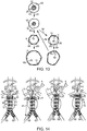
- a series of four images show the implantation of a stent 10 in the form of an AAA graph with an initial sub-optimal placement followed by adjusting the position of the stent to a more desired location as per the present disclosure.
- the sealing segment of stent 10 has only a small area of contact 64 with wall 61 inviting a potential endoleak into the aneurism.
- the first or left most image represents the stent 10 being deployed in a first arrangement 71 with wall 61 of passageway 60.
- stent 10 includes exactly one entrance opening 54 and two exit openings 55 corresponding to the iliac arteries.
- a minority 27 of length 28 of the fabric tub 26 can be considered to be a sealing segment 29.
- the physician may choose to use an electromagnetic field generator 4 to immerse stent 10 in an electromagnetic induction field 5 to generate heat in the induction responsive muscles 30 and cause the sealing segment 29 of the stent 10 to contract as shown in the second image from the left.
- the stent 10 may include induction responsive muscles 30 only in the region of the sealing segment 29 rather than throughout the stent as in the previously described versions.
- the deployment device 70 which is still connected to the stent 10, is utilized to maneuver the stent 10 for better placement as shown in the third image. Thereafter, the electromagnetic induction field may be terminated allowing the induction responsive muscles 30 in the sealing zone 29 to cool toward body temperature and move to their relaxed state 31 allowing the self expanding bias of the stent 10 to assume a second arrangement 72 with respect to the wall 61 of passageway 60 as shown in the far right image.
- the sealing segment 29 has a greater area of contacts 64 with the wall 61 of passageway 60 to better prevent endoleaks into the aneurism below. Thereafter, the remaining portions of the aortic aneurism treatment may continue in a manner known in the art.
- the procedure of immersing the stent in the electromagnetic induction field can be repeated, another adjustment can be made, and then the induction responsive muscles are allowed to cool. This procedure can be repeated any number of times until the stent 10 is satisfactorily positioned in the passageway 60.
- FIG. 15 three images showing a stent 10 according to the present disclosure deployed with ideal sealing in the first or left most image, and with unsatisfactory sealing in the second and third image due to the improper orientation of one end of the stent 10.
- the deployment device 70 may be used to adjust the orientation of the stent end toward the more ideal sealing configuration shown in the first image.
- This sequence is also of interest for showing that the stent 10, which may include a fabric tube covering 26, may have fenestrations 53 to accommodate openings into arteries in the aortic arch.
- stent 10 may include fenestrations 53 that should be positioned in registry with their associated arteries as part of the proper placement of stent 10 in the aortic arch.
- the present disclosure may be utilized to adjust the positioning of the fenestrations with regard to their respective arteries to achieve both ideal sealing and ideal positioning as per the first image.
- the stent 10 is initially moved in a contracted configuration ( Fig. 13 , first image) toward a deployment area 62 in a passageway 60.
- the stent 10 is changed from the contracted configuration 24 to a deployed configuration 25 in a first arrangement 71 with a wall 61 of the passageway 60, such as by withdrawing a sheath 74 that holds the stent 10 in a contracted configuration 24.
- the stent may be contracted from the deployed configuration 26 toward the contracted configuration 24 by immersing the stent 10 in an electromagnetic induction field 5. Thereafter, at least one of the orientation and position of the stent 10 is adjusted.
- the stent may be expanded back to the deployed configuration 25 in a second arrangement 72, which is different than the first arrangement 71, with the wall 61 of the passageway 60 by ceasing the immersion of the stent 10 in the electromagnetic induction field 5 to allow the induction responsive muscles 30 to cool toward body temperature to allow the self expanding bias of the stent to dominate its shape.
- the stent 10 is contracted by changing the induction responsive muscles 30 from the relaxed state 31 to the contracted state 32.
- the stent expands back to the deployed configuration 25 by changing the induction responsive muscles 30 from the contracted state 32 to the relaxed state 31 responsive to cooling due to the absence of the electromagnetic induction field 5.
- the temperature of the induction responsive muscles 30 increase responsive to immersion in the electromagnetic induction field 5.
- the adjustment of the position and/or orientation of the stent 10 may be performed by moving a deployment of device 70 that is connected to the stent. As shown, for instance in Figs. 9-11 , the adjustment may include merely adjusting an orientation of the stent 10. Also, the adjusting step may include changing the orientation of a sealing segment 29 of the stent as shown in Fig. 15 . Or, the adjustment that may include changing a positioning of the sealing segment 29 in the passageway 60 as shown, for instance in Fig. 14 . Also, the adjustment of the stent in general, and a sealing segment 29 in particular, may increase an area of contact between the sealing segment 29 and the wall of the passageway in the second arrangement 72 relative to the first arrangement 71.
- An electromagnetic field generator 4 for generating an electromagnetic induction fields according to the present disclosure is well known and need not be taught again here.
- the present disclosure teaches an induction heating strategy that allows the diameter of a stent to be reduced after the stent has initially been fully expanded.
- the physician can manipulate the stent 10 remotely, such as by using a deployment device, to readjust the stent's orientation, positioning or other irregularity (e.g. in-fold) if it initially landed sub-optimally.
- the strategy of the present disclosure may also be used to correct, for instance undesirable migration of a stent, as well as possibly assist in retracting a stent for removal from a patient.
- a stent which has a tubular shaped framework that includes a plurality of vertices that are each defined by a pair of struts.
- a plurality of induction responsive muscles are associated, respectively, with one of the plurality of vertices by being attached to the struts, for example to each strut of a pair of struts.
- the induction responsive muscles have a relaxed state at body temperatures, and have a contracted state at an elevated temperature greater than body temperature. If the stent has an initial unsatisfactory implant orientation or position or other expansion irregularity, the application of an electromagnetic induction field may be applied to temporarily reduce the diameter of the stent to adjust its positioning and/or orientation.
- the methods described herein may be applied to tissues of the human or animal body, it will be appreciated that such methods may not also be applied in other circumstances in which they do not provide any surgical or therapeutic effect. For example, such methods may be applied ex vivo, to tissue samples that are not part of the living human or animal body.
- the methods described herein may be practiced on meat, tissue samples, cadavers, and other non-living objects. Their implementation on cadavers may find particular utility in the training of surgeons and medical professionals. Methods which do not comprise treatment of the human or animal body by surgery or therapy have thus been disclosed.
- TITLE STENT WITH INDUCTION RESPONSIVE MUSCLES THAT FACILITATE IMPLANTATION ADJUSTMENTS
Applications Claiming Priority (1)
| Application Number | Priority Date | Filing Date | Title |
|---|---|---|---|
| US201762588992P | 2017-11-21 | 2017-11-21 |
Publications (1)
| Publication Number | Publication Date |
|---|---|
| EP3485847A1 true EP3485847A1 (fr) | 2019-05-22 |
Family
ID=64426801
Family Applications (1)
| Application Number | Title | Priority Date | Filing Date |
|---|---|---|---|
| EP18207621.6A Withdrawn EP3485847A1 (fr) | 2017-11-21 | 2018-11-21 | Stent à muscles réactifs à l'induction facilitant les ajustements d'implantation |
Country Status (2)
| Country | Link |
|---|---|
| US (1) | US10912664B2 (fr) |
| EP (1) | EP3485847A1 (fr) |
Cited By (14)
| Publication number | Priority date | Publication date | Assignee | Title |
|---|---|---|---|---|
| US10940001B2 (en) | 2012-05-30 | 2021-03-09 | Neovasc Tiara Inc. | Methods and apparatus for loading a prosthesis onto a delivery system |
| US11311376B2 (en) | 2019-06-20 | 2022-04-26 | Neovase Tiara Inc. | Low profile prosthetic mitral valve |
| US11357622B2 (en) | 2016-01-29 | 2022-06-14 | Neovase Tiara Inc. | Prosthetic valve for avoiding obstruction of outflow |
| US11389291B2 (en) | 2013-04-04 | 2022-07-19 | Neovase Tiara Inc. | Methods and apparatus for delivering a prosthetic valve to a beating heart |
| US11413139B2 (en) | 2011-11-23 | 2022-08-16 | Neovasc Tiara Inc. | Sequentially deployed transcatheter mitral valve prosthesis |
| US11419720B2 (en) | 2010-05-05 | 2022-08-23 | Neovasc Tiara Inc. | Transcatheter mitral valve prosthesis |
| US11464631B2 (en) | 2016-11-21 | 2022-10-11 | Neovasc Tiara Inc. | Methods and systems for rapid retraction of a transcatheter heart valve delivery system |
| US11491006B2 (en) | 2019-04-10 | 2022-11-08 | Neovasc Tiara Inc. | Prosthetic valve with natural blood flow |
| US11497602B2 (en) | 2012-02-14 | 2022-11-15 | Neovasc Tiara Inc. | Methods and apparatus for engaging a valve prosthesis with tissue |
| US11602429B2 (en) | 2019-04-01 | 2023-03-14 | Neovasc Tiara Inc. | Controllably deployable prosthetic valve |
| EP3982882A4 (fr) * | 2019-06-17 | 2023-07-05 | The Foundry, LLC | Dispositif hybride expansible |
| US11737872B2 (en) | 2018-11-08 | 2023-08-29 | Neovasc Tiara Inc. | Ventricular deployment of a transcatheter mitral valve prosthesis |
| US11779742B2 (en) | 2019-05-20 | 2023-10-10 | Neovasc Tiara Inc. | Introducer with hemostasis mechanism |
| US11793640B2 (en) | 2017-08-25 | 2023-10-24 | Neovasc Tiara Inc. | Sequentially deployed transcatheter mitral valve prosthesis |
Citations (3)
| Publication number | Priority date | Publication date | Assignee | Title |
|---|---|---|---|---|
| WO2011067764A1 (fr) * | 2009-12-02 | 2011-06-09 | Endospan Ltd. | Pose d'endoprothèse vasculaire fenêtrée |
| US20130331927A1 (en) * | 2007-01-19 | 2013-12-12 | Elixir Medical Corporation | Biodegradable endoprosthesis and methods for their fabrication |
| US9180005B1 (en) * | 2014-07-17 | 2015-11-10 | Millipede, Inc. | Adjustable endolumenal mitral valve ring |
Family Cites Families (23)
| Publication number | Priority date | Publication date | Assignee | Title |
|---|---|---|---|---|
| IL105828A (en) | 1993-05-28 | 1999-06-20 | Medinol Ltd | Medical stent |
| US6206888B1 (en) | 1997-10-01 | 2001-03-27 | Scimed Life Systems, Inc. | Stent delivery system using shape memory retraction |
| US6077298A (en) | 1999-02-20 | 2000-06-20 | Tu; Lily Chen | Expandable/retractable stent and methods thereof |
| US20020138134A1 (en) | 2000-12-29 | 2002-09-26 | Kim Young Kon | Thermostent for biomedical use |
| GB0322286D0 (en) | 2003-09-23 | 2003-10-22 | Angiomed Gmbh & Co | Implant with shape memory |
| JP4351560B2 (ja) | 2004-03-05 | 2009-10-28 | Necトーキン株式会社 | バルーン拡張超弾性ステント |
| EP1765221A1 (fr) | 2004-06-16 | 2007-03-28 | Cook Incorporated | Dispositif de deploiement thoracique et greffon de tuteur intravasculaire |
| WO2006072835A2 (fr) * | 2004-11-03 | 2006-07-13 | Jacques Seguin | Greffe vasculaire et systeme de deploiement |
| US20070073380A1 (en) | 2004-12-20 | 2007-03-29 | Vazquez Frank B | Longitudinally expanding, rotating & contracting shaped memory superelastic stent |
| WO2006086304A1 (fr) | 2005-02-08 | 2006-08-17 | Wilson-Cook Medical Inc. | Endoprothese vasculaire a contraction automatique |
| US20080004692A1 (en) | 2006-06-28 | 2008-01-03 | Henson Michael R | Dynamically adjustable vascular stent |
| US10004584B2 (en) * | 2006-07-10 | 2018-06-26 | First Quality Hygienic, Inc. | Resilient intravaginal device |
| US7771467B2 (en) * | 2006-11-03 | 2010-08-10 | The Cleveland Clinic Foundation | Apparatus for repairing the function of a native aortic valve |
| US9814611B2 (en) * | 2007-07-31 | 2017-11-14 | Edwards Lifesciences Cardiaq Llc | Actively controllable stent, stent graft, heart valve and method of controlling same |
| US9566178B2 (en) * | 2010-06-24 | 2017-02-14 | Edwards Lifesciences Cardiaq Llc | Actively controllable stent, stent graft, heart valve and method of controlling same |
| US8715334B2 (en) * | 2011-07-14 | 2014-05-06 | Boston Scientific Scimed, Inc. | Anti-migration stent with quill filaments |
| WO2013030818A2 (fr) * | 2011-08-28 | 2013-03-07 | Endospan Ltd. | Endoprothèses couvertes à déplacement axial et radial variable après déploiement |
| AU2013222451B2 (en) * | 2012-02-22 | 2018-08-09 | Edwards Lifesciences Cardiaq Llc | Actively controllable stent, stent graft, heart valve and method of controlling same |
| EP4166111A1 (fr) * | 2013-01-24 | 2023-04-19 | Cardiovalve Ltd. | Valvules prothétiques à ancrage ventriculaire |
| WO2017142874A2 (fr) * | 2016-02-16 | 2017-08-24 | Insera Therapeutics, Inc. | Dispositifs d'aspiration et dispositifs de déviation de flux ancrés |
| US20150073319A1 (en) | 2013-09-11 | 2015-03-12 | Massachusetts Institute Of Technology | Controllable Compression Textiles Using Shape Memory Alloys and Associated Products |
| CA2934975A1 (fr) * | 2013-11-11 | 2015-05-14 | Edwards Lifesciences Cardiaq Llc | Systemes et procede pour fabriquer une ossature d'endoprothese |
| GB201611910D0 (en) * | 2016-07-08 | 2016-08-24 | Valtech Cardio Ltd | Adjustable annuloplasty device with alternating peaks and troughs |
-
2018
- 2018-10-18 US US16/164,180 patent/US10912664B2/en active Active
- 2018-11-21 EP EP18207621.6A patent/EP3485847A1/fr not_active Withdrawn
Patent Citations (3)
| Publication number | Priority date | Publication date | Assignee | Title |
|---|---|---|---|---|
| US20130331927A1 (en) * | 2007-01-19 | 2013-12-12 | Elixir Medical Corporation | Biodegradable endoprosthesis and methods for their fabrication |
| WO2011067764A1 (fr) * | 2009-12-02 | 2011-06-09 | Endospan Ltd. | Pose d'endoprothèse vasculaire fenêtrée |
| US9180005B1 (en) * | 2014-07-17 | 2015-11-10 | Millipede, Inc. | Adjustable endolumenal mitral valve ring |
Cited By (17)
| Publication number | Priority date | Publication date | Assignee | Title |
|---|---|---|---|---|
| US11419720B2 (en) | 2010-05-05 | 2022-08-23 | Neovasc Tiara Inc. | Transcatheter mitral valve prosthesis |
| US11413139B2 (en) | 2011-11-23 | 2022-08-16 | Neovasc Tiara Inc. | Sequentially deployed transcatheter mitral valve prosthesis |
| US11497602B2 (en) | 2012-02-14 | 2022-11-15 | Neovasc Tiara Inc. | Methods and apparatus for engaging a valve prosthesis with tissue |
| US11389294B2 (en) | 2012-05-30 | 2022-07-19 | Neovasc Tiara Inc. | Methods and apparatus for loading a prosthesis onto a delivery system |
| US10940001B2 (en) | 2012-05-30 | 2021-03-09 | Neovasc Tiara Inc. | Methods and apparatus for loading a prosthesis onto a delivery system |
| US11617650B2 (en) | 2012-05-30 | 2023-04-04 | Neovasc Tiara Inc. | Methods and apparatus for loading a prosthesis onto a delivery system |
| US11389291B2 (en) | 2013-04-04 | 2022-07-19 | Neovase Tiara Inc. | Methods and apparatus for delivering a prosthetic valve to a beating heart |
| US11357622B2 (en) | 2016-01-29 | 2022-06-14 | Neovase Tiara Inc. | Prosthetic valve for avoiding obstruction of outflow |
| US11464631B2 (en) | 2016-11-21 | 2022-10-11 | Neovasc Tiara Inc. | Methods and systems for rapid retraction of a transcatheter heart valve delivery system |
| US11793640B2 (en) | 2017-08-25 | 2023-10-24 | Neovasc Tiara Inc. | Sequentially deployed transcatheter mitral valve prosthesis |
| US11737872B2 (en) | 2018-11-08 | 2023-08-29 | Neovasc Tiara Inc. | Ventricular deployment of a transcatheter mitral valve prosthesis |
| US11602429B2 (en) | 2019-04-01 | 2023-03-14 | Neovasc Tiara Inc. | Controllably deployable prosthetic valve |
| US11491006B2 (en) | 2019-04-10 | 2022-11-08 | Neovasc Tiara Inc. | Prosthetic valve with natural blood flow |
| US11779742B2 (en) | 2019-05-20 | 2023-10-10 | Neovasc Tiara Inc. | Introducer with hemostasis mechanism |
| EP3982882A4 (fr) * | 2019-06-17 | 2023-07-05 | The Foundry, LLC | Dispositif hybride expansible |
| US11311376B2 (en) | 2019-06-20 | 2022-04-26 | Neovase Tiara Inc. | Low profile prosthetic mitral valve |
| US11931254B2 (en) | 2019-06-20 | 2024-03-19 | Neovasc Tiara Inc. | Low profile prosthetic mitral valve |
Also Published As
| Publication number | Publication date |
|---|---|
| US20190151122A1 (en) | 2019-05-23 |
| US10912664B2 (en) | 2021-02-09 |
Similar Documents
| Publication | Publication Date | Title |
|---|---|---|
| EP3485847A1 (fr) | Stent à muscles réactifs à l'induction facilitant les ajustements d'implantation | |
| US10898320B2 (en) | Devices, systems and methods for delivering a prosthetic mitral valve and anchoring device | |
| CN107635513B (zh) | 植入管、用于植入其的系统以及设置和推送其的方法 | |
| US9060853B2 (en) | Stent and stent-graft designs | |
| US9572652B2 (en) | Modular endograft devices and associated systems and methods | |
| KR100580781B1 (ko) | 관내 대동맥 스텐트 | |
| JP2022180591A (ja) | 個人に合わせて調整されたプロテーゼおよび展開の方法 | |
| JP2020508086A (ja) | シースが収縮されたステントグラフト送達システムおよび使用方法 | |
| US20080065205A1 (en) | Retrievable implant and method for treatment of mitral regurgitation | |
| US20050177228A1 (en) | Device for changing the shape of the mitral annulus | |
| US10792149B2 (en) | Expandable stent and methods of crimping and expanding such stent | |
| US20110166640A1 (en) | Stent having less invasive ends and improved radial force | |
| KR101996742B1 (ko) | 체조직에 기구를 고정시키기 위한 마이크로앵커 | |
| US20190015104A1 (en) | Connector and method for coupling anatomical walls | |
| US10117736B2 (en) | Low radial force filter | |
| US20230363886A1 (en) | Stent graft systems with restraints in channels and methods thereof | |
| JP2024501398A (ja) | 弁輪形成装置 | |
| Hopkinson | Improved endograft fixation—a role for aortic endostapling? |
Legal Events
| Date | Code | Title | Description |
|---|---|---|---|
| PUAI | Public reference made under article 153(3) epc to a published international application that has entered the european phase |
Free format text: ORIGINAL CODE: 0009012 |
|
| AK | Designated contracting states |
Kind code of ref document: A1 Designated state(s): AL AT BE BG CH CY CZ DE DK EE ES FI FR GB GR HR HU IE IS IT LI LT LU LV MC MK MT NL NO PL PT RO RS SE SI SK SM TR |
|
| AX | Request for extension of the european patent |
Extension state: BA ME |
|
| 17P | Request for examination filed |
Effective date: 20191112 |
|
| RBV | Designated contracting states (corrected) |
Designated state(s): AL AT BE BG CH CY CZ DE DK EE ES FI FR GB GR HR HU IE IS IT LI LT LU LV MC MK MT NL NO PL PT RO RS SE SI SK SM TR |
|
| GRAP | Despatch of communication of intention to grant a patent |
Free format text: ORIGINAL CODE: EPIDOSNIGR1 |
|
| INTG | Intention to grant announced |
Effective date: 20191220 |
|
| RAP1 | Party data changed (applicant data changed or rights of an application transferred) |
Owner name: COOK MEDICAL TECHNOLOGIES LLC |
|
| STAA | Information on the status of an ep patent application or granted ep patent |
Free format text: STATUS: THE APPLICATION IS DEEMED TO BE WITHDRAWN |
|
| 18D | Application deemed to be withdrawn |
Effective date: 20200603 |