EP3485355B1 - Finger-mounted device with sensors and haptics - Google Patents
Finger-mounted device with sensors and haptics Download PDFInfo
- Publication number
- EP3485355B1 EP3485355B1 EP18740433.0A EP18740433A EP3485355B1 EP 3485355 B1 EP3485355 B1 EP 3485355B1 EP 18740433 A EP18740433 A EP 18740433A EP 3485355 B1 EP3485355 B1 EP 3485355B1
- Authority
- EP
- European Patent Office
- Prior art keywords
- finger
- user
- mounted device
- haptic output
- input
- Prior art date
- Legal status (The legal status is an assumption and is not a legal conclusion. Google has not performed a legal analysis and makes no representation as to the accuracy of the status listed.)
- Active
Links
Images





Classifications
-
- G—PHYSICS
- G01—MEASURING; TESTING
- G01L—MEASURING FORCE, STRESS, TORQUE, WORK, MECHANICAL POWER, MECHANICAL EFFICIENCY, OR FLUID PRESSURE
- G01L1/00—Measuring force or stress, in general
- G01L1/14—Measuring force or stress, in general by measuring variations in capacitance or inductance of electrical elements, e.g. by measuring variations of frequency of electrical oscillators
-
- G—PHYSICS
- G01—MEASURING; TESTING
- G01L—MEASURING FORCE, STRESS, TORQUE, WORK, MECHANICAL POWER, MECHANICAL EFFICIENCY, OR FLUID PRESSURE
- G01L1/00—Measuring force or stress, in general
- G01L1/16—Measuring force or stress, in general using properties of piezoelectric devices
-
- G—PHYSICS
- G01—MEASURING; TESTING
- G01P—MEASURING LINEAR OR ANGULAR SPEED, ACCELERATION, DECELERATION, OR SHOCK; INDICATING PRESENCE, ABSENCE, OR DIRECTION, OF MOVEMENT
- G01P15/00—Measuring acceleration; Measuring deceleration; Measuring shock, i.e. sudden change of acceleration
-
- G—PHYSICS
- G01—MEASURING; TESTING
- G01P—MEASURING LINEAR OR ANGULAR SPEED, ACCELERATION, DECELERATION, OR SHOCK; INDICATING PRESENCE, ABSENCE, OR DIRECTION, OF MOVEMENT
- G01P15/00—Measuring acceleration; Measuring deceleration; Measuring shock, i.e. sudden change of acceleration
- G01P15/003—Kinematic accelerometers, i.e. measuring acceleration in relation to an external reference frame, e.g. Ferratis accelerometers
-
- G—PHYSICS
- G02—OPTICS
- G02B—OPTICAL ELEMENTS, SYSTEMS OR APPARATUS
- G02B27/00—Optical systems or apparatus not provided for by any of the groups G02B1/00 - G02B26/00, G02B30/00
- G02B27/01—Head-up displays
- G02B27/017—Head mounted
-
- G—PHYSICS
- G06—COMPUTING OR CALCULATING; COUNTING
- G06F—ELECTRIC DIGITAL DATA PROCESSING
- G06F3/00—Input arrangements for transferring data to be processed into a form capable of being handled by the computer; Output arrangements for transferring data from processing unit to output unit, e.g. interface arrangements
- G06F3/01—Input arrangements or combined input and output arrangements for interaction between user and computer
- G06F3/011—Arrangements for interaction with the human body, e.g. for user immersion in virtual reality
- G06F3/014—Hand-worn input/output arrangements, e.g. data gloves
-
- G—PHYSICS
- G06—COMPUTING OR CALCULATING; COUNTING
- G06F—ELECTRIC DIGITAL DATA PROCESSING
- G06F3/00—Input arrangements for transferring data to be processed into a form capable of being handled by the computer; Output arrangements for transferring data from processing unit to output unit, e.g. interface arrangements
- G06F3/01—Input arrangements or combined input and output arrangements for interaction between user and computer
- G06F3/016—Input arrangements with force or tactile feedback as computer generated output to the user
-
- G—PHYSICS
- G06—COMPUTING OR CALCULATING; COUNTING
- G06F—ELECTRIC DIGITAL DATA PROCESSING
- G06F3/00—Input arrangements for transferring data to be processed into a form capable of being handled by the computer; Output arrangements for transferring data from processing unit to output unit, e.g. interface arrangements
- G06F3/01—Input arrangements or combined input and output arrangements for interaction between user and computer
- G06F3/017—Gesture based interaction, e.g. based on a set of recognized hand gestures
-
- G—PHYSICS
- G06—COMPUTING OR CALCULATING; COUNTING
- G06F—ELECTRIC DIGITAL DATA PROCESSING
- G06F3/00—Input arrangements for transferring data to be processed into a form capable of being handled by the computer; Output arrangements for transferring data from processing unit to output unit, e.g. interface arrangements
- G06F3/01—Input arrangements or combined input and output arrangements for interaction between user and computer
- G06F3/03—Arrangements for converting the position or the displacement of a member into a coded form
- G06F3/033—Pointing devices displaced or positioned by the user, e.g. mice, trackballs, pens or joysticks; Accessories therefor
- G06F3/0346—Pointing devices displaced or positioned by the user, e.g. mice, trackballs, pens or joysticks; Accessories therefor with detection of the device orientation or free movement in a three-dimensional [3D] space, e.g. 3D mice, 6-DOF [six degrees of freedom] pointers using gyroscopes, accelerometers or tilt-sensors
-
- G—PHYSICS
- G06—COMPUTING OR CALCULATING; COUNTING
- G06F—ELECTRIC DIGITAL DATA PROCESSING
- G06F3/00—Input arrangements for transferring data to be processed into a form capable of being handled by the computer; Output arrangements for transferring data from processing unit to output unit, e.g. interface arrangements
- G06F3/01—Input arrangements or combined input and output arrangements for interaction between user and computer
- G06F3/03—Arrangements for converting the position or the displacement of a member into a coded form
- G06F3/041—Digitisers, e.g. for touch screens or touch pads, characterised by the transducing means
- G06F3/042—Digitisers, e.g. for touch screens or touch pads, characterised by the transducing means by opto-electronic means
- G06F3/0421—Digitisers, e.g. for touch screens or touch pads, characterised by the transducing means by opto-electronic means by interrupting or reflecting a light beam, e.g. optical touch-screen
-
- G—PHYSICS
- G06—COMPUTING OR CALCULATING; COUNTING
- G06F—ELECTRIC DIGITAL DATA PROCESSING
- G06F3/00—Input arrangements for transferring data to be processed into a form capable of being handled by the computer; Output arrangements for transferring data from processing unit to output unit, e.g. interface arrangements
- G06F3/01—Input arrangements or combined input and output arrangements for interaction between user and computer
- G06F3/03—Arrangements for converting the position or the displacement of a member into a coded form
- G06F3/041—Digitisers, e.g. for touch screens or touch pads, characterised by the transducing means
- G06F3/042—Digitisers, e.g. for touch screens or touch pads, characterised by the transducing means by opto-electronic means
- G06F3/0425—Digitisers, e.g. for touch screens or touch pads, characterised by the transducing means by opto-electronic means using a single imaging device like a video camera for tracking the absolute position of a single or a plurality of objects with respect to an imaged reference surface, e.g. video camera imaging a display or a projection screen, a table or a wall surface, on which a computer generated image is displayed or projected
- G06F3/0426—Digitisers, e.g. for touch screens or touch pads, characterised by the transducing means by opto-electronic means using a single imaging device like a video camera for tracking the absolute position of a single or a plurality of objects with respect to an imaged reference surface, e.g. video camera imaging a display or a projection screen, a table or a wall surface, on which a computer generated image is displayed or projected tracking fingers with respect to a virtual keyboard projected or printed on the surface
-
- G—PHYSICS
- G06—COMPUTING OR CALCULATING; COUNTING
- G06F—ELECTRIC DIGITAL DATA PROCESSING
- G06F3/00—Input arrangements for transferring data to be processed into a form capable of being handled by the computer; Output arrangements for transferring data from processing unit to output unit, e.g. interface arrangements
- G06F3/01—Input arrangements or combined input and output arrangements for interaction between user and computer
- G06F3/048—Interaction techniques based on graphical user interfaces [GUI]
- G06F3/0481—Interaction techniques based on graphical user interfaces [GUI] based on specific properties of the displayed interaction object or a metaphor-based environment, e.g. interaction with desktop elements like windows or icons, or assisted by a cursor's changing behaviour or appearance
- G06F3/04815—Interaction with a metaphor-based environment or interaction object displayed as three-dimensional [3D], e.g. changing the user viewpoint with respect to the environment or object
-
- G—PHYSICS
- G06—COMPUTING OR CALCULATING; COUNTING
- G06F—ELECTRIC DIGITAL DATA PROCESSING
- G06F3/00—Input arrangements for transferring data to be processed into a form capable of being handled by the computer; Output arrangements for transferring data from processing unit to output unit, e.g. interface arrangements
- G06F3/01—Input arrangements or combined input and output arrangements for interaction between user and computer
- G06F3/048—Interaction techniques based on graphical user interfaces [GUI]
- G06F3/0487—Interaction techniques based on graphical user interfaces [GUI] using specific features provided by the input device, e.g. functions controlled by the rotation of a mouse with dual sensing arrangements, or of the nature of the input device, e.g. tap gestures based on pressure sensed by a digitiser
- G06F3/0488—Interaction techniques based on graphical user interfaces [GUI] using specific features provided by the input device, e.g. functions controlled by the rotation of a mouse with dual sensing arrangements, or of the nature of the input device, e.g. tap gestures based on pressure sensed by a digitiser using a touch-screen or digitiser, e.g. input of commands through traced gestures
- G06F3/04886—Interaction techniques based on graphical user interfaces [GUI] using specific features provided by the input device, e.g. functions controlled by the rotation of a mouse with dual sensing arrangements, or of the nature of the input device, e.g. tap gestures based on pressure sensed by a digitiser using a touch-screen or digitiser, e.g. input of commands through traced gestures by partitioning the display area of the touch-screen or the surface of the digitising tablet into independently controllable areas, e.g. virtual keyboards or menus
-
- G—PHYSICS
- G06—COMPUTING OR CALCULATING; COUNTING
- G06T—IMAGE DATA PROCESSING OR GENERATION, IN GENERAL
- G06T19/00—Manipulating three-dimensional [3D] models or images for computer graphics
- G06T19/006—Mixed reality
-
- G—PHYSICS
- G02—OPTICS
- G02B—OPTICAL ELEMENTS, SYSTEMS OR APPARATUS
- G02B27/00—Optical systems or apparatus not provided for by any of the groups G02B1/00 - G02B26/00, G02B30/00
- G02B27/01—Head-up displays
- G02B27/017—Head mounted
- G02B2027/0178—Eyeglass type
-
- G—PHYSICS
- G06—COMPUTING OR CALCULATING; COUNTING
- G06F—ELECTRIC DIGITAL DATA PROCESSING
- G06F2203/00—Indexing scheme relating to G06F3/00 - G06F3/048
- G06F2203/033—Indexing scheme relating to G06F3/033
- G06F2203/0331—Finger worn pointing device
Definitions
- This relates generally to electronic devices, and, more particularly, to wearable electronic devices.
- wearable devices to gather input for controlling electronic equipment can pose challenges. If care is not taken, a device such as a glove may affect the ability of a user to feel objects in the user's surroundings, may be uncomfortable to use, or may not gather suitable input from the user.
- US 2009/096746 A1 discloses a method and apparatus of using a wearable remote interface device capable of detecting inputs from movements.
- the wearable remote interface device which could be attached to a finger or a hand or any parts of a body, includes a sensor, a filter, an input identifier, and a transmitter.
- the sensor in one embodiment, is capable of sensing the movement of the finger or any part of body in which the wearable remote interface device is attached with.
- the filter Upon detecting the various movements associated with the finger, the filter subsequently removes any extraneous gestures from the detected movements.
- the input identifier which could be a part of the filter, identifies one or more user inputs from the filtered movements.
- the transmitter transmits the input(s) to a processing device via a wireless communications network.
- US 2005/052412 A1 discloses a computer or video game device for generating hand manipulated data.
- the device consists of one or more sensors that are mounted on the human hand. The sensors are conveniently located for easy access and manipulation by opposing fingers on the same hand that the sensors are mounted on. This arrangement overcomes the limitations of a tabletop computer mouse by not requiring a planar surface, and by not requiring the user to hold onto the device.
- the sensors are located in such a way that they do not impede standard office procedures such as using a computer keyboard, writing with a pen, holding a phone, etcetera.
- the device can also be quickly and easily attached or removed by the user.
- Various embodiments of the invention include "wired”, “wireless”, multiple finger, universal right or left-hand, universal finger or thumb application, and universal side or top mounted sensors. Existing technologies and manufacturing techniques are utilized to minimize cost. Uses include personal computer, video game, and industrial applications.
- US 2016/313798 A1 discloses an invention that can be embodied in a wearable device or system for measuring finger motion and recognizing hand gestures comprising a distal loop which encircles the intermediate phalanx of a finger, a proximal loop which encircles the proximal phalanx of the finger, a joint-spanning strip which connects these two loops, and a bend sensor which is part of the joint-spanning strip. Changes in energy transmitted through, or generated by, the bend sensor are used to measure the motion and/or configuration of the proximal interphalangeal joint.
- JP2001104256A relates to enabling measurement of finger touch pressure without attaching sensor on the touched surface or losing sense of touching by providing a strain gauge attached to the distorted body.
- US2007030246A1 relates to a tactile feedback man-machine interface device which provides tactile feedback to various sensing body parts.
- WO 2012/176610 A1 discloses a finger stimulus presentation device capable of imparting a mechanical stimulus to a finger while mounted thereon and minimizing loss to the usability of the finger.
- a finger-mounted device may include finger-mounted units coupled to control circuitry.
- the control circuitry wirelessly transmit information gathered with the finger mounted units to an external device to control the external device.
- the control circuitry also use the finger-mounted units to provide a user's fingers with feedback such as haptic feedback.
- the control circuitry may supply haptic output to a user's fingers based on wirelessly received information from the external device.
- the haptic output may correspond to virtual reality or augmented reality haptic output.
- the finger-mounted units each have a body.
- the body serves as a support structure for components such as force sensors, accelerometers, and other sensors and for haptic output devices.
- a user may wear the finger mounted units on the tips of the user's fingers while interacting with external objects.
- each finger-mounted unit have sidewall portions coupled by portion that rests adjacent to a user's fingernail. A user's fingertip may be received between the sidewall portions.
- the body may be formed from deformable material such as metal or may be formed from adjustable structures such as sliding body portions that are coupled to each other using magnetic attraction, springs, or other structures. This allows the body of the finger-mounted unit to be adjusted to accommodate different finger sizes.
- each finger-mounted unit have a U-shaped cross-sectional profile that leaves the finger pad of each finger exposed when the body is coupled to a fingertip of a user's finger.
- the control circuitry may gather lateral finger movement input using the sensors and mag provide haptic output using the haptic output device.
- Wearable electronic devices may be used to gather input from a user and may be used to provide haptic output or other output to the user.
- a wearable device such as a finger-mounted device may be used to gather input from a user's fingers as the user interacts with surfaces in the user's environment and may be used to provide clicks and other haptic output during these interactions.
- the input that is gathered in this way may include information on how firmly a user is pressing against objects (finger press input), finger tap input associated with light taps of a user's finger against a surface, lateral finger movement information such as shear force information indicating how firmly a user is pressing their finger sideways on a surface, and other user input.
- FIG. 16 shows how sidewall portions of unit 22 may have a rotatable flap such as flaps 40P or 40P'.
- the flap may rotate into position 40F (e.g., a position in which a haptic output device or other component 56 is adjacent to finger pad 48).
- FIG. 29 is a diagram showing how visual elements can be manipulated by a user who is wearing finger-mounted device 22 on finger 32.
- Visual elements such as illustrative element 76 (e.g., an icon representing a desktop application, a file folder, a media file or other file, or other information) may be displayed using a display in device 20.
- Workspace 74 may have markers 72, if desired.
- a user may select visual items using taps, force input, persistent touch input, air gestures, and/or other user input that is detected using unit(s) 22 and/or other equipment in system 12 such as cameras in device 20.
- the user may contact a table surface or other surface with the surface of finger 32.
- the finger pulp of finger pad 48 at the bottom of the tip of finger 32 may contact the table surface and may be compressed by the force imparted by finger 32.
- the forces imposed on a user's fingers as the user is providing input to an electronic device can be modified using components coupled to a user's finger and/or components in the electronic device.
- components in a finger-mounted device such as unit 22 may be used to help soften the impact between a user's finger and the input surface (e.g., a surface associated with workspace 74).
- FIG. 30 shows how visual element 76 may be a list containing multiple items.
- a desired item in the list may be selected by causing finger 32 to hover (linger) over the desired item for more than a predetermined amount of time (as shown by illustrative selected item 76H).
- Finger position information gathered by system 10 e.g., an inertial measurement in unit 22, a camera measuring a marker on a unit 22, etc.
- Gestures may be used to scroll through items.
- system 10 can detect the position of units 22 using optical sensing.
- units 22 may include visual markers 72 (e.g., passive markers, visible or infrared light-emitting diodes, etc.). Markers 72 may be placed on portions of unit 22 in device 10 such as portions 42 and 40. Markers 72 may be arranged in a recognizable asymmetrical pattern to help avoid creating ambiguous position data.
- visual markers 72 e.g., passive markers, visible or infrared light-emitting diodes, etc.
- thinner portion 42T and/or other portions of unit 22 may be formed from components with adjustable flexibility.
- An illustrative component with adjustable flexibility is shown in FIG. 33 .
- component 80 e.g., a layer with an electrically adjustable flexibility
- layers 82 can slip with respect to each other and component 80 can flex.
- layers 82 will lock into place and component 80 will not be flexible.
- Component 80 may be located in portion 42T of unit 22 of FIG. 32 .
- portion 42T can bend, allowing unit 22 to be placed over a user's finger. After placing unit 22 on a user's finger, unit 22 can be locked in place on the finger by applying a control signal to electrodes 84.
Landscapes
- Engineering & Computer Science (AREA)
- General Engineering & Computer Science (AREA)
- Theoretical Computer Science (AREA)
- Physics & Mathematics (AREA)
- General Physics & Mathematics (AREA)
- Human Computer Interaction (AREA)
- Software Systems (AREA)
- Computer Graphics (AREA)
- Computer Hardware Design (AREA)
- Optics & Photonics (AREA)
- Multimedia (AREA)
- User Interface Of Digital Computer (AREA)
- Position Input By Displaying (AREA)
Description
- This relates generally to electronic devices, and, more particularly, to wearable electronic devices.
- Electronic equipment such as computers and head-mounted display systems are sometimes controlled using input-output devices such as gloves. A glove may have sensors that detect user hand motions. The user hand motions can be used in controlling electronic equipment.
- The use of wearable devices to gather input for controlling electronic equipment can pose challenges. If care is not taken, a device such as a glove may affect the ability of a user to feel objects in the user's surroundings, may be uncomfortable to use, or may not gather suitable input from the user.
US 2009/096746 A1 discloses a method and apparatus of using a wearable remote interface device capable of detecting inputs from movements. The wearable remote interface device, which could be attached to a finger or a hand or any parts of a body, includes a sensor, a filter, an input identifier, and a transmitter. The sensor, in one embodiment, is capable of sensing the movement of the finger or any part of body in which the wearable remote interface device is attached with. Upon detecting the various movements associated with the finger, the filter subsequently removes any extraneous gestures from the detected movements. The input identifier, which could be a part of the filter, identifies one or more user inputs from the filtered movements. The transmitter transmits the input(s) to a processing device via a wireless communications network.
US 2005/052412 A1 discloses a computer or video game device for generating hand manipulated data. The device consists of one or more sensors that are mounted on the human hand. The sensors are conveniently located for easy access and manipulation by opposing fingers on the same hand that the sensors are mounted on. This arrangement overcomes the limitations of a tabletop computer mouse by not requiring a planar surface, and by not requiring the user to hold onto the device. Additionally, the sensors are located in such a way that they do not impede standard office procedures such as using a computer keyboard, writing with a pen, holding a phone, etcetera. The device can also be quickly and easily attached or removed by the user. Various embodiments of the invention include "wired", "wireless", multiple finger, universal right or left-hand, universal finger or thumb application, and universal side or top mounted sensors. Existing technologies and manufacturing techniques are utilized to minimize cost. Uses include personal computer, video game, and industrial applications.US 2016/313798 A1 discloses an invention that can be embodied in a wearable device or system for measuring finger motion and recognizing hand gestures comprising a distal loop which encircles the intermediate phalanx of a finger, a proximal loop which encircles the proximal phalanx of the finger, a joint-spanning strip which connects these two loops, and a bend sensor which is part of the joint-spanning strip. Changes in energy transmitted through, or generated by, the bend sensor are used to measure the motion and/or configuration of the proximal interphalangeal joint.
JP2001104256A
US2007030246A1 relates to a tactile feedback man-machine interface device which provides tactile feedback to various sensing body parts.
WO 2012/176610 A1 discloses a finger stimulus presentation device capable of imparting a mechanical stimulus to a finger while mounted thereon and minimizing loss to the usability of the finger. - A finger-mounted device may include finger-mounted units coupled to control circuitry. The control circuitry wirelessly transmit information gathered with the finger mounted units to an external device to control the external device. The control circuitry also use the finger-mounted units to provide a user's fingers with feedback such as haptic feedback. For example, the control circuitry may supply haptic output to a user's fingers based on wirelessly received information from the external device. The haptic output may correspond to virtual reality or augmented reality haptic output.
- The finger-mounted units each have a body. The body serves as a support structure for components such as force sensors, accelerometers, and other sensors and for haptic output devices. During operation, a user may wear the finger mounted units on the tips of the user's fingers while interacting with external objects.
- The body of each finger-mounted unit have sidewall portions coupled by portion that rests adjacent to a user's fingernail. A user's fingertip may be received between the sidewall portions. The body may be formed from deformable material such as metal or may be formed from adjustable structures such as sliding body portions that are coupled to each other using magnetic attraction, springs, or other structures. This allows the body of the finger-mounted unit to be adjusted to accommodate different finger sizes.
- The body of each finger-mounted unit have a U-shaped cross-sectional profile that leaves the finger pad of each finger exposed when the body is coupled to a fingertip of a user's finger. The control circuitry may gather lateral finger movement input using the sensors and mag provide haptic output using the haptic output device.
The present invention is described by the independent claims and the preferred embodiments are described in the dependent claims. -
-
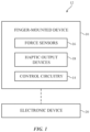
FIG. 1 is a schematic diagram of an illustrative device such as a finger-mounted device. -
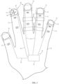
FIG. 2 is top view of a user's hand and illustrative finger-mounted device components on finger tips of the user's hand. -
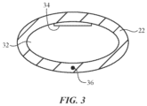
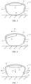
FIG. 3 is a cross-sectional view of an illustrative finger-mounted device on a user's finger. -
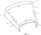
FIG. 4 is a perspective view of an illustrative finger-mounted device. -
FIGS. 5, 6, and 7 are illustrative views of the tip of a user's finger during use of a finger-mounted device. -
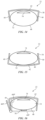
FIG. 8 is a cross-sectional view of an illustrative finger-mounted device. -
FIG. 9 is a side view of an illustrative finger-mounted device . -
FIG. 10 is a top view of an illustrative finger-mounted device . -
FIG. 11 is a cross-sectional side view of an illustrative piezoelectric beam device. -
FIG. 12 is a cross-sectional side view of an illustrative piezoelectric disk device. -
FIG. 13 a cross-sectional side view of an illustrative capacitive force sensor. -
FIGS. 14, 15, and 16 are views showing illustrative mounting arrangements for finger-mounted devices. -
FIG. 17 is a graph of illustrative haptic output drive signals that may be provided to a haptic output device in a finger-mounted device. -
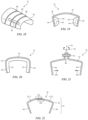
FIG. 18 is a perspective view of an illustrative finger-mounted unit with wires that form elongated frame structures spanning the width of the unit. -
FIG. 19 is a view of an illustrative finger-mounted unit with pneumatically actuated finger grippers . -
FIG. 20 is a view of an illustrative finger-mounted device having a body member lined with a compressible material such as foam or elastomeric polymer. -
FIG. 21 is a view of an illustrative finger-mounted device with an adjustable screw that controls the width of the body of the finger-mounted device. -
FIG. 22 is a view of an illustrative finger-mounted device with sliding body members that are coupled to each other by magnetic attraction. -
FIG. 23 is a view of an illustrative finger-mounted device with a spring to adjust the width of the body of the device. -
FIG. 24 is a view of an illustrative finger-mounted device with a deformable body. -
FIG. 25 is a cross-sectional side view of an illustrative polymer-coated deformable metal body member for a finger-mounted device. -
FIG. 26 is a side view of an illustrative finger-mounted device being worn on a finger at a location other than the tip of the finger. -
FIG. 27 is a side view of an illustrative finger-mounted device with optical sensors for gathering touch input from the upper surface of a user's finger. -
FIG. 28 is a diagram showing how markers may be used in calibrating a system in which a finger-mounted device is used in accordance with an embodiment. -
FIG. 29 is a diagram showing how visual elements can be manipulated by a user who is wearing a finger-mounted device. -
FIG. 30 is a diagram in which a user is selecting an item in a list using a finger-mounted device. -
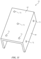
FIG. 31 is a perspective view of an illustrative finger-mounted device with visual markers. -
FIG. 32 is a cross-sectional view of an illustrative finger-mounted device with a thinned central region. -
FIG. 33 is an illustrative layer with an electrically adjustable flexibility for use in securing a finger-mounted device to a user's finger. - Wearable electronic devices may be used to gather input from a user and may be used to provide haptic output or other output to the user. For example, a wearable device such as a finger-mounted device may be used to gather input from a user's fingers as the user interacts with surfaces in the user's environment and may be used to provide clicks and other haptic output during these interactions. The input that is gathered in this way may include information on how firmly a user is pressing against objects (finger press input), finger tap input associated with light taps of a user's finger against a surface, lateral finger movement information such as shear force information indicating how firmly a user is pressing their finger sideways on a surface, and other user input. Haptic output may be provided to the user to confirm to the user that a light tap input has been recognized or to otherwise provide feedback to the user. The haptic feedback may provide the user with a sensation of tapping on a physical keyboard or other input device with a movable button member even when the user is tapping on a hard flat surface such as a tabletop. The haptic output provided with the wearable electronic device to the user may be virtual reality haptic output or augmented reality haptic output that is provided while a user is wearing a head-mounted display or other device that creates a virtual reality or augmented reality environment for a user.
- To allow the user to feel real-world objects accurately, the finger-mounted device may have a U-shaped cross-sectional profile or other shape that allows underside portions of the user's fingertips to be exposed to the environment. Sensor components for the finger-mounted device may be formed from force sensors, optical sensors, and other sensors. Haptic output devices may include piezoelectric actuators and other components that provide haptic output. In some configurations, a piezoelectric device or other component may be used both to provide haptic output (when driven with an output signal) and to gather force sensor input.
- A finger-mounted device may be used to control a virtual reality or augmented reality system, may provide a user with the sensation of interacting on a physical keyboard when the user is making finger taps on a table surface (e.g., a virtual keyboard surface that is being displayed in alignment with the table surface using a head-mounted display), may allow a user to supply joystick-type input using only lateral movement of the user's fingertips, may gather force sensor measurements (user finger press force measurements) that are used in controlling other equipment, and/or may be used in gathering input and providing a user with haptic output in other system environments.
-
FIG. 1 is a diagram of an illustrative system that includes a wearable device such as a finger-mounted device. As shown inFIG. 1 ,system 12 may include a finger-mounted device such asdevice 10 that interacts with electronic equipment such aselectronic device 20. Finger-mounteddevice 10 may include sensors such asforce sensors 16,haptic output devices 18, andcontrol circuitry 14. Components such as these may be mounted on the body parts of a user (e.g., on a user's fingertips) using housing structures (sometimes referred to as body structures or body members). Housing structures may be formed for portions ofdevice 10 that reside on one or more fingers. For example,device 10 may include a separate body member and associated components for each of multiple different fingers of a user. The housing structures may be formed from metal, polymer, fabric, glass, ceramic, other materials, or combinations of these materials. In some configurations, wireless or wired links may be used to route signals to and from fingertip components to other portions of device 10 (e.g., a portion ofdevice 10 that is located on the rear of a user's hand, etc.). - If desired,
device 10 may include input-output devices other thanforce sensors 14. For example,device 10 may include optical sensors (e.g., sensors that detect light or sensors that emit light and detect reflected light), image sensors, status indicator lights and displays (e.g., light-based components such as light-emitting diodes that emit one or more regions of light, pixel arrays for displaying images, text, and graphics, etc.), may include buttons (e.g., power buttons and other control buttons), audio components (e.g., microphones, speakers, tone generators, etc.), touch sensors, sensors for detecting position, orientation, and/or motion (e.g., accelerometers, magnetic sensors such as compass sensors, gyroscopes, inertial measurement units that contain some or all of these sensors), muscle activity sensors (EMG) for detecting finger actions, and/or other circuitry for gathering input. -
Haptic output devices 18 may be electromagnetic actuators (e.g., vibrators, linear solenoids, etc.), may be piezoelectric devices (e.g., piezoelectric devices that are separate from force sensing piezoelectric devices indevice 10 and/or piezoelectric devices that serve both as haptic output devices and as force sensors), may be components that produce haptic output using heat-induced physical changes (e.g., by heating shape memory alloys), may be electroactive polymer components, or may be other suitable components that produce haptic output. -
Control circuitry 14 may include storage and processing circuitry for supporting the operation ofdevice 10. The storage and processing circuitry may include storage such as nonvolatile memory (e.g., flash memory or other electrically-programmable-read-only memory configured to form a solid state drive), volatile memory (e.g., static or dynamic random-access-memory), etc. Processing circuitry incontrol circuitry 14 may be used to gather input from sensors and other input devices and may be used to control output devices such ashaptic output devices 18. The processing circuitry may be based on one or more microprocessors, microcontrollers, digital signal processors, baseband processors and other wireless communications circuits, power management units, audio chips, application specific integrated circuits, etc. -
Control circuitry 14 may include antennas, radio-frequency transceiver circuitry, and other wireless communications circuitry and/or wired communications circuitry to support communications with external equipment such aselectronic device 20.Control circuitry 14 may, for example, support bidirectional communications withdevice 20 over a wireless local area network link, a cellular telephone link, or other suitable wired or wireless communications link (e.g., a Bluetooth® link, a WiFi® link, a 60 GHz link, etc.).Device 20 may be, for example, a tablet computer, a desktop computer, a cellular telephone, a head-mounted device such as a head-mounted display, wearable equipment, a wrist watch device, a set-top box, a gaming unit, a television, a display that is coupled to a desktop computer or other electronic equipment, a voice-controlled speaker, home automation equipment, an accessory (e.g., ear buds, a removable case for a portable device, etc.), or other electronic equipment.Device 20 may include input-output circuitry such as sensors, buttons, cameras, displays, and other input-output devices and may include control circuitry (e.g., control circuitry such as control circuitry 14) for controlling the operation ofdevice 20.Control circuitry 14 may include wireless power circuitry (e.g., a coil and rectifier for receiving wirelessly transmitted power from a wireless power transmitting device that has a corresponding wireless power transmitting circuit with a coil). During wireless power transmission operations (e.g., inductive power transmission), wireless power may be provided todevice 20 and distributed to load circuitry in device 20 (e.g.,circuitry 14,devices 18,sensors 16, etc.).Circuitry 14 may include energy storage circuitry (e.g., batteries and/or capacitors) for storing power from a wired power device and/or a wireless power transmitting device. -
Device 20 may be coupled to one or more additional devices insystem 12. For example, a head-mounted device with a display may be used for displaying visual content (virtual reality content and/or augmented reality content) to a user. This head-mounted device may be coupled to an electronic device such as a cellular telephone, tablet computer, laptop computer, or other equipment using wired and/or wireless communications links.Devices 20 may communicate withdevice 10 to gather input (e.g., user finger position information) and to provide output (e.g., using haptic output components in device). - During operation,
control circuitry 14 ofdevice 10 use communications circuitry to transmit user input such as force sensor information and information from other sensors todevice 20 to use in controllingdevice 20. Information from the sensors and other input devices indevice 10 and/or information fromdevice 20 may be used bycontrol circuitry 14 in determining the strength and duration of haptic output supplied to the user withhaptic output devices 18. -
FIG. 2 is top view of a user's hand and an illustrative finger-mounted device. As shown inFIG. 2 ,device 10 may be formed from one or more finger-mountedunits 22 mounted onfingers 32 of the user.Units 22 may, for example, be mounted on the tips of fingers 32 (e.g., overlapping fingernails 34). Some or all ofcontrol circuitry 14 may be contained inunits 22 or may be mounted in separate housing structures (e.g., part of a wrist band, a glove, a partial glove such as a fingerless glove or glove in which portions have been removed under the pads of a user's finger tips, etc.). Signal paths such assignal paths 24 may be used in interconnecting the circuitry ofunits 22 and/or additional circuitry such ascontrol circuitry 14 that is located out ofunits 22. -
Signal paths 24 may include wired or wireless links. Wired paths may be formed, for example, using metal traces on a printed circuit such as a flexible printed circuit, using wires, using conductive strands (e.g. wires or metal-coated polymer strands) in woven, knit, or braided fabric, and/or using other conductive signal lines. In configurations in which some or all ofcontrol circuitry 14 is located outside ofunits 22, signal paths such assignal paths 24 may run across some or all of user'shand 30 to couple the circuitry ofunits 22 to this control circuitry. Configuration in which controlcircuitry 10 is located in one ormore units 22 and in which theseunits 22 are interconnected by wired orwireless paths 24 may also be used, if desired. - When
units 22 are located on the user's fingertips, components inunits 22 may sense contact between the user's fingertips and external surfaces. In some configurations, a user's fingertip (e.g., the pad of the user's fingertip) may contact a surface and, while the fingertip is in contact with the surface, a user may move the fingertip laterally in lateral directions such aslateral directions FIG. 2 . The lateral movement of the fingertip while the pad of the fingertip is in contact with a surface (e.g., movement of the fingertip in dimensions parallel to the plane of the surface being contacted) may generate shear forces that can be detected by the components of one ormore units 22. This allows the user's own fingertip to be used as a pointing device (e.g. to be used as a joystick) that can control an on-screen cursor or other adjustable system feature in a device such asdevice 20 ofFIG. 1 . In some configurations,units 22 may be worn on portions ofhand 30 other than the fingertips offingers 32. For example,units 22 may be worn elsewhere along the lengths offingers 32, as shown by illustrative units 22' ofFIG. 2 . If desired,units 22 and 22' may be used together in device 10 (e.g., to gather information from multiple finger locations). Illustrative configuration in whichunits 22 are mounted at the tips offingers 32 may sometimes be described herein as an example. -
Units 22 may partly or completely surround the tips offingers 32.FIG. 3 is a cross-sectional view of an illustrative finger-mounted device (unit 22) on a user'sfinger 32 in an arrangement in which the body ofunit 22 surrounds finger 32 (e.g., in whichunit 22 has portions of the top, sides, and lower finger pad portion of finger 32).Unit 22 ofFIG. 3 may, as an example, be formed from a soft elastomeric material, fabric, or other flexible material that allows the user to feel surfaces throughunit 22. If desired, sensors, haptic devices, and or other components may be mounted under the pad offinger 32 in locations such aslocation 36. - If desired,
units 22 may have a U-shaped cross-sectional profile so thatunits 22 cover only the tops and/or sides of the user's fingers while the pads of the user's fingertips are exposed and not covered by any portions ofdevice 10.Units 22 with this type of configuration may allow the user to touch surfaces with the user's own skin, thereby enhancing the user's sensitivity to the environment in whichdevice 10 is being used. For example,units 22 that cover only the tops and sides of a user's fingertips may allow the pads of the user's finger to detect small surface imperfections on a touched surface, slight irregularities in surface texture, and other details that might be obscured in a configuration in which the pads of the user's fingers are covered. -
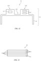
FIG. 4 is a perspective view of anillustrative unit 22 for finger-mounteddevice 10 in whichbody 38 ofunit 22 is configured to only partly surround a user's fingertip. As shown inFIG. 4 ,body 38 include side portions such as sidewall portions 40 (e.g., portions that contact the sides of a user's finger) and portions such as coupling portion 42 (e.g., a slightly bowed portion that covers the top of a user's fingertip or, in some configurations, that covers the pad of the user's fingertip at the bottom of the user's fingertip).Potion 42 may supportsidewall portions 40 adjacent to opposing left and right sides of a user's finger. Openings such asoptional openings 44 may be formed inbody 38 to facilitate bending of a metal member or otherstructure forming body 38.Body 38 may be tapered to facilitate mounting ofbody 38 on a user's fingertip (e.g.,body 38 may have a wider portion of width W1 and a narrower portion for the outermost tip of the user's finger with a width W2 that is less than W1). -
FIG. 5 is an end view of an illustrative unit such asunit 22 ofFIG. 5 in a configuration in which a user's finger (e.g.,finger pad 48 at the bottom of the tip of finger 32) is resting lightly on an external surface such assurface 46. As shown inFIG. 5 ,body 38 ofunit 22 may have a U-shaped cross-sectional profile that holdsbody 38 tofinger 32 with a friction fit. With this configuration, the open side ofU-shaped body 38 may face downward to exposefinger pad 48. - When a user moves
finger 32 laterally indirection 50 as shown inFIG. 6 , shear forces are generated. Force sensors (e.g., in sidewalls 40) detects this shear force and may use the detected shear force to measure the user's lateral finger movement. -
FIG. 7 shows how finger press input force againstsurface 46 may be measured. When a user pressesfinger 32 downwardly againstsurface 46 indirection 52, portions offinger 32 will be forced outwardly in directions 54 (e.g., symmetrically). Force sensors insidewall portions 40 ofbody 38 ofunit 22 can detect these outward forces and can use this information to quantify the amount of downward force applied indirection 52. -
FIG. 8 is a cross-sectional view of an illustrative finger-mounted unit showing illustrative mounting locations for electrical components. As shown inFIG. 8 ,components 56 may be mounted on the inner and/or outer surfaces of body 38 (e.g., onsidewall portions 40 and/orupper portion 42 of body 38). Force sensors is mounted onsidewall portions 40 to detect finger forces as described in connection withFIGS. 6 and 7 . As another example,haptic output devices 18 may be mounted on sidewall portions 40 (e.g., on an outer surface, on an inner surface facing an opposing force sensor on an opposing inner sidewall surface, on the upper or lower surface ofportion 42 ofbody 38, etc.).Components 56 may include an accelerometer or other sensor that detects motion, orientation, and/or position forfinger 32. For example, an accelerometer may be located on the upper surface ofportion 42 or elsewhere inunit 22. When a user taps lightly on surface 46 (FIG. 7 ) to providedevice 10 with finger tap input, the accelerometer may detect a sudden change in the speed of unit 22 (e.g., a peak in measured acceleration) corresponding to the tap. When both force sensors and accelerometers are present indevice 10,device 10 can measure finger press input (downward force), lateral finger motion input (shear forces), and finger tap input (accelerometer output signal peaks). -
Other components 56 that may be supported bybody 38 include components for wired and/or wireless communications circuitry and/or other circuitry 14 (e.g., circuitry supported by body portion 42), batteries, optical sensors (e.g., light-emitting and light-detecting components on portion 42), a strain gauge (e.g., a strain gauge that extends across some or all of the width ofportion 42 and which may optionally be mounted on an upper surface ofportion 42 to measure strain resulting from movement ofsidewall portions 40 relative toportion 42 and corresponding flattening of the bowed shape of portion 42), and/or light-emitting devices such as light-emitting diodes or passive marker structures on the top ofportion 42 or elsewhere inbody 38 to facilitate camera-based position monitoring of the locations and/or orientations of units 22 (e.g., position monitoring using image sensors indevice 20 or other external equipment). -
FIG. 9 is a side view of the illustrative finger-mounted unit ofFIG. 8 . As shown inFIG. 9 , sensors orother components 56 may be segmented along the side ofbody sidewall portion 40 ofunit 22. If desired, the sensors orother components 56 supported bybody 38 may have multiple subcomponents such as components 56'. For example, a force sensor and/or haptic device onsidewall 40 ofFIG. 9 may have multiple components 56' each of which produces a separate respective force sensor measurement and/or each of which produces a separate respective haptic output. This allows more detailed measurements to be made on the forces created during operation (e.g., to help accurately acquire information on the location of a finger press within the tip of the user's finger by comparing where different portions of the user's finger press outwardly indirections 52 ofFIG. 7 ) and allows more detailed haptic feedback to be provided to the user. If desired, multiple sensors such as force sensors and/or multiple haptic output devices or other components 56' may be placed onupper portion 42 ofbody 38, as shown inFIG. 10 . - Piezoelectric components may be used in forming force sensors (by converting applied force into electrical signals for processing by control circuitry 14) and haptic output devices (by converting electrical signals from
control circuitry 14 into forces applied to the user's hand). An illustrative piezoelectric device is shown inFIG. 11 . Piezoelectric device 60 ofFIG. 11 has a support structure such assupport structure 68 with a beam-shaped portion such asportion 66.Piezoelectric layers beam portion 66. In a force sensor, bending ofbeam 66 due to applied force will induce compressive stress inlayer 62 and tensile stress inlayer 64, which can be measured and evaluated usingcircuitry 14 to produce a force reading. In a haptic output device, voltages may be applied tolayers control circuitry 14 that causelayer 62 to contract and thatcause layer 64 to expand, thereby deflectingbeam portion 66 as shown inFIG. 12 . If desired, piezoelectric components such as component 60 may have other shapes such as the illustrative disk shape ofFIG. 12 . In a force sensor with this type of arrangement, applied force to component 60 alongaxis 70 may produce compressive and tensile stresses inlayers control circuitry 14. In a haptic output device with this type of arrangement, applied electrical signals tolayers axis 70. - Capacitive sensing techniques may be used to measure force. Consider, as an example, the capacitive force sensor of
FIG. 13 .Capacitive force sensor 72 has a substrate such as substrate 74 (e.g., a flexible or rigid printed circuit, etc.). One or more capacitiveforce sensor elements 82 may be formed onsubstrate 74. For example, a one-dimensional or two-dimensional array offorce sensor elements 82 may be formed onsubstrate 74 that are coupled to capacitive measurement circuitry incontrol circuitry 14 using signal lines formed from metal traces onsubstrate 74. Each capacitiveforce sensor element 82 may have capacitive force sensing electrodes such aselectrodes Control circuitry 14 can measure the capacitance between the pair of electrodes in eachelement 82. In response to applied force on a givenelement 82,compressible material 78 in that element will become thinner and the electrode spacing will reduce, leading to an increase in capacitance that controlcircuitry 14 can measure to determine the magnitude of the applied force. - In addition to or instead of using piezoelectric components for force sensing and/or providing haptic output, and in addition to or instead of using capacitive force sensor arrangements for force sensing,
device 10 may use other force sensing and/or haptic output devices. For example, force may be sensed using soft piezoelectric polymers, microelectromechanical systems (MEMs) force sensors, a strain gauge (e.g., a planar strain gauge mounted to the surface of portion 42), resistive force sensors, optical sensors that measure skin color changes due to pressure variations, and/or other force sensing components. Haptic output devices may be based on electromagnetic actuators such as linear solenoids, motors that spin asymmetrical masses, electroactive polymers, actuators based on shape memory alloys, pneumatic actuators, and/or other haptic output components. - As shown in
FIG. 14 ,unit 22 may be worn in a configuration in whichportion 42 is adjacent to fingernail 34 and in whichfinger pad 48 is exposed.Unit 22 may be worn in this way when it is desired to maximize the user's ability to feel objects in the user's environment.FIG. 15 shows howunit 22 may be worn in a flipped configuration in whichunit 22 is upside down in comparison to the orientation ofFIG. 14 and in whichportion 42 is adjacent tofinger pad 48.Unit 22 may be worn in this way to enhance haptic coupling between haptic output component(s) onbody 38 and finger pad 48 (e.g., whendevice 10 is being used in a virtual reality system and in which haptic output is being provided to a user in the absence of a user's actual touching of external surfaces).FIG. 16 shows how sidewall portions ofunit 22 may have a rotatable flap such asflaps position 40F (e.g., a position in which a haptic output device orother component 56 is adjacent to finger pad 48). - Haptic output may be provided in the form of one or more pulses in the displacement of the haptic output device(s) of
unit 22.FIG. 17 is a graph of an illustrative drive signal DR of the type that may be used in controlling a haptic output device inunit 22. In the example ofFIG. 17 , the drive signal includes a pair of closely spaced pulses 84 (e.g., twopulses 84 that occur at a rate of about 100-300 Hz, at least 150 Hz, less than 250 Hz, or other suitable frequency). There are two pulses in the group of pulses (group 86) ofFIG. 17 , but fewer pulses or more pulses may be included in the drive signal DR, if desired. Human fingers typically exhibit sensitivity to signals at 1-1000 Hz and are particularly sensitive to signals in the range of 1-300 Hz. Drive signals DR at other frequencies may, however be used if desired. Eachpulse 84 may have the shape of a truncated sinusoidal wave, a Gaussian shape, or other suitable shape. -
FIG. 18 is a perspective view of an illustrative finger-mounted device arrangement in whichunit 22 hasframe members 88 that help support other portions ofbody 38.Frame members 88 may be elongated structures such as deformable metal wires that overlap a deformable structure such as a layer of plastic or sheet metal. The presence offrame members 88 may help allow a user to controllably deformbody 38 to produce a satisfactory friction fit ofbody 38 onto the tip of the user'sfinger 32. - In the example of
FIG. 19 ,pneumatic components 90 have been formed on the inner surfaces ofsidewall portions 40 ofbody 38. When inflated, pneumatic components 90 (e.g., balloons) expand to position 90', thereby helping to holdunit 22 on a user's finger. -
FIG. 20 is a view of an illustrative configuration forunit 22 in which a layer (layer 92) of foam or other compressible material (e.g., silicone or other elastomeric material) has been placed on the inner surfaces ofsidewall portions 40 andportion 42 ofbody 38. Whenunit 22 is placed on a user's finger,compressible layer 92 can conform to the shape of the user's finger to help holdunit 22 on the user's finger. -
FIG. 21 shows how a threaded fastener such asnut 93 may be used in adjusting the width ofbody 38 to help holdbody 38 on a user's finger.Nut 93 may be received on threads onportion 98 ofbody portion 42. Whennut 93 is rotated indirections 96 aboutaxis 94,portions 98 ofbody portion 42 will be pulled together or pressed apart, depending on the direction of rotation ofnut 93. Whenportions 98 are pulled towards each other,body sidewall portions 40 will be biased inwardly indirections 100, thereby reducing the separation distance betweenbody sidewall portions 40 and securingunit 22 on the user's finger. - In the example of
FIG. 22 ,unit 22 has portions that slide with respect to each other. In particular,body portion 42 may have a first portion such as portion 42-1 that slides relative to a second portion such as portion 42-2 to adjust the width ofunit 22 and therefore the separation distance ofsidewall portions 40 to a comfortable size.Areas 102 of portions 42-1 and 42-2 may exhibit magnetic attraction that holds portions 42-1 and 42-2 together and helpssecure unit 22 on a user's fingers in a desired configuration. -
FIG. 23 shows how a biasing structure such asspring 104 can pull portions 42-1 and 42-2 towards each other indirections 100 to secureunit 22 on the user's finger. -
FIG. 24 is a cross-sectional side view ofunit 22 in an illustrative configuration in whichbody 38 is formed from deformable structures such as deformable metal layer(s). With this type of arrangement,wall portions 40 can be bent inwardly indirections 100 to positions such aspositions 40' when it is desired to secureunit 22 on a finger of the user.Body 38 in this type of arrangement may include a metal layer that coated with elastomeric material. As shown inFIG. 25 , for example,body 38 may includecentral metal layer 38M and polymer coating layers 38P. -
FIG. 26 is a side view of an illustrative finger-mounted unit (unit 22') in a location that is onfinger 32 but not overlappingfingernail 34 at the tip offinger 32.Device 10 may have one or more finger-mounted units and these units may, in general, be located at the user's fingertips, at other locations on the user'sfingers 32, etc. -
FIG. 27 shows howcomponents 56 may include optical sensors that can gather touch input from an area such asarea 32T on the back of user'sfinger 32. The optical sensors may include light-emitting diodes, lasers, or other light-emitting components (e.g., infrared light-emitting diodes) and may include light-detecting components such as solid state light detectors (e.g., photodiodes, phototransistors, etc.). The light-emitting components may emit light alongpaths 110 and the light-detecting components may detect reflected light alongpaths 110 due to the presence of a user's fingertip or other external object that intersects one of thesepaths 110.Paths 110 may be parallel to each other and/or may include angled paths (e.g., to facilitate triangulation). By processing the optical sensor signals from the optical sensors in this type of arrangement,control circuitry 14 can measure the location of an object inarea 32T (e.g., in one or two dimensions). This allowsarea 32T to be used as a miniature portable track pad. - As shown in
FIG. 28 , external equipment such aselectronic device 20 insystem 12 may contain sensors such as one or more cameras 70 (e.g., visual light cameras, infrared cameras, etc.).Electronic device 20 may, as an example, be a head-mounted device such as augmented reality (mixed reality) or virtual reality googles (or glasses, a helmet, or other head-mountable support structures).Visual markers 72 may be placed in the user's working environment.Markers 72 may be, for example, passive visual markers such as bar codes, cross symbols, or other visually identifiable patterns and may be applied to a tabletop or other work surface. If desired,markers 72 may be formed as part of a work surface pad such aspad 74. Markers may also be placed on finger-mounted device(s) 10 (see, e.g.,unit 22 ofFIG. 28 ). -
Markers 72 may, if desired, include light-emitting components (e.g., visual light-emitting diodes and/or infrared light-emitting diodes modulated using identifiable modulation codes) that are detected using cameras.Markers 72 may help informsystem 10 of the location of the user's virtual work surface and one or more of the user's fingers as a user is interacting with a computer or other equipment insystem 12. -
Visual markers 72 onunits 22 and/or inertial measurement units in units 22 (e.g., accelerometers, compasses, and/or gyroscopes) may be used in tracking the user's finger locations (e.g., the locations of finger-mounted units 22) relative tomarkers 72 on the user's work area. At the same time,system 10 may display associated visual content for the user. The user may interact with the displayed visual content by supplying force input, motion input (e.g., air gestures), taps, shearing force input, and other input gathered fromunits 22 by inertial measurement units inunits 22 and/or force sensors and other sensors in device(s) 10. - For example, information on the location of finger-mounted
units 22 relative tomarkers 72 may be gathered by control circuitry indevice 20 or other electronic equipment in system 10 (e.g., a computer, cellular telephone, or other electronic device coupled to device 20) during operation ofsystem 10 while monitoringunits 22 for force input, gesture input (e.g., taps, three-dimensional air gestures, etc.) that indicate that a user has selected (e.g., highlighted), moved, or otherwise manipulated a displayed visual element and/or provided commands tosystem 12. As an example, a user may make an air gesture such as a left hand wave to move visual content to the left.System 10 may use inertial measurement units inunits 22 to detect the left hand wave gesture and can move visual elements being presented to the user with a display indevice 20 in response to the left hand wave gesture. As another example, a user may select a visual element in the user's field of view by tapping on that element. - In this way, control circuitry in
device 20, and/or other control circuitry insystem 10 may allow a user to manipulate visual elements being viewed by the user (e.g., virtual reality content or other visual content being presented with a head-mounted device such as augmented reality googles orother device 20 with a display). If desired, a camera such ascamera 70 may face the eyes of a user (e.g.,camera 70 or other visual tracking equipment may form part of a gaze tracking system). The camera and/or other circuitry of the gaze tracking system may monitor the direction in which a user is viewing real-world objects and visual content. As an example, a camera may be used to monitor the point of gaze (direction of gaze) of a user's eyes as the user is interacting with virtual content presented bydevice 20 and as the user is interacting with real-life content. Control circuitry indevice 20,unit 22, or other electronic equipment may measure the amount of time that a user's gaze dwells in particular locations and can use this point-of-gaze information in determining when to select virtual objects. Virtual objects can also be selected when it is determined that a user is viewing a particular object (e.g., by analyzing point-of-gaze information) and when it is determined that a user has made a voice command, finger input, button press input, or other user input to select the particular object that is being viewed. Point-of-gaze information can also be used during drag and drop operations (e.g., to move virtual objects in accordance with movement of the point-of-gaze from one location in a scene to another. -
FIG. 29 is a diagram showing how visual elements can be manipulated by a user who is wearing finger-mounteddevice 22 onfinger 32. Visual elements such as illustrative element 76 (e.g., an icon representing a desktop application, a file folder, a media file or other file, or other information) may be displayed using a display indevice 20.Workspace 74 may havemarkers 72, if desired. A user may select visual items using taps, force input, persistent touch input, air gestures, and/or other user input that is detected using unit(s) 22 and/or other equipment insystem 12 such as cameras indevice 20. - Visual items such as
illustrative element 76 can be selected (e.g., to launch an application, to highlight an item, etc.), moved, deleted, marked, and/or may otherwise be manipulated by a user using gestures (e.g., drag and drop gestures, etc.) and other user input. For example, a user may drag and dropvisual element 76 tolocation 78 onworkspace 74 using the tip offinger 32 as an input device (while the location of the tip offinger 32 is monitored using unit 22).Unit 22 onfinger 32 may supply haptic output (e.g., feedback that creates a virtual detent as a user dragselement 76 past a predetermined boundary). This feedback may be accompanied by visual feedback (e.g., changes in the color and other aspects of the appearance ofelement 76 that are synchronized with haptic feedback). If desired,device 20 may display visual elements in a virtual workspace that extends upwards in front of (and, if desired, to the left and right sides of and/or behind) the user, as shown by virtual workspace 74'. A user may drag and dropvisual element 76 to a location in virtual workspace 74' (e.g., to placeelement 76 in location 80). Items in workspace 74' may be manipulated using air gestures or other input (e.g., voice input, etc.). For example, a user may use a rightwards swipe to move items in workspace 74' to the right. - As the user interacts with virtual
content using unit 22, the user may contact a table surface or other surface with the surface offinger 32. For example, the finger pulp offinger pad 48 at the bottom of the tip offinger 32 may contact the table surface and may be compressed by the force imparted byfinger 32. To lessen fatigue and improve a user's experience when providing finger press input, the forces imposed on a user's fingers as the user is providing input to an electronic device can be modified using components coupled to a user's finger and/or components in the electronic device. As an example, components in a finger-mounted device such asunit 22 may be used to help soften the impact between a user's finger and the input surface (e.g., a surface associated with workspace 74). - An unmodified finger impact event may be characterized by an abrupt force-versus-displacement profile (e.g., rapidly rising force on a user's finger when traveling a relatively short distance toward an input surface). By modifying these forces, a user may be provided with softer finger-to-input-surface interactions, with finger sensations that mimic the action of clicking on a physical button, and/or other finger sensations. With one illustrative configuration, actuators in unit 22 (e.g., piezoelectric actuators, electromechanical actuators, etc.) can squeeze (or not squeeze) a user's fingertip just before the fingertip touches a surface, thereby selectively modifying the user's experience as the fingertip contacts the surface. If, for example, actuators on the left and right side of
unit 22 squeeze inwardly onfinger 32 just beforefinger pad 48 touches surface 46 and thereby cause the pulp offinger 32 to protrude towardssurface 46 prior to contact, the user may experience a softer impact withsurface 46 than if the actuators do not squeeze inwardly on the finger. Modifications such as these may be made dynamically as a user interacts with virtual content. -
FIG. 30 shows howvisual element 76 may be a list containing multiple items. A desired item in the list may be selected by causingfinger 32 to hover (linger) over the desired item for more than a predetermined amount of time (as shown by illustrative selecteditem 76H). Finger position information gathered by system 10 (e.g., an inertial measurement inunit 22, a camera measuring a marker on aunit 22, etc.) may be used in determining which list items are to be selected, highlighted, etc. Gestures may be used to scroll through items. - If desired, system 10 (e.g., cameras in
device 20, etc.) can detect the position ofunits 22 using optical sensing. As shown inFIG. 31 ,units 22 may include visual markers 72 (e.g., passive markers, visible or infrared light-emitting diodes, etc.).Markers 72 may be placed on portions ofunit 22 indevice 10 such asportions Markers 72 may be arranged in a recognizable asymmetrical pattern to help avoid creating ambiguous position data. -
FIG. 32 is a cross-sectional side view ofunit 22 in an illustrative configuration in whichupper portion 42 hasthicker portions 42N in whichcomponents 56 have been housed and a thinner portion to facilitate bending such asthinner portion 42T.Thinner portion 42T may be formed from a flexible material such as metal, polymer, and/or other materials and may be interposed betweenportions 42N. - If desired,
thinner portion 42T and/or other portions ofunit 22 may be formed from components with adjustable flexibility. An illustrative component with adjustable flexibility is shown inFIG. 33 . As shown inFIG. 33 , component 80 (e.g., a layer with an electrically adjustable flexibility) may havemultiple layers 82 of electroactive polymer interleaved withelectrodes 84. When a small signal or no signal is applied toelectrodes 84, layers 82 can slip with respect to each other andcomponent 80 can flex. When a larger signal is applied toelectrodes 84, layers 82 will lock into place andcomponent 80 will not be flexible.Component 80 may be located inportion 42T ofunit 22 ofFIG. 32 . When no voltage is applied,portion 42T can bend, allowingunit 22 to be placed over a user's finger. After placingunit 22 on a user's finger,unit 22 can be locked in place on the finger by applying a control signal toelectrodes 84.
Claims (15)
- A finger-mounted device configured to be worn on a finger (32) of a user, the finger-mounted device comprising:a body (38) having a U-shaped cross section and configured to be coupled to the finger (32), covering a fingernail of the finger (32) and leaving a finger pad (48) of the finger (32) exposed, the body (38) comprising first and second sidewall portions (40) that contact sides of the finger and that are coupled by an upper portion (42), the first and second sidewall portions having force sensors (16), wherein the force sensors (16) is configured to detect shear forces generated by lateral finger movement;a haptic output device (18) coupled to the body (38); andcontrol circuitry (14) configured to:gather finger input using the force sensors (16), wherein the finger input includes the lateral finger movement;provide haptic output to the user's finger (32) using the haptic output device (18); andwirelessly transmit control signals to an external electronic device based on the finger input.
- The finger-mounted device defined in claim 1 further comprising an accelerometer coupled to the body (38), wherein the control circuitry (14) is configured to gather finger tap input with the accelerometer.
- The finger-mounted device defined in claim 2 wherein the control circuitry (14) includes wireless communications circuitry configured to wirelessly transmit the finger tap input to the external electronic device.
- The finger-mounted device defined in claim 1 further comprising:an optical sensor coupled to the body (38); anda light-emitting diode coupled to the body (38).
- The finger-mounted device defined in claim 1 further comprising a biasing structure coupled between the first and second sidewall portions that is configured to pull the first and second sidewall portions together.
- The finger-mounted device defined in claim 1 wherein the body (38) comprises a deformable metal layer coated with polymer.
- The finger-mounted device defined in claim 1 wherein the body (38) comprises magnetic portions that couple the first and second sidewall portions together.
- The finger-mounted device defined in claim 1 further comprising a compressible layer on an inner surface of the body (38).
- The finger-mounted device defined in claim 1 wherein the control circuitry (14) is configured to gather force measurements with the force sensors (16) that are associated with pressure applied by the finger (32) on a surface.
- The finger-mounted device defined in claim 9 wherein the control circuitry (14) is configured to provide the haptic output based on the force measurements.
- The finger-mounted device defined in claim 9 wherein the haptic output device (18) is mounted to one of the first and second sidewall portions (40).
- The finger-mounted device defined in claim 9 wherein the force sensors (16) comprise a piezoelectric force sensor.
- The finger-mounted device defined in claim 9 wherein the force sensors (16) comprise a capacitive force sensor.
- The finger-mounted device defined in claim 1 wherein the haptic output device (18) comprises a piezoelectric haptic output device.
- The finger-mounted device defined in claim 1 wherein the haptic output device (18) is configured to gather force sensor input for the control circuitry (14).
Priority Applications (1)
| Application Number | Priority Date | Filing Date | Title |
|---|---|---|---|
| EP25185392.5A EP4600800A3 (en) | 2017-06-29 | 2018-06-21 | Finger-mounted device with sensors and haptics |
Applications Claiming Priority (2)
| Application Number | Priority Date | Filing Date | Title |
|---|---|---|---|
| US201762526792P | 2017-06-29 | 2017-06-29 | |
| PCT/US2018/038845 WO2019005586A1 (en) | 2017-06-29 | 2018-06-21 | Finger-mounted device with sensors and haptics |
Related Child Applications (1)
| Application Number | Title | Priority Date | Filing Date |
|---|---|---|---|
| EP25185392.5A Division EP4600800A3 (en) | 2017-06-29 | 2018-06-21 | Finger-mounted device with sensors and haptics |
Publications (2)
| Publication Number | Publication Date |
|---|---|
| EP3485355A1 EP3485355A1 (en) | 2019-05-22 |
| EP3485355B1 true EP3485355B1 (en) | 2025-07-02 |
Family
ID=64738080
Family Applications (2)
| Application Number | Title | Priority Date | Filing Date |
|---|---|---|---|
| EP25185392.5A Pending EP4600800A3 (en) | 2017-06-29 | 2018-06-21 | Finger-mounted device with sensors and haptics |
| EP18740433.0A Active EP3485355B1 (en) | 2017-06-29 | 2018-06-21 | Finger-mounted device with sensors and haptics |
Family Applications Before (1)
| Application Number | Title | Priority Date | Filing Date |
|---|---|---|---|
| EP25185392.5A Pending EP4600800A3 (en) | 2017-06-29 | 2018-06-21 | Finger-mounted device with sensors and haptics |
Country Status (7)
| Country | Link |
|---|---|
| US (4) | US10838499B2 (en) |
| EP (2) | EP4600800A3 (en) |
| JP (4) | JP7086940B2 (en) |
| KR (4) | KR102536546B1 (en) |
| CN (3) | CN109690455B (en) |
| TW (1) | TWI706313B (en) |
| WO (1) | WO2019005586A1 (en) |
Families Citing this family (75)
| Publication number | Priority date | Publication date | Assignee | Title |
|---|---|---|---|---|
| KR102536546B1 (en) | 2017-06-29 | 2023-05-30 | 애플 인크. | Finger-mounted device with sensors and haptics |
| US11307880B2 (en) | 2018-04-20 | 2022-04-19 | Meta Platforms, Inc. | Assisting users with personalized and contextual communication content |
| US11010436B1 (en) * | 2018-04-20 | 2021-05-18 | Facebook, Inc. | Engaging users by personalized composing-content recommendation |
| US11886473B2 (en) | 2018-04-20 | 2024-01-30 | Meta Platforms, Inc. | Intent identification for agent matching by assistant systems |
| US11676220B2 (en) | 2018-04-20 | 2023-06-13 | Meta Platforms, Inc. | Processing multimodal user input for assistant systems |
| US11360558B2 (en) * | 2018-07-17 | 2022-06-14 | Apple Inc. | Computer systems with finger devices |
| JP7124616B2 (en) * | 2018-10-03 | 2022-08-24 | コニカミノルタ株式会社 | Guidance devices, control systems and control programs |
| US11980436B2 (en) * | 2018-10-12 | 2024-05-14 | Sony Corporation | Medical system, method and computer program |
| JP7271245B2 (en) * | 2019-03-18 | 2023-05-11 | 株式会社ソニー・インタラクティブエンタテインメント | input device |
| WO2020251565A1 (en) * | 2019-06-12 | 2020-12-17 | Hewlett-Packard Development Company, L.P. | Finger clip biometric virtual reality controllers |
| US11422638B2 (en) | 2019-07-08 | 2022-08-23 | Apple Inc. | Input devices that use self-mixing interferometry to determine movement within an enclosure |
| US11163340B2 (en) * | 2019-07-09 | 2021-11-02 | Apple Inc. | Electronic devices with fiber composite friction hinges |
| US11637511B2 (en) | 2019-07-23 | 2023-04-25 | BlueOwl, LLC | Harvesting energy for a smart ring via piezoelectric charging |
| US12067093B2 (en) | 2019-07-23 | 2024-08-20 | Quanata, Llc | Biometric authentication using a smart ring |
| US11551644B1 (en) | 2019-07-23 | 2023-01-10 | BlueOwl, LLC | Electronic ink display for smart ring |
| US11853030B2 (en) | 2019-07-23 | 2023-12-26 | BlueOwl, LLC | Soft smart ring and method of manufacture |
| US12703400B2 (en) | 2019-07-23 | 2026-08-11 | Quanata, Llc | Smart ring system for measuring stress levels and using machine learning techniques to predict high risk driving behavior |
| US11537917B1 (en) | 2019-07-23 | 2022-12-27 | BlueOwl, LLC | Smart ring system for measuring driver impairment levels and using machine learning techniques to predict high risk driving behavior |
| US11909238B1 (en) | 2019-07-23 | 2024-02-20 | BlueOwl, LLC | Environment-integrated smart ring charger |
| US11462107B1 (en) | 2019-07-23 | 2022-10-04 | BlueOwl, LLC | Light emitting diodes and diode arrays for smart ring visual output |
| US12504784B1 (en) * | 2019-07-23 | 2025-12-23 | Quanata, Llc | Smart ring clip and method of manufacture |
| US11594128B2 (en) | 2019-07-23 | 2023-02-28 | BlueOwl, LLC | Non-visual outputs for a smart ring |
| US11984742B2 (en) | 2019-07-23 | 2024-05-14 | BlueOwl, LLC | Smart ring power and charging |
| US11537203B2 (en) | 2019-07-23 | 2022-12-27 | BlueOwl, LLC | Projection system for smart ring visual output |
| GB201912546D0 (en) * | 2019-08-31 | 2019-10-16 | Tada Ryo | Method and apparatus for wearable remote commuincation device |
| US11409365B2 (en) | 2019-09-06 | 2022-08-09 | Apple Inc. | Self-mixing interferometry-based gesture input system including a wearable or handheld device |
| US12229341B2 (en) * | 2019-09-23 | 2025-02-18 | Apple Inc. | Finger-mounted input devices |
| US11740742B2 (en) | 2019-09-23 | 2023-08-29 | Apple Inc. | Electronic devices with finger sensors |
| US11419546B2 (en) | 2019-09-24 | 2022-08-23 | Apple Inc. | Wearable self-mixing interferometry device used to sense physiological conditions |
| JP7654355B2 (en) * | 2019-10-07 | 2025-04-01 | 株式会社 資生堂 | Motion measurement device, motion measurement system, and motion measurement method |
| US11893164B2 (en) * | 2019-10-18 | 2024-02-06 | Trustees Of Dartmouth College | Methods and systems for eyes-free text entry |
| CN111309145B (en) * | 2020-02-05 | 2021-03-23 | 吉林大学 | Electrostatic force touch rendering method based on physiological and physical modeling |
| US11861722B2 (en) | 2020-02-18 | 2024-01-02 | BlueOwl, LLC | Systems and methods for generating and updating an inventory of personal possessions of a user for insurance purposes |
| CN115315675A (en) | 2020-03-13 | 2022-11-08 | 索尼集团公司 | Information processing apparatus, information processing method, and information processing program |
| US11360587B1 (en) | 2020-04-07 | 2022-06-14 | Apple Inc. | Deployment systems for computer system finger devices |
| US11502713B2 (en) | 2020-09-16 | 2022-11-15 | Genki Instruments ehf. | Smart ring |
| CN116648926A (en) * | 2020-09-21 | 2023-08-25 | 苹果公司 | Systems with Peripherals with Magnetic Field Tracking |
| US11301041B1 (en) | 2020-09-30 | 2022-04-12 | International Business Machines Corporation | Hand tremor accessible using augmented reality user interface |
| JP7514531B2 (en) * | 2020-11-02 | 2024-07-11 | 国立大学法人秋田大学 | Compression pressure estimation system |
| WO2022097283A1 (en) * | 2020-11-06 | 2022-05-12 | 日本電信電話株式会社 | Force control support device, force control support method, and program |
| CN112286362B (en) * | 2020-11-16 | 2023-05-12 | Oppo广东移动通信有限公司 | Method, system and storage medium for displaying virtual prop in real environment picture |
| EP4227926B1 (en) * | 2020-11-30 | 2026-01-28 | Huawei Technologies Co., Ltd. | Sensing apparatus, electronic device and control method for electronic device |
| JP2022119612A (en) * | 2021-02-04 | 2022-08-17 | 豊田合成株式会社 | Tactile sensation presentation device and tactile sensation presentation method |
| US12675179B1 (en) | 2021-02-10 | 2026-07-07 | Apple Inc. | Touch interaction detection |
| CN117157610A (en) * | 2021-04-13 | 2023-12-01 | 剑桥机电有限公司 | Haptic glove |
| CN114779930B (en) * | 2021-04-14 | 2024-05-14 | 三峡大学 | Emotion recognition method for VR user touch experience based on one-to-many support vector machine |
| CN113268385B (en) * | 2021-05-21 | 2023-05-12 | 中国船舶工业综合技术经济研究院 | Multi-finger pressing force phase coordination capacity measurement system and method based on visual sense |
| IT202100016157A1 (en) * | 2021-06-21 | 2022-12-21 | Univ Del Salento | Wearable haptic system |
| US12608082B2 (en) * | 2021-07-07 | 2026-04-21 | Sam Drucker | Wearable hand interface device and methods |
| JPWO2023286316A1 (en) * | 2021-07-14 | 2023-01-19 | ||
| US11452354B1 (en) * | 2021-08-28 | 2022-09-27 | Marta Magnusson | Electronic fingernail display |
| JP2023047025A (en) * | 2021-09-24 | 2023-04-05 | 株式会社トプコン | surveying system |
| CN114296543B (en) * | 2021-11-15 | 2024-10-29 | 北京理工大学 | An intelligent interactive system and intelligent ring for fingertip force detection and gesture recognition |
| JP7722471B2 (en) * | 2021-12-27 | 2025-08-13 | 株式会社村田製作所 | Haptic Device |
| US12111965B2 (en) | 2022-06-14 | 2024-10-08 | Htc Corporation | Handheld controller |
| TWI802441B (en) * | 2022-06-14 | 2023-05-11 | 宏達國際電子股份有限公司 | Handheld controller |
| EP4577894A1 (en) | 2022-08-26 | 2025-07-02 | Genki Instrument ehf. | Improved smart ring |
| JP7810967B2 (en) * | 2022-08-31 | 2026-02-04 | 株式会社豊田中央研究所 | Tactile presentation device and tactile presentation method |
| CN115586650A (en) * | 2022-09-21 | 2023-01-10 | 广东虚拟现实科技有限公司 | Display device control bracelet and display system |
| KR102828692B1 (en) * | 2022-09-27 | 2025-07-02 | 고려대학교 산학협력단 | Virtual reality glove having tension detector |
| JP2024072158A (en) * | 2022-11-15 | 2024-05-27 | ソニーグループ株式会社 | Tactile presentation device and tactile presentation system |
| TWI821062B (en) * | 2022-12-05 | 2023-11-01 | 和碩聯合科技股份有限公司 | Control device and electronic device |
| WO2024130378A1 (en) * | 2022-12-22 | 2024-06-27 | Innovobot Labs Inc. | Method and device for testing haptic devices |
| CN115963926A (en) * | 2022-12-29 | 2023-04-14 | 歌尔科技有限公司 | VR gloves and head-mounted display system |
| WO2024152039A1 (en) * | 2023-01-15 | 2024-07-18 | Spurling George A Iii | Functional artificial fingernail apparatus and method |
| GB2626362A (en) * | 2023-01-19 | 2024-07-24 | L Univ Ta Malta | A Device for tracking hand movements of a user |
| CN116973015B (en) * | 2023-03-30 | 2026-06-12 | 山东省科学院自动化研究所 | A tactile sensor and its tactile sensor system for use with a dexterous hand |
| WO2024218865A1 (en) * | 2023-04-18 | 2024-10-24 | 株式会社ソニー・インタラクティブエンタテインメント | Force-feedback presentation device, control method of force-feedback presentation device, and program |
| JPWO2025018372A1 (en) * | 2023-07-18 | 2025-01-23 | ||
| CN120604097A (en) * | 2023-10-12 | 2025-09-05 | 深圳市韶音科技有限公司 | A sensor |
| JP2025104400A (en) * | 2023-12-28 | 2025-07-10 | H2L株式会社 | Tactile detection device and tactile transmission system |
| KR102708315B1 (en) * | 2024-01-31 | 2024-09-24 | 주식회사 에이치디엠 | Interaction system for interaction between contents and user |
| KR102964797B1 (en) * | 2024-01-31 | 2026-05-14 | 주식회사 에이치디엠 | Interaction system setting user recognition criteria based on fingernail of user |
| WO2025169616A1 (en) * | 2024-02-09 | 2025-08-14 | ソニーグループ株式会社 | Input device and electronic apparatus |
| DE102024139425B4 (en) | 2024-12-20 | 2026-07-02 | Deutsches Zentrum für Luft- und Raumfahrt e.V. | Tactile feedback device for gripping a human finger |
Citations (9)
| Publication number | Priority date | Publication date | Assignee | Title |
|---|---|---|---|---|
| JP2001104256A (en) * | 1999-10-04 | 2001-04-17 | Toriumu Kk | Fingertip contact pressure sensor |
| US20050052412A1 (en) * | 2003-09-06 | 2005-03-10 | Mcrae Michael William | Hand manipulated data apparatus for computers and video games |
| US20070030246A1 (en) * | 1995-11-30 | 2007-02-08 | Immersion Corporation, A Delaware Corporation | Tactile feedback man-machine interface device |
| GB2442973A (en) * | 2006-10-20 | 2008-04-23 | Kevin Moonie | Finger worn computer mouse with an optical sensor on a pivoting arm |
| US20090096746A1 (en) * | 2007-10-12 | 2009-04-16 | Immersion Corp., A Delaware Corporation | Method and Apparatus for Wearable Remote Interface Device |
| US20090153477A1 (en) * | 2007-12-12 | 2009-06-18 | Saenz Valentin L | Computer mouse glove |
| US20120249419A1 (en) * | 2011-03-30 | 2012-10-04 | Bronner Sr Dennis M | Thumb mountable cursor control and input device |
| WO2012176610A1 (en) * | 2011-06-22 | 2012-12-27 | 株式会社村田製作所 | Finger stimulus presentation device |
| US20160313798A1 (en) * | 2015-04-22 | 2016-10-27 | Medibotics Llc | Nerd of the Rings -- Devices for Measuring Finger Motion and Recognizing Hand Gestures |
Family Cites Families (83)
| Publication number | Priority date | Publication date | Assignee | Title |
|---|---|---|---|---|
| US5631861A (en) | 1990-02-02 | 1997-05-20 | Virtual Technologies, Inc. | Force feedback and texture simulating interface device |
| US5581484A (en) | 1994-06-27 | 1996-12-03 | Prince; Kevin R. | Finger mounted computer input device |
| US6388247B2 (en) | 1998-02-20 | 2002-05-14 | Massachusetts Institute Of Technology | Fingernail sensors for measuring finger forces and finger posture |
| US20030214481A1 (en) | 2002-05-14 | 2003-11-20 | Yongming Xiong | Finger worn and operated input device and method of use |
| JP4085691B2 (en) * | 2002-05-17 | 2008-05-14 | セイコーエプソン株式会社 | Image processing device |
| KR100682901B1 (en) | 2004-11-17 | 2007-02-15 | 삼성전자주식회사 | Apparatus and method for providing a fingertip haptic of image information using an electroactive polymer in an image display device |
| ITPI20040084A1 (en) | 2004-11-18 | 2005-02-18 | Massimo Bergamasco | PORTABLE APTIC INTERFACE |
| KR20070060885A (en) * | 2005-12-09 | 2007-06-13 | 한국전자통신연구원 | Input interface providing method using various recognition technology |
| CN1996214A (en) * | 2006-01-05 | 2007-07-11 | 邓仕林 | Finger-fit type optical mouse device |
| JP4029410B2 (en) * | 2006-05-05 | 2008-01-09 | 治幸 岩田 | Input device with fingertip wearing sensor |
| CN100507817C (en) * | 2006-07-11 | 2009-07-01 | 何进 | Mouse |
| US20090278798A1 (en) | 2006-07-26 | 2009-11-12 | The Research Foundation Of The State University Of New York | Active Fingertip-Mounted Object Digitizer |
| JP5108485B2 (en) | 2006-12-12 | 2012-12-26 | トヨタ自動車株式会社 | Method for acting on tactile sense, tactile device for realizing the same, and bending-variable mechanism |
| CA2591808A1 (en) * | 2007-07-11 | 2009-01-11 | Hsien-Hsiang Chiu | Intelligent object tracking and gestures sensing input device |
| US20110210931A1 (en) | 2007-08-19 | 2011-09-01 | Ringbow Ltd. | Finger-worn device and interaction methods and communication methods |
| EP2191458A4 (en) * | 2007-08-19 | 2012-02-15 | Ringbow Ltd | Finger-worn devices and related methods of use |
| JP2009104428A (en) * | 2007-10-24 | 2009-05-14 | Nikon Corp | Head mounted display device and portable device |
| US20150205368A1 (en) * | 2008-01-04 | 2015-07-23 | Tactus Technology, Inc. | Dynamic tactile interface |
| US8032730B2 (en) | 2008-05-15 | 2011-10-04 | Hitachi, Ltd. | Method and apparatus for I/O priority control in storage systems |
| JP2012503244A (en) | 2008-09-20 | 2012-02-02 | リングボー,エルティーディー. | Device worn on finger, interaction method and communication method |
| US8610548B1 (en) | 2009-02-03 | 2013-12-17 | University Of Utah Research Foundation | Compact shear tactile feedback device and related methods |
| CN101625607A (en) * | 2009-08-17 | 2010-01-13 | 何进 | Finger mouse |
| US20110213664A1 (en) | 2010-02-28 | 2011-09-01 | Osterhout Group, Inc. | Local advertising content on an interactive head-mounted eyepiece |
| KR20130101975A (en) | 2010-04-16 | 2013-09-16 | 니콜라스 제이 마스탄드리아 | Wearable motion sensing computing interface |
| FR2962566B1 (en) | 2010-07-06 | 2013-05-17 | Commissariat Energie Atomique | SIMULATION SYSTEM FOR CONTACT WITH A SURFACE BY TOUCH STIMULATION |
| US8724861B1 (en) | 2010-12-06 | 2014-05-13 | University Of South Florida | Fingertip force, location, and orientation sensor |
| US9104271B1 (en) | 2011-06-03 | 2015-08-11 | Richard Adams | Gloved human-machine interface |
| JP5809452B2 (en) | 2011-06-15 | 2015-11-10 | 株式会社 資生堂 | Motion detection sensor |
| US9122311B2 (en) * | 2011-08-24 | 2015-09-01 | Apple Inc. | Visual feedback for tactile and non-tactile user interfaces |
| JP2015504616A (en) | 2011-09-26 | 2015-02-12 | マイクロソフト コーポレーション | Video display correction based on sensor input of transmission myopia display |
| JP5624530B2 (en) | 2011-09-29 | 2014-11-12 | 株式会社東芝 | Command issuing device, method and program |
| KR101320176B1 (en) * | 2011-12-26 | 2013-10-23 | 삼성전기주식회사 | Haptic feedback device |
| EP2830492B1 (en) | 2012-03-30 | 2021-05-19 | The Board of Trustees of the University of Illinois | Appendage mountable electronic devices conformable to surfaces and method of making the same |
| US9317123B2 (en) | 2012-06-13 | 2016-04-19 | University Of Utah Research Foundation | Skin stretch feedback devices, systems, and methods |
| US9968297B2 (en) * | 2012-06-14 | 2018-05-15 | Medibotics Llc | EEG glasses (electroencephalographic eyewear) |
| US9389420B2 (en) * | 2012-06-14 | 2016-07-12 | Qualcomm Incorporated | User interface interaction for transparent head-mounted displays |
| KR20140016122A (en) | 2012-06-22 | 2014-02-07 | 한국전자통신연구원 | Finger-mounted type apparatus for transmitting and receiving data |
| US9530232B2 (en) * | 2012-09-04 | 2016-12-27 | Qualcomm Incorporated | Augmented reality surface segmentation |
| US10234941B2 (en) * | 2012-10-04 | 2019-03-19 | Microsoft Technology Licensing, Llc | Wearable sensor for tracking articulated body-parts |
| US8994827B2 (en) | 2012-11-20 | 2015-03-31 | Samsung Electronics Co., Ltd | Wearable electronic device |
| US20140180582A1 (en) * | 2012-12-21 | 2014-06-26 | Mark C. Pontarelli | Apparatus, method and techniques for wearable navigation device |
| JP6114562B2 (en) | 2013-01-22 | 2017-04-12 | 株式会社 資生堂 | Motion detection sensor and motion detection device |
| JP6251957B2 (en) * | 2013-01-23 | 2017-12-27 | セイコーエプソン株式会社 | Display device, head-mounted display device, and display device control method |
| CN105473021B (en) | 2013-03-15 | 2018-01-19 | 智能专利有限责任公司 | wearable device and related system |
| US9092954B2 (en) | 2013-03-15 | 2015-07-28 | Immersion Corporation | Wearable haptic device |
| US9729730B2 (en) | 2013-07-02 | 2017-08-08 | Immersion Corporation | Systems and methods for perceptual normalization of haptic effects |
| WO2015070343A1 (en) | 2013-11-13 | 2015-05-21 | The University Of Western Ontario | Finger segment tracker and digitizer |
| US9671826B2 (en) * | 2013-11-27 | 2017-06-06 | Immersion Corporation | Method and apparatus of body-mediated digital content transfer and haptic feedback |
| CN106104408B (en) | 2013-11-29 | 2021-07-27 | 行动股份有限公司 | wearable computing device |
| US20160295989A1 (en) * | 2014-01-09 | 2016-10-13 | Q-Tee Product Design, Llc | Artificial nails with displays |
| CN104850216A (en) * | 2014-02-18 | 2015-08-19 | 太瀚科技股份有限公司 | Glove with pressure tactile sensor |
| CN103853332B (en) * | 2014-03-20 | 2016-08-31 | 东南大学 | A kind of fingerstall type force haptic interaction device for mobile terminal and exchange method |
| JP6524111B2 (en) * | 2014-04-01 | 2019-06-05 | アップル インコーポレイテッドApple Inc. | Apparatus and method for ring computing device |
| JP2015219887A (en) | 2014-05-21 | 2015-12-07 | 日本メクトロン株式会社 | Electric tactile presentation device |
| US9711060B1 (en) * | 2014-07-14 | 2017-07-18 | Senstream, Inc. | Biometric sensor ring for continuous wear mobile data applications |
| KR20160015050A (en) | 2014-07-30 | 2016-02-12 | 엘지전자 주식회사 | Mobile terminal |
| US20160058133A1 (en) * | 2014-08-28 | 2016-03-03 | Joseph Fournier | Analog watch with digital wearable system |
| JP6524661B2 (en) | 2014-12-19 | 2019-06-05 | 富士通株式会社 | INPUT SUPPORT METHOD, INPUT SUPPORT PROGRAM, AND INPUT SUPPORT DEVICE |
| US9851805B2 (en) | 2014-12-24 | 2017-12-26 | Immersion Corporation | Systems and methods for haptically-enabled holders |
| US10082872B2 (en) * | 2014-12-30 | 2018-09-25 | Immersion Corporation | Deformable haptic wearables with variable physical properties |
| US9746921B2 (en) * | 2014-12-31 | 2017-08-29 | Sony Interactive Entertainment Inc. | Signal generation and detector systems and methods for determining positions of fingers of a user |
| JP2018514256A (en) * | 2015-03-31 | 2018-06-07 | マーシオ マーク アブリュー | Wearable device configured to support a measurement and transmission device |
| EP3291045B1 (en) * | 2015-04-29 | 2020-04-15 | LG Electronics Inc. | Wearable smart device |
| US9645647B2 (en) | 2015-05-13 | 2017-05-09 | Immersion Corporation | Systems and methods for haptic feedback for modular devices |
| US9763505B2 (en) * | 2015-06-11 | 2017-09-19 | Kelly W. Cunningham | Holder and method for holding a personal computing device |
| US10042438B2 (en) | 2015-06-30 | 2018-08-07 | Sharp Laboratories Of America, Inc. | Systems and methods for text entry |
| US10289239B2 (en) * | 2015-07-09 | 2019-05-14 | Microsoft Technology Licensing, Llc | Application programming interface for multi-touch input detection |
| CN106445089A (en) * | 2015-08-10 | 2017-02-22 | 广州西麦信息科技有限公司 | Virtual reality tactile feedback apparatus and method |
| US20170045948A1 (en) | 2015-08-12 | 2017-02-16 | Fin Robotics, Inc. | Controlling target devices |
| CN105159459B (en) * | 2015-09-06 | 2018-09-14 | 东南大学 | A kind of dummy object 3D shape tactile sense reproduction method can be used for mobile terminal |
| US11188143B2 (en) * | 2016-01-04 | 2021-11-30 | Microsoft Technology Licensing, Llc | Three-dimensional object tracking to augment display area |
| US10579216B2 (en) * | 2016-03-28 | 2020-03-03 | Microsoft Technology Licensing, Llc | Applications for multi-touch input detection |
| US10852835B2 (en) * | 2016-04-15 | 2020-12-01 | Board Of Regents, The University Of Texas System | Systems, apparatuses and methods for controlling prosthetic devices by gestures and other modalities |
| US10347144B2 (en) * | 2016-05-16 | 2019-07-09 | Edward Subiakto | Fix-smart wearable learning device with adjustable finger ring |
| DK201670737A1 (en) * | 2016-06-12 | 2018-01-22 | Apple Inc | Devices, Methods, and Graphical User Interfaces for Providing Haptic Feedback |
| US10335045B2 (en) * | 2016-06-24 | 2019-07-02 | Universita Degli Studi Di Trento | Self-adaptive matrix completion for heart rate estimation from face videos under realistic conditions |
| DE102016111634B4 (en) * | 2016-06-24 | 2019-04-25 | Deutsches Zentrum für Luft- und Raumfahrt e.V. | Apparatus and method for generating a tactile stimulus |
| US10088902B2 (en) * | 2016-11-01 | 2018-10-02 | Oculus Vr, Llc | Fiducial rings in virtual reality |
| CN106774839A (en) * | 2016-11-23 | 2017-05-31 | 童迎伟 | A kind of intelligence wearing key board unit and its input method |
| US20180286189A1 (en) * | 2017-03-31 | 2018-10-04 | Immersion Corporation | Multi-stable haptic feedback systems |
| US10806375B2 (en) * | 2017-05-03 | 2020-10-20 | The Florida International University Board Of Trustees | Wearable device and methods of using the same |
| KR102536546B1 (en) * | 2017-06-29 | 2023-05-30 | 애플 인크. | Finger-mounted device with sensors and haptics |
| US10115274B1 (en) * | 2017-12-07 | 2018-10-30 | Immersion Corporation | Systems, devices and methods for wirelessly delivering haptic effects |
-
2018
- 2018-06-21 KR KR1020227003079A patent/KR102536546B1/en active Active
- 2018-06-21 CN CN201880003372.6A patent/CN109690455B/en active Active
- 2018-06-21 KR KR1020237017208A patent/KR102670410B1/en active Active
- 2018-06-21 KR KR1020247017426A patent/KR20240090971A/en active Pending
- 2018-06-21 WO PCT/US2018/038845 patent/WO2019005586A1/en not_active Ceased
- 2018-06-21 CN CN202210200867.6A patent/CN114578964A/en active Pending
- 2018-06-21 EP EP25185392.5A patent/EP4600800A3/en active Pending
- 2018-06-21 JP JP2019511729A patent/JP7086940B2/en active Active
- 2018-06-21 KR KR1020197005563A patent/KR102357972B1/en active Active
- 2018-06-21 US US16/015,043 patent/US10838499B2/en active Active
- 2018-06-21 EP EP18740433.0A patent/EP3485355B1/en active Active
- 2018-06-29 CN CN201821013507.0U patent/CN208861246U/en active Active
- 2018-06-29 TW TW107122434A patent/TWI706313B/en not_active IP Right Cessation
-
2020
- 2020-11-10 US US17/094,653 patent/US11416076B2/en active Active
-
2021
- 2021-02-05 JP JP2021017706A patent/JP7265567B2/en active Active
-
2022
- 2022-08-11 US US17/886,360 patent/US11914780B2/en active Active
-
2023
- 2023-01-06 JP JP2023001243A patent/JP7464762B2/en active Active
-
2024
- 2024-01-29 US US18/425,962 patent/US20240168558A1/en active Pending
- 2024-03-28 JP JP2024054481A patent/JP7787932B2/en active Active
Patent Citations (9)
| Publication number | Priority date | Publication date | Assignee | Title |
|---|---|---|---|---|
| US20070030246A1 (en) * | 1995-11-30 | 2007-02-08 | Immersion Corporation, A Delaware Corporation | Tactile feedback man-machine interface device |
| JP2001104256A (en) * | 1999-10-04 | 2001-04-17 | Toriumu Kk | Fingertip contact pressure sensor |
| US20050052412A1 (en) * | 2003-09-06 | 2005-03-10 | Mcrae Michael William | Hand manipulated data apparatus for computers and video games |
| GB2442973A (en) * | 2006-10-20 | 2008-04-23 | Kevin Moonie | Finger worn computer mouse with an optical sensor on a pivoting arm |
| US20090096746A1 (en) * | 2007-10-12 | 2009-04-16 | Immersion Corp., A Delaware Corporation | Method and Apparatus for Wearable Remote Interface Device |
| US20090153477A1 (en) * | 2007-12-12 | 2009-06-18 | Saenz Valentin L | Computer mouse glove |
| US20120249419A1 (en) * | 2011-03-30 | 2012-10-04 | Bronner Sr Dennis M | Thumb mountable cursor control and input device |
| WO2012176610A1 (en) * | 2011-06-22 | 2012-12-27 | 株式会社村田製作所 | Finger stimulus presentation device |
| US20160313798A1 (en) * | 2015-04-22 | 2016-10-27 | Medibotics Llc | Nerd of the Rings -- Devices for Measuring Finger Motion and Recognizing Hand Gestures |
Non-Patent Citations (1)
| Title |
|---|
| PILWON HEO ET AL: "Finger flexion force sensor based on volar displacement of flexor tendon", ROBOTICS AND AUTOMATION (ICRA), 2012 IEEE INTERNATIONAL CONFERENCE ON, IEEE, 14 May 2012 (2012-05-14), pages 1392 - 1397, XP032450549, ISBN: 978-1-4673-1403-9, DOI: 10.1109/ICRA.2012.6224818 * |
Also Published As
| Publication number | Publication date |
|---|---|
| KR102357972B1 (en) | 2022-02-04 |
| US10838499B2 (en) | 2020-11-17 |
| EP4600800A2 (en) | 2025-08-13 |
| JP7787932B2 (en) | 2025-12-17 |
| JP2024105230A (en) | 2024-08-06 |
| KR20220018094A (en) | 2022-02-14 |
| JP2023052259A (en) | 2023-04-11 |
| KR20240090971A (en) | 2024-06-21 |
| TW201905672A (en) | 2019-02-01 |
| EP4600800A3 (en) | 2025-10-15 |
| US11416076B2 (en) | 2022-08-16 |
| US20220382376A1 (en) | 2022-12-01 |
| US20210055799A1 (en) | 2021-02-25 |
| KR20230074849A (en) | 2023-05-31 |
| JP7265567B2 (en) | 2023-04-26 |
| US20190004604A1 (en) | 2019-01-03 |
| KR20190033587A (en) | 2019-03-29 |
| CN109690455A (en) | 2019-04-26 |
| JP2019526864A (en) | 2019-09-19 |
| US11914780B2 (en) | 2024-02-27 |
| JP7086940B2 (en) | 2022-06-20 |
| TWI706313B (en) | 2020-10-01 |
| KR102536546B1 (en) | 2023-05-30 |
| CN109690455B (en) | 2022-03-11 |
| CN114578964A (en) | 2022-06-03 |
| US20240168558A1 (en) | 2024-05-23 |
| JP7464762B2 (en) | 2024-04-09 |
| EP3485355A1 (en) | 2019-05-22 |
| JP2021093174A (en) | 2021-06-17 |
| WO2019005586A1 (en) | 2019-01-03 |
| KR102670410B1 (en) | 2024-05-30 |
| CN208861246U (en) | 2019-05-14 |
Similar Documents
| Publication | Publication Date | Title |
|---|---|---|
| US11914780B2 (en) | Finger-mounted device with sensors and haptics | |
| EP3797344B1 (en) | Computer systems with finger devices | |
| US12229341B2 (en) | Finger-mounted input devices | |
| CN109116979A (en) | The variable tactile dimension watched attentively in orientation virtual environment | |
| US20160282935A1 (en) | Finger-wearable Input Device | |
| CN119440281A (en) | Handheld Input Devices | |
| KR102604259B1 (en) | Wearable glove type input apparatus | |
| JP2020109622A (en) | Variable curvature interactive device |
Legal Events
| Date | Code | Title | Description |
|---|---|---|---|
| STAA | Information on the status of an ep patent application or granted ep patent |
Free format text: STATUS: UNKNOWN |
|
| STAA | Information on the status of an ep patent application or granted ep patent |
Free format text: STATUS: THE INTERNATIONAL PUBLICATION HAS BEEN MADE |
|
| PUAI | Public reference made under article 153(3) epc to a published international application that has entered the european phase |
Free format text: ORIGINAL CODE: 0009012 |
|
| STAA | Information on the status of an ep patent application or granted ep patent |
Free format text: STATUS: REQUEST FOR EXAMINATION WAS MADE |
|
| 17P | Request for examination filed |
Effective date: 20190214 |
|
| AK | Designated contracting states |
Kind code of ref document: A1 Designated state(s): AL AT BE BG CH CY CZ DE DK EE ES FI FR GB GR HR HU IE IS IT LI LT LU LV MC MK MT NL NO PL PT RO RS SE SI SK SM TR |
|
| AX | Request for extension of the european patent |
Extension state: BA ME |
|
| PUAG | Search results despatched under rule 164(2) epc together with communication from examining division |
Free format text: ORIGINAL CODE: 0009017 |
|
| STAA | Information on the status of an ep patent application or granted ep patent |
Free format text: STATUS: EXAMINATION IS IN PROGRESS |
|
| 17Q | First examination report despatched |
Effective date: 20200908 |
|
| B565 | Issuance of search results under rule 164(2) epc |
Effective date: 20200908 |
|
| DAV | Request for validation of the european patent (deleted) | ||
| DAX | Request for extension of the european patent (deleted) | ||
| RIC1 | Information provided on ipc code assigned before grant |
Ipc: G06F 3/0488 20130101ALI20200903BHEP Ipc: G06F 1/16 20060101ALI20200903BHEP Ipc: G02B 27/01 20060101ALI20200903BHEP Ipc: G06F 3/01 20060101AFI20200903BHEP Ipc: G06T 19/00 20110101ALI20200903BHEP Ipc: G06F 3/0346 20130101ALI20200903BHEP Ipc: G06F 3/0481 20130101ALI20200903BHEP Ipc: G06F 3/042 20060101ALI20200903BHEP |
|
| GRAP | Despatch of communication of intention to grant a patent |
Free format text: ORIGINAL CODE: EPIDOSNIGR1 |
|
| STAA | Information on the status of an ep patent application or granted ep patent |
Free format text: STATUS: GRANT OF PATENT IS INTENDED |
|
| RIC1 | Information provided on ipc code assigned before grant |
Ipc: G06F 3/04886 20220101ALI20250328BHEP Ipc: G06F 3/04815 20220101ALI20250328BHEP Ipc: G06F 3/0346 20130101ALI20250328BHEP Ipc: G06F 3/0488 20130101ALI20250328BHEP Ipc: G02B 27/01 20060101ALI20250328BHEP Ipc: G06T 19/00 20110101ALI20250328BHEP Ipc: G06F 3/0481 20130101ALI20250328BHEP Ipc: G06F 3/042 20060101ALI20250328BHEP Ipc: G06F 1/16 20060101ALI20250328BHEP Ipc: G06F 3/01 20060101AFI20250328BHEP |
|
| INTG | Intention to grant announced |
Effective date: 20250411 |
|
| GRAS | Grant fee paid |
Free format text: ORIGINAL CODE: EPIDOSNIGR3 |
|
| GRAA | (expected) grant |
Free format text: ORIGINAL CODE: 0009210 |
|
| STAA | Information on the status of an ep patent application or granted ep patent |
Free format text: STATUS: THE PATENT HAS BEEN GRANTED |
|
| AK | Designated contracting states |
Kind code of ref document: B1 Designated state(s): AL AT BE BG CH CY CZ DE DK EE ES FI FR GB GR HR HU IE IS IT LI LT LU LV MC MK MT NL NO PL PT RO RS SE SI SK SM TR |
|
| REG | Reference to a national code |
Ref country code: GB Ref legal event code: FG4D |
|
| REG | Reference to a national code |
Ref country code: CH Ref legal event code: EP |
|
| REG | Reference to a national code |
Ref country code: DE Ref legal event code: R096 Ref document number: 602018083189 Country of ref document: DE |
|
| REG | Reference to a national code |
Ref country code: IE Ref legal event code: FG4D |
|
| P01 | Opt-out of the competence of the unified patent court (upc) registered |
Free format text: CASE NUMBER: UPC_APP_6572_3485355/2025 Effective date: 20250910 |
|
| REG | Reference to a national code |
Ref country code: NL Ref legal event code: MP Effective date: 20250702 |
|
| PG25 | Lapsed in a contracting state [announced via postgrant information from national office to epo] |
Ref country code: PT Free format text: LAPSE BECAUSE OF FAILURE TO SUBMIT A TRANSLATION OF THE DESCRIPTION OR TO PAY THE FEE WITHIN THE PRESCRIBED TIME-LIMIT Effective date: 20251103 |
|
| PG25 | Lapsed in a contracting state [announced via postgrant information from national office to epo] |
Ref country code: NL Free format text: LAPSE BECAUSE OF FAILURE TO SUBMIT A TRANSLATION OF THE DESCRIPTION OR TO PAY THE FEE WITHIN THE PRESCRIBED TIME-LIMIT Effective date: 20250702 |
|
| REG | Reference to a national code |
Ref country code: AT Ref legal event code: MK05 Ref document number: 1809975 Country of ref document: AT Kind code of ref document: T Effective date: 20250702 |
|
| PG25 | Lapsed in a contracting state [announced via postgrant information from national office to epo] |
Ref country code: IS Free format text: LAPSE BECAUSE OF FAILURE TO SUBMIT A TRANSLATION OF THE DESCRIPTION OR TO PAY THE FEE WITHIN THE PRESCRIBED TIME-LIMIT Effective date: 20251102 |
|
| PG25 | Lapsed in a contracting state [announced via postgrant information from national office to epo] |
Ref country code: NO Free format text: LAPSE BECAUSE OF FAILURE TO SUBMIT A TRANSLATION OF THE DESCRIPTION OR TO PAY THE FEE WITHIN THE PRESCRIBED TIME-LIMIT Effective date: 20251002 |
|
| REG | Reference to a national code |
Ref country code: LT Ref legal event code: MG9D |
|
| PG25 | Lapsed in a contracting state [announced via postgrant information from national office to epo] |
Ref country code: AT Free format text: LAPSE BECAUSE OF FAILURE TO SUBMIT A TRANSLATION OF THE DESCRIPTION OR TO PAY THE FEE WITHIN THE PRESCRIBED TIME-LIMIT Effective date: 20250702 |
|
| PG25 | Lapsed in a contracting state [announced via postgrant information from national office to epo] |
Ref country code: FI Free format text: LAPSE BECAUSE OF FAILURE TO SUBMIT A TRANSLATION OF THE DESCRIPTION OR TO PAY THE FEE WITHIN THE PRESCRIBED TIME-LIMIT Effective date: 20250702 |
|
| PG25 | Lapsed in a contracting state [announced via postgrant information from national office to epo] |
Ref country code: HR Free format text: LAPSE BECAUSE OF FAILURE TO SUBMIT A TRANSLATION OF THE DESCRIPTION OR TO PAY THE FEE WITHIN THE PRESCRIBED TIME-LIMIT Effective date: 20250702 |
|
| PG25 | Lapsed in a contracting state [announced via postgrant information from national office to epo] |
Ref country code: GR Free format text: LAPSE BECAUSE OF FAILURE TO SUBMIT A TRANSLATION OF THE DESCRIPTION OR TO PAY THE FEE WITHIN THE PRESCRIBED TIME-LIMIT Effective date: 20251003 |
|
| PG25 | Lapsed in a contracting state [announced via postgrant information from national office to epo] |
Ref country code: SE Free format text: LAPSE BECAUSE OF FAILURE TO SUBMIT A TRANSLATION OF THE DESCRIPTION OR TO PAY THE FEE WITHIN THE PRESCRIBED TIME-LIMIT Effective date: 20250702 Ref country code: CZ Free format text: LAPSE BECAUSE OF FAILURE TO SUBMIT A TRANSLATION OF THE DESCRIPTION OR TO PAY THE FEE WITHIN THE PRESCRIBED TIME-LIMIT Effective date: 20250702 |
|
| PG25 | Lapsed in a contracting state [announced via postgrant information from national office to epo] |
Ref country code: LV Free format text: LAPSE BECAUSE OF FAILURE TO SUBMIT A TRANSLATION OF THE DESCRIPTION OR TO PAY THE FEE WITHIN THE PRESCRIBED TIME-LIMIT Effective date: 20250702 |
|
| PG25 | Lapsed in a contracting state [announced via postgrant information from national office to epo] |
Ref country code: BG Free format text: LAPSE BECAUSE OF FAILURE TO SUBMIT A TRANSLATION OF THE DESCRIPTION OR TO PAY THE FEE WITHIN THE PRESCRIBED TIME-LIMIT Effective date: 20250702 Ref country code: PL Free format text: LAPSE BECAUSE OF FAILURE TO SUBMIT A TRANSLATION OF THE DESCRIPTION OR TO PAY THE FEE WITHIN THE PRESCRIBED TIME-LIMIT Effective date: 20250702 |
|
| PG25 | Lapsed in a contracting state [announced via postgrant information from national office to epo] |
Ref country code: RS Free format text: LAPSE BECAUSE OF FAILURE TO SUBMIT A TRANSLATION OF THE DESCRIPTION OR TO PAY THE FEE WITHIN THE PRESCRIBED TIME-LIMIT Effective date: 20251002 |
|
| PG25 | Lapsed in a contracting state [announced via postgrant information from national office to epo] |
Ref country code: ES Free format text: LAPSE BECAUSE OF FAILURE TO SUBMIT A TRANSLATION OF THE DESCRIPTION OR TO PAY THE FEE WITHIN THE PRESCRIBED TIME-LIMIT Effective date: 20250702 |
|
| PG25 | Lapsed in a contracting state [announced via postgrant information from national office to epo] |
Ref country code: SM Free format text: LAPSE BECAUSE OF FAILURE TO SUBMIT A TRANSLATION OF THE DESCRIPTION OR TO PAY THE FEE WITHIN THE PRESCRIBED TIME-LIMIT Effective date: 20250702 |
|
| REG | Reference to a national code |
Ref country code: DE Ref legal event code: R097 Ref document number: 602018083189 Country of ref document: DE |
|
| PG25 | Lapsed in a contracting state [announced via postgrant information from national office to epo] |
Ref country code: DK Free format text: LAPSE BECAUSE OF FAILURE TO SUBMIT A TRANSLATION OF THE DESCRIPTION OR TO PAY THE FEE WITHIN THE PRESCRIBED TIME-LIMIT Effective date: 20250702 |
|
| PG25 | Lapsed in a contracting state [announced via postgrant information from national office to epo] |
Ref country code: IT Free format text: LAPSE BECAUSE OF FAILURE TO SUBMIT A TRANSLATION OF THE DESCRIPTION OR TO PAY THE FEE WITHIN THE PRESCRIBED TIME-LIMIT Effective date: 20250702 |
|
| PG25 | Lapsed in a contracting state [announced via postgrant information from national office to epo] |
Ref country code: SK Free format text: LAPSE BECAUSE OF FAILURE TO SUBMIT A TRANSLATION OF THE DESCRIPTION OR TO PAY THE FEE WITHIN THE PRESCRIBED TIME-LIMIT Effective date: 20250702 Ref country code: EE Free format text: LAPSE BECAUSE OF FAILURE TO SUBMIT A TRANSLATION OF THE DESCRIPTION OR TO PAY THE FEE WITHIN THE PRESCRIBED TIME-LIMIT Effective date: 20250702 |
|
| PLBE | No opposition filed within time limit |
Free format text: ORIGINAL CODE: 0009261 |
|
| STAA | Information on the status of an ep patent application or granted ep patent |
Free format text: STATUS: NO OPPOSITION FILED WITHIN TIME LIMIT |
|
| REG | Reference to a national code |
Ref country code: CH Ref legal event code: L10 Free format text: ST27 STATUS EVENT CODE: U-0-0-L10-L00 (AS PROVIDED BY THE NATIONAL OFFICE) Effective date: 20260518 |
|
| 26N | No opposition filed |
Effective date: 20260407 |
|
| PG25 | Lapsed in a contracting state [announced via postgrant information from national office to epo] |
Ref country code: LT Free format text: LAPSE BECAUSE OF FAILURE TO SUBMIT A TRANSLATION OF THE DESCRIPTION OR TO PAY THE FEE WITHIN THE PRESCRIBED TIME-LIMIT Effective date: 20250702 |
|
| PGFP | Annual fee paid to national office [announced via postgrant information from national office to epo] |
Ref country code: DE Payment date: 20260331 Year of fee payment: 9 |