EP3485166B2 - Appareil de dosage avec une interface de communication - Google Patents
Appareil de dosage avec une interface de communication Download PDFInfo
- Publication number
- EP3485166B2 EP3485166B2 EP17743290.3A EP17743290A EP3485166B2 EP 3485166 B2 EP3485166 B2 EP 3485166B2 EP 17743290 A EP17743290 A EP 17743290A EP 3485166 B2 EP3485166 B2 EP 3485166B2
- Authority
- EP
- European Patent Office
- Prior art keywords
- metering
- server
- sensor
- communication interface
- way
- Prior art date
- Legal status (The legal status is an assumption and is not a legal conclusion. Google has not performed a legal analysis and makes no representation as to the accuracy of the status listed.)
- Active
Links
Images
Classifications
-
- F—MECHANICAL ENGINEERING; LIGHTING; HEATING; WEAPONS; BLASTING
- F04—POSITIVE - DISPLACEMENT MACHINES FOR LIQUIDS; PUMPS FOR LIQUIDS OR ELASTIC FLUIDS
- F04B—POSITIVE-DISPLACEMENT MACHINES FOR LIQUIDS; PUMPS
- F04B49/00—Control, e.g. of pump delivery, or pump pressure of, or safety measures for, machines, pumps, or pumping installations, not otherwise provided for, or of interest apart from, groups F04B1/00 - F04B47/00
- F04B49/06—Control using electricity
- F04B49/065—Control using electricity and making use of computers
-
- F—MECHANICAL ENGINEERING; LIGHTING; HEATING; WEAPONS; BLASTING
- F04—POSITIVE - DISPLACEMENT MACHINES FOR LIQUIDS; PUMPS FOR LIQUIDS OR ELASTIC FLUIDS
- F04B—POSITIVE-DISPLACEMENT MACHINES FOR LIQUIDS; PUMPS
- F04B13/00—Pumps specially modified to deliver fixed or variable measured quantities
-
- F—MECHANICAL ENGINEERING; LIGHTING; HEATING; WEAPONS; BLASTING
- F04—POSITIVE - DISPLACEMENT MACHINES FOR LIQUIDS; PUMPS FOR LIQUIDS OR ELASTIC FLUIDS
- F04B—POSITIVE-DISPLACEMENT MACHINES FOR LIQUIDS; PUMPS
- F04B43/00—Machines, pumps, or pumping installations having flexible working members
- F04B43/02—Machines, pumps, or pumping installations having flexible working members having plate-like flexible members, e.g. diaphragms
- F04B43/04—Pumps having electric drive
-
- F—MECHANICAL ENGINEERING; LIGHTING; HEATING; WEAPONS; BLASTING
- F04—POSITIVE - DISPLACEMENT MACHINES FOR LIQUIDS; PUMPS FOR LIQUIDS OR ELASTIC FLUIDS
- F04B—POSITIVE-DISPLACEMENT MACHINES FOR LIQUIDS; PUMPS
- F04B43/00—Machines, pumps, or pumping installations having flexible working members
- F04B43/02—Machines, pumps, or pumping installations having flexible working members having plate-like flexible members, e.g. diaphragms
- F04B43/06—Pumps having fluid drive
- F04B43/067—Pumps having fluid drive the fluid being actuated directly by a piston
-
- G—PHYSICS
- G01—MEASURING; TESTING
- G01F—MEASURING VOLUME, VOLUME FLOW, MASS FLOW OR LIQUID LEVEL; METERING BY VOLUME
- G01F11/00—Apparatus requiring external operation adapted at each repeated and identical operation to measure and separate a predetermined volume of fluid or fluent solid material from a supply or container, without regard to weight, and to deliver it
- G01F11/02—Apparatus requiring external operation adapted at each repeated and identical operation to measure and separate a predetermined volume of fluid or fluent solid material from a supply or container, without regard to weight, and to deliver it with measuring chambers which expand or contract during measurement
- G01F11/08—Apparatus requiring external operation adapted at each repeated and identical operation to measure and separate a predetermined volume of fluid or fluent solid material from a supply or container, without regard to weight, and to deliver it with measuring chambers which expand or contract during measurement of the diaphragm or bellows type
- G01F11/086—Apparatus requiring external operation adapted at each repeated and identical operation to measure and separate a predetermined volume of fluid or fluent solid material from a supply or container, without regard to weight, and to deliver it with measuring chambers which expand or contract during measurement of the diaphragm or bellows type using an auxiliary pressure to cooperate with the diaphragm or bellows
-
- G—PHYSICS
- G01—MEASURING; TESTING
- G01F—MEASURING VOLUME, VOLUME FLOW, MASS FLOW OR LIQUID LEVEL; METERING BY VOLUME
- G01F15/00—Details of, or accessories for, apparatus of groups G01F1/00 - G01F13/00 insofar as such details or appliances are not adapted to particular types of such apparatus
- G01F15/06—Indicating or recording devices
-
- G—PHYSICS
- G05—CONTROLLING; REGULATING
- G05D—SYSTEMS FOR CONTROLLING OR REGULATING NON-ELECTRIC VARIABLES
- G05D7/00—Control of flow
- G05D7/06—Control of flow characterised by the use of electric means
- G05D7/0617—Control of flow characterised by the use of electric means specially adapted for fluid materials
- G05D7/0623—Control of flow characterised by the use of electric means specially adapted for fluid materials characterised by the set value given to the control element
-
- H—ELECTRICITY
- H04—ELECTRIC COMMUNICATION TECHNIQUE
- H04Q—SELECTING
- H04Q9/00—Arrangements in telecontrol or telemetry systems for selectively calling a substation from a main station, in which substation desired apparatus is selected for applying a control signal thereto or for obtaining measured values therefrom
-
- F—MECHANICAL ENGINEERING; LIGHTING; HEATING; WEAPONS; BLASTING
- F04—POSITIVE - DISPLACEMENT MACHINES FOR LIQUIDS; PUMPS FOR LIQUIDS OR ELASTIC FLUIDS
- F04B—POSITIVE-DISPLACEMENT MACHINES FOR LIQUIDS; PUMPS
- F04B2201/00—Pump parameters
- F04B2201/02—Piston parameters
- F04B2201/0201—Position of the piston
-
- F—MECHANICAL ENGINEERING; LIGHTING; HEATING; WEAPONS; BLASTING
- F04—POSITIVE - DISPLACEMENT MACHINES FOR LIQUIDS; PUMPS FOR LIQUIDS OR ELASTIC FLUIDS
- F04B—POSITIVE-DISPLACEMENT MACHINES FOR LIQUIDS; PUMPS
- F04B2205/00—Fluid parameters
-
- H—ELECTRICITY
- H04—ELECTRIC COMMUNICATION TECHNIQUE
- H04Q—SELECTING
- H04Q2209/00—Arrangements in telecontrol or telemetry systems
- H04Q2209/60—Arrangements in telecontrol or telemetry systems for transmitting utility meters data, i.e. transmission of data from the reader of the utility meter
Definitions
- the present invention relates to a dosing device with a dosing chamber in which a displacement element is movably arranged such that it can be moved back and forth between two positions, wherein the volume of the dosing chamber is larger in one position than in the other position.
- the dosing device also has an actuator for driving the displacement element, which has an actuator input for an electrical control signal and is designed such that an electrical control signal applied to the actuator input is converted into a mechanical movement. Furthermore, the dosing device has a sensor for detecting a physical or chemical measurement variable, which has a sensor output for an electrical measurement signal and is designed such that it detects the physical or chemical measurement variable, converts it into an electrical measurement signal and makes this available at the sensor output. Finally, the dosing device has a communication interface via which the dosing device can communicate with a remotely located server.
- Such a dosing device can be, for example, a diaphragm dosing pump.
- a movable diaphragm serves as the displacement element.
- the dosing chamber is connected to a suction line via a suction check valve and to a pressure line via a pressure check valve.
- Both the suction check valve and the pressure check valve can be part of the dosing device. However, they can also be provided on the system side.
- the membrane if the membrane is moved to the position in which the volume of the dosing chamber is the largest, the medium to be pumped is sucked from the suction line into the dosing chamber via the suction valve. The membrane is then moved towards the position in which the volume of the dosing chamber is the smallest, causing the suction check valve to close, whereupon the pressure in the dosing chamber increases until the pressure check valve opens and the medium to be pumped in the dosing chamber is pressed into the pressure line.
- a corresponding drive actuator is provided so that the membrane, i.e. the displacement element, can be moved back and forth between the two positions.
- the membrane can be driven hydraulically so that the actuator is a corresponding piston, one surface of which is in contact with the hydraulic fluid.
- the membrane could also be driven magnetically.
- the membrane could be firmly connected to a push rod that is mounted in a magnetic casing that is firmly anchored in the pump housing and can move axially along its longitudinal axis, so that when the magnetic coil is electrically activated, the push rod and thus the membrane is pulled into the hole in the magnetic casing against the action of a compression spring, and the push rod returns to its original position after the magnet is deactivated by the compression spring, so that the membrane performs an oscillating movement as the magnetic coil continues to be activated and deactivated.
- the magnetic coil is to be regarded as an actuator.
- dosing devices often have a sensor for recording a physical or chemical measurement variable.
- the pH value of the medium to be pumped could be recorded in the pressure line.
- the current and/or voltage can also be recorded by the magnetic coil forming the actuator.
- the sensor records the corresponding measurement variable during operation and converts the recorded measurement variable into an electrical measurement signal that it makes available at the sensor output.
- the sensor can therefore measure, for example, an operating variable of the dosing device (e.g. current or voltage of the drive, position of the displacement element, pressure in the dosing chamber) or an external variable (e.g. pH value in the pressure or suction line, ambient temperature, air pressure, etc.).
- an operating variable of the dosing device e.g. current or voltage of the drive, position of the displacement element, pressure in the dosing chamber
- an external variable e.g. pH value in the pressure or suction line, ambient temperature, air pressure, etc.
- the EP 1 757 809 A1 describes a motion-controlled magnetic metering pump. This has a position sensor as a sensor, which detects the position of the membrane or the push rod connected to the membrane. The magnetic metering pump described there compares the detected position with a specified target value profile and controls the movement of the displacement element in such a way that the deviation between the actual position and the target position is as small as possible.
- the known dosing device therefore has a corresponding control device with the help of which a controlled dosing can be carried out.
- the corresponding control process is stored in a software that is stored within the dosing device.
- corresponding inputs must be made on the device itself in order to inform the dosing device in which form the corresponding control should take place.
- the pump manufacturer develops improved control methods, which, however, cannot be used directly by the dosing device. It is therefore necessary for a service technician on site to update the software on the dosing device using a firmware update.
- a service technician on site to update the software on the dosing device using a firmware update.
- dosing devices are provided with ever greater computing and storage power, with the result that older models of dosing devices can no longer be provided with current firmware updates because they no longer meet the corresponding computing and/or storage requirements.
- the improved control methods must either be dispensed with or or the entire dosing device must be replaced.
- the EP 1 754 891 A2 and the US 2012/0282111 A1 show adjustable pumps.
- the US 2002/0155832 shows a wireless telemetry system.
- the GB 2312419 describes a dosing control device.
- the actuator, sensor and communication interface are designed in such a way that an electrical measurement signal present at the sensor output can be transmitted to the remote server via the communication interface and an electrical control signal can be received via the communication interface and transmitted to the actuator input.
- the actual control task is transferred from the dosing device to the remote server.
- the dosing device itself therefore only needs to be able to transmit the electrical measurement signal present at the sensor output to the remote server and receive a corresponding electrical control signal for the actuator input from the remote server.
- the communication interface is preferably a network interface, i.e. an interface that allows the sensor and actuator access to a computer network.
- the remote server must also have a corresponding communication interface designed as a network interface in order to also allow the server access to the computer network.
- a dosing system could comprise at least one of the dosing devices according to the invention and a server arranged remotely from the dosing device with dosing device software, wherein the dosing device software implements a control device in which the electrical measurement signal transmitted via the communication interface is compared with a setpoint curve, a manipulated variable is calculated therefrom and the manipulated variable is transmitted as an electrical control signal via the communication interface to the actuator input.
- the remotely arranged server does not have to be arranged in the same room as the dosing device, but can be arranged, for example, in the neighboring room or in any room that has a corresponding process control center.
- the communication interface is particularly preferably designed such that it can communicate via the Internet, so that the remote server can be arranged at any location, e.g. at the dosing device manufacturer.
- the dosing system can have a plurality of dosing devices, all of which communicate with the remotely arranged server.
- the senor has a sensor operating input for an electrical operating signal, wherein an operating signal generating device is provided which can generate an electrical operating signal and is connected to the sensor operating input, wherein the operating signal generating device is designed such that it can communicate with a remotely arranged server via the communication interface.
- an activation mode can be started, for example.
- the type of activation can depend on various factors, such as the specific application, the type of medium to be pumped, the concentration curve over time or the age of the sensor. Because the operating signal generation device can communicate with a remotely located server, the corresponding operating voltage can be determined by the remotely located server.
- the activation mode to increase the measuring signal can be triggered by communication with the remotely located sensor.
- the senor can be arranged in the dosing chamber.
- the sensor can detect an operating variable of the drive of the displacement element.
- Operating variables of the actuator can be, for example, the position of the displacement element or the voltage or current at the actuator.
- the dosing device has a further sensor for detecting a further physical or chemical measurement variable, which also has a sensor output for an electrical measurement signal and is designed such that it detects the further physical or chemical measurement variable, converts it into an electrical measurement signal and makes this available at the sensor output, wherein the further sensor and the communication interface are designed such that an electrical measurement signal present at the sensor output of the further sensor can be transmitted to the remotely arranged server via the communication interface.
- the dosing device software provided on the remote server thus has information about the value of another physical or chemical measurement variable. This information can be integrated into the control device, for example. It can also be used instead or in addition for an emergency shutdown or an alarm.
- a An emergency device is provided which detects whether the dosing device is communicating with a remote server via the communication interface and, if no communication is detected or no communication is detected for longer than a predetermined time interval, initiates an emergency shutdown.
- the emergency device can interrupt the corresponding dosing function if the connection to the remote server fails for any reason.
- the emergency device could also have a corresponding emergency control.
- This emergency control must take place without a connection to the remote server.
- the emergency control could transmit a pattern of the electrical control signal last received from the remote server to the actuator input.
- the actuator is the solenoid coil of the magnetic drive of a metering pump
- a time-varying control signal (signal pattern) is received by the remote server during normal operation and transmitted to the actuator input.
- the last time-varying control signal received could continue to be used.
- a current adjustment of the signal pattern could then not take place during the emergency control, but the connection interruptions are usually only brief, so that as soon as the connection is re-established, the remote server can take over its task again.
- a reference stroke frequency could also be stored in the metering pump and, in the case of emergency control, the metering pump could be operated at the reference stroke frequency. If desired, if the connection to the remote server is interrupted for more than a predetermined period of time, the emergency control can be aborted and an emergency shutdown can be carried out.
- the server has a remote access interface via which an external device can communicate with the dosing device software, wherein the remote access interface is preferably a web interface.
- the remote access interface is preferably a web interface.
- the customer using the dosing device can access the software via the remote access interface and retrieve the relevant information. For example, information about the measured physical or chemical parameters can be visualized on a PC, a smartphone or a tablet computer.
- the desired dosing speed can be set via the remote access interface.
- the dosing device software has an alarm device that is able to send an alarm message to an external device. If, for example, the dosing device software on the remotely located server determines that the recorded physical or chemical measured variable deviates too much from the expected measured variable value, it can alert the user of the dosing device accordingly, for example by sending an SMS or an email or by posting a corresponding Twitter message.
- the server has a data logger that can communicate with the dosing device software. All available data relating to the dosing device is stored in the data logger. The data logger can thus be used to determine the running time of the dosing device and the operating conditions, such as dosing speed and delivery pressure, that existed in the dosing application used.
- the server has a maintenance interface via which the server can be accessed from a maintenance server.
- the content of the data logger can be retrieved via the maintenance server, for example. It is also possible to replace the dosing device software or to activate certain functionalities of the software.
- a dosing system is equipped with a plurality of dosing devices, all of which are connected to a server located on the dosing system's premises on which the dosing device software is stored.
- a corresponding maintenance server can then be located at the dosing device manufacturer.
- the maintenance server a large number of servers can then be accessed, whereby, for example, the dosing device software can be exchanged and/or the contents of the data logger can be read out, whereby the servers in turn control a plurality of dosing devices.
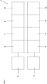
- FIG. 1 a schematic representation of a dosing device 1 of the prior art is shown.
- the dosing device 1 comprises at least one corresponding actuator 2, with the aid of which the displacement element can be driven.
- one or more sensors 3 can be provided.
- a sensor for measuring a pH value can be present.
- Hardware and software must be provided within the dosing device that provides the actuator control 4, the sensor data acquisition 5, the actual control task 6, the provision of computing power 7, the control of other inputs and outputs 8, the sequence control 9, possibly other functions such as data logging and data visualization 10, as well as appropriate user guidance 11.
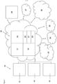
- the dosing device 12 consists of a sensor 13 and an actuator 14 and, if necessary, an emergency control 15.
- Both the sensor 13 and the actuator 14 can be networked, i.e. can communicate via a communication interface with a server 16 that is located remotely.
- the server which can be virtualized, for example, is responsible for the provision of computing power 17, the sequence control 18, the control task 19, provides a web server 20, allows software updates 21 and can, if necessary, enable additional functionalities 22 acquired by the customer.
- the remotely located server 16 can accommodate additional Internet services 23, can have a connection to a web PLC system 24, a data logger 25.
- a maintenance server 26 can also be provided.
- an alarm 27 can be triggered and data can be visualized via a remote access interface 28, for example via a PC, smartphone or tablet computer.
Landscapes
- Engineering & Computer Science (AREA)
- Mechanical Engineering (AREA)
- General Engineering & Computer Science (AREA)
- Physics & Mathematics (AREA)
- General Physics & Mathematics (AREA)
- Fluid Mechanics (AREA)
- Computer Hardware Design (AREA)
- Computer Networks & Wireless Communication (AREA)
- Automation & Control Theory (AREA)
- Infusion, Injection, And Reservoir Apparatuses (AREA)
- Arrangements For Transmission Of Measured Signals (AREA)
- Feeding, Discharge, Calcimining, Fusing, And Gas-Generation Devices (AREA)
Claims (10)
- Appareil de dosage (1, 12) pourvu d'une chambre de dosage, dans laquelle un élément de déplacement est monté mobile de façon à pouvoir être déplacé en va-et-vient entre deux positions, le volume de la chambre de dosage étant plus grand dans une position que dans l'autre, l'appareil de dosage (1, 12) comprenant en outre :- un actionneur (2, 14) destiné à entraîner l'élément de déplacement, qui comporte une entrée d'actionneur pour un signal électrique de commande et est conçu de telle sorte qu'un signal électrique de commande appliqué à l'entrée d'actionneur soit converti en un mouvement mécanique,- un capteur (3, 13) destiné à détecter une grandeur de mesure physique ou chimique, qui comporte une sortie de capteur pour un signal électrique de mesure et est conçu de façon à détecter la grandeur de mesure physique ou chimique, à la convertir en un signal électrique de mesure et à mettre celui-ci à disposition à la sortie de capteur,- une interface de communication via laquelle l'appareil de dosage (1, 12) peut communiquer avec un serveur (16) placé à distance,caractérisé en ce que
l'actionneur (2, 14), le capteur (3, 13) et l'interface de communication sont conçus de telle sorte qu'un signal électrique de mesure disponible à la sortie de capteur lors du fonctionnement de l'appareil de dosage (1, 12) puisse être transmis au serveur distant (16) via l'interface de communication, et un signal électrique de commande puisse être reçu via l'interface de communication et transmis à l'entrée d'actionneur, un dispositif d'urgence étant prévu qui détecte si l'appareil de dosage (1, 12) communique avec un serveur distant (16) via l'interface de communication, et, si aucune communication n'est détectée ou si aucune communication n'est détectée au-delà d'un intervalle de temps prédéterminé, déclenche un arrêt d'urgence ou une régulation en fonctionnement de secours. - Appareil de dosage (1, 12) selon la revendication 1, caractérisé en ce que le capteur (3, 13) comporte une entrée de fonctionnement de capteur pour un signal électrique de fonctionnement, un dispositif de génération de signal de fonctionnement étant prévu, lequel peut générer un signal électrique de fonctionnement et est relié à l'entrée de fonctionnement de capteur, le dispositif de génération de signal de fonctionnement étant conçu de façon à pouvoir communiquer, via l'interface de communication, avec un serveur (16) placé à distance.
- Appareil de dosage (1, 12) selon l'une des revendications 1 à 2, caractérisé en ce qu'est prévu un autre capteur (3, 13) destiné à détecter une autre grandeur de mesure physique ou chimique, qui comporte une sortie de capteur pour un signal électrique de mesure et est conçu pour détecter l'autre grandeur de mesure physique ou chimique, la convertir en un signal électrique de mesure et mettre celui-ci à disposition à la sortie de capteur, l'autre capteur (3, 13) et l'interface de communication étant conçus de telle sorte qu'un signal électrique de mesure disponible à la sortie de capteur de l'autre capteur (3, 13) puisse être transmis, via l'interface de communication, au serveur (16) placé à distance.
- Système de dosage comprenant au moins un appareil de dosage (1, 12) avec une chambre de dosage, dans laquelle un élément de déplacement est monté mobile de façon à pouvoir être déplacé en va-et-vient entre deux positions, le volume de la chambre de dosage étant plus grand dans une position que dans l'autre, l'appareil de dosage (1, 12) comprenant en outre :- un actionneur (2, 14) destiné à entraîner l'élément de déplacement, qui comporte une entrée d'actionneur pour un signal électrique de commande et est conçu de telle sorte qu'un signal électrique de commande appliqué à l'entrée d'actionneur soit converti en un mouvement mécanique,- un capteur (3, 13) destiné à détecter une grandeur de mesure physique ou chimique, qui comporte une sortie de capteur pour un signal électrique de mesure et est conçu de façon à détecter la grandeur de mesure physique ou chimique, à la convertir en un signal électrique de mesure et à mettre celui-ci à disposition à la sortie de capteur,- une interface de communication via laquelle l'appareil de dosage (1, 12) peut communiquer avec un serveur (16) placé à distance,caractérisé en ce que
l'actionneur (2, 14), le capteur (3, 13) et l'interface de communication sont conçus de telle sorte qu'un signal électrique de mesure disponible à la sortie de capteur lors du fonctionnement de l'appareil de dosage (1, 12) puisse être transmis au serveur distant (16) via l'interface de communication, et un signal électrique de commande puisse être reçu via l'interface de communication et transmis à l'entrée d'actionneur, le système de dosage comprenant un serveur (16) placé à distance, doté d'un logiciel d'appareil de dosage qui réalise un moyen de régulation dans lequel le signal électrique de mesure transmis via l'interface de communication est comparé à une courbe de valeurs de consigne, à partir de laquelle est calculée une grandeur de réglage, et la grandeur de réglage est transmise sous forme de signal électrique de commande à l'entrée d'actionneur via l'interface de communication. - Système de dosage selon la revendication 4, caractérisé en ce que le serveur (16) comprend une interface d'accès à distance, permettant la communication avec le logiciel d'appareil de dosage depuis un appareil externe, l'interface d'accès à distance étant de préférence une interface web.
- Système de dosage selon l'une des revendications 4 à 5, caractérisé en ce que le logiciel d'appareil de dosage est pourvu d'un dispositif d'alarme qui est en mesure d'envoyer un message d'alarme à un appareil externe.
- Système de dosage selon l'une des revendications 4 à 6, caractérisé en ce qu'est prévue une pluralité d'appareils de dosage (1, 12) selon l'une des revendications 1 à 3.
- Système de dosage selon l'une des revendications 4 à 7, caractérisé en ce que le serveur (16) comporte un enregistreur de données pouvant communiquer avec le logiciel d'appareil de dosage.
- Système de dosage selon l'une des revendications 4 à 8, caractérisé en ce que le serveur (16) comporte une interface de maintenance permettant d'accéder au serveur (16) depuis un serveur de maintenance (26).
- Système d'installation de dosage pourvue d'une pluralité de systèmes de dosage selon l'une des revendications 4 à 9 et d'un serveur de maintenance (26) par l'intermédiaire duquel le logiciel d'appareil de dosage peut être remplacé et le contenu de l'enregistreur de données peut être lu.
Applications Claiming Priority (2)
| Application Number | Priority Date | Filing Date | Title |
|---|---|---|---|
| DE102016113214.4A DE102016113214A1 (de) | 2016-07-18 | 2016-07-18 | Dosiereinrichtung mit Kommunikationsschnittstelle |
| PCT/EP2017/067812 WO2018015285A1 (fr) | 2016-07-18 | 2017-07-14 | Dispositif de dosage comprenant une interface de communication |
Publications (3)
| Publication Number | Publication Date |
|---|---|
| EP3485166A1 EP3485166A1 (fr) | 2019-05-22 |
| EP3485166B1 EP3485166B1 (fr) | 2020-04-15 |
| EP3485166B2 true EP3485166B2 (fr) | 2025-02-19 |
Family
ID=59399403
Family Applications (1)
| Application Number | Title | Priority Date | Filing Date |
|---|---|---|---|
| EP17743290.3A Active EP3485166B2 (fr) | 2016-07-18 | 2017-07-14 | Appareil de dosage avec une interface de communication |
Country Status (6)
| Country | Link |
|---|---|
| US (1) | US20190136852A1 (fr) |
| EP (1) | EP3485166B2 (fr) |
| CN (1) | CN109477468B (fr) |
| DE (1) | DE102016113214A1 (fr) |
| TW (1) | TW201816265A (fr) |
| WO (1) | WO2018015285A1 (fr) |
Family Cites Families (29)
| Publication number | Priority date | Publication date | Assignee | Title |
|---|---|---|---|---|
| CA1254091A (fr) * | 1984-09-28 | 1989-05-16 | Vladimir Feingold | Systeme implantable pour la perfusion de medicaments |
| GB2312419B (en) * | 1996-03-22 | 1998-02-11 | Chem Controls Ltd | Dosing control apparatus |
| DE10018866A1 (de) | 2000-04-14 | 2001-10-25 | Grundfos As | Pumpenaggregat |
| US7050808B2 (en) * | 2000-06-07 | 2006-05-23 | Telemics, Inc. | Method and system for transmitting, receiving and collecting information related to a plurality of working components |
| US20020155832A1 (en) * | 2001-04-18 | 2002-10-24 | Stucky Michael J. | Wireless telemetry system |
| US7029456B2 (en) | 2003-10-15 | 2006-04-18 | Baxter International Inc. | Medical fluid therapy flow balancing and synchronization system |
| EP1774487B1 (fr) * | 2004-07-09 | 2016-03-16 | Green, Ezra | Systeme et procede de comptage d'energie a distance |
| DE102005039237A1 (de) | 2005-08-19 | 2007-02-22 | Prominent Dosiertechnik Gmbh | Motordosierpumpe |
| DE102005039772A1 (de) | 2005-08-22 | 2007-03-08 | Prominent Dosiertechnik Gmbh | Magnetdosierpumpe |
| US8087429B2 (en) * | 2005-11-21 | 2012-01-03 | Entegris, Inc. | System and method for a pump with reduced form factor |
| US7283894B2 (en) * | 2006-02-10 | 2007-10-16 | Dresser, Inc. | System and method for fluid regulation |
| US8202267B2 (en) | 2006-10-10 | 2012-06-19 | Medsolve Technologies, Inc. | Method and apparatus for infusing liquid to a body |
| CN101611409B (zh) * | 2006-11-21 | 2013-03-20 | 巴克斯特国际公司 | 用于远程监视和/或管理输注治疗的系统和方法 |
| US20080267076A1 (en) * | 2007-04-30 | 2008-10-30 | At&T Knowledge Ventures, L.P. | System and apparatus for maintaining a communication system |
| AU2009238456B2 (en) * | 2008-04-23 | 2013-09-19 | Principle Power, Inc. | Column-stabilized offshore platform with water-entrapment plates and asymmetric mooring system for support of offshore wind turbines |
| US20120282111A1 (en) * | 2011-05-05 | 2012-11-08 | Nip Kenneth Kei-Ho | System and method of differential pressure control of a reciprocating electrokinetic pump |
| US20130201316A1 (en) * | 2012-01-09 | 2013-08-08 | May Patents Ltd. | System and method for server based control |
| US8620841B1 (en) * | 2012-08-31 | 2013-12-31 | Nest Labs, Inc. | Dynamic distributed-sensor thermostat network for forecasting external events |
| US8649909B1 (en) * | 2012-12-07 | 2014-02-11 | Amplisine Labs, LLC | Remote control of fluid-handling devices |
| US9441625B2 (en) | 2013-01-11 | 2016-09-13 | Mary Ann Schoendorff | System and method for pump component controlling and testing |
| AR095272A1 (es) * | 2013-03-14 | 2015-09-30 | Fisher Controls Int Llc | Pronóstico de válvula en función de análisis de laboratorio |
| GB2513958B (en) * | 2013-03-15 | 2020-07-08 | Fisher Rosemount Systems Inc | Supervisor engine for process control |
| US20160132046A1 (en) * | 2013-03-15 | 2016-05-12 | Fisher-Rosemount Systems, Inc. | Method and apparatus for controlling a process plant with wearable mobile control devices |
| WO2015006777A2 (fr) * | 2013-07-12 | 2015-01-15 | Karamanos John C | Dispositif de mesure de régulation de fluide |
| DE102014010126B4 (de) * | 2014-07-09 | 2016-04-07 | Beatrice Saier | Dosierpumpe, Sendeeinheit, Empfangseinheit und Verfahren |
| CN204265601U (zh) | 2014-10-28 | 2015-04-15 | 王金 | 一种基于物联网的污水处理装置 |
| CN204434366U (zh) | 2015-02-06 | 2015-07-01 | 倪勇强 | 一种智能化自动加药排污装置 |
| DE102016114680A1 (de) * | 2016-08-08 | 2018-02-08 | Prominent Gmbh | Vorrichtung zum Erzeugen eines pulsierenden Hydraulikfluiddruckes |
| DE102016117357A1 (de) * | 2016-09-15 | 2018-03-15 | Prominent Gmbh | Verfahren zum Betreiben von Dosiereinrichtungen |
-
2016
- 2016-07-18 DE DE102016113214.4A patent/DE102016113214A1/de active Pending
-
2017
- 2017-07-14 US US16/097,870 patent/US20190136852A1/en not_active Abandoned
- 2017-07-14 WO PCT/EP2017/067812 patent/WO2018015285A1/fr not_active Ceased
- 2017-07-14 CN CN201780043951.9A patent/CN109477468B/zh active Active
- 2017-07-14 EP EP17743290.3A patent/EP3485166B2/fr active Active
- 2017-07-18 TW TW106123984A patent/TW201816265A/zh unknown
Also Published As
| Publication number | Publication date |
|---|---|
| US20190136852A1 (en) | 2019-05-09 |
| CN109477468B (zh) | 2021-06-08 |
| EP3485166A1 (fr) | 2019-05-22 |
| CN109477468A (zh) | 2019-03-15 |
| EP3485166B1 (fr) | 2020-04-15 |
| DE102016113214A1 (de) | 2018-01-18 |
| TW201816265A (zh) | 2018-05-01 |
| WO2018015285A1 (fr) | 2018-01-25 |
Similar Documents
| Publication | Publication Date | Title |
|---|---|---|
| EP2024712B1 (fr) | Dispositif pour la transmission de valeurs de mesure | |
| EP3263148B1 (fr) | Procédé de détermination de paramètres de fonctionnement d'une pompe à sang | |
| DE3686558T2 (de) | Intravenoese infusionsvorrichtung mit zwei anwendungsmoeglichkeiten. | |
| DE2260490C2 (de) | Verfahren und Vorrichtung zum Überwachen und Steuern einer Bohrloch-Pumpeinrichtung | |
| EP3039289B1 (fr) | Procédé pour déterminer des paramètres hydrauliques dans une pompe à déplacement positif | |
| EP3242035B1 (fr) | Procédé de fonctionnement d'au moins un groupe motopompe parmi une pluralité de groupes motopompe | |
| DE10157143B4 (de) | Wartungsintervallanzeige für Pumpen | |
| EP0279931A2 (fr) | Pompe à membrane | |
| WO2005078287A1 (fr) | Procede de determination d'anomalies lors du fonctionnement d'un groupe de pompage | |
| EP3004648B1 (fr) | Assemblage et procédé pour détecter le volume de refoulement et le débit d'une pompe à mouvement alternatif | |
| EP2913526A1 (fr) | Procédé de transport de fluide hydraulique et unité de pompe/moteur électrohydraulique associée | |
| EP0337092A3 (fr) | Appareil de mesure de la vitesse d'écoulement de fluides | |
| DE102017122373A1 (de) | Betriebszustandsüberwachungsvorrichtung für einen Zylinder | |
| DE102014003247A1 (de) | Verfahren zur Bereitstellung von wenigstens einer Information an einem Pumpenaggregat | |
| WO2018050525A1 (fr) | Procédé pour faire fonctionner des appareils de dosage | |
| EP3485166B2 (fr) | Appareil de dosage avec une interface de communication | |
| EP3861534B1 (fr) | Cylindre avec dispositif de traitement de données | |
| EP4283121B1 (fr) | Pompe de dosage pour installation de lavage des véhicules | |
| EP3592980B1 (fr) | Procédé pour faire fonctionner une pompe de circulation et pompe de circulation pour mettre en oeuvre ce procédé | |
| DE102013006220B4 (de) | Pneumatischer Antrieb und Verfahren zur Erfassung der Leistung eines pneumatischen Antriebs | |
| DE69214832T2 (de) | Gerät zur kontrolle der druckdifferenz | |
| EP3707480B1 (fr) | Procédé permettant la détermination, déclenchée selon l'emplacement, d'au moins une grandeur de processus physique ou chimique | |
| EP3039288A1 (fr) | Procédé d'amélioration de profilés de dosage de pompes volumétriques | |
| DE112021002442T5 (de) | Ventilaktuator, System und Verfahren für Dampfeinspritzventile | |
| EP3452576B1 (fr) | Procédé et dispositif pour le dosage et la conservation de liquides à l'aide de récipients ouverts en permanence |
Legal Events
| Date | Code | Title | Description |
|---|---|---|---|
| STAA | Information on the status of an ep patent application or granted ep patent |
Free format text: STATUS: UNKNOWN |
|
| STAA | Information on the status of an ep patent application or granted ep patent |
Free format text: STATUS: THE INTERNATIONAL PUBLICATION HAS BEEN MADE |
|
| PUAI | Public reference made under article 153(3) epc to a published international application that has entered the european phase |
Free format text: ORIGINAL CODE: 0009012 |
|
| STAA | Information on the status of an ep patent application or granted ep patent |
Free format text: STATUS: REQUEST FOR EXAMINATION WAS MADE |
|
| 17P | Request for examination filed |
Effective date: 20190117 |
|
| AK | Designated contracting states |
Kind code of ref document: A1 Designated state(s): AL AT BE BG CH CY CZ DE DK EE ES FI FR GB GR HR HU IE IS IT LI LT LU LV MC MK MT NL NO PL PT RO RS SE SI SK SM TR |
|
| AX | Request for extension of the european patent |
Extension state: BA ME |
|
| DAV | Request for validation of the european patent (deleted) | ||
| DAX | Request for extension of the european patent (deleted) | ||
| GRAP | Despatch of communication of intention to grant a patent |
Free format text: ORIGINAL CODE: EPIDOSNIGR1 |
|
| STAA | Information on the status of an ep patent application or granted ep patent |
Free format text: STATUS: GRANT OF PATENT IS INTENDED |
|
| RIC1 | Information provided on ipc code assigned before grant |
Ipc: F04B 49/06 20060101ALI20191018BHEP Ipc: F04B 13/00 20060101AFI20191018BHEP Ipc: F04B 43/04 20060101ALI20191018BHEP Ipc: F04B 43/067 20060101ALI20191018BHEP |
|
| INTG | Intention to grant announced |
Effective date: 20191114 |
|
| GRAS | Grant fee paid |
Free format text: ORIGINAL CODE: EPIDOSNIGR3 |
|
| GRAA | (expected) grant |
Free format text: ORIGINAL CODE: 0009210 |
|
| STAA | Information on the status of an ep patent application or granted ep patent |
Free format text: STATUS: THE PATENT HAS BEEN GRANTED |
|
| AK | Designated contracting states |
Kind code of ref document: B1 Designated state(s): AL AT BE BG CH CY CZ DE DK EE ES FI FR GB GR HR HU IE IS IT LI LT LU LV MC MK MT NL NO PL PT RO RS SE SI SK SM TR |
|
| REG | Reference to a national code |
Ref country code: CH Ref legal event code: EP |
|
| REG | Reference to a national code |
Ref country code: DE Ref legal event code: R096 Ref document number: 502017004782 Country of ref document: DE |
|
| REG | Reference to a national code |
Ref country code: IE Ref legal event code: FG4D Free format text: LANGUAGE OF EP DOCUMENT: GERMAN |
|
| REG | Reference to a national code |
Ref country code: AT Ref legal event code: REF Ref document number: 1257604 Country of ref document: AT Kind code of ref document: T Effective date: 20200515 |
|
| REG | Reference to a national code |
Ref country code: NL Ref legal event code: MP Effective date: 20200415 |
|
| REG | Reference to a national code |
Ref country code: LT Ref legal event code: MG4D |
|
| PG25 | Lapsed in a contracting state [announced via postgrant information from national office to epo] |
Ref country code: FI Free format text: LAPSE BECAUSE OF FAILURE TO SUBMIT A TRANSLATION OF THE DESCRIPTION OR TO PAY THE FEE WITHIN THE PRESCRIBED TIME-LIMIT Effective date: 20200415 Ref country code: GR Free format text: LAPSE BECAUSE OF FAILURE TO SUBMIT A TRANSLATION OF THE DESCRIPTION OR TO PAY THE FEE WITHIN THE PRESCRIBED TIME-LIMIT Effective date: 20200716 Ref country code: NO Free format text: LAPSE BECAUSE OF FAILURE TO SUBMIT A TRANSLATION OF THE DESCRIPTION OR TO PAY THE FEE WITHIN THE PRESCRIBED TIME-LIMIT Effective date: 20200715 Ref country code: IS Free format text: LAPSE BECAUSE OF FAILURE TO SUBMIT A TRANSLATION OF THE DESCRIPTION OR TO PAY THE FEE WITHIN THE PRESCRIBED TIME-LIMIT Effective date: 20200815 Ref country code: PT Free format text: LAPSE BECAUSE OF FAILURE TO SUBMIT A TRANSLATION OF THE DESCRIPTION OR TO PAY THE FEE WITHIN THE PRESCRIBED TIME-LIMIT Effective date: 20200817 Ref country code: LT Free format text: LAPSE BECAUSE OF FAILURE TO SUBMIT A TRANSLATION OF THE DESCRIPTION OR TO PAY THE FEE WITHIN THE PRESCRIBED TIME-LIMIT Effective date: 20200415 Ref country code: SE Free format text: LAPSE BECAUSE OF FAILURE TO SUBMIT A TRANSLATION OF THE DESCRIPTION OR TO PAY THE FEE WITHIN THE PRESCRIBED TIME-LIMIT Effective date: 20200415 Ref country code: NL Free format text: LAPSE BECAUSE OF FAILURE TO SUBMIT A TRANSLATION OF THE DESCRIPTION OR TO PAY THE FEE WITHIN THE PRESCRIBED TIME-LIMIT Effective date: 20200415 |
|
| PG25 | Lapsed in a contracting state [announced via postgrant information from national office to epo] |
Ref country code: LV Free format text: LAPSE BECAUSE OF FAILURE TO SUBMIT A TRANSLATION OF THE DESCRIPTION OR TO PAY THE FEE WITHIN THE PRESCRIBED TIME-LIMIT Effective date: 20200415 Ref country code: HR Free format text: LAPSE BECAUSE OF FAILURE TO SUBMIT A TRANSLATION OF THE DESCRIPTION OR TO PAY THE FEE WITHIN THE PRESCRIBED TIME-LIMIT Effective date: 20200415 Ref country code: RS Free format text: LAPSE BECAUSE OF FAILURE TO SUBMIT A TRANSLATION OF THE DESCRIPTION OR TO PAY THE FEE WITHIN THE PRESCRIBED TIME-LIMIT Effective date: 20200415 Ref country code: BG Free format text: LAPSE BECAUSE OF FAILURE TO SUBMIT A TRANSLATION OF THE DESCRIPTION OR TO PAY THE FEE WITHIN THE PRESCRIBED TIME-LIMIT Effective date: 20200715 |
|
| PG25 | Lapsed in a contracting state [announced via postgrant information from national office to epo] |
Ref country code: AL Free format text: LAPSE BECAUSE OF FAILURE TO SUBMIT A TRANSLATION OF THE DESCRIPTION OR TO PAY THE FEE WITHIN THE PRESCRIBED TIME-LIMIT Effective date: 20200415 |
|
| REG | Reference to a national code |
Ref country code: DE Ref legal event code: R026 Ref document number: 502017004782 Country of ref document: DE |
|
| PLBI | Opposition filed |
Free format text: ORIGINAL CODE: 0009260 |
|
| PG25 | Lapsed in a contracting state [announced via postgrant information from national office to epo] |
Ref country code: DK Free format text: LAPSE BECAUSE OF FAILURE TO SUBMIT A TRANSLATION OF THE DESCRIPTION OR TO PAY THE FEE WITHIN THE PRESCRIBED TIME-LIMIT Effective date: 20200415 Ref country code: ES Free format text: LAPSE BECAUSE OF FAILURE TO SUBMIT A TRANSLATION OF THE DESCRIPTION OR TO PAY THE FEE WITHIN THE PRESCRIBED TIME-LIMIT Effective date: 20200415 Ref country code: RO Free format text: LAPSE BECAUSE OF FAILURE TO SUBMIT A TRANSLATION OF THE DESCRIPTION OR TO PAY THE FEE WITHIN THE PRESCRIBED TIME-LIMIT Effective date: 20200415 Ref country code: CZ Free format text: LAPSE BECAUSE OF FAILURE TO SUBMIT A TRANSLATION OF THE DESCRIPTION OR TO PAY THE FEE WITHIN THE PRESCRIBED TIME-LIMIT Effective date: 20200415 Ref country code: EE Free format text: LAPSE BECAUSE OF FAILURE TO SUBMIT A TRANSLATION OF THE DESCRIPTION OR TO PAY THE FEE WITHIN THE PRESCRIBED TIME-LIMIT Effective date: 20200415 Ref country code: IT Free format text: LAPSE BECAUSE OF FAILURE TO SUBMIT A TRANSLATION OF THE DESCRIPTION OR TO PAY THE FEE WITHIN THE PRESCRIBED TIME-LIMIT Effective date: 20200415 Ref country code: SM Free format text: LAPSE BECAUSE OF FAILURE TO SUBMIT A TRANSLATION OF THE DESCRIPTION OR TO PAY THE FEE WITHIN THE PRESCRIBED TIME-LIMIT Effective date: 20200415 |
|
| PLAX | Notice of opposition and request to file observation + time limit sent |
Free format text: ORIGINAL CODE: EPIDOSNOBS2 |
|
| 26 | Opposition filed |
Opponent name: GRUNDFOS HOLDING A/S Effective date: 20210113 |
|
| PG25 | Lapsed in a contracting state [announced via postgrant information from national office to epo] |
Ref country code: MC Free format text: LAPSE BECAUSE OF FAILURE TO SUBMIT A TRANSLATION OF THE DESCRIPTION OR TO PAY THE FEE WITHIN THE PRESCRIBED TIME-LIMIT Effective date: 20200415 Ref country code: PL Free format text: LAPSE BECAUSE OF FAILURE TO SUBMIT A TRANSLATION OF THE DESCRIPTION OR TO PAY THE FEE WITHIN THE PRESCRIBED TIME-LIMIT Effective date: 20200415 Ref country code: SK Free format text: LAPSE BECAUSE OF FAILURE TO SUBMIT A TRANSLATION OF THE DESCRIPTION OR TO PAY THE FEE WITHIN THE PRESCRIBED TIME-LIMIT Effective date: 20200415 |
|
| REG | Reference to a national code |
Ref country code: CH Ref legal event code: PL |
|
| REG | Reference to a national code |
Ref country code: BE Ref legal event code: MM Effective date: 20200731 |
|
| PG25 | Lapsed in a contracting state [announced via postgrant information from national office to epo] |
Ref country code: LI Free format text: LAPSE BECAUSE OF NON-PAYMENT OF DUE FEES Effective date: 20200731 Ref country code: LU Free format text: LAPSE BECAUSE OF NON-PAYMENT OF DUE FEES Effective date: 20200714 Ref country code: CH Free format text: LAPSE BECAUSE OF NON-PAYMENT OF DUE FEES Effective date: 20200731 |
|
| PG25 | Lapsed in a contracting state [announced via postgrant information from national office to epo] |
Ref country code: SI Free format text: LAPSE BECAUSE OF FAILURE TO SUBMIT A TRANSLATION OF THE DESCRIPTION OR TO PAY THE FEE WITHIN THE PRESCRIBED TIME-LIMIT Effective date: 20200415 Ref country code: BE Free format text: LAPSE BECAUSE OF NON-PAYMENT OF DUE FEES Effective date: 20200731 |
|
| PLBB | Reply of patent proprietor to notice(s) of opposition received |
Free format text: ORIGINAL CODE: EPIDOSNOBS3 |
|
| PG25 | Lapsed in a contracting state [announced via postgrant information from national office to epo] |
Ref country code: IE Free format text: LAPSE BECAUSE OF NON-PAYMENT OF DUE FEES Effective date: 20200714 |
|
| PGFP | Annual fee paid to national office [announced via postgrant information from national office to epo] |
Ref country code: FR Payment date: 20210729 Year of fee payment: 5 |
|
| PGFP | Annual fee paid to national office [announced via postgrant information from national office to epo] |
Ref country code: GB Payment date: 20210722 Year of fee payment: 5 |
|
| PG25 | Lapsed in a contracting state [announced via postgrant information from national office to epo] |
Ref country code: TR Free format text: LAPSE BECAUSE OF FAILURE TO SUBMIT A TRANSLATION OF THE DESCRIPTION OR TO PAY THE FEE WITHIN THE PRESCRIBED TIME-LIMIT Effective date: 20200415 Ref country code: MT Free format text: LAPSE BECAUSE OF FAILURE TO SUBMIT A TRANSLATION OF THE DESCRIPTION OR TO PAY THE FEE WITHIN THE PRESCRIBED TIME-LIMIT Effective date: 20200415 Ref country code: CY Free format text: LAPSE BECAUSE OF FAILURE TO SUBMIT A TRANSLATION OF THE DESCRIPTION OR TO PAY THE FEE WITHIN THE PRESCRIBED TIME-LIMIT Effective date: 20200415 |
|
| PG25 | Lapsed in a contracting state [announced via postgrant information from national office to epo] |
Ref country code: MK Free format text: LAPSE BECAUSE OF FAILURE TO SUBMIT A TRANSLATION OF THE DESCRIPTION OR TO PAY THE FEE WITHIN THE PRESCRIBED TIME-LIMIT Effective date: 20200415 |
|
| RDAF | Communication despatched that patent is revoked |
Free format text: ORIGINAL CODE: EPIDOSNREV1 |
|
| APAH | Appeal reference modified |
Free format text: ORIGINAL CODE: EPIDOSCREFNO |
|
| APBM | Appeal reference recorded |
Free format text: ORIGINAL CODE: EPIDOSNREFNO |
|
| APBP | Date of receipt of notice of appeal recorded |
Free format text: ORIGINAL CODE: EPIDOSNNOA2O |
|
| APBQ | Date of receipt of statement of grounds of appeal recorded |
Free format text: ORIGINAL CODE: EPIDOSNNOA3O |
|
| GBPC | Gb: european patent ceased through non-payment of renewal fee |
Effective date: 20220714 |
|
| PG25 | Lapsed in a contracting state [announced via postgrant information from national office to epo] |
Ref country code: FR Free format text: LAPSE BECAUSE OF NON-PAYMENT OF DUE FEES Effective date: 20220731 |
|
| PG25 | Lapsed in a contracting state [announced via postgrant information from national office to epo] |
Ref country code: GB Free format text: LAPSE BECAUSE OF NON-PAYMENT OF DUE FEES Effective date: 20220714 |
|
| REG | Reference to a national code |
Ref country code: AT Ref legal event code: MM01 Ref document number: 1257604 Country of ref document: AT Kind code of ref document: T Effective date: 20220714 |
|
| PG25 | Lapsed in a contracting state [announced via postgrant information from national office to epo] |
Ref country code: AT Free format text: LAPSE BECAUSE OF NON-PAYMENT OF DUE FEES Effective date: 20220714 |
|
| APBU | Appeal procedure closed |
Free format text: ORIGINAL CODE: EPIDOSNNOA9O |
|
| PUAH | Patent maintained in amended form |
Free format text: ORIGINAL CODE: 0009272 |
|
| STAA | Information on the status of an ep patent application or granted ep patent |
Free format text: STATUS: PATENT MAINTAINED AS AMENDED |
|
| 27A | Patent maintained in amended form |
Effective date: 20250219 |
|
| AK | Designated contracting states |
Kind code of ref document: B2 Designated state(s): AL AT BE BG CH CY CZ DE DK EE ES FI FR GB GR HR HU IE IS IT LI LT LU LV MC MK MT NL NO PL PT RO RS SE SI SK SM TR |
|
| REG | Reference to a national code |
Ref country code: DE Ref legal event code: R102 Ref document number: 502017004782 Country of ref document: DE |
|
| PGFP | Annual fee paid to national office [announced via postgrant information from national office to epo] |
Ref country code: DE Payment date: 20250717 Year of fee payment: 9 |