EP3485166B2 - Dosiereinrichtung mit kommunikationsschnittstelle - Google Patents
Dosiereinrichtung mit kommunikationsschnittstelle Download PDFInfo
- Publication number
- EP3485166B2 EP3485166B2 EP17743290.3A EP17743290A EP3485166B2 EP 3485166 B2 EP3485166 B2 EP 3485166B2 EP 17743290 A EP17743290 A EP 17743290A EP 3485166 B2 EP3485166 B2 EP 3485166B2
- Authority
- EP
- European Patent Office
- Prior art keywords
- metering
- server
- sensor
- communication interface
- way
- Prior art date
- Legal status (The legal status is an assumption and is not a legal conclusion. Google has not performed a legal analysis and makes no representation as to the accuracy of the status listed.)
- Active
Links
Images
Classifications
-
- F—MECHANICAL ENGINEERING; LIGHTING; HEATING; WEAPONS; BLASTING
- F04—POSITIVE - DISPLACEMENT MACHINES FOR LIQUIDS; PUMPS FOR LIQUIDS OR ELASTIC FLUIDS
- F04B—POSITIVE-DISPLACEMENT MACHINES FOR LIQUIDS; PUMPS
- F04B49/00—Control, e.g. of pump delivery, or pump pressure of, or safety measures for, machines, pumps, or pumping installations, not otherwise provided for, or of interest apart from, groups F04B1/00 - F04B47/00
- F04B49/06—Control using electricity
- F04B49/065—Control using electricity and making use of computers
-
- F—MECHANICAL ENGINEERING; LIGHTING; HEATING; WEAPONS; BLASTING
- F04—POSITIVE - DISPLACEMENT MACHINES FOR LIQUIDS; PUMPS FOR LIQUIDS OR ELASTIC FLUIDS
- F04B—POSITIVE-DISPLACEMENT MACHINES FOR LIQUIDS; PUMPS
- F04B13/00—Pumps specially modified to deliver fixed or variable measured quantities
-
- F—MECHANICAL ENGINEERING; LIGHTING; HEATING; WEAPONS; BLASTING
- F04—POSITIVE - DISPLACEMENT MACHINES FOR LIQUIDS; PUMPS FOR LIQUIDS OR ELASTIC FLUIDS
- F04B—POSITIVE-DISPLACEMENT MACHINES FOR LIQUIDS; PUMPS
- F04B43/00—Machines, pumps, or pumping installations having flexible working members
- F04B43/02—Machines, pumps, or pumping installations having flexible working members having plate-like flexible members, e.g. diaphragms
- F04B43/04—Pumps having electric drive
-
- F—MECHANICAL ENGINEERING; LIGHTING; HEATING; WEAPONS; BLASTING
- F04—POSITIVE - DISPLACEMENT MACHINES FOR LIQUIDS; PUMPS FOR LIQUIDS OR ELASTIC FLUIDS
- F04B—POSITIVE-DISPLACEMENT MACHINES FOR LIQUIDS; PUMPS
- F04B43/00—Machines, pumps, or pumping installations having flexible working members
- F04B43/02—Machines, pumps, or pumping installations having flexible working members having plate-like flexible members, e.g. diaphragms
- F04B43/06—Pumps having fluid drive
- F04B43/067—Pumps having fluid drive the fluid being actuated directly by a piston
-
- G—PHYSICS
- G01—MEASURING; TESTING
- G01F—MEASURING VOLUME, VOLUME FLOW, MASS FLOW OR LIQUID LEVEL; METERING BY VOLUME
- G01F11/00—Apparatus requiring external operation adapted at each repeated and identical operation to measure and separate a predetermined volume of fluid or fluent solid material from a supply or container, without regard to weight, and to deliver it
- G01F11/02—Apparatus requiring external operation adapted at each repeated and identical operation to measure and separate a predetermined volume of fluid or fluent solid material from a supply or container, without regard to weight, and to deliver it with measuring chambers which expand or contract during measurement
- G01F11/08—Apparatus requiring external operation adapted at each repeated and identical operation to measure and separate a predetermined volume of fluid or fluent solid material from a supply or container, without regard to weight, and to deliver it with measuring chambers which expand or contract during measurement of the diaphragm or bellows type
- G01F11/086—Apparatus requiring external operation adapted at each repeated and identical operation to measure and separate a predetermined volume of fluid or fluent solid material from a supply or container, without regard to weight, and to deliver it with measuring chambers which expand or contract during measurement of the diaphragm or bellows type using an auxiliary pressure to cooperate with the diaphragm or bellows
-
- G—PHYSICS
- G01—MEASURING; TESTING
- G01F—MEASURING VOLUME, VOLUME FLOW, MASS FLOW OR LIQUID LEVEL; METERING BY VOLUME
- G01F15/00—Details of, or accessories for, apparatus of groups G01F1/00 - G01F13/00 insofar as such details or appliances are not adapted to particular types of such apparatus
- G01F15/06—Indicating or recording devices
-
- G—PHYSICS
- G05—CONTROLLING; REGULATING
- G05D—SYSTEMS FOR CONTROLLING OR REGULATING NON-ELECTRIC VARIABLES
- G05D7/00—Control of flow
- G05D7/06—Control of flow characterised by the use of electric means
- G05D7/0617—Control of flow characterised by the use of electric means specially adapted for fluid materials
- G05D7/0623—Control of flow characterised by the use of electric means specially adapted for fluid materials characterised by the set value given to the control element
-
- H—ELECTRICITY
- H04—ELECTRIC COMMUNICATION TECHNIQUE
- H04Q—SELECTING
- H04Q9/00—Arrangements in telecontrol or telemetry systems for selectively calling a substation from a main station, in which substation desired apparatus is selected for applying a control signal thereto or for obtaining measured values therefrom
-
- F—MECHANICAL ENGINEERING; LIGHTING; HEATING; WEAPONS; BLASTING
- F04—POSITIVE - DISPLACEMENT MACHINES FOR LIQUIDS; PUMPS FOR LIQUIDS OR ELASTIC FLUIDS
- F04B—POSITIVE-DISPLACEMENT MACHINES FOR LIQUIDS; PUMPS
- F04B2201/00—Pump parameters
- F04B2201/02—Piston parameters
- F04B2201/0201—Position of the piston
-
- F—MECHANICAL ENGINEERING; LIGHTING; HEATING; WEAPONS; BLASTING
- F04—POSITIVE - DISPLACEMENT MACHINES FOR LIQUIDS; PUMPS FOR LIQUIDS OR ELASTIC FLUIDS
- F04B—POSITIVE-DISPLACEMENT MACHINES FOR LIQUIDS; PUMPS
- F04B2205/00—Fluid parameters
-
- H—ELECTRICITY
- H04—ELECTRIC COMMUNICATION TECHNIQUE
- H04Q—SELECTING
- H04Q2209/00—Arrangements in telecontrol or telemetry systems
- H04Q2209/60—Arrangements in telecontrol or telemetry systems for transmitting utility meters data, i.e. transmission of data from the reader of the utility meter
Definitions
- the present invention relates to a dosing device with a dosing chamber in which a displacement element is movably arranged such that it can be moved back and forth between two positions, wherein the volume of the dosing chamber is larger in one position than in the other position.
- the dosing device also has an actuator for driving the displacement element, which has an actuator input for an electrical control signal and is designed such that an electrical control signal applied to the actuator input is converted into a mechanical movement. Furthermore, the dosing device has a sensor for detecting a physical or chemical measurement variable, which has a sensor output for an electrical measurement signal and is designed such that it detects the physical or chemical measurement variable, converts it into an electrical measurement signal and makes this available at the sensor output. Finally, the dosing device has a communication interface via which the dosing device can communicate with a remotely located server.
- Such a dosing device can be, for example, a diaphragm dosing pump.
- a movable diaphragm serves as the displacement element.
- the dosing chamber is connected to a suction line via a suction check valve and to a pressure line via a pressure check valve.
- Both the suction check valve and the pressure check valve can be part of the dosing device. However, they can also be provided on the system side.
- the membrane if the membrane is moved to the position in which the volume of the dosing chamber is the largest, the medium to be pumped is sucked from the suction line into the dosing chamber via the suction valve. The membrane is then moved towards the position in which the volume of the dosing chamber is the smallest, causing the suction check valve to close, whereupon the pressure in the dosing chamber increases until the pressure check valve opens and the medium to be pumped in the dosing chamber is pressed into the pressure line.
- a corresponding drive actuator is provided so that the membrane, i.e. the displacement element, can be moved back and forth between the two positions.
- the membrane can be driven hydraulically so that the actuator is a corresponding piston, one surface of which is in contact with the hydraulic fluid.
- the membrane could also be driven magnetically.
- the membrane could be firmly connected to a push rod that is mounted in a magnetic casing that is firmly anchored in the pump housing and can move axially along its longitudinal axis, so that when the magnetic coil is electrically activated, the push rod and thus the membrane is pulled into the hole in the magnetic casing against the action of a compression spring, and the push rod returns to its original position after the magnet is deactivated by the compression spring, so that the membrane performs an oscillating movement as the magnetic coil continues to be activated and deactivated.
- the magnetic coil is to be regarded as an actuator.
- dosing devices often have a sensor for recording a physical or chemical measurement variable.
- the pH value of the medium to be pumped could be recorded in the pressure line.
- the current and/or voltage can also be recorded by the magnetic coil forming the actuator.
- the sensor records the corresponding measurement variable during operation and converts the recorded measurement variable into an electrical measurement signal that it makes available at the sensor output.
- the sensor can therefore measure, for example, an operating variable of the dosing device (e.g. current or voltage of the drive, position of the displacement element, pressure in the dosing chamber) or an external variable (e.g. pH value in the pressure or suction line, ambient temperature, air pressure, etc.).
- an operating variable of the dosing device e.g. current or voltage of the drive, position of the displacement element, pressure in the dosing chamber
- an external variable e.g. pH value in the pressure or suction line, ambient temperature, air pressure, etc.
- the EP 1 757 809 A1 describes a motion-controlled magnetic metering pump. This has a position sensor as a sensor, which detects the position of the membrane or the push rod connected to the membrane. The magnetic metering pump described there compares the detected position with a specified target value profile and controls the movement of the displacement element in such a way that the deviation between the actual position and the target position is as small as possible.
- the known dosing device therefore has a corresponding control device with the help of which a controlled dosing can be carried out.
- the corresponding control process is stored in a software that is stored within the dosing device.
- corresponding inputs must be made on the device itself in order to inform the dosing device in which form the corresponding control should take place.
- the pump manufacturer develops improved control methods, which, however, cannot be used directly by the dosing device. It is therefore necessary for a service technician on site to update the software on the dosing device using a firmware update.
- a service technician on site to update the software on the dosing device using a firmware update.
- dosing devices are provided with ever greater computing and storage power, with the result that older models of dosing devices can no longer be provided with current firmware updates because they no longer meet the corresponding computing and/or storage requirements.
- the improved control methods must either be dispensed with or or the entire dosing device must be replaced.
- the EP 1 754 891 A2 and the US 2012/0282111 A1 show adjustable pumps.
- the US 2002/0155832 shows a wireless telemetry system.
- the GB 2312419 describes a dosing control device.
- the actuator, sensor and communication interface are designed in such a way that an electrical measurement signal present at the sensor output can be transmitted to the remote server via the communication interface and an electrical control signal can be received via the communication interface and transmitted to the actuator input.
- the actual control task is transferred from the dosing device to the remote server.
- the dosing device itself therefore only needs to be able to transmit the electrical measurement signal present at the sensor output to the remote server and receive a corresponding electrical control signal for the actuator input from the remote server.
- the communication interface is preferably a network interface, i.e. an interface that allows the sensor and actuator access to a computer network.
- the remote server must also have a corresponding communication interface designed as a network interface in order to also allow the server access to the computer network.
- a dosing system could comprise at least one of the dosing devices according to the invention and a server arranged remotely from the dosing device with dosing device software, wherein the dosing device software implements a control device in which the electrical measurement signal transmitted via the communication interface is compared with a setpoint curve, a manipulated variable is calculated therefrom and the manipulated variable is transmitted as an electrical control signal via the communication interface to the actuator input.
- the remotely arranged server does not have to be arranged in the same room as the dosing device, but can be arranged, for example, in the neighboring room or in any room that has a corresponding process control center.
- the communication interface is particularly preferably designed such that it can communicate via the Internet, so that the remote server can be arranged at any location, e.g. at the dosing device manufacturer.
- the dosing system can have a plurality of dosing devices, all of which communicate with the remotely arranged server.
- the senor has a sensor operating input for an electrical operating signal, wherein an operating signal generating device is provided which can generate an electrical operating signal and is connected to the sensor operating input, wherein the operating signal generating device is designed such that it can communicate with a remotely arranged server via the communication interface.
- an activation mode can be started, for example.
- the type of activation can depend on various factors, such as the specific application, the type of medium to be pumped, the concentration curve over time or the age of the sensor. Because the operating signal generation device can communicate with a remotely located server, the corresponding operating voltage can be determined by the remotely located server.
- the activation mode to increase the measuring signal can be triggered by communication with the remotely located sensor.
- the senor can be arranged in the dosing chamber.
- the sensor can detect an operating variable of the drive of the displacement element.
- Operating variables of the actuator can be, for example, the position of the displacement element or the voltage or current at the actuator.
- the dosing device has a further sensor for detecting a further physical or chemical measurement variable, which also has a sensor output for an electrical measurement signal and is designed such that it detects the further physical or chemical measurement variable, converts it into an electrical measurement signal and makes this available at the sensor output, wherein the further sensor and the communication interface are designed such that an electrical measurement signal present at the sensor output of the further sensor can be transmitted to the remotely arranged server via the communication interface.
- the dosing device software provided on the remote server thus has information about the value of another physical or chemical measurement variable. This information can be integrated into the control device, for example. It can also be used instead or in addition for an emergency shutdown or an alarm.
- a An emergency device is provided which detects whether the dosing device is communicating with a remote server via the communication interface and, if no communication is detected or no communication is detected for longer than a predetermined time interval, initiates an emergency shutdown.
- the emergency device can interrupt the corresponding dosing function if the connection to the remote server fails for any reason.
- the emergency device could also have a corresponding emergency control.
- This emergency control must take place without a connection to the remote server.
- the emergency control could transmit a pattern of the electrical control signal last received from the remote server to the actuator input.
- the actuator is the solenoid coil of the magnetic drive of a metering pump
- a time-varying control signal (signal pattern) is received by the remote server during normal operation and transmitted to the actuator input.
- the last time-varying control signal received could continue to be used.
- a current adjustment of the signal pattern could then not take place during the emergency control, but the connection interruptions are usually only brief, so that as soon as the connection is re-established, the remote server can take over its task again.
- a reference stroke frequency could also be stored in the metering pump and, in the case of emergency control, the metering pump could be operated at the reference stroke frequency. If desired, if the connection to the remote server is interrupted for more than a predetermined period of time, the emergency control can be aborted and an emergency shutdown can be carried out.
- the server has a remote access interface via which an external device can communicate with the dosing device software, wherein the remote access interface is preferably a web interface.
- the remote access interface is preferably a web interface.
- the customer using the dosing device can access the software via the remote access interface and retrieve the relevant information. For example, information about the measured physical or chemical parameters can be visualized on a PC, a smartphone or a tablet computer.
- the desired dosing speed can be set via the remote access interface.
- the dosing device software has an alarm device that is able to send an alarm message to an external device. If, for example, the dosing device software on the remotely located server determines that the recorded physical or chemical measured variable deviates too much from the expected measured variable value, it can alert the user of the dosing device accordingly, for example by sending an SMS or an email or by posting a corresponding Twitter message.
- the server has a data logger that can communicate with the dosing device software. All available data relating to the dosing device is stored in the data logger. The data logger can thus be used to determine the running time of the dosing device and the operating conditions, such as dosing speed and delivery pressure, that existed in the dosing application used.
- the server has a maintenance interface via which the server can be accessed from a maintenance server.
- the content of the data logger can be retrieved via the maintenance server, for example. It is also possible to replace the dosing device software or to activate certain functionalities of the software.
- a dosing system is equipped with a plurality of dosing devices, all of which are connected to a server located on the dosing system's premises on which the dosing device software is stored.
- a corresponding maintenance server can then be located at the dosing device manufacturer.
- the maintenance server a large number of servers can then be accessed, whereby, for example, the dosing device software can be exchanged and/or the contents of the data logger can be read out, whereby the servers in turn control a plurality of dosing devices.
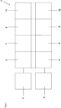
- FIG. 1 a schematic representation of a dosing device 1 of the prior art is shown.
- the dosing device 1 comprises at least one corresponding actuator 2, with the aid of which the displacement element can be driven.
- one or more sensors 3 can be provided.
- a sensor for measuring a pH value can be present.
- Hardware and software must be provided within the dosing device that provides the actuator control 4, the sensor data acquisition 5, the actual control task 6, the provision of computing power 7, the control of other inputs and outputs 8, the sequence control 9, possibly other functions such as data logging and data visualization 10, as well as appropriate user guidance 11.
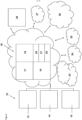
- the dosing device 12 consists of a sensor 13 and an actuator 14 and, if necessary, an emergency control 15.
- Both the sensor 13 and the actuator 14 can be networked, i.e. can communicate via a communication interface with a server 16 that is located remotely.
- the server which can be virtualized, for example, is responsible for the provision of computing power 17, the sequence control 18, the control task 19, provides a web server 20, allows software updates 21 and can, if necessary, enable additional functionalities 22 acquired by the customer.
- the remotely located server 16 can accommodate additional Internet services 23, can have a connection to a web PLC system 24, a data logger 25.
- a maintenance server 26 can also be provided.
- an alarm 27 can be triggered and data can be visualized via a remote access interface 28, for example via a PC, smartphone or tablet computer.
Landscapes
- Engineering & Computer Science (AREA)
- Mechanical Engineering (AREA)
- General Engineering & Computer Science (AREA)
- Physics & Mathematics (AREA)
- General Physics & Mathematics (AREA)
- Fluid Mechanics (AREA)
- Computer Hardware Design (AREA)
- Computer Networks & Wireless Communication (AREA)
- Automation & Control Theory (AREA)
- Arrangements For Transmission Of Measured Signals (AREA)
- Infusion, Injection, And Reservoir Apparatuses (AREA)
- Feeding, Discharge, Calcimining, Fusing, And Gas-Generation Devices (AREA)
Description
- Die vorliegende Erfindung betrifft eine Dosiereinrichtung mit einer Dosierkammer, in der ein Verdrängungselement derart beweglich angeordnet ist, dass es zwischen zwei Positionen hin- und herbewegbar ist, wobei das Volumen der Dosierkammer in der einen Position größer als in der anderen Position ist.
- Die Dosiereinrichtung weist weiterhin einen Aktor zum Antreiben des Verdrängungselementes auf, welcher einen Aktoreingang für ein elektrisches Ansteuersignal aufweist und derart aufgebaut ist, dass ein am Aktoreingang anliegendes elektrisches Ansteuersignal in eine mechanische Bewegung umgesetzt wird. Des Weiteren weist die Dosiereinrichtung einen Sensor zur Erfassung einer physikalischen oder chemischen Messgröße auf, der einen Sensorausgang für ein elektrisches Messsignal aufweist und derart ausgebildet ist, dass er die physikalische oder chemische Messgröße erfasst, in ein elektrisches Messsignal umsetzt und dieses am Sensorausgang zur Verfügung stellt. Schließlich weist die Dosiereinrichtung eine Kommunikationsschnittstelle auf, über die die Dosiereinrichtung mit einem entfernt angeordneten Server kommunizieren kann.
- Eine solche Dosiereinrichtung kann bspw. eine Membrandosierpumpe sein. Als Verdrängungselement dient hier eine bewegliche Membran.
- Die Dosierkammer ist im Betrieb über ein Saugrückschlagventil mit einer Saugleitung und über ein Druckrückschlagventil mit einer Druckleitung verbunden. Sowohl Saugrückschlagventil als auch Druckrückschlagventil können Teil der Dosiereinrichtung sein. Sie können jedoch auch anlagenseitig bereitgestellt werden.
- Wird daher die Membran in die Position bewegt, in der das Volumen der Dosierkammer am größten ist, wird zu förderndes Medium über das Saugventil aus der Saugleitung in die Dosierkammer gesaugt. Im Anschluss daran wird die Membran in Richtung derjenigen Position bewegt, in der das Volumen der Dosierkammer am geringsten ist, wodurch bewirkt wird, dass das Saugrückschlagventil geschlossen wird, worauf der Druck in der Dosierkammer ansteigt bis das Druckrückschlagventil öffnet und das sich in der Dosierkammer befindliche zu fördernde Medium in die Druckleitung gedrückt wird. Damit die Membran, d.h. das Verdrängungselement zwischen den beiden Positionen hin- und herbewegt werden kann, ist ein entsprechender Antriebsaktor vorgesehen. Beispielsweise kann die Membran hydraulisch angetrieben werden, sodass der Aktor ein entsprechender Kolben ist, dessen eine Fläche mit dem Hydraulikfluid in Kontakt steht.
- Alternativ könnte die Membran auch magnetisch angetrieben werden. Beispielsweise könnte die Membran mit einer Schubstange fest verbunden sein, die in einem im Pumpengehäuse fest verankerten Magnetmantel in der Längsachse axial beweglich gelagert ist, sodass die Schubstange und damit die Membran bei der elektrischen Ansteuerung der Magnetspule in den Magnetmantel gegen die Wirkung einer Druckfeder in die Bohrung des Magnetmantels hinein gezogen wird und die Schubstange nach Deaktivierung des Magneten durch die Druckfeder in die Ausgangslage zurückkehrt, sodass die Membran bei fortgesetzter Aktivierung und Deaktivierung der Magnetspule eine oszillierende Bewegung durchführt. In diesem Fall ist die Magnetspule als Aktor anzusehen.
- Diese Dosiereinrichtungen weisen häufig einen Sensor zur Erfassung einer physikalischen oder chemischen Messgröße auf. Beispielsweise könnte der pH-Wert des zu fördernden Mediums in der Druckleitung erfasst werden. Alternativ kann aber auch der Strom und/oder die Spannung durch die den Aktor bildende Magnetspule erfasst werden. Der Sensor erfasst die entsprechende Messgröße im Betrieb und wandelt die erfasste Messgröße in ein elektrisches Messsignal um, dass er am Sensorausgang zur Verfügung stellt. Der Sensor kann somit beispielsweise eine Betriebsgröße der Dosiereinrichtung (z.B. Strom oder Spannung des Antriebs, Position des Verdrängungselementes, Druck in der Dosierkammer) oder eine externe Größe (z.B. pH-Wert in der Druck- oder Saugleitung, Umgebungstemperatur, Luftdruck usw.) messen.
- Die
EP 1 757 809 A1 beschreibt eine bewegungsgeregelte Magnetdosierpumpe. Diese weist als Sensor einen Positionssensor auf, der die Position der Membran bzw. der mit der Membran verbundenen Schubstange erfasst. Die dort beschriebene Magnetdosierpumpe vergleicht die erfasste Position mit einem vorgegebenen Sollwertprofil und regelt die Bewegung des Verdrängungselementes derart, dass die Abweichung zwischen Istposition und Sollposition möglichst gering wird. - Die bekannte Dosiereinrichtung weist somit eine entsprechende Steuereinrichtung auf, mit deren Hilfe eine geregelte Dosierung erfolgen kann. Das entsprechende Regelungsverfahren ist dabei in einer Software abgelegt, die innerhalb der Dosiereinrichtung gespeichert ist. Bei der Verwendung der Pumpe müssen entsprechende Eingaben am Gerät selbst vorgenommen werden, um der Dosiereinrichtung mitzuteilen, in welcher Form eine entsprechende Regelung erfolgen soll.
- In mehr oder minder regelmäßigen Abständen entwickelt der Pumpenhersteller verbesserte Regelverfahren, die jedoch nicht unmittelbar von der Dosiereinrichtung verwendet werden können. Es ist daher vielmehr notwendig, dass ein entsprechender Servicetechniker vor Ort die Software auf der Dosiereinrichtung mittels eines Firmwareupdates aktualisiert. Mit fortschreitender Entwicklung werden den Dosiereinrichtungen immer höhere Rechen- und Speicherleistungen zur Verfügung gestellt mit der Folge, dass ältere Modelle der Dosiereinrichtungen nicht mehr mit aktuellen Firmwareupdates versehen werden können, da sie die entsprechenden Rechen- und/oder Speichervoraussetzungen nicht mehr erfüllen. In diesem Fall muss dann entweder auf die verbesserten Regelverfahren verzichtet werden oder die gesamte Dosiereinrichtung ausgetauscht werden.
- Die
EP 1 754 891 A2 und dieUS 2012/0282111 A1 zeigen regelbare Pumpen. DieUS 2002/0155832 zeigt ein drahtloses Telemetriesystem. DieGB 2312419 - Ausgehend von dem beschriebenen Stand der Technik ist es daher Aufgabe der vorliegenden Erfindung eine Dosiereinrichtung bereitzustellen, die vom Benutzer einfacher angesteuert werden kann und die unabhängig von Hardwarevoraussetzungen einfach an verbesserte Regelungsverfahren angepasst werden kann.
- Erfindungsgemäß wird dies dadurch gelöst, dass Aktor, Sensor und Kommunikationsschnittstelle derart ausgebildet sind, dass ein am Sensorausgang anliegendes elektrisches Messsignal über die Kommunikationsschnittstelle an den entfernten Server übertragen werden kann und eine elektrisches Ansteuersignal über die Kommunikationsschnittstelle empfangen und an den Aktoreingang übertragen werden kann.
- Mit anderen Wort wird die eigentliche Regelaufgabe von der Dosiereinrichtung an den entfernten Server übertragen. Die Dosiereinrichtung selbst muss daher lediglich in der Lage sein, das am Sensorausgang anliegende elektrische Messsignal an den entfernten Server zu übertragen und ein entsprechendes elektrisches Ansteuersignal für den Aktoreingang vom entfernten Server zu empfangen.
- Die Kommunikationsschnittstelle ist vorzugsweise eine Netzwerkschnittstelle, d. h. eine Schnittstelle, die Sensor und Aktor Zugang zu einem Rechnernetz ermöglichen. In diesem Fall muss auch der entfernte Server eine entsprechende als Netzwerkschnittstelle ausgebildete Kommmunikationsschnittstelle aufweisen, um dem Server ebenfalls Zugang zu dem Rechnernetz zu ermöglichen.
- So könnte bspw. ein Dosiersystem mindestens eine der erfindungsgemäßen Dosiereinrichtungen und einen entfernt zur Dosiereinrichtung angeordneten Server mit einer Dosiereinrichtungssoftware umfassen, wobei die Dosiereinrichtungssoftware eine Regeleinrichtung verwirklicht, in weleher das über die Kommunikationsschnittstelle übertragene elektrische Messsignal mit einer Sollwertkurve verglichen, daraus eine Stellgröße errechnet und die Stellgröße als elektrisches Ansteuersignal über die Kommunikationsschnittstelle an den Aktoreingang übertragen wird.
- Der entfernt angeordnete Server muss nicht im selben Raum wie die Dosiereinrichtung angeordnet sein, sondern kann bspw. im Nachbarraum oder in irgendeinem beliebigen Raum, der eine entsprechende Prozessleitstelle aufweist, angeordnet sein. Besonders bevorzugt ist die Kommunikationsschnittstelle derart ausgebildet, dass sie über das Internet kommunizieren kann, sodass der entfernte Server an einem beliebigen Ort, z.B. bei dem Dosiereinrichtungshersteller angeordnet sein kann. Insbesondere im letzteren Fall kann das Dosiersystem eine Vielzahl von Dosiereinrichtungen aufweisen, die alle mit dem entfernt angeordneten Server kommunizieren. In einer besonders bevorzugten Ausführungsform weist der Sensor einen Sensorbetriebseingang für ein elektrisches Betriebssignal auf, wobei eine Betriebssignalerzeugungseinrichtung vorgesehen ist, welche ein elektrisches Betriebssignal erzeugen kann und mit dem Sensorbetriebseingang verbunden ist, wobei die Betriebssignalerzeugungseinrichtung derart ausgebildet ist, dass sie über die Kommunikationsschnittstelle mit einem entfernt angeordneten Server kommunizieren kann.
- Ist der Sensor ein amperometrischer Sensor, wie z.B. ein Chlorsensor, so kann beispielsweise ein Aktivierungsbetrieb gestartet werden. Die Art der Aktivierung kann von verschiedenen Faktoren, wie z.B. dem speziellen Anwendungsfall, der Art des zu fördernden Mediums, dem zeitlichen Konzentrationsverlauf oder dem Alter des Sensors abhängen. Dadurch, dass die Betriebssignalerzeugungseinrichtung mit einem entfernt angeordneten Server kommunizieren kann, kann die entsprechende Betriebsspannung von dem entfernt angeordneten Server bestimmt werden.
- Stellt sich bspw. nach Auslieferung der Dosiereinrichtung mit einem entsprechenden Sensor heraus, dass nach einer gewissen Betriebszeit des Sensors die Stärke des Messsignals nachlässt, so kann durch Kommunikation mit dem entfernt angeordneten Sensor der Aktivierungsbetrieb zur Erhöhung des Messsignals ausgelöst werden.
- Der Sensor kann in einer bevorzugten Ausführungsform in der Dosierkammer angeordnet sein. Alternativ kann der Sensor eine Betriebsgröße des Antriebes des Verdrängungselementes erfassen. Betriebsgrößen des Aktors können beispielsweise die Position des Verdrängungselementes oder die Spannung oder der Strom am Aktor sein.
- In einer weiteren besonders bevorzugten Ausführungsform weist die Dosiereinrichtung einen weiteren Sensor zur Erfassung einer weiteren physikalischen oder chemischen Messgröße auf, der ebenfalls einen Sensorausgang für ein elektrisches Messsignal aufweist und derart ausgebildet ist, dass er die weitere physikalische oder chemische Messgröße erfasst, in ein elektrisches Messsignal umsetzt und dieses am Sensorausgang zur Verfügung stellt, wobei der weitere Sensor und die Kommunikationsschnittstelle derart ausgebildet sind, dass ein am Sensorausgang des weiteren Sensor anliegendes elektrisches Messsignal über die Kommunikationsschnittstelle an den entfernt angeordneten Server übertragbar ist.
- Der auf dem entfernt angeordneten Server bereitgestellten Dosiereinrichtungssoftware liegt somit die Information über den Wert einer weiteren physikalischen oder chemischen Messgröße vor. Diese Information kann bspw. in die Regeleinrichtung integriert werden. Sie kann stattdessen oder zusätzlich auch für eine Notabschaltung oder eine Alarmierung verwendet werden. In einer weiteren bevorzugten Ausführungsform ist eine Notfalleinrichtung vorgesehen, welche detektiert, ob die Dosiereinrichtung über die Kommunikationsschnittstelle mit einem entfernten Server kommuniziert und, falls keine Kommunikation oder länger als ein vorbestimmtes Zeitintervall keine Kommunikation detektiert wird, eine Notabschaltung initiiert.
- Da die erfindungsgemäße Dosiereinrichtung eine kontinuierliche Verbindung mit dem entfernten Server voraussetzt, kann die Notfalleinrichtung die entsprechende Dosierfunktion unterbrechen, wenn aus irgendeinem Grund die Verbindung zu dem entfernt angeordneten Server ausfällt.
- Alternativ dazu könnte die Notfalleinrichtung auch eine entsprechende Notfallregelung aufweisen. Diese Notfallregelung muss ohne eine Verbindung zum entfernt angeordneten Server erfolgen. Beispielsweise könnte die Notfallregelung ein zuletzt von dem entfernt angeordneten Server empfangenes Muster des elektrische Ansteuersignals an den Aktoreingang übertragen. Ist beispielsweise der Aktor die Magnetspule des Magnetantriebs einer Dosierpumpe, so wird im Normalbetrieb vom entfernt angeordneten Server ein zeitlich variierendes Ansteuersignal (Signalmuster) empfangen und an den Aktoreingang übertragen. Im Falle einer Notfallregelung könnte das zuletzt empfangene zeitlich variierende Ansteuersignal weiter verwendet werden. Eine aktuelle Anpassung des Signalmusters könnte dann während der Notfallregelung zwar nicht erfolgen, in der Regel sind die Verbindungsunterbrechungen jedoch nur kurzzeitig, so dass sobald die Verbindung wieder besteht, der entfernt angeordnete Server seine Aufgabe wieder übernehmen kann. Alternativ könnte in der Dosierpumpe auch eine Referenzhubfrequenz abgelegt sein und im Falle der Notfallregelung die Dosierpumpe mit der Referenzhubfrequenz betrieben werden. Falls gewünscht, kann für den Fall, dass die Verbindung zum entfernt angeordneten Server länger als eine vorbestimmte Zeitdauer unterbrochen ist, die Notfallregelung abgebrochen und eine Notabschaltung vorgenommen werden.
- In einer weiteren bevorzugten Ausführungsform weist der Server eine Remote-Access-Schnittstelle auf, über die von einem externen Gerät mit der Dosiereinrichtungssoftware kommuniziert werden kann, wobei vorzugsweise die Remote-Access-Schnittstelle eine Webschnittstelle ist. Insbesondere dann, wenn der entfernt angeordnete Server in einem nicht zugänglichen Serverraum oder sogar beim Hersteller der Dosiereinrichtung angeordnet ist, kann vom die Dosiereinrichtung verwendenden Kunden über die Remote-Access-Schnittstelle auf die Software zugegriffen werden und entsprechende Informationen abgerufen werden. So kann bspw. auf einem PC, einem Smartphone oder einem Tablet-Computer Informationen über die gemessenen physikalischen oder chemischen Messgrößen visualisiert werden. Zudem kann über die Remote-Access-Schnittstelle die gewünschte Dosiergeschwindigkeit eingestellt werden.
- In einer weiteren bevorzugten Ausführungsform weist die Dosiereinrichtungssoftware eine Alarmierungseinrichtung auf, die in der Lage ist, eine Alarmmeldung an ein externes Gerät zu senden. Stellt bspw. die Dosiereinrichtungssoftware auf dem entfernt angeordneten Server fest, dass die erfasste physikalische oder chemische Messgröße zu stark von den erwartenden Messgrößenwert abweicht, so kann sie den Benutzer der Dosiereinrichtung entsprechend alarmieren, bspw. durch versenden einer SMS oder einer E-Mail oder durch Posten einer entsprechenden Twittermeldung.
- In einer weiteren bevorzugten Ausführungsform weist der Server einen Datenlogger auf, der mit der Dosiereinrichtungssoftware kommunizieren kann. In dem Datenlogger werden alle verfügbaren Daten, die die Dosiereinrichtung betreffen, abgelegt. So kann dem Datenlogger entnommen werden, welche Laufzeit die Dosiereinrichtung hat und welche Einsatzbedingungen, wie z.B. Dosiergeschwindigkeit und Förderdruck bei der verwendeten Dosierapplikation vorlagen.
- In einer weiteren bevorzugten Ausführungsform weist der Server eine Wartungsschnittstelle auf, über die von einem Wartungsserver auf den Server zugegriffen werden kann. Über den Wartungsserver kann bspw. der Inhalt des Datenloggers abgerufen werden. Zudem ist es möglich, die Dosiereinrichtungssoftware auszutauschen oder bestimmte Funktionalitäten der Software freizuschalten.
- So ist es bspw. denkbar, dass eine Dosieranlage mit einer Mehrzahl von Dosiereinrichtungen ausgestattet ist, die allesamt mit einem auf dem Gelände der Dosieranlage angeordneten Server, auf dem die Dosiereinrichtungssoftware abgelegt ist, verbunden sind. Ein entsprechender Wartungsserver kann dann bei dem Dosiereinrichtungshersteller angeordnet sein. Mit Hilfe des Wartungsservers kann dann auf einer Vielzahl von Servern zugegriffen werden, wobei bspw. die Dosiereinrichtungssoftware ausgetauscht werden kann und/oder der Inhalt des Datenloggers ausgelesen werden kann, wobei die Server ihrerseits wieder eine Mehrzahl von Dosiereinrichtungen regeln.
- Weitere Vorteile, Merkmale und Anwendungsmöglichkeiten der vorliegenden Erfindung werden deutlich anhand der folgenden Beschreibung einer bevorzugten Ausführungsform. Es zeigen:
- Figur 1
- den schematischen Aufbau von Dosiereinrichtungen des Standes der Technik und
- Figur 2
- den schematischen Aufbau eines Dosiersystems mit einer Dosiereinrichtung gemäß einer Ausführungsform der vorliegenden Erfindung.
- In
Figur 1 ist eine schematische Darstellung einer Dosiereinrichtung 1 des Standes der Technik gezeigt. Die Dosiereinrichtung 1 umfasst zumindest einen entsprechenden Aktor 2, mit dessen Hilfe das Verdrängungselement angetrieben werden kann. Zudem können ein oder mehrere Sensoren 3 vorgesehen sein. Beispielsweise kann ein Sensor zur Messung eine pH-Wertes vorhanden sein. Innerhalb der Dosiereinrichtung muss Hard- und Software vorgesehen sein, die die Aktoransteuerung 4, die Sensordatenerfassung 5, die eigentliche Regelungsaufgabe 6, die Rechenleistungsbereitstellung 7, die Ansteuerung von sonstigen Ein- und Ausgängen 8, die Ablaufsteuerung 9, ggf. weitere Funktionen, wie z.B. Datalogging und Datenvisualisierung 10, sowie eine entsprechende Benutzerführung 11 bereitstellt. - Es ist sofort ersichtlich, dass sich die Funktionalitäten 4 bis 11 unter Umständen ändern können. In diesem Fall muss die entsprechende Software ersetzt werden, was jedoch in Abhängigkeit von der bereitgestellten Hardware nicht immer möglich ist. Daher wird bei den bekannten Dosiereinrichtungen meist mehr Rechenleistung bereitgestellt als notwendig ist, um für zukünftige Firmwareupdates gewappnet zu sein. Dennoch ist der Aufwand, mit der Firmwareaktualisierung hoch und nicht immer ist sichergestellt, dass die bei der Herstellung der Dosiereinrichtung bereitgestellte Rechenleistung tatsächlich später auch ausreicht.
- Erfindungsgemäß wird daher das in
Figur 2 gezeigte System vorgeschlagen. Die erfindungsgemäße Dosiereinrichtung 12 besteht hier aus einem Sensor 13 und einem Aktor 14 sowie ggf. einer Notlaufregelung 15. Sowohl der Sensor 13 als auch der Aktor 14 sind vernetzbar, d.h. können über eine Kommunikationsschnittstelle mit einem Server 16, der entfernt angeordnet ist, kommunizieren. Der Server, der bspw. virtualisiert sein kann, ist zuständig für die Rechenleistungsbereitstellung 17, die Ablaufsteuerung 18, die Regelungsaufgabe 19, stellt einen Webserver 20 zur Verfügung, erlaubt Softwareupdates 21 und kann ggf. vom Kunden zusätzlich erworbene weitere Funktionalitäten 22 freigeben. Der entfernt angeordnete Server 16 kann zusätzliche Internetdienste 23 aufnehmen, kann eine Verbindung zu einem Web-SPS-Systems 24, einem Datalogger 25 aufweisen. Zudem kann ein Wartungsserver 26 vorgesehen sein. Des Weiteren kann eine Alarmierung 27 erfolgen sowie über eine Remote-Access-Schnittstelle 28 eine Visualisierung von Daten bspw. über PC, Smartphone oder einen Tablet-Computer erfolgen. -
- 1
- Dosiereinrichtung
- 2
- Aktor
- 3
- Sensor(en)
- 4
- Aktoransteuerung
- 5
- Sensordatenerfassung
- 6
- Regelungsaufgabe
- 7
- Rechenleistungsbereitstellung
- 8
- Ansteuerung von sonstigen Ein- und Ausgängen
- 9
- Ablaufsteuerung
- 10
- Datalogging und Datenvisualisierung
- 11
- Benutzerführung
- 12
- Dosiereinrichtung
- 13
- Sensor
- 14
- Aktor
- 15
- Notlaufregelung
- 16
- Server
- 17
- Rechenleistungsbereitstellung
- 18
- Ablaufsteuerung
- 19
- Regelungsaufgabe
- 20
- Webserver
- 21
- Softwareupdates
- 22
- weitere Funktionalitäten
- 23
- zusätzliche Internetdienste
- 24
- Web-SPS-System
- 25
- Datalogger
- 26
- Wartungsserver
- 27
- Alarmierung
- 28
- Remote-Access-Schnittstelle
Claims (10)
- Dosiereinrichtung (1, 12) mit einer Dosierkammer, in der ein Verdrängungselement derart beweglich angeordnet ist, dass es zwischen zwei Positionen hin- und her bewegbar ist, wobei das Volumen der Dosierkammer in der einen Position größer als in der anderen Position ist, wobei die Dosiereinrichtung (1, 12) weiterhin aufweist:- einen Aktor (2, 14) zum Antreiben des Verdrängungselement, welcher einen Aktoreingang für ein elektrisches Ansteuersignal aufweist und derart aufgebaut ist, dass ein am Aktoreingang anliegendes elektrisches Ansteuersignal in eine mechanische Bewegung umgesetzt wird,- einen Sensor (3, 13) zur Erfassung einer physikalischen oder chemischen Messgröße, der einen Sensorausgang für ein elektrisches Messsignal aufweist und derart ausgebildet ist, dass er die physikalische oder chemische Messgröße erfasst, in ein elektrisches Messsignal umsetzt und dieses am Sensorausgang zur Verfügung stellt,- eine Kommunikationsschnittstelle, über die die Dosiereinrichtung (1, 12) mit einem entfernt angeordneten Server (16) kommunizieren kann,dadurch gekennzeichnet, dass
Aktor (2, 14), Sensor (3, 13) und Kommunikationsschnittstelle derart ausgebildet sind, dass ein im Betrieb der Dosiereinrichtung (1, 12) am Sensorausgang anliegendes elektrisches Messsignal über die Kommunikationsschnittstelle an den entfernten Server (16) übertragbar ist und ein elektrisches Ansteuersignal über die Kommunikationsschnittstelle empfangbar und an den Aktoreingang übertragbar ist, wobei eine Notfalleinrichtung vorgesehen ist, welche detektiert, ob die Dosiereinrichtung (1, 12) über die Kommunikationsschnittstelle mit einem entfernten Server (16) kommuniziert und, falls keine oder länger als ein vorbestimmtes Zeitintervall keine Kommunikation detektiert wird, eine Notabschaltung oder eine Notlaufregelung initiiert. - Dosiereinrichtung (1, 12) nach Anspruch 1, dadurch gekennzeichnet, dass der Sensor (3, 13) einen Sensorbetriebseingang für ein elektrisches Betriebssignal aufweist, wobei eine Betriebssignalerzeugungseinrichtung vorgesehen ist, welche ein elektrisches Betriebssignal erzeugen kann und mit den Sensorbetriebseingang verbunden ist, wobei die Betriebssignalerzeugungseinrichtung derart ausgebildet ist, dass sie über die Kommunikationsschnittstelle mit einem entfernt angeordneten Server (16) kommunizieren kann.
- Dosiereinrichtung (1, 12) nach einem der Ansprüche 1 bis 2, dadurch gekennzeichnet, dass ein weiterer Sensor (3, 13) zur Erfassung einer weiteren physikalischen oder chemischen Messgröße vorgesehen ist, der einen Sensorausgang für ein elektrisches Messsignal aufweist und derart ausgebildet ist, dass er die weitere physikalische oder chemische Messgröße erfasst, in ein elektrisches Messsignal umsetzt und dieses am Sensorausgang zur Verfügung stellt, wobei weiterer Sensor (3, 13) und Kommunikationsschnittstelle derart ausgebildet sind, dass ein am Sensorausgang des weiteren Sensor (3, 13) anliegendes elektrische Messsignal über die Kommunikationsschnittstelle an den entfernt angeordneten Server (16) übertragen werden kann.
- Dosiersystem mit mindestens einer Dosiereinrichtung (1, 12) mit einer Dosierkammer, in der ein Verdrängungselement derart beweglich angeordnet ist, dass es zwischen zwei Positionen hin- und her bewegbar ist, wobei das Volumen der Dosierkammer in der einen Position größer als in der anderen Position ist, wobei die Dosiereinrichtung (1, 12) weiterhin aufweist:- einen Aktor (2, 14) zum Antreiben des Verdrängungselement, welcher einen Aktoreingang für ein elektrisches Ansteuersignal aufweist und derart aufgebaut ist, dass ein am Aktoreingang anliegendes elektrisches Ansteuersignal in eine mechanische Bewegung umgesetzt wird,- einen Sensor (3, 13) zur Erfassung einer physikalischen oder chemischen Messgröße, der einen Sensorausgang für ein elektrisches Messsignal aufweist und derart ausgebildet ist, dass er die physikalische oder chemische Messgröße erfasst, in ein elektrisches Messsignal umsetzt und dieses am Sensorausgang zur Verfügung stellt,- eine Kommunikationsschnittstelle, über die die Dosiereinrichtung (1, 12) mit einem entfernt angeordneten Server (16) kommunizieren kann,dadurch gekennzeichnet, dass
Aktor (2, 14), Sensor (3, 13) und Kommunikationsschnittstelle derart ausgebildet sind, dass ein im Betrieb der Dosiereinrichtung (1, 12) am Sensorausgang anliegendes elektrisches Messsignal über die Kommunikationsschnittstelle an den entfernten Server (16) übertragbar ist und ein elektrisches Ansteuersignal über die Kommunikationsschnittstelle empfangbar und an den Aktoreingang übertragbar ist wobei das Dosiersystem einen entfernt angeordneten Server (16) mit einer Dosiereinrichtungssoftware aufweist, welche eine Regeleinrichtung verwirklicht, in welcher das über die Kommtinikationsschnittstelle übertragene elektrische Messsignal mit einer Sollwert-Kurve verglichen, daraus eine Stellgröße errechnet und die Stellgröße als elektrisches Ansteuersignal über die Kommunikationsschnittstelle an den Aktoreingang übertragen wird.. - Dosiersystem nach Anspruch 4, dadurch gekennzeichnet, dass der Server (16) eine Remote-Access-Schnittstelle aufweist, über die von einem externen Gerät mit der Dosiereinrichtungssoftware kommuniziert werden kann, wobei vorzugsweise die Remote-Access-Schnittstelle eine Webschnittstelle ist.
- Dosiersystem nach einem der Ansprüche 4 bis 5, dadurch gekennzeichnet, dass die Dosiereinrichtungssoftware eine Alarmierungseinrichtung aufweist, die in der Lage ist, eine Alarmmeldung an ein externes Gerät zu senden.
- Dosiersystem nach einem der Ansprüche 4 bis 6, dadurch gekennzeichnet, dass eine Mehrzahl von Dosiereinrichtungen (1, 12) nach einem der Ansprüche 1 bis 3, vorgese-hen sind.
- Dosiersystem nach einem der Ansprüche 4 bis 7, dadurch gekennzeichnet, dass der Server (16) einen Datenlogger aufweist, der mit der Dosiereinrichtungssoftware kommunizieren kann.
- Dosiersystem nach einem der Ansprüche 4 bis 8, dadurch gekennzeichnet, dass der Server (16) eine Wartungsschnittstelle aufweist, über die von einem Wartungsserver (26) auf den Server (16) zugegriffen werden kann.
- Dosieranlagensystem mit einer Mehrzahl von Dosiersystemen nach einem der Ansprüche 4 bis 9 und einem Wartungsserver (26), über den die Dosiereinrichtungssoftware ausgetauscht werden kann und der Inhalt des Datenloggers ausgelesen werden kann.
Applications Claiming Priority (2)
| Application Number | Priority Date | Filing Date | Title |
|---|---|---|---|
| DE102016113214.4A DE102016113214A1 (de) | 2016-07-18 | 2016-07-18 | Dosiereinrichtung mit Kommunikationsschnittstelle |
| PCT/EP2017/067812 WO2018015285A1 (de) | 2016-07-18 | 2017-07-14 | Dosiereinrichtung mit kommunikationsschnittstelle |
Publications (3)
| Publication Number | Publication Date |
|---|---|
| EP3485166A1 EP3485166A1 (de) | 2019-05-22 |
| EP3485166B1 EP3485166B1 (de) | 2020-04-15 |
| EP3485166B2 true EP3485166B2 (de) | 2025-02-19 |
Family
ID=59399403
Family Applications (1)
| Application Number | Title | Priority Date | Filing Date |
|---|---|---|---|
| EP17743290.3A Active EP3485166B2 (de) | 2016-07-18 | 2017-07-14 | Dosiereinrichtung mit kommunikationsschnittstelle |
Country Status (6)
| Country | Link |
|---|---|
| US (1) | US20190136852A1 (de) |
| EP (1) | EP3485166B2 (de) |
| CN (1) | CN109477468B (de) |
| DE (1) | DE102016113214A1 (de) |
| TW (1) | TW201816265A (de) |
| WO (1) | WO2018015285A1 (de) |
Family Cites Families (29)
| Publication number | Priority date | Publication date | Assignee | Title |
|---|---|---|---|---|
| CA1254091A (en) * | 1984-09-28 | 1989-05-16 | Vladimir Feingold | Implantable medication infusion system |
| GB2312419B (en) * | 1996-03-22 | 1998-02-11 | Chem Controls Ltd | Dosing control apparatus |
| DE10018866A1 (de) | 2000-04-14 | 2001-10-25 | Grundfos As | Pumpenaggregat |
| ATE442757T1 (de) * | 2000-06-07 | 2009-09-15 | Tyco Electronics Logistics Ag | Verfahren und system zur überwachung und steuerung von arbeitskomponenten |
| US20020155832A1 (en) * | 2001-04-18 | 2002-10-24 | Stucky Michael J. | Wireless telemetry system |
| US7029456B2 (en) | 2003-10-15 | 2006-04-18 | Baxter International Inc. | Medical fluid therapy flow balancing and synchronization system |
| US7336201B2 (en) * | 2004-07-09 | 2008-02-26 | Ezra Green | Remote access energy meter system and method |
| DE102005039237A1 (de) * | 2005-08-19 | 2007-02-22 | Prominent Dosiertechnik Gmbh | Motordosierpumpe |
| DE102005039772A1 (de) | 2005-08-22 | 2007-03-08 | Prominent Dosiertechnik Gmbh | Magnetdosierpumpe |
| KR101308784B1 (ko) * | 2005-11-21 | 2013-09-17 | 엔테그리스, 아이엔씨. | 소형 폼 팩터를 갖는 펌프용 시스템 및 방법 |
| US7283894B2 (en) * | 2006-02-10 | 2007-10-16 | Dresser, Inc. | System and method for fluid regulation |
| US8202267B2 (en) | 2006-10-10 | 2012-06-19 | Medsolve Technologies, Inc. | Method and apparatus for infusing liquid to a body |
| EP2544112A1 (de) * | 2006-11-21 | 2013-01-09 | Baxter International Inc. | System und Verfahren zur Fernüberwachung und/oder Handhabung von Infusionstherapien |
| US20080267076A1 (en) * | 2007-04-30 | 2008-10-30 | At&T Knowledge Ventures, L.P. | System and apparatus for maintaining a communication system |
| KR101726988B1 (ko) * | 2008-04-23 | 2017-04-14 | 프린시플 파워, 인코포레이티드 | 해안 풍력 터빈의 지지를 위한 워터-엔트랩먼트 플레이트 및 비대칭 무링 시스템을 가진 칼럼-안정화된 해안 플랫폼 |
| CA2834555A1 (en) * | 2011-05-05 | 2012-11-08 | Eksigent Technologies, Llc | System and method of differential pressure control of a reciprocating electrokinetic pump |
| US20130201316A1 (en) * | 2012-01-09 | 2013-08-08 | May Patents Ltd. | System and method for server based control |
| US8620841B1 (en) * | 2012-08-31 | 2013-12-31 | Nest Labs, Inc. | Dynamic distributed-sensor thermostat network for forecasting external events |
| US8649909B1 (en) * | 2012-12-07 | 2014-02-11 | Amplisine Labs, LLC | Remote control of fluid-handling devices |
| US9441625B2 (en) | 2013-01-11 | 2016-09-13 | Mary Ann Schoendorff | System and method for pump component controlling and testing |
| AR095272A1 (es) * | 2013-03-14 | 2015-09-30 | Fisher Controls Int Llc | Pronóstico de válvula en función de análisis de laboratorio |
| GB2513958B (en) * | 2013-03-15 | 2020-07-08 | Fisher Rosemount Systems Inc | Supervisor engine for process control |
| US20160132046A1 (en) * | 2013-03-15 | 2016-05-12 | Fisher-Rosemount Systems, Inc. | Method and apparatus for controlling a process plant with wearable mobile control devices |
| EP4089373A1 (de) * | 2013-07-12 | 2022-11-16 | John C. Karamanos | Fluidsteuerungsmessvorrichtung |
| DE102014010126B4 (de) * | 2014-07-09 | 2016-04-07 | Beatrice Saier | Dosierpumpe, Sendeeinheit, Empfangseinheit und Verfahren |
| CN204265601U (zh) | 2014-10-28 | 2015-04-15 | 王金 | 一种基于物联网的污水处理装置 |
| CN204434366U (zh) | 2015-02-06 | 2015-07-01 | 倪勇强 | 一种智能化自动加药排污装置 |
| DE102016114680A1 (de) * | 2016-08-08 | 2018-02-08 | Prominent Gmbh | Vorrichtung zum Erzeugen eines pulsierenden Hydraulikfluiddruckes |
| DE102016117357A1 (de) * | 2016-09-15 | 2018-03-15 | Prominent Gmbh | Verfahren zum Betreiben von Dosiereinrichtungen |
-
2016
- 2016-07-18 DE DE102016113214.4A patent/DE102016113214A1/de active Pending
-
2017
- 2017-07-14 CN CN201780043951.9A patent/CN109477468B/zh active Active
- 2017-07-14 EP EP17743290.3A patent/EP3485166B2/de active Active
- 2017-07-14 US US16/097,870 patent/US20190136852A1/en not_active Abandoned
- 2017-07-14 WO PCT/EP2017/067812 patent/WO2018015285A1/de not_active Ceased
- 2017-07-18 TW TW106123984A patent/TW201816265A/zh unknown
Also Published As
| Publication number | Publication date |
|---|---|
| WO2018015285A1 (de) | 2018-01-25 |
| CN109477468B (zh) | 2021-06-08 |
| TW201816265A (zh) | 2018-05-01 |
| DE102016113214A1 (de) | 2018-01-18 |
| CN109477468A (zh) | 2019-03-15 |
| EP3485166B1 (de) | 2020-04-15 |
| EP3485166A1 (de) | 2019-05-22 |
| US20190136852A1 (en) | 2019-05-09 |
Similar Documents
| Publication | Publication Date | Title |
|---|---|---|
| EP3263148B1 (de) | Verfahren zur ermittlung von betriebsparametern einer blutpumpe | |
| DE3686558T2 (de) | Intravenoese infusionsvorrichtung mit zwei anwendungsmoeglichkeiten. | |
| DE2260490C2 (de) | Verfahren und Vorrichtung zum Überwachen und Steuern einer Bohrloch-Pumpeinrichtung | |
| EP2913526B1 (de) | Verfahren zum fördern von hydraulikfluid und elektrohydraulische motor-pumpen-einheit dafür | |
| EP3242035B1 (de) | Verfahren zum betreiben mindestens eines pumpenaggregates von einer vielzahl von pumpenaggregaten | |
| EP0279931A2 (de) | Membranpumpvorrichtung | |
| DE10157143B4 (de) | Wartungsintervallanzeige für Pumpen | |
| EP0337092A3 (de) | Durchflussmessvorrichtung für Fluide | |
| EP2370867A1 (de) | Verfahren zum übertragen von parameterdaten beim hochladen und/oder herunterladen von parametereinstellungen zwischen feldgeräten und/oder einer leitstelle | |
| DE102017122373A1 (de) | Betriebszustandsüberwachungsvorrichtung für einen Zylinder | |
| WO2018050525A1 (de) | Verfahren zum betreiben von dosiereinrichtungen | |
| DE10156927B4 (de) | Pumpencontroller mit Teileidentifikation | |
| EP3485166B2 (de) | Dosiereinrichtung mit kommunikationsschnittstelle | |
| EP3861534B1 (de) | Walze mit datenverarbeitungsvorrichtung | |
| EP3592980B1 (de) | Verfahren zum betrieb einer umwälzpumpe sowie umwälzpumpe zur verfahrensausführung | |
| EP4283121A1 (de) | Dosierpumpe für fahrzeugwaschanlagen | |
| DE102013006220B4 (de) | Pneumatischer Antrieb und Verfahren zur Erfassung der Leistung eines pneumatischen Antriebs | |
| DE69214832T2 (de) | Gerät zur kontrolle der druckdifferenz | |
| EP3707480B1 (de) | Verfahren zur ortsaufgelösten bestimmung von zumindest einer physikalischen oder chemischen prozessgrösse | |
| EP3039288A1 (de) | Verfahren zur verbesserung von dosierprofilen von verdrängerpumpen | |
| DE112021002442T5 (de) | Ventilaktuator, System und Verfahren für Dampfeinspritzventile | |
| EP3452576B1 (de) | Verfahren und vorrichtung zur dosierung und aufbewahrung von flüssigkeiten mittels permanent offener behälter | |
| DE102016124796A1 (de) | Sensorkopfmodul zur kontinuierlichen automatisierten Datenerfassung | |
| DE19536823C1 (de) | Prüfvorrichtung zum Ermitteln von Betriebskennwerten des Antriebs einer Dosierpumpe | |
| DE102013012774A1 (de) | Schwenkantrieb und Verfahren zur automatisierten Festlegung eines Schaltpunkts |
Legal Events
| Date | Code | Title | Description |
|---|---|---|---|
| STAA | Information on the status of an ep patent application or granted ep patent |
Free format text: STATUS: UNKNOWN |
|
| STAA | Information on the status of an ep patent application or granted ep patent |
Free format text: STATUS: THE INTERNATIONAL PUBLICATION HAS BEEN MADE |
|
| PUAI | Public reference made under article 153(3) epc to a published international application that has entered the european phase |
Free format text: ORIGINAL CODE: 0009012 |
|
| STAA | Information on the status of an ep patent application or granted ep patent |
Free format text: STATUS: REQUEST FOR EXAMINATION WAS MADE |
|
| 17P | Request for examination filed |
Effective date: 20190117 |
|
| AK | Designated contracting states |
Kind code of ref document: A1 Designated state(s): AL AT BE BG CH CY CZ DE DK EE ES FI FR GB GR HR HU IE IS IT LI LT LU LV MC MK MT NL NO PL PT RO RS SE SI SK SM TR |
|
| AX | Request for extension of the european patent |
Extension state: BA ME |
|
| DAV | Request for validation of the european patent (deleted) | ||
| DAX | Request for extension of the european patent (deleted) | ||
| GRAP | Despatch of communication of intention to grant a patent |
Free format text: ORIGINAL CODE: EPIDOSNIGR1 |
|
| STAA | Information on the status of an ep patent application or granted ep patent |
Free format text: STATUS: GRANT OF PATENT IS INTENDED |
|
| RIC1 | Information provided on ipc code assigned before grant |
Ipc: F04B 49/06 20060101ALI20191018BHEP Ipc: F04B 13/00 20060101AFI20191018BHEP Ipc: F04B 43/04 20060101ALI20191018BHEP Ipc: F04B 43/067 20060101ALI20191018BHEP |
|
| INTG | Intention to grant announced |
Effective date: 20191114 |
|
| GRAS | Grant fee paid |
Free format text: ORIGINAL CODE: EPIDOSNIGR3 |
|
| GRAA | (expected) grant |
Free format text: ORIGINAL CODE: 0009210 |
|
| STAA | Information on the status of an ep patent application or granted ep patent |
Free format text: STATUS: THE PATENT HAS BEEN GRANTED |
|
| AK | Designated contracting states |
Kind code of ref document: B1 Designated state(s): AL AT BE BG CH CY CZ DE DK EE ES FI FR GB GR HR HU IE IS IT LI LT LU LV MC MK MT NL NO PL PT RO RS SE SI SK SM TR |
|
| REG | Reference to a national code |
Ref country code: CH Ref legal event code: EP |
|
| REG | Reference to a national code |
Ref country code: DE Ref legal event code: R096 Ref document number: 502017004782 Country of ref document: DE |
|
| REG | Reference to a national code |
Ref country code: IE Ref legal event code: FG4D Free format text: LANGUAGE OF EP DOCUMENT: GERMAN |
|
| REG | Reference to a national code |
Ref country code: AT Ref legal event code: REF Ref document number: 1257604 Country of ref document: AT Kind code of ref document: T Effective date: 20200515 |
|
| REG | Reference to a national code |
Ref country code: NL Ref legal event code: MP Effective date: 20200415 |
|
| REG | Reference to a national code |
Ref country code: LT Ref legal event code: MG4D |
|
| PG25 | Lapsed in a contracting state [announced via postgrant information from national office to epo] |
Ref country code: FI Free format text: LAPSE BECAUSE OF FAILURE TO SUBMIT A TRANSLATION OF THE DESCRIPTION OR TO PAY THE FEE WITHIN THE PRESCRIBED TIME-LIMIT Effective date: 20200415 Ref country code: GR Free format text: LAPSE BECAUSE OF FAILURE TO SUBMIT A TRANSLATION OF THE DESCRIPTION OR TO PAY THE FEE WITHIN THE PRESCRIBED TIME-LIMIT Effective date: 20200716 Ref country code: NO Free format text: LAPSE BECAUSE OF FAILURE TO SUBMIT A TRANSLATION OF THE DESCRIPTION OR TO PAY THE FEE WITHIN THE PRESCRIBED TIME-LIMIT Effective date: 20200715 Ref country code: IS Free format text: LAPSE BECAUSE OF FAILURE TO SUBMIT A TRANSLATION OF THE DESCRIPTION OR TO PAY THE FEE WITHIN THE PRESCRIBED TIME-LIMIT Effective date: 20200815 Ref country code: PT Free format text: LAPSE BECAUSE OF FAILURE TO SUBMIT A TRANSLATION OF THE DESCRIPTION OR TO PAY THE FEE WITHIN THE PRESCRIBED TIME-LIMIT Effective date: 20200817 Ref country code: LT Free format text: LAPSE BECAUSE OF FAILURE TO SUBMIT A TRANSLATION OF THE DESCRIPTION OR TO PAY THE FEE WITHIN THE PRESCRIBED TIME-LIMIT Effective date: 20200415 Ref country code: SE Free format text: LAPSE BECAUSE OF FAILURE TO SUBMIT A TRANSLATION OF THE DESCRIPTION OR TO PAY THE FEE WITHIN THE PRESCRIBED TIME-LIMIT Effective date: 20200415 Ref country code: NL Free format text: LAPSE BECAUSE OF FAILURE TO SUBMIT A TRANSLATION OF THE DESCRIPTION OR TO PAY THE FEE WITHIN THE PRESCRIBED TIME-LIMIT Effective date: 20200415 |
|
| PG25 | Lapsed in a contracting state [announced via postgrant information from national office to epo] |
Ref country code: LV Free format text: LAPSE BECAUSE OF FAILURE TO SUBMIT A TRANSLATION OF THE DESCRIPTION OR TO PAY THE FEE WITHIN THE PRESCRIBED TIME-LIMIT Effective date: 20200415 Ref country code: HR Free format text: LAPSE BECAUSE OF FAILURE TO SUBMIT A TRANSLATION OF THE DESCRIPTION OR TO PAY THE FEE WITHIN THE PRESCRIBED TIME-LIMIT Effective date: 20200415 Ref country code: RS Free format text: LAPSE BECAUSE OF FAILURE TO SUBMIT A TRANSLATION OF THE DESCRIPTION OR TO PAY THE FEE WITHIN THE PRESCRIBED TIME-LIMIT Effective date: 20200415 Ref country code: BG Free format text: LAPSE BECAUSE OF FAILURE TO SUBMIT A TRANSLATION OF THE DESCRIPTION OR TO PAY THE FEE WITHIN THE PRESCRIBED TIME-LIMIT Effective date: 20200715 |
|
| PG25 | Lapsed in a contracting state [announced via postgrant information from national office to epo] |
Ref country code: AL Free format text: LAPSE BECAUSE OF FAILURE TO SUBMIT A TRANSLATION OF THE DESCRIPTION OR TO PAY THE FEE WITHIN THE PRESCRIBED TIME-LIMIT Effective date: 20200415 |
|
| REG | Reference to a national code |
Ref country code: DE Ref legal event code: R026 Ref document number: 502017004782 Country of ref document: DE |
|
| PLBI | Opposition filed |
Free format text: ORIGINAL CODE: 0009260 |
|
| PG25 | Lapsed in a contracting state [announced via postgrant information from national office to epo] |
Ref country code: DK Free format text: LAPSE BECAUSE OF FAILURE TO SUBMIT A TRANSLATION OF THE DESCRIPTION OR TO PAY THE FEE WITHIN THE PRESCRIBED TIME-LIMIT Effective date: 20200415 Ref country code: ES Free format text: LAPSE BECAUSE OF FAILURE TO SUBMIT A TRANSLATION OF THE DESCRIPTION OR TO PAY THE FEE WITHIN THE PRESCRIBED TIME-LIMIT Effective date: 20200415 Ref country code: RO Free format text: LAPSE BECAUSE OF FAILURE TO SUBMIT A TRANSLATION OF THE DESCRIPTION OR TO PAY THE FEE WITHIN THE PRESCRIBED TIME-LIMIT Effective date: 20200415 Ref country code: CZ Free format text: LAPSE BECAUSE OF FAILURE TO SUBMIT A TRANSLATION OF THE DESCRIPTION OR TO PAY THE FEE WITHIN THE PRESCRIBED TIME-LIMIT Effective date: 20200415 Ref country code: EE Free format text: LAPSE BECAUSE OF FAILURE TO SUBMIT A TRANSLATION OF THE DESCRIPTION OR TO PAY THE FEE WITHIN THE PRESCRIBED TIME-LIMIT Effective date: 20200415 Ref country code: IT Free format text: LAPSE BECAUSE OF FAILURE TO SUBMIT A TRANSLATION OF THE DESCRIPTION OR TO PAY THE FEE WITHIN THE PRESCRIBED TIME-LIMIT Effective date: 20200415 Ref country code: SM Free format text: LAPSE BECAUSE OF FAILURE TO SUBMIT A TRANSLATION OF THE DESCRIPTION OR TO PAY THE FEE WITHIN THE PRESCRIBED TIME-LIMIT Effective date: 20200415 |
|
| PLAX | Notice of opposition and request to file observation + time limit sent |
Free format text: ORIGINAL CODE: EPIDOSNOBS2 |
|
| 26 | Opposition filed |
Opponent name: GRUNDFOS HOLDING A/S Effective date: 20210113 |
|
| PG25 | Lapsed in a contracting state [announced via postgrant information from national office to epo] |
Ref country code: MC Free format text: LAPSE BECAUSE OF FAILURE TO SUBMIT A TRANSLATION OF THE DESCRIPTION OR TO PAY THE FEE WITHIN THE PRESCRIBED TIME-LIMIT Effective date: 20200415 Ref country code: PL Free format text: LAPSE BECAUSE OF FAILURE TO SUBMIT A TRANSLATION OF THE DESCRIPTION OR TO PAY THE FEE WITHIN THE PRESCRIBED TIME-LIMIT Effective date: 20200415 Ref country code: SK Free format text: LAPSE BECAUSE OF FAILURE TO SUBMIT A TRANSLATION OF THE DESCRIPTION OR TO PAY THE FEE WITHIN THE PRESCRIBED TIME-LIMIT Effective date: 20200415 |
|
| REG | Reference to a national code |
Ref country code: CH Ref legal event code: PL |
|
| REG | Reference to a national code |
Ref country code: BE Ref legal event code: MM Effective date: 20200731 |
|
| PG25 | Lapsed in a contracting state [announced via postgrant information from national office to epo] |
Ref country code: LI Free format text: LAPSE BECAUSE OF NON-PAYMENT OF DUE FEES Effective date: 20200731 Ref country code: LU Free format text: LAPSE BECAUSE OF NON-PAYMENT OF DUE FEES Effective date: 20200714 Ref country code: CH Free format text: LAPSE BECAUSE OF NON-PAYMENT OF DUE FEES Effective date: 20200731 |
|
| PG25 | Lapsed in a contracting state [announced via postgrant information from national office to epo] |
Ref country code: SI Free format text: LAPSE BECAUSE OF FAILURE TO SUBMIT A TRANSLATION OF THE DESCRIPTION OR TO PAY THE FEE WITHIN THE PRESCRIBED TIME-LIMIT Effective date: 20200415 Ref country code: BE Free format text: LAPSE BECAUSE OF NON-PAYMENT OF DUE FEES Effective date: 20200731 |
|
| PLBB | Reply of patent proprietor to notice(s) of opposition received |
Free format text: ORIGINAL CODE: EPIDOSNOBS3 |
|
| PG25 | Lapsed in a contracting state [announced via postgrant information from national office to epo] |
Ref country code: IE Free format text: LAPSE BECAUSE OF NON-PAYMENT OF DUE FEES Effective date: 20200714 |
|
| PGFP | Annual fee paid to national office [announced via postgrant information from national office to epo] |
Ref country code: FR Payment date: 20210729 Year of fee payment: 5 |
|
| PGFP | Annual fee paid to national office [announced via postgrant information from national office to epo] |
Ref country code: GB Payment date: 20210722 Year of fee payment: 5 |
|
| PG25 | Lapsed in a contracting state [announced via postgrant information from national office to epo] |
Ref country code: TR Free format text: LAPSE BECAUSE OF FAILURE TO SUBMIT A TRANSLATION OF THE DESCRIPTION OR TO PAY THE FEE WITHIN THE PRESCRIBED TIME-LIMIT Effective date: 20200415 Ref country code: MT Free format text: LAPSE BECAUSE OF FAILURE TO SUBMIT A TRANSLATION OF THE DESCRIPTION OR TO PAY THE FEE WITHIN THE PRESCRIBED TIME-LIMIT Effective date: 20200415 Ref country code: CY Free format text: LAPSE BECAUSE OF FAILURE TO SUBMIT A TRANSLATION OF THE DESCRIPTION OR TO PAY THE FEE WITHIN THE PRESCRIBED TIME-LIMIT Effective date: 20200415 |
|
| PG25 | Lapsed in a contracting state [announced via postgrant information from national office to epo] |
Ref country code: MK Free format text: LAPSE BECAUSE OF FAILURE TO SUBMIT A TRANSLATION OF THE DESCRIPTION OR TO PAY THE FEE WITHIN THE PRESCRIBED TIME-LIMIT Effective date: 20200415 |
|
| RDAF | Communication despatched that patent is revoked |
Free format text: ORIGINAL CODE: EPIDOSNREV1 |
|
| APAH | Appeal reference modified |
Free format text: ORIGINAL CODE: EPIDOSCREFNO |
|
| APBM | Appeal reference recorded |
Free format text: ORIGINAL CODE: EPIDOSNREFNO |
|
| APBP | Date of receipt of notice of appeal recorded |
Free format text: ORIGINAL CODE: EPIDOSNNOA2O |
|
| APBQ | Date of receipt of statement of grounds of appeal recorded |
Free format text: ORIGINAL CODE: EPIDOSNNOA3O |
|
| GBPC | Gb: european patent ceased through non-payment of renewal fee |
Effective date: 20220714 |
|
| PG25 | Lapsed in a contracting state [announced via postgrant information from national office to epo] |
Ref country code: FR Free format text: LAPSE BECAUSE OF NON-PAYMENT OF DUE FEES Effective date: 20220731 |
|
| PG25 | Lapsed in a contracting state [announced via postgrant information from national office to epo] |
Ref country code: GB Free format text: LAPSE BECAUSE OF NON-PAYMENT OF DUE FEES Effective date: 20220714 |
|
| REG | Reference to a national code |
Ref country code: AT Ref legal event code: MM01 Ref document number: 1257604 Country of ref document: AT Kind code of ref document: T Effective date: 20220714 |
|
| PG25 | Lapsed in a contracting state [announced via postgrant information from national office to epo] |
Ref country code: AT Free format text: LAPSE BECAUSE OF NON-PAYMENT OF DUE FEES Effective date: 20220714 |
|
| APBU | Appeal procedure closed |
Free format text: ORIGINAL CODE: EPIDOSNNOA9O |
|
| PUAH | Patent maintained in amended form |
Free format text: ORIGINAL CODE: 0009272 |
|
| STAA | Information on the status of an ep patent application or granted ep patent |
Free format text: STATUS: PATENT MAINTAINED AS AMENDED |
|
| 27A | Patent maintained in amended form |
Effective date: 20250219 |
|
| AK | Designated contracting states |
Kind code of ref document: B2 Designated state(s): AL AT BE BG CH CY CZ DE DK EE ES FI FR GB GR HR HU IE IS IT LI LT LU LV MC MK MT NL NO PL PT RO RS SE SI SK SM TR |
|
| REG | Reference to a national code |
Ref country code: DE Ref legal event code: R102 Ref document number: 502017004782 Country of ref document: DE |
|
| PGFP | Annual fee paid to national office [announced via postgrant information from national office to epo] |
Ref country code: DE Payment date: 20250717 Year of fee payment: 9 |