EP3484647B1 - Verfahren zur erzeugung einer gewindebohrung und werkzeug für dieses verfahren - Google Patents
Verfahren zur erzeugung einer gewindebohrung und werkzeug für dieses verfahren Download PDFInfo
- Publication number
- EP3484647B1 EP3484647B1 EP17733736.7A EP17733736A EP3484647B1 EP 3484647 B1 EP3484647 B1 EP 3484647B1 EP 17733736 A EP17733736 A EP 17733736A EP 3484647 B1 EP3484647 B1 EP 3484647B1
- Authority
- EP
- European Patent Office
- Prior art keywords
- tapping
- thread
- tool
- stroke
- groove
- Prior art date
- Legal status (The legal status is an assumption and is not a legal conclusion. Google has not performed a legal analysis and makes no representation as to the accuracy of the status listed.)
- Active
Links
Images


Classifications
-
- B—PERFORMING OPERATIONS; TRANSPORTING
- B23—MACHINE TOOLS; METAL-WORKING NOT OTHERWISE PROVIDED FOR
- B23G—THREAD CUTTING; WORKING OF SCREWS, BOLT HEADS, OR NUTS, IN CONJUNCTION THEREWITH
- B23G5/00—Thread-cutting tools; Die-heads
- B23G5/20—Thread-cutting tools; Die-heads combined with other tools, e.g. drills
-
- B—PERFORMING OPERATIONS; TRANSPORTING
- B23—MACHINE TOOLS; METAL-WORKING NOT OTHERWISE PROVIDED FOR
- B23G—THREAD CUTTING; WORKING OF SCREWS, BOLT HEADS, OR NUTS, IN CONJUNCTION THEREWITH
- B23G1/00—Thread cutting; Automatic machines specially designed therefor
- B23G1/16—Thread cutting; Automatic machines specially designed therefor in holes of workpieces by taps
-
- B—PERFORMING OPERATIONS; TRANSPORTING
- B23—MACHINE TOOLS; METAL-WORKING NOT OTHERWISE PROVIDED FOR
- B23G—THREAD CUTTING; WORKING OF SCREWS, BOLT HEADS, OR NUTS, IN CONJUNCTION THEREWITH
- B23G5/00—Thread-cutting tools; Die-heads
- B23G5/02—Thread-cutting tools; Die-heads without means for adjustment
- B23G5/06—Taps
-
- B—PERFORMING OPERATIONS; TRANSPORTING
- B23—MACHINE TOOLS; METAL-WORKING NOT OTHERWISE PROVIDED FOR
- B23B—TURNING; BORING
- B23B51/00—Tools for drilling machines
- B23B51/08—Drills combined with tool parts or tools for performing additional working
-
- B—PERFORMING OPERATIONS; TRANSPORTING
- B23—MACHINE TOOLS; METAL-WORKING NOT OTHERWISE PROVIDED FOR
- B23G—THREAD CUTTING; WORKING OF SCREWS, BOLT HEADS, OR NUTS, IN CONJUNCTION THEREWITH
- B23G2200/00—Details of threading tools
- B23G2200/14—Multifunctional threading tools
- B23G2200/143—Tools comprising means for drilling
-
- Y—GENERAL TAGGING OF NEW TECHNOLOGICAL DEVELOPMENTS; GENERAL TAGGING OF CROSS-SECTIONAL TECHNOLOGIES SPANNING OVER SEVERAL SECTIONS OF THE IPC; TECHNICAL SUBJECTS COVERED BY FORMER USPC CROSS-REFERENCE ART COLLECTIONS [XRACs] AND DIGESTS
- Y10—TECHNICAL SUBJECTS COVERED BY FORMER USPC
- Y10T—TECHNICAL SUBJECTS COVERED BY FORMER US CLASSIFICATION
- Y10T408/00—Cutting by use of rotating axially moving tool
- Y10T408/89—Tool or Tool with support
- Y10T408/904—Tool or Tool with support with pitch-stabilizing ridge
- Y10T408/9048—Extending outwardly from tool-axis
Definitions
- the invention relates to a method for producing a threaded bore, in particular threaded blind hole, according to the preamble of claim 1 and a tapping tool for carrying out such a method according to the preamble of claim 10.
- a method for producing a threaded bore, in particular threaded blind hole according to the preamble of claim 1 and a tapping tool for carrying out such a method according to the preamble of claim 10.
- Such a method is known from the document JP2005230933A
- Such a tool is known from the document DE1818609U ,
- a core hole is produced in the workpiece by means of a drill.
- a female thread is cut into the core hole in a second process step by means of a separate tap.
- the tap has two or more cutting edges.
- the cutting edges have teeth which each remove a material chip from the inner wall of the core hole bore and optionally deform the material to a small extent plastically.
- the teeth of the tap are formed differently, for example, different degrees flattened. As a result, when cutting each tooth takes about the same size material chips.
- the generic method is carried out with a bullet tapping tool in which the core hole and the internal thread cutting are performed in a common tool stroke.
- the bullet tapping tool has at its drill tip a main cutting edge and a trailing in a tapping direction thread profile with at least one threaded cutting tooth.
- the process involves a tapping stroke and then an opposite reversing stroke.
- the tapping stroke on the one hand, the main cutting edge generates the core hole bore and, on the other hand, the thread profile produces the internal thread on the inner wall of the core hole bore until a usable setpoint thread depth is reached.
- the tapping stroke is performed at a tapping feed rate at the synchronized speed of the tapping tool.
- the tapping tool In a subsequent counter-rotating reversing stroke, the tapping tool is brought out of the threaded hole in a reversing direction, with opposite reverse feed and thus synchronized reversing speed. This ensures that the thread profile of the tapping tool is moved without load in the thread of the internal thread.
- the tapping process is slowed down, that is, the tapping feed with synchronized tapping speed is reduced to zero.
- this retardation of the tapping process to a zero tapping speed in the prior art results in an excessively large cutting load on the thread profile, which can result in breakage of the cutting teeth or tool breakage.
- the object of the invention is to provide a method for producing a threaded bore in a workpiece as well as a tapping tool for carrying out the method, in which the tool load is reduced.
- the thread profile of the tapping tool can rotate without load in the Umlaufnut produced in Nutform suits without thread pitch.
- the tapping tool with a cutting edge a circumferential thread counterbore in the bore opening of Drilled hole.
- the circumferential thread counterbore can thus be generated during the above groove forming step.
- the tapping tool is usable in a first embodiment as a Vorbearbeitungswerkmaschine.
- the pre-machined threaded hole must be reworked in a post-processing step using a finishing tool.
- a finishing tool a thread former, a helical thread former or an axial thread former can be used.
- the tapping tool itself may be formed as a finishing tool. In this case, the above-mentioned additional post-processing step can be omitted.
- the tapping stroke can be extended directly in the tapping direction with a Nutform stroke.
- the tapping tool is moved beyond the target thread depth until reaching a target hole depth, with a Nutform feed and a Nutform speed that are not synchronized with each other and / or different to the tapping feed and to the tapping speed.
- the thread profile can completely rotate in the circumferential groove of the threaded bore without load.
- the circumferential groove is created during the groove-forming stroke by means of the main cutting edge and the thread cutting tooth (or more general thread tooth) of the thread profile on the tapping tool.
- the slot shape feedrate is reduced to 0.
- the slot shape speed is reduced to 0 to allow reversing the direction of rotation required for the reversing stroke.
- the tapping tool is controlled in such a way that the threaded cutting tooth can be moved into the thread outlet, free of load, which opens into the circumferential groove. Subsequently, the tapping tool is led out of the threaded hole in a reverse direction opposite to the tapping direction, with a reversing feed and thus synchronized reversing speed, whereby the thread cutting tooth can be unscrewed without removing material from the threaded hole.
- the Nutform stroke and the reversing stroke preferably remain the core bore longitudinal axis and the axis of rotation of the tapping tool consistently coaxially aligned with each other.
- a tapping tool for carrying out such a method may preferably have a clamping shank and an adjoining tapping body.
- at least one flute can extend up to a front-side main cutting edge on the drill bit.
- a clamping surface delimiting the chip flute and an open-sided flank face of the drill point run together.
- the flute can be limited by at least one drill bit.
- the rake surface of the flute can merge into an outer peripheral back surface of the drill bit to form a minor cutting edge.
- the thread profile On the outer peripheral side back surface of the drill bit, the thread profile may be formed with at least one threaded cutting tooth.
- the tooth height of the cutting tooth is dimensioned in the radial direction so that the cutting tooth projects beyond the main cutting edge in the radial direction to the outside by a radial offset.
- the cutting tooth in extend the radial cutting outwards flush with the main cutting edge.
- the cutting tooth can be arranged behind the main cutting edge as viewed by an axial offset.
- the tapping tool can have three drill webs. Each of these drill bits is formed at least with a threaded cutting tooth.
- the threaded cutting teeth are preferably not formed with the same cutting geometry, but rather designed differently.
- a preliminary cutting tooth, a central cutting tooth and a finishing tooth of different cutting geometry can be formed on the drill in succession in the drill circumferential direction.
- the cutting teeth are offset from each other in the axial direction formed on the tapping tool. Their offset dimensions are matched with the tapping speed and the tapping feed, so that a perfect thread cutting is guaranteed.
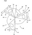
- FIG. 1 a finished threaded blind hole 1 is shown.
- the bore 1 is incorporated with its bottom hole 3 to a desired drilling depth t B in a workpiece 5 by means of a so-called bullet drilling, which will be described later with reference to FIGS. 5 to 8 is explained.
- the bore 1 has at its bore opening a circumferential thread counterbore 7, which merges in the further course down into an internal thread 9.
- the internal thread 9 extends along the bore axis A to a usable nominal thread depth t G.
- a thread 15 of the internal thread 9 opens with a threaded outlet 11 in a Umlaufnut 13. This has no thread pitch and, viewed in the axial direction, between the internal thread 9 and the bottom of the hole 3 is formed.
- the thread 15 has a radially outer thread base 17 and lateral thread flanks 19, which merge radially inward into a threaded inner vertex 21.
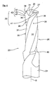
- FIG. 1 shown threaded blind hole 1 hole is using a reference to the FIGS. 2 to 4 described tapping tool 23 performed. Consequently, the tool 23 in the FIG. 2 at its drill tip 25 three evenly circumferentially distributed, frontal Main cutting edge 27 and one in the tapping direction I ( FIG. 5 or 6 ) trailing thread profile 29.
- the tool 23 is constructed with a clamping shank 24 and a subsequent tapping body 26, along the bore axis A, a total of three circumferentially distributed flutes 28 extend to the respective end-side main cutting edge 27 on the drill bit 25.
- a flute surface 28 delimiting the flute 28 and a face-side flank 33 of the drill point 25 converge.
- the respective flute 28 is bounded by a drill land 35.
- the tapping tool 23 shown in the figures has three drill webs 35.
- the rake face 31 of the flute 28 thereby goes over to form an auxiliary cutting edge 36 in an outer peripheral side backing surface 37 of the respective drill web 35.
- the secondary cutting edge 36 and the frontal main cutting edge 27 converge at a radially outer main cutting corner 39.
- the thread profile 29 in each case a Vorschneid leopard 41, a central cutting tooth 42 and a finished cutting tooth 43.
- Each of the cutting teeth 41, 42, 43 is formed with a radially outer thread root cutting edge 45 and thread flank cutting edges 47 in order to use the FIG. 1 shown thread 15 to cut / shape.
- the cutting teeth 41 to 43 are designed in different geometries and with different axial distances .DELTA.a (only in the FIG. 5 indicated) spaced from the drill bit 25 to the in the FIG. 1 shown thread 15 of the internal thread 9 to cut.
- the pre-cutting, centering and finishing cutting teeth 41, 42, 43 have different axial dimensions in the axial direction and / or different tooth heights ⁇ r (in the radial direction) Fig. 2 ) exhibit.
- the preliminary, middle and finished cutting teeth 41, 42, 43 can become axially larger in the circumferential direction.
- the finished cutting tooth 43 then cuts the entire internal thread contour.
- the finish cutting tooth 43 may also be designed as a form tooth to increase the thread strength.
- the tapping tool 23 also has at the transition between the tapping body 26 and the clamping shank 24 a cutting edge 49 to form the in the FIG. 1 shown thread counterbore 7.
- the tapping tool 23 is guided in a tapping direction I on the not pre-drilled tool 5 and performed a bullet hole.
- a tapping stroke G the main cutting edges 27 produce a core hole and at the same time the trailing thread profile 29, the internal thread 9 on the inner wall of the core hole.
- the tapping stroke G takes place at a tapping feed rate f G and at a synchronized tapping speed n G in a tapping rotational direction, namely until the nominal thread depth t G is reached ( FIG. 6 ).
- a groove forming step ( FIG. 7 ), in which the tapping stroke G in the tapping direction I is extended by a groove shape stroke N.
- the groove-shape feed f N and the groove-shape rotational speed n N of the tapping tool 23 are not synchronized with one another in the groove-forming stroke H, and also different from the previous tapping feed f G and the tapping speed n G.
- the thread profile 29 generates with its pre-, middle and finished cutting teeth 41, 42, 43 in the FIG. 7 shown Umlaufnut 13 in which the thread profile 29 can rotate without load.
- the groove-shape feed f N and the groove-shape rotational speed n N are designed so that an excessively large cutting load of the cutting teeth 41 to 43 is prevented.
- both the slot shape feed f N and the slot shape speed n N are reduced to 0.
- a reversal of direction in preparation for a reversing stroke R ( FIG. 8 ) a reversal of direction.
- the tapping tool 23 is in a reversing direction II ( FIG. 8 ) led out of the threaded hole 1, with an opposite reversing feed f R and thus synchronized reversing speed n R.
- the tapping tool 23 When starting the reversing stroke R, the tapping tool 23 is controlled by the manufacturing plant so that the cutting teeth 41, 42, 43 each free of load in the thread outlet 11, which opens into the circumferential groove 13, retracted. In the further course of the reversing stroke R, the thread profile 29 of the tapping tool 23 is then rotated without load through the thread 15 of the internal thread 9 to the outside.
Landscapes
- Engineering & Computer Science (AREA)
- Mechanical Engineering (AREA)
- Drilling Tools (AREA)
- Numerical Control (AREA)
Applications Claiming Priority (2)
| Application Number | Priority Date | Filing Date | Title |
|---|---|---|---|
| DE102016008478.2A DE102016008478B4 (de) | 2016-07-13 | 2016-07-13 | Verfahren zur Erzeugung einer Gewindebohrung |
| PCT/EP2017/000751 WO2018010830A1 (de) | 2016-07-13 | 2017-06-27 | Verfahren zur erzeugung einer gewindebohrung |
Publications (2)
| Publication Number | Publication Date |
|---|---|
| EP3484647A1 EP3484647A1 (de) | 2019-05-22 |
| EP3484647B1 true EP3484647B1 (de) | 2019-10-09 |
Family
ID=59239883
Family Applications (1)
| Application Number | Title | Priority Date | Filing Date |
|---|---|---|---|
| EP17733736.7A Active EP3484647B1 (de) | 2016-07-13 | 2017-06-27 | Verfahren zur erzeugung einer gewindebohrung und werkzeug für dieses verfahren |
Country Status (8)
| Country | Link |
|---|---|
| US (1) | US10632553B2 (enExample) |
| EP (1) | EP3484647B1 (enExample) |
| JP (1) | JP6625263B2 (enExample) |
| CN (1) | CN109475956B (enExample) |
| DE (1) | DE102016008478B4 (enExample) |
| ES (1) | ES2753812T3 (enExample) |
| HU (1) | HUE046826T2 (enExample) |
| WO (1) | WO2018010830A1 (enExample) |
Cited By (2)
| Publication number | Priority date | Publication date | Assignee | Title |
|---|---|---|---|---|
| DE102020108679A1 (de) | 2020-03-30 | 2021-09-30 | Audi Aktiengesellschaft | Gewindebohr-Werkzeug und Verfahren zur Erzeugung einer Gewindebohrung |
| DE102020109815A1 (de) | 2020-04-08 | 2021-10-14 | Audi Aktiengesellschaft | Verfahren zur Erzeugung einer Werkstück-Gewindebohrung |
Families Citing this family (13)
| Publication number | Priority date | Publication date | Assignee | Title |
|---|---|---|---|---|
| DE102018206543B4 (de) * | 2018-04-27 | 2021-08-12 | Audi Ag | Gewindebohr-Werkzeug und Verfahren zur Erzeugung einer Gewindebohrung |
| DE102018206545B4 (de) * | 2018-04-27 | 2021-10-14 | Audi Ag | Gewindebohr-Werkzeug und Verfahren zur Erzeugung einer Gewindebohrung |
| WO2019238175A1 (de) | 2018-06-15 | 2019-12-19 | EMUGE-Werk Richard Glimpel GmbH & Co. KG Fabrik für Präzisionswerkzeuge | Verfahren zum erzeugen eines innengewindes |
| DE102018115986A1 (de) | 2018-07-02 | 2020-01-02 | EMUGE-Werk Richard Glimpel GmbH & Co. KG Fabrik für Präzisionswerkzeuge | Werkzeug zum Erzeugen eines Gewindes |
| DE102018220397A1 (de) * | 2018-11-28 | 2020-06-10 | Audi Ag | Gewindebohr-Werkzeug und Verfahren zur Erzeugung einer Gewindebohrung |
| EP3921106A1 (de) | 2019-02-08 | 2021-12-15 | EMUGE-Werk Richard Glimpel GmbH & Co.KG Fabrik für Präzisionswerkzeuge | Werkzeug und verfahren zum erzeugen eines gewindelochs mit spanteilern |
| DE102019123625B4 (de) * | 2019-09-04 | 2021-12-16 | Audi Ag | Gewindebohr-Werkzeug sowie Verfahren zur Erzeugung einer Werkstück-Gewindebohrung |
| DE102019124679A1 (de) * | 2019-09-13 | 2021-03-18 | EMUGE-Werk Richard Glimpel GmbH & Co. KG Fabrik für Präzisionswerkzeuge | Verfahren zum Erzeugen eines Durchgangsgewindes |
| DE102019124707B4 (de) | 2019-09-13 | 2022-05-19 | EMUGE-Werk Richard Glimpel GmbH & Co. KG Fabrik für Präzisionswerkzeuge | Verfahren zum Erzeugen eines Gewindes mit Übersetzungseinheit |
| DE102019124800B4 (de) | 2019-09-16 | 2024-09-19 | EMUGE-Werk Richard Glimpel GmbH & Co. KG Fabrik für Präzisionswerkzeuge | Verfahren zum Erzeugen eines Gewindes, insbesondere eines Innengewindes, mit Hartmetall |
| DE102020100853B4 (de) * | 2020-01-15 | 2024-03-28 | Audi Aktiengesellschaft | Verfahren zur Erzeugung einer Durchgangs-Gewindebohrung in einem Werkstück |
| DE102021103992A1 (de) | 2021-02-19 | 2022-08-25 | EMUGE-Werk Richard Glimpel GmbH & Co. KG Fabrik für Präzisionswerkzeuge | Werkzeugkoppelvorrichtung mit Übersetzungseinheit und Verfahren zum Erzeugen eines Gewindes oder eines Gewindelochs |
| DE102022115490A1 (de) * | 2022-06-22 | 2023-12-28 | Kennametal Inc. | Rotationsbohrwerkzeug sowie Verfahren zum Herstellen einer Durchgangsbohrung |
Citations (1)
| Publication number | Priority date | Publication date | Assignee | Title |
|---|---|---|---|---|
| DE1818609U (de) * | 1960-07-22 | 1960-09-22 | Erwin Geister | Bohrer. |
Family Cites Families (21)
| Publication number | Priority date | Publication date | Assignee | Title |
|---|---|---|---|---|
| US4271554A (en) * | 1979-01-09 | 1981-06-09 | Allen-Stevens Corp. | Combination drill and tap tool |
| US5413438A (en) * | 1986-03-17 | 1995-05-09 | Turchan; Manuel C. | Combined hole making and threading tool |
| US4761844A (en) * | 1986-03-17 | 1988-08-09 | Turchan Manuel C | Combined hole making and threading tool |
| US4651374A (en) * | 1986-03-17 | 1987-03-24 | Turchan Manuel C | Combined hole making and threading tool |
| DE3828780A1 (de) * | 1988-08-25 | 1990-03-01 | Schmitt M Norbert Dipl Kaufm D | Bohrgewindefraeser |
| DE3921734C2 (de) * | 1989-07-01 | 1995-09-14 | Schmitt M Norbert Dipl Kaufm D | Gewindefräsbohrwerkzeug mit Zahnungskerben |
| DE3939795A1 (de) * | 1989-12-01 | 1991-06-06 | Schmitt M Norbert Dipl Kaufm D | Verfahren zur herstellung einer gewindebohrung |
| JPH06114631A (ja) | 1992-09-29 | 1994-04-26 | O S G Kk | 穿孔刃付き多山テーパねじフライスおよびその使用方法 |
| US5678962A (en) * | 1994-09-06 | 1997-10-21 | Makino Inc. | Integral boring and threading tool and method |
| US6012882A (en) * | 1995-09-12 | 2000-01-11 | Turchan; Manuel C. | Combined hole making, threading, and chamfering tool with staggered thread cutting teeth |
| DE19651425A1 (de) * | 1996-12-11 | 1998-06-18 | Link Johann & Ernst Gmbh & Co | Gewindefräser |
| JPH11170114A (ja) * | 1997-12-11 | 1999-06-29 | Honda Motor Co Ltd | ドリル刃付きねじ切りフライス |
| CA2309289C (en) * | 1999-05-24 | 2007-10-30 | Honda Giken Kogyo Kabushiki Kaisha | Cutting tip and manufacturing method thereof |
| DE10061476A1 (de) | 2000-12-08 | 2002-06-13 | Voelkel Gmbh | Gewindebohrer zur Herstellung eines Außengewindes |
| DE10334454B3 (de) * | 2002-08-10 | 2005-05-12 | Felix Leeb | Bohrgewindefräser welcher sich auch zum Einsatz bei Stahl eignet |
| DE10332930A1 (de) * | 2003-07-19 | 2005-02-03 | Sandvik Ab | Gewindebohrer |
| JP2005230933A (ja) * | 2004-02-17 | 2005-09-02 | Aisin Seiki Co Ltd | ねじ穴加工用工具 |
| JP4703149B2 (ja) | 2004-09-17 | 2011-06-15 | マキノジェイ株式会社 | ねじ穴加工方法 |
| SE530788C2 (sv) * | 2007-01-17 | 2008-09-09 | Sandvik Intellectual Property | Roterbart fleroperationsverktyg för spånavskiljande bearbetning, samt grundkropp härför |
| DE102012105183B4 (de) * | 2012-06-14 | 2013-12-24 | Audi Ag | Verfahren und ein Werkzeug jeweils zum Erzeugen eines Gewindes in einem Werkstück |
| DE102017007419B4 (de) * | 2017-08-05 | 2021-08-12 | Audi Ag | Verfahren zur Erzeugung einer Gewindebohrung |
-
2016
- 2016-07-13 DE DE102016008478.2A patent/DE102016008478B4/de not_active Expired - Fee Related
-
2017
- 2017-06-27 CN CN201780043304.8A patent/CN109475956B/zh active Active
- 2017-06-27 ES ES17733736T patent/ES2753812T3/es active Active
- 2017-06-27 WO PCT/EP2017/000751 patent/WO2018010830A1/de not_active Ceased
- 2017-06-27 EP EP17733736.7A patent/EP3484647B1/de active Active
- 2017-06-27 US US16/317,238 patent/US10632553B2/en active Active
- 2017-06-27 JP JP2019501957A patent/JP6625263B2/ja active Active
- 2017-06-27 HU HUE17733736A patent/HUE046826T2/hu unknown
Patent Citations (1)
| Publication number | Priority date | Publication date | Assignee | Title |
|---|---|---|---|---|
| DE1818609U (de) * | 1960-07-22 | 1960-09-22 | Erwin Geister | Bohrer. |
Cited By (5)
| Publication number | Priority date | Publication date | Assignee | Title |
|---|---|---|---|---|
| DE102020108679A1 (de) | 2020-03-30 | 2021-09-30 | Audi Aktiengesellschaft | Gewindebohr-Werkzeug und Verfahren zur Erzeugung einer Gewindebohrung |
| WO2021197697A1 (de) | 2020-03-30 | 2021-10-07 | Audi Ag | Gewindebohr-werkzeug und verfahren zur erzeugung einer gewindebohrung |
| DE102020108679B4 (de) | 2020-03-30 | 2022-09-29 | Audi Aktiengesellschaft | Gewindebohr-Werkzeug zur Erzeugung einer Gewindebohrung |
| DE102020109815A1 (de) | 2020-04-08 | 2021-10-14 | Audi Aktiengesellschaft | Verfahren zur Erzeugung einer Werkstück-Gewindebohrung |
| DE102020109815B4 (de) | 2020-04-08 | 2022-11-24 | Audi Aktiengesellschaft | Verfahren und Gewindeerzeugungs-Werkzeug zur Erzeugung einer Werkstück-Gewindebohrung |
Also Published As
| Publication number | Publication date |
|---|---|
| DE102016008478A1 (de) | 2018-01-18 |
| DE102016008478B4 (de) | 2020-10-15 |
| CN109475956B (zh) | 2019-11-29 |
| WO2018010830A1 (de) | 2018-01-18 |
| US10632553B2 (en) | 2020-04-28 |
| US20190337060A1 (en) | 2019-11-07 |
| EP3484647A1 (de) | 2019-05-22 |
| ES2753812T3 (es) | 2020-04-14 |
| HUE046826T2 (hu) | 2020-03-30 |
| JP2019520996A (ja) | 2019-07-25 |
| CN109475956A (zh) | 2019-03-15 |
| JP6625263B2 (ja) | 2019-12-25 |
Similar Documents
| Publication | Publication Date | Title |
|---|---|---|
| EP3484647B1 (de) | Verfahren zur erzeugung einer gewindebohrung und werkzeug für dieses verfahren | |
| EP3458219B1 (de) | Verfahren zur erzeugung einer gewindebohrung sowie gewindebohr-werkzeug | |
| EP3433044B1 (de) | Verfahren und werkzeug zur erzeugung einer gewindebohrung | |
| EP3471908B1 (de) | Werkzeug zur erzeugung eines innengewindes in einer werkstück-vorbohrung | |
| EP3784430B1 (de) | Gewindebohr-werkzeug und verfahren zur erzeugung einer gewindebohrung | |
| DE102020109035B4 (de) | Verfahren und Gewindebohr-Werkzeug zur Erzeugung einer Werkstück-Gewindebohrung | |
| EP3204180B1 (de) | Bohrwerkzeug, insbesondere reibahle | |
| EP3887084B1 (de) | Gewindebohr-werkzeug und verfahren zur erzeugung einer gewindebohrung | |
| DE102018206540B4 (de) | Gewindebohr-Werkzeug und Verfahren zur Erzeugung einer Gewindebohrung | |
| EP3142819B1 (de) | Werkzeug zum aufrauen einer metallischen oberfläche und verfahren zum aufrauen einer mettalischen oberfläche mit einem solchen aufrauwerkzeug | |
| EP3908420B1 (de) | Gewindebohr-werkzeug zur erzeugung einer gewindebohrung | |
| EP4025369B1 (de) | Verfahren zur erzeugung einer werkstück-gewindebohrung | |
| DE102018206543B4 (de) | Gewindebohr-Werkzeug und Verfahren zur Erzeugung einer Gewindebohrung |
Legal Events
| Date | Code | Title | Description |
|---|---|---|---|
| STAA | Information on the status of an ep patent application or granted ep patent |
Free format text: STATUS: UNKNOWN |
|
| STAA | Information on the status of an ep patent application or granted ep patent |
Free format text: STATUS: THE INTERNATIONAL PUBLICATION HAS BEEN MADE |
|
| PUAI | Public reference made under article 153(3) epc to a published international application that has entered the european phase |
Free format text: ORIGINAL CODE: 0009012 |
|
| STAA | Information on the status of an ep patent application or granted ep patent |
Free format text: STATUS: REQUEST FOR EXAMINATION WAS MADE |
|
| 17P | Request for examination filed |
Effective date: 20190213 |
|
| AK | Designated contracting states |
Kind code of ref document: A1 Designated state(s): AL AT BE BG CH CY CZ DE DK EE ES FI FR GB GR HR HU IE IS IT LI LT LU LV MC MK MT NL NO PL PT RO RS SE SI SK SM TR |
|
| AX | Request for extension of the european patent |
Extension state: BA ME |
|
| GRAP | Despatch of communication of intention to grant a patent |
Free format text: ORIGINAL CODE: EPIDOSNIGR1 |
|
| STAA | Information on the status of an ep patent application or granted ep patent |
Free format text: STATUS: GRANT OF PATENT IS INTENDED |
|
| GRAS | Grant fee paid |
Free format text: ORIGINAL CODE: EPIDOSNIGR3 |
|
| DAV | Request for validation of the european patent (deleted) | ||
| DAX | Request for extension of the european patent (deleted) | ||
| INTG | Intention to grant announced |
Effective date: 20190805 |
|
| GRAA | (expected) grant |
Free format text: ORIGINAL CODE: 0009210 |
|
| STAA | Information on the status of an ep patent application or granted ep patent |
Free format text: STATUS: THE PATENT HAS BEEN GRANTED |
|
| AK | Designated contracting states |
Kind code of ref document: B1 Designated state(s): AL AT BE BG CH CY CZ DE DK EE ES FI FR GB GR HR HU IE IS IT LI LT LU LV MC MK MT NL NO PL PT RO RS SE SI SK SM TR |
|
| REG | Reference to a national code |
Ref country code: GB Ref legal event code: FG4D Free format text: NOT ENGLISH |
|
| REG | Reference to a national code |
Ref country code: CH Ref legal event code: EP |
|
| REG | Reference to a national code |
Ref country code: IE Ref legal event code: FG4D Free format text: LANGUAGE OF EP DOCUMENT: GERMAN |
|
| REG | Reference to a national code |
Ref country code: DE Ref legal event code: R096 Ref document number: 502017002537 Country of ref document: DE |
|
| REG | Reference to a national code |
Ref country code: AT Ref legal event code: REF Ref document number: 1188205 Country of ref document: AT Kind code of ref document: T Effective date: 20191115 |
|
| REG | Reference to a national code |
Ref country code: NL Ref legal event code: MP Effective date: 20191009 |
|
| REG | Reference to a national code |
Ref country code: LT Ref legal event code: MG4D |
|
| REG | Reference to a national code |
Ref country code: HU Ref legal event code: AG4A Ref document number: E046826 Country of ref document: HU |
|
| REG | Reference to a national code |
Ref country code: ES Ref legal event code: FG2A Ref document number: 2753812 Country of ref document: ES Kind code of ref document: T3 Effective date: 20200414 |
|
| PG25 | Lapsed in a contracting state [announced via postgrant information from national office to epo] |
Ref country code: PT Free format text: LAPSE BECAUSE OF FAILURE TO SUBMIT A TRANSLATION OF THE DESCRIPTION OR TO PAY THE FEE WITHIN THE PRESCRIBED TIME-LIMIT Effective date: 20200210 Ref country code: GR Free format text: LAPSE BECAUSE OF FAILURE TO SUBMIT A TRANSLATION OF THE DESCRIPTION OR TO PAY THE FEE WITHIN THE PRESCRIBED TIME-LIMIT Effective date: 20200110 Ref country code: NL Free format text: LAPSE BECAUSE OF FAILURE TO SUBMIT A TRANSLATION OF THE DESCRIPTION OR TO PAY THE FEE WITHIN THE PRESCRIBED TIME-LIMIT Effective date: 20191009 Ref country code: BG Free format text: LAPSE BECAUSE OF FAILURE TO SUBMIT A TRANSLATION OF THE DESCRIPTION OR TO PAY THE FEE WITHIN THE PRESCRIBED TIME-LIMIT Effective date: 20200109 Ref country code: FI Free format text: LAPSE BECAUSE OF FAILURE TO SUBMIT A TRANSLATION OF THE DESCRIPTION OR TO PAY THE FEE WITHIN THE PRESCRIBED TIME-LIMIT Effective date: 20191009 Ref country code: NO Free format text: LAPSE BECAUSE OF FAILURE TO SUBMIT A TRANSLATION OF THE DESCRIPTION OR TO PAY THE FEE WITHIN THE PRESCRIBED TIME-LIMIT Effective date: 20200109 Ref country code: PL Free format text: LAPSE BECAUSE OF FAILURE TO SUBMIT A TRANSLATION OF THE DESCRIPTION OR TO PAY THE FEE WITHIN THE PRESCRIBED TIME-LIMIT Effective date: 20191009 Ref country code: LT Free format text: LAPSE BECAUSE OF FAILURE TO SUBMIT A TRANSLATION OF THE DESCRIPTION OR TO PAY THE FEE WITHIN THE PRESCRIBED TIME-LIMIT Effective date: 20191009 Ref country code: SE Free format text: LAPSE BECAUSE OF FAILURE TO SUBMIT A TRANSLATION OF THE DESCRIPTION OR TO PAY THE FEE WITHIN THE PRESCRIBED TIME-LIMIT Effective date: 20191009 Ref country code: LV Free format text: LAPSE BECAUSE OF FAILURE TO SUBMIT A TRANSLATION OF THE DESCRIPTION OR TO PAY THE FEE WITHIN THE PRESCRIBED TIME-LIMIT Effective date: 20191009 |
|
| PG25 | Lapsed in a contracting state [announced via postgrant information from national office to epo] |
Ref country code: HR Free format text: LAPSE BECAUSE OF FAILURE TO SUBMIT A TRANSLATION OF THE DESCRIPTION OR TO PAY THE FEE WITHIN THE PRESCRIBED TIME-LIMIT Effective date: 20191009 Ref country code: RS Free format text: LAPSE BECAUSE OF FAILURE TO SUBMIT A TRANSLATION OF THE DESCRIPTION OR TO PAY THE FEE WITHIN THE PRESCRIBED TIME-LIMIT Effective date: 20191009 Ref country code: IS Free format text: LAPSE BECAUSE OF FAILURE TO SUBMIT A TRANSLATION OF THE DESCRIPTION OR TO PAY THE FEE WITHIN THE PRESCRIBED TIME-LIMIT Effective date: 20200224 |
|
| PG25 | Lapsed in a contracting state [announced via postgrant information from national office to epo] |
Ref country code: AL Free format text: LAPSE BECAUSE OF FAILURE TO SUBMIT A TRANSLATION OF THE DESCRIPTION OR TO PAY THE FEE WITHIN THE PRESCRIBED TIME-LIMIT Effective date: 20191009 |
|
| REG | Reference to a national code |
Ref country code: DE Ref legal event code: R097 Ref document number: 502017002537 Country of ref document: DE |
|
| PG2D | Information on lapse in contracting state deleted |
Ref country code: IS |
|
| PG25 | Lapsed in a contracting state [announced via postgrant information from national office to epo] |
Ref country code: RO Free format text: LAPSE BECAUSE OF FAILURE TO SUBMIT A TRANSLATION OF THE DESCRIPTION OR TO PAY THE FEE WITHIN THE PRESCRIBED TIME-LIMIT Effective date: 20191009 Ref country code: CZ Free format text: LAPSE BECAUSE OF FAILURE TO SUBMIT A TRANSLATION OF THE DESCRIPTION OR TO PAY THE FEE WITHIN THE PRESCRIBED TIME-LIMIT Effective date: 20191009 Ref country code: DK Free format text: LAPSE BECAUSE OF FAILURE TO SUBMIT A TRANSLATION OF THE DESCRIPTION OR TO PAY THE FEE WITHIN THE PRESCRIBED TIME-LIMIT Effective date: 20191009 Ref country code: EE Free format text: LAPSE BECAUSE OF FAILURE TO SUBMIT A TRANSLATION OF THE DESCRIPTION OR TO PAY THE FEE WITHIN THE PRESCRIBED TIME-LIMIT Effective date: 20191009 Ref country code: IS Free format text: LAPSE BECAUSE OF FAILURE TO SUBMIT A TRANSLATION OF THE DESCRIPTION OR TO PAY THE FEE WITHIN THE PRESCRIBED TIME-LIMIT Effective date: 20200209 |
|
| PLBE | No opposition filed within time limit |
Free format text: ORIGINAL CODE: 0009261 |
|
| STAA | Information on the status of an ep patent application or granted ep patent |
Free format text: STATUS: NO OPPOSITION FILED WITHIN TIME LIMIT |
|
| PG25 | Lapsed in a contracting state [announced via postgrant information from national office to epo] |
Ref country code: SM Free format text: LAPSE BECAUSE OF FAILURE TO SUBMIT A TRANSLATION OF THE DESCRIPTION OR TO PAY THE FEE WITHIN THE PRESCRIBED TIME-LIMIT Effective date: 20191009 Ref country code: SK Free format text: LAPSE BECAUSE OF FAILURE TO SUBMIT A TRANSLATION OF THE DESCRIPTION OR TO PAY THE FEE WITHIN THE PRESCRIBED TIME-LIMIT Effective date: 20191009 |
|
| 26N | No opposition filed |
Effective date: 20200710 |
|
| PG25 | Lapsed in a contracting state [announced via postgrant information from national office to epo] |
Ref country code: MC Free format text: LAPSE BECAUSE OF FAILURE TO SUBMIT A TRANSLATION OF THE DESCRIPTION OR TO PAY THE FEE WITHIN THE PRESCRIBED TIME-LIMIT Effective date: 20191009 |
|
| REG | Reference to a national code |
Ref country code: CH Ref legal event code: PL |
|
| PG25 | Lapsed in a contracting state [announced via postgrant information from national office to epo] |
Ref country code: SI Free format text: LAPSE BECAUSE OF FAILURE TO SUBMIT A TRANSLATION OF THE DESCRIPTION OR TO PAY THE FEE WITHIN THE PRESCRIBED TIME-LIMIT Effective date: 20191009 |
|
| PG25 | Lapsed in a contracting state [announced via postgrant information from national office to epo] |
Ref country code: LU Free format text: LAPSE BECAUSE OF NON-PAYMENT OF DUE FEES Effective date: 20200627 |
|
| REG | Reference to a national code |
Ref country code: BE Ref legal event code: MM Effective date: 20200630 |
|
| PG25 | Lapsed in a contracting state [announced via postgrant information from national office to epo] |
Ref country code: CH Free format text: LAPSE BECAUSE OF NON-PAYMENT OF DUE FEES Effective date: 20200630 Ref country code: LI Free format text: LAPSE BECAUSE OF NON-PAYMENT OF DUE FEES Effective date: 20200630 Ref country code: IE Free format text: LAPSE BECAUSE OF NON-PAYMENT OF DUE FEES Effective date: 20200627 |
|
| PG25 | Lapsed in a contracting state [announced via postgrant information from national office to epo] |
Ref country code: BE Free format text: LAPSE BECAUSE OF NON-PAYMENT OF DUE FEES Effective date: 20200630 |
|
| PG25 | Lapsed in a contracting state [announced via postgrant information from national office to epo] |
Ref country code: TR Free format text: LAPSE BECAUSE OF FAILURE TO SUBMIT A TRANSLATION OF THE DESCRIPTION OR TO PAY THE FEE WITHIN THE PRESCRIBED TIME-LIMIT Effective date: 20191009 Ref country code: MT Free format text: LAPSE BECAUSE OF FAILURE TO SUBMIT A TRANSLATION OF THE DESCRIPTION OR TO PAY THE FEE WITHIN THE PRESCRIBED TIME-LIMIT Effective date: 20191009 Ref country code: CY Free format text: LAPSE BECAUSE OF FAILURE TO SUBMIT A TRANSLATION OF THE DESCRIPTION OR TO PAY THE FEE WITHIN THE PRESCRIBED TIME-LIMIT Effective date: 20191009 |
|
| PG25 | Lapsed in a contracting state [announced via postgrant information from national office to epo] |
Ref country code: MK Free format text: LAPSE BECAUSE OF FAILURE TO SUBMIT A TRANSLATION OF THE DESCRIPTION OR TO PAY THE FEE WITHIN THE PRESCRIBED TIME-LIMIT Effective date: 20191009 |
|
| P01 | Opt-out of the competence of the unified patent court (upc) registered |
Effective date: 20230530 |
|
| REG | Reference to a national code |
Ref country code: AT Ref legal event code: MM01 Ref document number: 1188205 Country of ref document: AT Kind code of ref document: T Effective date: 20220627 |
|
| PG25 | Lapsed in a contracting state [announced via postgrant information from national office to epo] |
Ref country code: AT Free format text: LAPSE BECAUSE OF NON-PAYMENT OF DUE FEES Effective date: 20220627 |
|
| PGFP | Annual fee paid to national office [announced via postgrant information from national office to epo] |
Ref country code: DE Payment date: 20250630 Year of fee payment: 9 |
|
| PGFP | Annual fee paid to national office [announced via postgrant information from national office to epo] |
Ref country code: GB Payment date: 20250621 Year of fee payment: 9 |
|
| PGFP | Annual fee paid to national office [announced via postgrant information from national office to epo] |
Ref country code: HU Payment date: 20250530 Year of fee payment: 9 Ref country code: FR Payment date: 20250617 Year of fee payment: 9 |
|
| PGFP | Annual fee paid to national office [announced via postgrant information from national office to epo] |
Ref country code: ES Payment date: 20250701 Year of fee payment: 9 |
|
| PGFP | Annual fee paid to national office [announced via postgrant information from national office to epo] |
Ref country code: IT Payment date: 20250627 Year of fee payment: 9 |