EP3484108B1 - Procédé de distribution de données sur un réseau - Google Patents
Procédé de distribution de données sur un réseau Download PDFInfo
- Publication number
- EP3484108B1 EP3484108B1 EP18188902.3A EP18188902A EP3484108B1 EP 3484108 B1 EP3484108 B1 EP 3484108B1 EP 18188902 A EP18188902 A EP 18188902A EP 3484108 B1 EP3484108 B1 EP 3484108B1
- Authority
- EP
- European Patent Office
- Prior art keywords
- network
- network element
- congestion
- link
- data packet
- Prior art date
- Legal status (The legal status is an assumption and is not a legal conclusion. Google has not performed a legal analysis and makes no representation as to the accuracy of the status listed.)
- Active
Links
Images


Classifications
-
- H—ELECTRICITY
- H04—ELECTRIC COMMUNICATION TECHNIQUE
- H04L—TRANSMISSION OF DIGITAL INFORMATION, e.g. TELEGRAPHIC COMMUNICATION
- H04L43/00—Arrangements for monitoring or testing data switching networks
- H04L43/08—Monitoring or testing based on specific metrics, e.g. QoS, energy consumption or environmental parameters
- H04L43/0876—Network utilisation, e.g. volume of load or congestion level
-
- H—ELECTRICITY
- H04—ELECTRIC COMMUNICATION TECHNIQUE
- H04L—TRANSMISSION OF DIGITAL INFORMATION, e.g. TELEGRAPHIC COMMUNICATION
- H04L47/00—Traffic control in data switching networks
- H04L47/10—Flow control; Congestion control
- H04L47/12—Avoiding congestion; Recovering from congestion
- H04L47/122—Avoiding congestion; Recovering from congestion by diverting traffic away from congested entities
-
- H—ELECTRICITY
- H04—ELECTRIC COMMUNICATION TECHNIQUE
- H04L—TRANSMISSION OF DIGITAL INFORMATION, e.g. TELEGRAPHIC COMMUNICATION
- H04L45/00—Routing or path finding of packets in data switching networks
- H04L45/12—Shortest path evaluation
- H04L45/125—Shortest path evaluation based on throughput or bandwidth
-
- H—ELECTRICITY
- H04—ELECTRIC COMMUNICATION TECHNIQUE
- H04L—TRANSMISSION OF DIGITAL INFORMATION, e.g. TELEGRAPHIC COMMUNICATION
- H04L45/00—Routing or path finding of packets in data switching networks
-
- H—ELECTRICITY
- H04—ELECTRIC COMMUNICATION TECHNIQUE
- H04L—TRANSMISSION OF DIGITAL INFORMATION, e.g. TELEGRAPHIC COMMUNICATION
- H04L45/00—Routing or path finding of packets in data switching networks
- H04L45/22—Alternate routing
-
- H—ELECTRICITY
- H04—ELECTRIC COMMUNICATION TECHNIQUE
- H04L—TRANSMISSION OF DIGITAL INFORMATION, e.g. TELEGRAPHIC COMMUNICATION
- H04L45/00—Routing or path finding of packets in data switching networks
- H04L45/24—Multipath
-
- H—ELECTRICITY
- H04—ELECTRIC COMMUNICATION TECHNIQUE
- H04L—TRANSMISSION OF DIGITAL INFORMATION, e.g. TELEGRAPHIC COMMUNICATION
- H04L47/00—Traffic control in data switching networks
- H04L47/10—Flow control; Congestion control
- H04L47/11—Identifying congestion
-
- H—ELECTRICITY
- H04—ELECTRIC COMMUNICATION TECHNIQUE
- H04L—TRANSMISSION OF DIGITAL INFORMATION, e.g. TELEGRAPHIC COMMUNICATION
- H04L47/00—Traffic control in data switching networks
- H04L47/10—Flow control; Congestion control
- H04L47/31—Flow control; Congestion control by tagging of packets, e.g. using discard eligibility [DE] bits
-
- H—ELECTRICITY
- H04—ELECTRIC COMMUNICATION TECHNIQUE
- H04L—TRANSMISSION OF DIGITAL INFORMATION, e.g. TELEGRAPHIC COMMUNICATION
- H04L47/00—Traffic control in data switching networks
- H04L47/50—Queue scheduling
- H04L47/56—Queue scheduling implementing delay-aware scheduling
-
- H—ELECTRICITY
- H04—ELECTRIC COMMUNICATION TECHNIQUE
- H04L—TRANSMISSION OF DIGITAL INFORMATION, e.g. TELEGRAPHIC COMMUNICATION
- H04L49/00—Packet switching elements
- H04L49/50—Overload detection or protection within a single switching element
- H04L49/501—Overload detection
-
- H—ELECTRICITY
- H04—ELECTRIC COMMUNICATION TECHNIQUE
- H04L—TRANSMISSION OF DIGITAL INFORMATION, e.g. TELEGRAPHIC COMMUNICATION
- H04L12/00—Data switching networks
- H04L12/54—Store-and-forward switching systems
- H04L12/56—Packet switching systems
- H04L12/5601—Transfer mode dependent, e.g. ATM
- H04L2012/5678—Traffic aspects, e.g. arbitration, load balancing, smoothing, buffer management
- H04L2012/5681—Buffer or queue management
- H04L2012/5682—Threshold; Watermark
-
- H—ELECTRICITY
- H04—ELECTRIC COMMUNICATION TECHNIQUE
- H04L—TRANSMISSION OF DIGITAL INFORMATION, e.g. TELEGRAPHIC COMMUNICATION
- H04L43/00—Arrangements for monitoring or testing data switching networks
- H04L43/16—Threshold monitoring
-
- H—ELECTRICITY
- H04—ELECTRIC COMMUNICATION TECHNIQUE
- H04L—TRANSMISSION OF DIGITAL INFORMATION, e.g. TELEGRAPHIC COMMUNICATION
- H04L49/00—Packet switching elements
- H04L49/10—Packet switching elements characterised by the switching fabric construction
- H04L49/101—Packet switching elements characterised by the switching fabric construction using crossbar or matrix
-
- H—ELECTRICITY
- H04—ELECTRIC COMMUNICATION TECHNIQUE
- H04L—TRANSMISSION OF DIGITAL INFORMATION, e.g. TELEGRAPHIC COMMUNICATION
- H04L49/00—Packet switching elements
- H04L49/15—Interconnection of switching modules
- H04L49/1515—Non-blocking multistage, e.g. Clos
-
- H—ELECTRICITY
- H04—ELECTRIC COMMUNICATION TECHNIQUE
- H04L—TRANSMISSION OF DIGITAL INFORMATION, e.g. TELEGRAPHIC COMMUNICATION
- H04L49/00—Packet switching elements
- H04L49/25—Routing or path finding in a switch fabric
- H04L49/253—Routing or path finding in a switch fabric using establishment or release of connections between ports
-
- H—ELECTRICITY
- H04—ELECTRIC COMMUNICATION TECHNIQUE
- H04L—TRANSMISSION OF DIGITAL INFORMATION, e.g. TELEGRAPHIC COMMUNICATION
- H04L49/00—Packet switching elements
- H04L49/30—Peripheral units, e.g. input or output ports
- H04L49/3018—Input queuing
-
- H—ELECTRICITY
- H04—ELECTRIC COMMUNICATION TECHNIQUE
- H04L—TRANSMISSION OF DIGITAL INFORMATION, e.g. TELEGRAPHIC COMMUNICATION
- H04L49/00—Packet switching elements
- H04L49/30—Peripheral units, e.g. input or output ports
- H04L49/3045—Virtual queuing
-
- H—ELECTRICITY
- H04—ELECTRIC COMMUNICATION TECHNIQUE
- H04L—TRANSMISSION OF DIGITAL INFORMATION, e.g. TELEGRAPHIC COMMUNICATION
- H04L49/00—Packet switching elements
- H04L49/35—Switches specially adapted for specific applications
- H04L49/351—Switches specially adapted for specific applications for local area network [LAN], e.g. Ethernet switches
-
- H—ELECTRICITY
- H04—ELECTRIC COMMUNICATION TECHNIQUE
- H04L—TRANSMISSION OF DIGITAL INFORMATION, e.g. TELEGRAPHIC COMMUNICATION
- H04L49/00—Packet switching elements
- H04L49/50—Overload detection or protection within a single switching element
- H04L49/505—Corrective measures
-
- H—ELECTRICITY
- H04—ELECTRIC COMMUNICATION TECHNIQUE
- H04L—TRANSMISSION OF DIGITAL INFORMATION, e.g. TELEGRAPHIC COMMUNICATION
- H04L49/00—Packet switching elements
- H04L49/50—Overload detection or protection within a single switching element
- H04L49/505—Corrective measures
- H04L49/506—Backpressure
Definitions
- the present invention generally relates to a method of data delivery across a network and in particular to a method of minimising the effects of congestion in multi-path networks and to a multi-path network implementing the method.
- the method and multi-path network are suitable for use in, but not limited to, multi-processor networks such as storage networks, data centres and high performance computing.
- the present invention is suited for use in bridges, switches, routers, hubs and similar devices including Ethernet devices adapted for the distribution of standard IEEE 802 data frames or data frames meeting future Ethernet standards.
- an Ethernet network is decomposed into a number of virtual layers in order to separate functionality.
- the most common and formally standardised model used is the Open Systems Interconnect (OSI) reference model.
- OSI Open Systems Interconnect
- a useful article that describes in detail the OSI reference model is " OSI Reference Model - The ISO Model of Architecture for Open Systems Interconnection" by Hubert Zimmermann, IEEE Transactions on Communications, Vol. COM-28, No. 4, April 1980 .
- the OSI reference model comprises seven layers of network system functionality, as follows:
- a device that implements network services at the Data Link Layer and above is called a station.
- the Physical Layer is excluded from this definition as it is not addressable by a protocol.
- An intermediate station which forwards completely at the Data Link Layer is commonly called a Bridge; a station which forwards at the Network Layer is commonly called a Router.
- PDUs consist of a header describing the PDUs destination and a body containing the payload data.
- a Physical Layer PDU is called a stream
- the PDU is a frame
- the Network Layer is a packet
- the PDU is called a segment or message.
- PDUs are encapsulated before being transmitted over the physical Ethernet hardware.
- Each encapsulation contains information for a particular OSI Layer, the Ethernet stream encapsulates a frame which in turn encapsulates a packet which encapsulates a message and so on.
- This encapsulation, containing headers and payload, is finally transmitted over the network fabric and routed to the destination.
- TCP Transmission Control Protocol
- TCP Transmission Control Protocol
- jitter a maximum PDU transmission delay
- a fully compliant IEEE 802.1 D standard MAC bridge joining separate networks together requires that order is preserved for source and destination pairs.
- PDU duplication is another cause of reduced performance in Ethernet networks.
- a unicast PDU whose destination route has not been learned by a network bridge will be flooded out to all routes from the bridge and will be buffered on multiple outbound ports at the same time.
- Network reconfiguration affecting the preferred route from a bridge to the destination can cause a duplicate PDU to be sent from a buffer after a duplicate PDU has already been sent out of the previous preferred route, both arriving at the destination. Again, the higher level TCP protocol will handle this but not without degrading overall performance.
- RSTP Rapid Spanning Tree Protocol
- a RSPT enforced, single path Ethernet network often referred to as Static Routing, performs well under light network traffic load and for symmetric network traffic patterns. However it starts to fail as the network traffic load increases and the number of network connected devices increase in number and performance. This is particularly the case where communications between sources and destinations are not well ordered spatially. Many PDUs being sent concurrently across the network for different destinations will have to use the same route within the network. For some network patterns this can be particularly unfortunate for the performance of the system as a whole due to the saturation of this single route and the congestion it ultimately suffers from.
- networks may also employ so called Adaptive Routing , which allows more of the possible paths across the network to be used and theoretically improving the total bandwidth when all the ports into the network are busy taking data.
- adaptive routing still has problems; it does not necessarily find all the unused links. It will be likely to find all the links in the early stages of the network where choosing any link is taking the PDUs closer to the destination. However later stages, closer to the destination, are still probably going to find collisions between different PDUs. This is because the PDUs usually do not have an alternative route as the data nears the destination and must choose a specific link in order to reach the destination. To make the problem worse it is a requirement of most networks that all the PDUs must arrive in the original order they were sent. Adaptive routing opens up the possibility of one PDU overtaking another, misordering the data or causing duplication.
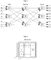
- Congestion can arise at any point in a multi-path network when data from more than one intermediate station converges on a single link for onward transmission. This style of communication is common in HPC and data center applications running on server clusters, it is also present when applications use network attached storage. In this latter context congestion also introduces another recognised issue, that of jitter in which the message delivery period becomes unpredictable. Congestion is an application performance killer; in a simple network delay and jitter prevent a system reaching peak performance levels. In complex networks, congestion can also necessitate the lengthier retransmission of data because intermediate stations between the endpoints simply discard or drop blocked traffic, reducing performance further. In practice, congestion spreads from the originating hot-spot until it backs up over the entire network resulting in un-associated routes being affected by a point of congestion in another part of the network. This is illustrated in the simple network diagram of Fig. 1 .
- Fig. 1 illustrates schematically a simplified conventional network.
- the rectangles on the left and right represent ingress and egress ports 2 respectively.
- the circles represent network crossbars 1 and the lines represent the interconnecting links, over which PDUs will traverse the network.
- each network crossbar 1 has only three input ports and three output ports 2.
- network crossbars have many more ports than this and this mechanism works equally well with higher arity crossbars.
- An example of a conventional network crossbar 1 is illustrated in Fig. 2 .
- Fig. 1 It can be seen In Fig. 1 that the total available bandwidth remains constant across the network; there being nine links available for transporting data at all stages across the network.
- the network of Fig. 1 has three stages of switching. Two stages of switching would be the minimum to complete a path from any ingress port to any egress port using the network crossbars 1. However this would result in poor performance for some traffic patterns. For example, if ingress port A was transmitting to egress port R while port B was sending to port S and port C was sending to port T then all three traffic flows would have to share a single link.
- Adaptive routing is effective if the traffic pattern is continually changing. Even if the initial adaptive guess is wrong, provided the network crossbars have a reasonable amount of buffering, the next adaptive choice of output is likely to be better. The continually changing output choice is going to provide new data to fill the under-utilised links and temporary output blocking can be held in the input buffers of the network crossbars until the network traffic pattern changes to allow it to proceed.
- Adaptive routing is less good at coping with a random set of communications that remain busy but unchanging for a long period.
- the initial guess is critical to the final total bandwidth of the network. If the initial guess is wrong then all the data could be serialized along only 3 of the 9 possible links delivering only 1/3 of the total network bandwidth. If the network has higher arity crossbars the problem can be much worse. If the crossbars have an arity of 64 then it can be as bad as only delivering 1/64 of the total network bandwidth. It is very common for network traffic patterns to be random in their connections but remain constant in the flow of data. For example a TCP/IP stream established between a client and server providing a full duplex data connection can have a very high bandwidth requirement that might be sustained for a long duration.
- the data stream is split into many separate PDUs, and these are sent one after another from the same ingress to egress ports of the network.
- Another example is an RDMA stream.
- a large block of data, perhaps hundreds of megabytes, is sent from one ingress port to another egress port again split into many separate PDUs.
- Congestion will get much worse as networks continue to become larger, faster and denser, with more connected end stations distributed over larger geographical areas. Removing congestion or at least minimising the effects of congestion allows full, sustained use of data center services enabling companies to operate more efficiently and cost effectively.
- congestion management techniques The problem with all congestion management techniques is that congestion has to be occurring before remedial action can be taken. Management at this point can benefit if the network traffic is of a single type and the data rate is constant and predictable, however the benefit is often reduced in the more complex environment of the data center where services run more diverse applications with dynamically changing data flows.
- congestion hot-spots appear rapidly and move around the network at an enormous rate. This increases the probability of over-constraining the wrong part of the network, as the point of congestion may have moved by the time notification and subsequent action have been applied.
- US20030058880 there is provided a multi-service queuing method and apparatus that provides exhaustive arbitration, load balancing, and support for rapid port failover.
- the fabric interface interfaces the switch fabric with the ingress and egress functions provided at a network node and provides virtual input and output queuing with backpressure feedback, redundancy for high availability applications, and packet segmentation and reassembly into variable length cells.
- Statistics regarding the virtual input and output queues are collected and packet queuing for the virtual input and output queues is controlled using the collected statistic to provide congestion control.
- US20050002334 discloses a method comprising: a) accepting a packet associated with a flow; b) generating a flow group identifier from the flow; c) determining whether any other packets associated with the flow group are present in a switch fabric; and d) if it is determined that other packets associated with the flow group are present in the switch fabric, then assigning the packet to a path being used by the flow group, and if it is determined that other packets associated with the flow group are not present in the switch fabric, then assigning the packet to a path using path congestion status information.
- the present invention seeks to overcome the problems encountered with conventional networks and in particular seeks to provide a method of minimising the effects of congestion in a multi-path network and of with improving the bandwidth of the network.
- the present invention provides a method of managing congestion in a multi-path network, the network having a plurality of network elements arranged in a plurality of switch stages and a plurality of network links interconnecting the network elements, the method defined by independent claim 1.
- the present invention provides, a multi-path network for use in a bridge, switch, router, hub or the like, the multi-path network defined by independent claim 7.
- the present invention provides an Ethernet bridge or router comprising a multi-path network as defined by independent claim 12. Preferred embodiments are defined by the dependent claims.
- Ethernet bridge or router introduces an additional protocol layer, referred to herein as an ' Encapsulation Layer ', that appears between the Physical Layer and the Data Link Layer of the standard OSI model which can encapsulate both Network Layer and Data Link Layer PDUs.
- an ' Encapsulation Layer ' that appears between the Physical Layer and the Data Link Layer of the standard OSI model which can encapsulate both Network Layer and Data Link Layer PDUs.
- an intermediate station is extended to include a station capable of forwarding packets encapsulated at the additional protocol layer referred to herein as the Encapsulation Layer.
- This type of station will be referred to herein as a Bridge Fabric or Network Fabric.
- a multi-port Bridge Fabric may be implemented by a collection of Bridge Fabric Switches (BFSs) interconnected by Bridge Fabric Switch Links (BFSLs).
- BFSs Bridge Fabric Switches
- BFSLs Bridge Fabric Switch Links
- a 'Fabric Protocol Data Unit' (FPDU)
- FPDU 'Fabric Protocol Data Unit
- CRC cyclic redundancy check
- a FPDU is used 10 in implementation of data transmission, acknowledgement and flow-control mechanisms.
- a FPDU can be further utilised to provide many other attractive features important to large, high performance, scalable Ethernet networks.
- the Ethernet bridge 1 is illustrated in Fig. 3 which may be connected to a plurality of separate Ethernet stations 2 and which implements the encapsulation of both Network Layer and Data Link Layer PDUs in a FPDU.
- the Ethernet bridge 1 generally comprises a multi-path network 10 in combination with a plurality of Ethernet ports 3 (only one is illustrated for the sake of clarity) with each port being individually connectable to an Ethernet station 2.
- the Ethernet ports 3 are generally conventional in design and each includes means for establishing a data connection with an Ethernet station, a receiving means or input 4 for performing Ethernet receive functions and a transmitting device or output 5 for performing Ethernet transmit functions.
- the Ethernet ports 3 are connected to a network interface 7 that provides conventional functionality such as packet buffering 6.
- the network interface 7 additionally includes an Ethernet PDU encapsulator 8 which connects the network interface 7 to ingress ports (not shown) of the network 10 and an Ethernet PDU decapsulator 9 which connects egress ports (not shown) of the network 10 back to the Ethernet ports 3.
- the Ethernet PDU encapsulator 8 implements the protocol of the Encapsulation Layer and thus is responsible for the generation of the FPDUs.
- each port 3 of the Ethernet bridge 1 has a respective network interface 7 and thus a respective Ethernet PDU encapsulator 8 and a respective Ethernet PDU decapsulator 9.
- the network 10 which is a proprietary multi-path network such as the one shown in Fig. 5 , comprises a plurality of interconnected network elements 18 referred to herein as bridge fabric switches (BFSs) interconnected by network links 17 in the form of bridge fabric switch links (BFSLs).
- Each BFSL 17 is preferably a bi-directional (full duplex) connection. Data is sent in each direction and acknowledgments and flow control state for data in one direction can be multiplexed with the data sent in the opposite direction of the BFSL.
- Fig. 4 illustrates a BFSL 17 in combination with the input and output connections to the link 17.
- FPDU Fabric Protocol Data Unit
- the present invention can be applied to any network where there are multiple routes from a source or ingress port to a destination or egress ports. All the examples given below show unidirectional links to improve the clarity of the diagrams but the mechanism is equally valid for a full duplex link implementation.
- the present invention is based on the idea of actively and continually monitoring the levels of both congestion and under-utilization within the network and, when necessary, re-routing some of the traffic flows across other parts of the network in order to better load balance the network as a whole, thereby increasing network utilisation.
- the implementation of the present invention is a three step process, namely:
- the invention relies upon the communication of small amounts of control information between individual BFSs in the network.
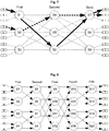
- Fig. 5 illustrates a simple example of a traffic flow that is suffering congestion.
- ingress port A is sending to egress port R and ingress port D is sending to port S.
- the illustrated multi-path network is assumed to be a 10Gbe Ethernet bridge in which the bandwidth of the network ports matches the bandwidth of the BFSs and the BFSLs.
- a single port sending data at 100% of its rate requires 100% of the capacity of the BFSs and the BFSLs to avoid congestion.
- BFS S4 which is the Congesting Switch (CS) while trying to send data to BFS S7.
- CS Congesting Switch
- BFS S4 Only BFS S4 is able to detect the congestion. Congestion cannot be reasoned at BFS S7 because the two streams of interleaving FPDUs entering BFS S7 would have the same pattern if ingress ports A and D were only trying to send data at 50% their maximum rate and in that case there would be no congestion.
- CS S4 is receiving data at the full (100%) rate on two input links and so must buffer this data to prevent it being lost. Congestion then occurs once the BFS input data buffers are being filled faster than they are being emptied.
- RS S7 Independently of the congestion at BFS S4, RS S7 is able to recognise that only one of its input links is receiving data. It can also measure to what, if any, extent its other two input links are being used. In the illustrated example the other two links of RS S7 are not being used at all.
- Fig. 6 and Fig. 7 show two solutions that correct the congestion problem shown in Fig. 5 . Both solutions require a different link to be used between the first and second stages of switching.
- the congestion is removed by changing the network route of the data stream from ingress port D to egress port S.
- BFS S2 which becomes the Adapting Switch (AS)
- AS Adapting Switch
- Fig. 7 the congestion is removed by changing the network route of the data stream from ingress port A to egress port R.
- BFS S1 which is the Adapting Switch as it starts to send data to BFS S6, instead of to the CS S4.
- congestion control information is communicated in the form of tags that are added to the headers of FPDUs moving through the network.
- an FPDU is used to carry a tag that indicates that the previous BFS, i.e. the BFS the FPDU has just left, is congested.
- a reverse acknowledgement control flow is also provided in the form of a small amount of control information that is used to indicate the successful transmission of the bulk data in the forward direction.
- This control information could be provided through the use of additional sideband signals or could be implemented by stealing a small amount of bandwidth from the reverse direction on a full duplex link.
- the reverse acknowledgement control flow performs two useful functions. Firstly it signals the delivery of data packets to their destinations. This is used to provide control of packet ordering in an otherwise dynamic routing multi-path network. If a data flow has to be changed to relieve congestion, then new FPDUs are not released onto the link of the new route until all the acknowledgments relating to data transmitted over the old route have been received at the point in the network where the route change is going to take place. Secondly the use of reverse acknowledgements provides a means for communicating re-routing information back to earlier stages in the network to enable a data flow to be redirected onto less congested links.
- the previous example of Figs. 5, 6 and 7 illustrated a network with two levels of destination switching and one adaptive switching.
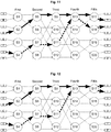
- FIG. 8 illustrates an example of a multi-path network with 3 levels of destination switching (BFS S9 to S20) and 2 levels of adaptive switching (BFS S1 to S8). The arity of these switches has been reduced to simplify the example.
- Fig. 8 it can be seen that the illustrated network is symmetrical. Symmetry is not a requirement of the present invention but can simplify identification of the Adapting Switch required to remedy a congestion situation using the congestion management method of the present invention.
- Fig. 9 the multi-path network of Fig. 8 is shown with two connections attempting to utilise the same network link and thus congesting the link: the first connection is from ingress port D to egress port T and the second connection is from ingress port G to egress port U.
- the congestion is occurring between the third and fourth stages of network switching and in this case BFS S9 will detect congestion and become the CS whilst and BFS S13 will look for other uncongested links and become the RS.
- BFS S9 will detect congestion and become the CS whilst and BFS S13 will look for other uncongested links and become the RS.
- BFS S9 will detect congestion and become the CS whilst and BFS S13 will look for other uncongested links and become the RS.
- the network of Fig. 8 it is relatively easy to identify an uncongested link as the BFS has only two input ports so the link to the other of the two input ports must automatically be identified as the uncongested link.
- real networks will
- Figs. 10 and 11 show that to address the congestion problem of Fig. 9 a change must be made either on BFS S5 to change the D to T flow or on BFS S7 to change the G to U flow.
- the former solution is shown in Fig. 10 and the latter in Fig. 11 .
- the network is symmetric, and with the congestion arising between the third and fourth stages of the network, so the re-routing must occur between the second and third stages i.e. the AS is in the symmetrically equivalent stage of the network as the RS.
- Fig. 12 two different connections across the multi-path network are illustrated, this time creating congestion between the fourth and fifth switching stages.
- the RS located at the fifth stage of the network, so an appropriate AS is to be found in the first stage of the network.
- selecting an alternative network link for the first connection at BFS S2 results in a new route across the network which avoids the link between BFSs S13 and S17, as shown in Fig. 13 .
- selecting an alternative network link for the second connection at BFS S4 similarly results in a new route across the network for the connection between port G and port S which avoids the link between BFSs S13 and S17.
- Fig. 15 gives a final, more complex example of a traffic flow where both streams are routed over two links.
- the preferred route correction would correct for congestion at BFS S17.
- the congestion is only detected by BFS S9 i.e. the CS is BFS S9.
- full correction of the congestion requires two separate correction operations.
- the first correction operation identifies BFS S13 as the RS and the solutions to the congestion correspond to the solutions illustrated in Figs. 10 and 11 .
- This rerouting of the data packets would generate a new, still congested traffic pattern corresponding to the congestion illustrated in Fig. 12 with BFS S17 as the RS.
- This second tranche of congestion may then be corrected using similar solutions to those illustrated in Figs. 13 and 14
- the above examples show that a simple algorithmic approach can be used to identify the AS where a change has to occur to correct a congestion problem. Where the network has symmetry and the congestion correction requires the data packets to come in on a different link on the switching stage closest to the egress ports then the change must be made on the switching stage closest to the ingress ports.
- the networks illustrated in the figures have BFSs with two input ports and two output ports. It may also be seen that if a data stream comes in on the top input port of a fifth network stage BFS then it left the top output port of a first network stage BFS. Likewise, if the data stream comes in on the top input port of a fourth stage BFS then it left the top port of a second switching stage BFS. Provided a similar symmetry exists in a network that has BFSs with a much higher arity, then consistent numbering of the BFS ports allows the RS to identify easily the correct output port the AS should use to make the data packets arrive on an uncongested link into the RS.
- each BFS may include a map of the network which would enable identification of an alternative route across the network to the alternative uncongested BFSL of the RS.
- the multi-path network described herein preserves packet ordering whilst providing dynamic routing, and ideally adaptive routing, of FPDUs across the network through the use of acknowledgements.
- bandwidth usage can be significantly increased. That is to say, release of the FPDU acknowledgement is not delayed until after the entire payload of the FPDU is received.
- the acknowledgement is already in transit back to the ingress port of the FPDU. If the FPDU is big enough and the network delivery time is low enough, then the acknowledgement will be received at the ingress port before the ingress port has finished transmitting the whole of the FPDU.
- the next FPDU can then be sent and adaptively routed without any possibility of it being received before the first and without any possibility of it being duplicated because no network reconfiguration is required to maintain a single route.
- This same packet ordering technique is also employed to maintain packet order when, as a result of congestion, a series of data packets is interrupted and the latter data packets rerouted.
- each BFSL of the network is assigned a plurality of "flow channels" to support one or more source to destination connections simultaneously (where the source is defined as an ingress point to the network, and the destination is defined as an egress point (or points) from the network). Having many flow channels increases the amount of time a channel can be held open without having to wait for the acknowledgment to be returned.
- the full network source to destination flow of a FPDU uses a series of single flow channels each allocated in turn on each BFSL the FPDU visits as it crosses the network. Whilst the particular flow channel used by an FPDU might differ for each individual BFSL visited, during transit of the FPDU across the network, each flow channel entry on a BFSL has enough state to map the corresponding flow channel of the previous BFSL the FPDU used to arrive at the current flow channel entry. As a result the network, as a whole, records the path of the FPDU as it crosses the network from source to destination.
- Fig. 4 illustrates a BFSL 17, between two interconnected BFSs 18, providing a flow channel that is part of a data stream from a network ingress port to a network egress port.
- Fig. 4 only the FPDU channel 17 is shown although the acknowledgements 14 are illustrated within the BFSs 18.
- Each flow channel is mapped onto a BFSL 17 and each BFS at each end of the BFSL 17 includes a first state table 11 in the form of an output flow channel table (OFCT) and a second state table 12 in the form of an input flow channel table (IFCT) in which entries specific to each flow channel of the BFSL 17 are recorded and stored until over-written.
- Each location in the OFCT 11 has an associated location in the IFCT 12 in the form of a directly corresponding location in the IFCT 12.
- OFCT entry 3 corresponds to IFCT entry 3.
- some of the IFCT state is a copy of the OFCT state and some of the OFCT state is a copy of the IFCT state.
- output data 13 is multiplexed with acknowledgment values 16 relating to FPDUs transmitted in the opposite direction to create the BFSL data stream and at the next BFS 18 the input data 15 to the BFS 18 is separated from acknowledgments 16 concerning FPDUs transmitted in the other direction.
- FPDUs received from a BFSL are buffered in one of a plurality of buffering devices 21, preferably FIFOs, (only one is shown in the figures for the sake of clarity) while they wait to make a connection to a data crossbar switch which forms part of each BFS 18.
- the flow channel number of the received acknowledgments 16 is used to index the OFCT 11 to retrieve the mapping of the previous BFSL and this is appended to form a routable acknowledgment 14 that is sent to an acknowledgment crossbar switch.
- a "source to destination" connection is dynamically established across the whole network as a first FPDU travels across the network and then remains exclusively allocated to subsequent FPDUs having the same ordering requirement whilst any preceding FPDUs with the same ordering requirements remains in transit.
- the ordering requirements may be, but are not limited to the following: a source to destination address, with or without a level of priority; a message class; VLANS; higher level protocol requirements; IP numbers; or quality of service.
- This is achieved by storing in the OFCT 11 a destination address value and state which describes the upstream path, back towards the source ingress port, for the most recent FPDU transmitted by a flow channel of the BFSL 17.
- a plurality of destination address values and states for a plurality of FPDUs are stored each destination address value and state being stored in association with a respective flow channel of the BFSL.
- the basic methodology for transmitting an FPDU on one or more BFSLs of a plurality of BFSLs of a network fabric is as follows.
- the header data of the new FPDU is checked to see if the FPDU's ordering requirements match any of the valid channels of that BFSL.
- This match is executed by performing a parallel compare of all the entries in the OFCT 11.
- Each compare is an equality test between the ordering requirement in the header of the FPDU and the ordering requirement stored in the OFCT 11.
- Each compare also requires an equality test of the source port and source flow channel the FPDU has come from.
- an empty/unused channel is allocated and the input port of the BFS, the flow channel of the BFSL and ordering requirement data of the FPDU are stored in relation to the allocated channel in the OFCT 11.
- the empty/unused channel may be allocated by the BFS randomly or quasi-randomly or may be allocated using one or more predefined rules. If a match does exist, then the FPDU is allocated the same flow channel that most recently carried a previous FPDU with matching ordering requirement data. The state of the allocated channel is then updated in the OFCT 11 with information representative of the new FPDU (which is described in greater detail below).
- Each BFS 18 has a data crossbar switch that is used to transport data from an input BFSL 17 to an output BFSL 17.
- Each BFS 18 also has an acknowledgment crossbar switch, in parallel with the data crossbar switch, which is used to return BFSL acknowledgment tokens back from a network egress port to the network ingress port.
- the OFCT 11 holds for each flow channel the return address for the most recently transmitted FPDU. This return address is in two parts: it has the port number the FPDU came from and also the flow channel assigned on the previous BFSL.
- the return address is used for the acknowledgement token of that FPDU to direct the acknowledgment from the BFS data output port through the acknowledgment crossbar switch into the IFCT 12 where it can be directed as a new acknowledgement token back to the next BFS in the acknowledgement's return path towards the ingress port for that FPDU.
- Each flow channel is assigned a count value representative of the number of units of data transmitted which is referred to herein as the Data Flow Count (DFC).
- the DFC value is incremented by the size of the FPDU being transmitted.
- the count value of each of the flow channels is held at both ends of the BFSL 17.
- the DFC has a master value at the sending end of the BFSL and a slave (copy) value at the receiving end.
- the master DFC value is held in the OFCT 11 and the slave DFC value is held in the IFCT 12.
- Each flow channel is also assigned a count value representative of the number of acknowledged units of data which is referred to herein as the Acknowledgement Flow Count (AFC).
- AFC Acknowledgement Flow Count
- the AFC master value is held in the IFCT 12 and the AFC slave value is held in the OFCT 11.
- the DFC reaches a predetermined maximum value it simply wraps back through zero. Overflow on the DFC is acceptable as it is only ever compared against the AFC that will also wrap back through zero in the same way as it is assigned the same predetermined maximum value.
- the unit measure of data is set as a predetermined number of bytes. This unit measure is set small enough to give reasonable resolution but big enough to minimise state and overhead on the size of headers in the FPDUs and the size of the acknowledgements returned. In one embodiment it is envisaged that the count values correspond to a count of whole FPDUs, instead of the total data size held in the FPDUs. This gives the same understanding of FPDU ordering but removes the knowledge of total data against the flow channel.
- the number of units of data being sent in the FPDU is calculated from the size field in the FPDU header.
- the master DFC value stored in the OFCT 11 in relation to the flow channel allocated to that FPDU is then incremented by the number of units of data being sent in the FPDU.
- the new DFC value is inserted into the header of the FPDU for transmission on the BFSL 17.
- a similar rolling count value is established in relation to the returning acknowledgement which is described in greater detail below.
- the channel count value is calculated by taking the difference between the two rolling count values that are part of the state of the flow channel.
- all the DFC and AFC stored in the OFCT 11 and the IFCT 12 are initialised to the same value making the difference between the rolling count values equal to zero. Once initialised the DFC and AFC values are then only changed by the passing FPDU data and acknowledgments using the BFSL.
- an acknowledgement is immediately returned. As mentioned earlier, issuance of the acknowledgement is not delayed pending receipt of the entire payload of the FPDU.
- the acknowledgement is automatically routed back to the original ingress port following in reverse the path taken by the FPDU in the forward direction. This is done using the input port number and input flow channel number stored in each of the OFCTs 11.
- the acknowledgement includes information taken from the header of the FPDU that generated the acknowledgement on the unit size value of the FPDU.
- the second rolling master AFC value, stored in the IFCT 12 is adjusted by the size value held in the returning acknowledgement.
- this master AFC value is included in the acknowledgment token returned on the BFSL 17 and is loaded into the slave AFC value held in the OFCT 11.
- the difference between the two rolling counts indicates the total amount of unacknowledged data.
- the values can be compared in either the OFCT 11 or the IFCT 12. It should be noted that, due to the transmission delay along a BFSL the DFC value is updated in the OFCT 11 before it is copied into the IFCT 12 and likewise the AFC is updated in the IFCT 12 before it is copied into the OFCT 11. This has the effect of making the comparison of the Master DFC value and the Slave AFC in the OFCT 11 appear to be different for longer than the comparison of the Slave DFC value and the Master AFC value in the IFCT 12.
- the new FPDU must be routed along the same path, using the same flow channel, as the previous FPDU for this source/destination. This is done by using the destination port number or other number with ordering requirements stored in the IFCT 12 which was loaded the first time a connection was made on the data crossbar for an FPDU having the same ordering requirements.
- congestion on a BFSL must be identified.
- the depth of the data waiting in the buffers 21 of the BFSs is monitored and used as a simple measure of congestion. The more congested an output port is the deeper the depth of the queue the data is being delivered from. Hence, detecting more than a fixed buffer depth is a good enough measure for marking a FPDU (and the BFSL it requires) as being congested.
- alternative conventional techniques may be employed to detect congestion on the BFSLs but for the purposes of the following discussion, it is assume that link congestion is detected through monitoring the queue depth of the buffers.
- the next FPDU being transmitted on the congested link has a tag added to the header of the FPDU indicating that the FPDU is being transmitted on a congested network link.
- the tag is extracted from the FPDU header.
- This control token instructs the AS to halt the forward transmission of all further data packets intended for a particular destination until further notice.
- the first return control token follows the same path in reverse that the FPDU followed to reach the RS. This means that the AS will ultimately receive the first return control token on the same flow channel for which further data packet transmission is to be suspended.
- the RS then continues to function normally transmitting forward data packets that are received on whichever flow channels are assigned to the data packets. Ultimately, however, no new data packets will be received for the data stream that has been suspended and shortly thereafter the DFC and the AFC for that flow channel will match confirming that acknowledgements have been received for all the data packets transmitted on that flow channel.
- the RS identifies the least recently used BFSL connected to an input port of the RS as an alternative uncongested link.
- Selection of an uncongested link can be performed by counting the idle cycles of a network link over a period of time.
- a simple implementation that provides a rolling uncongested value is shown in Fig. 16 .
- the delay of the idle count through the delaying buffer should be a few times larger than the time it takes to transmit a FPDU.
- Each input link to a BFS is provided with this mechanism to measure the lack of congestion. Another mechanism is then required to find the network link with the largest uncongested value and this is communicated to all the links that are connected to the BFS. The link with the largest uncongested value becomes the best candidate for accepting a new redirected data stream.
- the RS performs this check when it first receives an FPDU with a congestion tag so as to verify an input link with a sufficiently large enough uncongested value exists to make it worth sending a token to the relevant AS. The check is then repeated once the DFC and the AFC are equal to identify the alternative link from the AS which is in communication with the uncongested link of the RS.
- the RS Once the RS has identified the alternative link from the AS on which future data packets are to be transmitted, this is communicated back, like the suspension token, to the AS using the last acknowledgement.
- the alternative link or best link token follows the same path in reverse back to the AS.
- the AS receives the best link token and the DFC and the AFC are equal, it is then free to re-start the forward transmission of the suspended data packets but on the alternative link identified by the RS.
- the AS receives the best link token and the DFC and the AFC are equal, it is then free to re-start the forward transmission of the suspended data packets but on the alternative link identified by the RS.
- a further important feature of the congestion management method described herein is the timing of when rerouting of data streams occurs.
- An effective implementation of dynamic rerouting relies on a good decision as to when it is appropriate to change a data stream. In some respects it is more important to know when not to change rather than when a change should be made.
- a feedback mechanism is employed to improve the total throughput of the network.
- the rate of adjustments must be limited to allow a change to take place before another change is attempted.
- the delay before another adjustment is attempted must be at least equal to the time it takes for a congested data stream to be fully redirected. This delay is signalled on both the link the congestion is being removed from (to prevent another stream being removed before the first has gone) and the delay must be signalled on the link the data stream is being rerouted onto (to prevent the lack of congestion on that link being accounted for twice).
- the multi-path network includes a mechanism that indicates the age of PDUs from ingress into the network, if there is a choice of congested PDUs arriving from a network link, then it is preferred to redirect an older data stream. This can be done by finding an average age of all PDUs arriving at a BFS and only allowing PDUs that are older than the average to be rerouted.
- the present invention described above can dramatically improve the total bandwidth of any traffic pattern, particularly unchanging random connections which static routing completely fails to deliver any performance. It is especially good at removing the very badly congested connections that often become the critical path for larger applications using the network. Also, it is very responsive to any changes in the network traffic pattern, whilst being unaffected if some of the network traffic is continually changing. It can optimally adjust a network with tens of thousands of ports in just a few tens of microseconds.
- the multi-path network described herein is truly scalable offering from 256 ports or fewer up to 48,000 ports or more.
- a single Ethernet bridge or router using the method and apparatus described herein is capable of providing greatly increased connectivity in comparison to conventional Ethernet bridges. For example, currently the largest 10Gbe Ethernet bridges (which are modular in construction) offer only 288 ports. With the network of the present invention, a single Ethernet bridge is possible which is capable of operating at 10Gbe or above and is capable of offering, for example, 48,000 ports.
- the present invention may be applied to any multi-path network which transports data packets between inputs and outputs to the network.
- the multi-path network has been described with respect to full duplex links, the links may alternatively comprise a half duplex link with a sideband to allow acknowledgments tokens and tags to be transmitted in the opposing direction.
- the present invention has been described with respect to a specific multi-path network, it will, of course, be apparent that the present invention is applicable to any multi-path network which implements dynamic routing, such as adaptive routing. Moreover, the present invention is equally applicable to network topologies other than those illustrated herein involving different numbers of network elements and different degrees and different arrangements of interconnection. Also the present invention is not restricted to a network fabric which uses encapsulation of the data packets during its transit across the network.
- buffers comprising FIFOs it is to be understood that other forms of buffering may be employed which are capable of storing in an ordered manner a plurality of separate data packets.
Claims (12)
- Procédé de gestion de l'encombrement lors de la transmission d'un flux de paquets de données à travers un réseau à trajets multiples (10) ayant une pluralité d'éléments de réseau (18) disposés en une pluralité d'étages de commutation, et ayant une pluralité de liaisons de réseau (17) interconnectant les éléments de réseau, le procédé comprenant les étapes consistant à :détecter un encombrement sur une liaison de réseau de la pluralité de liaisons de réseau interconnectant un port de sortie d'un premier élément de réseau de la pluralité d'éléments de réseau avec un premier port d'entrée d'un deuxième élément de réseau de la pluralité d'éléments de réseau, le premier élément de réseau étant dans un premier étage de commutation de la pluralité d'étages de commutation et le deuxième élément de réseau étant dans un étage de commutation ultérieur de la pluralité d'étages de commutation ;communiquer la détection de l'encombrement du premier élément de réseau au deuxième élément de réseau en attachant une étiquette d'encombrement à l'en-tête d'un paquet de données ultérieur destiné à être transmis au deuxième élément de réseau sur la liaison de réseau encombrée ; en réponse à la réception dudit paquet de données ultérieur par ledit deuxième élément de réseau, l'identification d'une liaison de réseau non encombrée de la pluralité de liaisons de réseau connectée à un deuxième port d'entrée dudit deuxième élément de réseau ; etdéterminer une nouvelle route à travers le réseau à trajets multiples qui comporte la liaison de réseau non encombrée identifiée et diriger de futurs paquets de données dans le flux de paquets de données le long de la nouvelle route.
- Procédé selon la revendication 1, chaque élément de réseau de la pluralité d'éléments de réseau ayant une pluralité de ports d'entrée et au moins un tampon de paquets de données (21) étant associé à chaque port d'entrée, l'étape de détection de l'encombrement comportant le contrôle du contenu des tampons de paquets de données du premier élément de réseau, moyennant quoi un encombrement est détecté lorsque le contenu d'un tampon de paquets de données dépasse un seuil prédéterminé.
- Procédé selon la revendication 2, le contenu des tampons de paquets de données étant contrôlé en contrôlant la profondeur des tampons et, lorsque le contenu d'un tampon de paquets de données dépasse le seuil prédéterminé, la liaison de réseau encombrée étant la liaison de réseau sur laquelle le paquet ultérieur de données à sortir de ce tampon de paquets de données est destiné à être transmis.
- Procédé selon la revendication 1, comprenant en outre, en réponse à la réception par le deuxième élément de réseau d'un ou plusieurs paquets de données ayant chacun une étiquette d'encombrement dans son en-tête, l'étape de sélection d'un paquet de données ayant une étiquette d'encombrement dans son en-tête et de d'émission à destination d'un troisième élément de réseau dans un étage de commutation précédant l'étage de commutation du premier élément de réseau d'un premier jeton de commande pour empêcher la transmission par le troisième élément de réseau d'autres paquets de données ayant la même exigence de classement que le paquet de données choisi par le deuxième élément de réseau.
- Procédé selon la revendication 3, dans lequel, lorsqu'une pluralité de paquets de données présentant des étiquettes d'encombrement dans leurs en-têtes et des exigences de classement différentes sont reçues par le deuxième élément de réseau, le plus ancien de la pluralité de paquets de données présentant des étiquettes d'encombrement dans leurs en-têtes étant choisi et à la réception du premier jeton de commande, le troisième élément de réseau empêche la transmission d'autres paquets de données ayant la même exigence de classement que le paquet de données choisi, et éventuellement, en réponse à la réception par le troisième élément de réseau d'un premier jeton de commande, le procédé comprenant en outre les étapes consistant à l'arrêt par un troisième élément de réseau de la transmission de paquets de données ayant la même exigence de classement que le paquet de données choisi par le deuxième élément de réseau ; et à l'attente d'instructions, par le troisième élément de réseau, concernant le réacheminement des paquets de données arrêtés.
- Procédé selon la revendication 1, comprenant en outre l'étape consistant à contrôler l'activité des liaisons de réseau connectées aux ports d'entrée des éléments de réseau, moyennant quoi l'étape consistant à identifier une liaison de réseau non encombrée comprend l'identification de la liaison de réseau la moins active connectée à un port d'entrée du deuxième élément de réseau,
ou chaque liaison de réseau étant partagée par une pluralité de canaux de liaison pouvant être choisis individuellement et un canal de liaison de chaque liaison de réseau sur le trajet d'un premier paquet de données transmis sur le réseau étant attribué individuellement exclusivement à des paquets de données ultérieurs ayant la même exigence de classement que ledit premier paquet de données jusqu'à ce qu'un accusé de réception du paquet de données précédent le plus récent ayant la même exigence de classement soit retransmis par une liaison exclusivement attribuée et, éventuellement, le réseau à trajets multiples comportant une pluralité de ports de sortie et un accusé de réception de livraison étant émis par un port de sortie lorsqu'un paquet de données est reçu au port de sortie, l'accusé de réception de livraison étant transmis sur le réseau en suivant en sens inverse le trajet emprunté par le paquet de données faisant l'objet d'un accusé de réception, et l'état de chaque canal de liaison dans le trajet emprunté par le paquet de données faisant l'objet de l'accusé de réception étant mis à jour par l'accusé de réception,
ou lorsque le réseau à trajets multiples comporte au moins un degré de symétrie, les futurs paquets de données étant réacheminés par un élément de réseau dans un étage de commutation symétrique avec l'étage de commutation du deuxième élément de réseau et éventuellement, la liaison de réseau choisie pour la transmission des paquets de données réacheminés étant symétrique avec la liaison de réseau non encombrée du deuxième élément de réseau. - Réseau à trajets multiples (10) destiné à être utilisé dans un pont, un commutateur, un routeur ou un concentrateur, le réseau à trajets multiples comprenant une pluralité de ports réseau ; une pluralité d'éléments de réseau (18) disposés en une pluralité d'étages de commutation ; et une pluralité de liaisons de réseau (17) interconnectant les éléments de réseau et les ports de réseau pour transporter un flux de paquets de données sur le réseau à trajets multiples, chaque élément de réseau ayant :
au moins un détecteur d'encombrement pour détecter l'encombrement sur une liaison de réseau de la pluralité de liaisons de réseau connectée entre un port de sortie d'un premier élément de réseau de la pluralité d'éléments de réseau à un premier étage de commutation de la pluralité d'étages de commutation et un premier port d'entrée d'un deuxième élément de réseau de la pluralité d'éléments de réseau à un deuxième étage de commutation de la pluralité d'étages de commutation, le détecteur d'encombrement du premier élément de réseau étant apte à communiquer la détection d'encombrement au deuxième élément de réseau en attachant une étiquette d'encombrement à l'en-tête d'un paquet ultérieur de données destiné à être transmis au deuxième élément de réseau sur la liaison de réseau encombrée à destination du deuxième élément de réseau ; et au moins un moniteur d'activité de liaison pour identifier une liaison de réseau non encombrée de la pluralité de liaisons de réseau connectée à un autre port d'entrée du deuxième élément de réseau au deuxième étage, et les éléments de réseau étant aptes à transporter des paquets de données ultérieurs dans le flux de paquets de données à l'aide de la liaison de réseau non encombrée. - Réseau à trajets multiples selon la revendication 7, chaque élément de réseau de la pluralité d'éléments de réseau ayant une pluralité de ports d'entrée et chaque port d'entrée étant associé à au moins un tampon de paquets de données (21), le détecteur d'encombrement étant apte à contrôler le contenu des tampons de paquets de données, moyennant quoi un encombrement est détecté lorsque le contenu d'un tampon de paquets de données dépasse un seuil prédéterminé et, éventuellement, le détecteur d'encombrement étant apte à contrôler la profondeur des tampons.
- Réseau à trajets multiples selon la revendication 7, dans lequel, en réponse à la réception par un élément de réseau d'un paquet de données présentant une étiquette d'encombrement dans son en-tête, chaque élément de réseau est apte à émettre, à destination d'un troisième élément de réseau dans un étage de commutation de la pluralité d'étages de commutation précédant l'étage de commutation du premier élément de réseau qui a détecté l'encombrement, un premier jeton de commande pour empêcher la transmission par le troisième élément de réseau d'autres paquets de données ayant la même exigence de classement que le paquet de données reçu par le deuxième élément de réseau et éventuellement, en réponse à la réception par un élément de réseau d'un premier jeton de commande, chaque élément de réseau étant apte à arrêter la transmission de paquets de données ayant la même exigence de classement que le paquet de données reçu par le deuxième élément de réseau qui comportait une étiquette d'encombrement dans son en-tête et à attendre des instructions concernant le réacheminement des paquets de données arrêtés.
- Réseau à trajets multiples selon la revendication 7, le moniteur d'activité de liaison étant apte à identifier une liaison de réseau non encombrée après qu'un paquet de données ayant une étiquette d'encombrement dans son en-tête a été reçu par le deuxième élément de réseau, et le moniteur d'activité de liaison étant éventuellement apte à identifier une liaison de réseau non encombrée uniquement après que le deuxième élément de réseau a reçu des accusés de réception pour tous les paquets de données ayant la même exigence de classement que le paquet de données ayant une étiquette d'encombrement dans son en-tête et éventuellement, l'élément de réseau étant apte à émettre une instruction de réacheminement à destination du troisième élément de réseau comportant des informations sur la liaison de réseau non encombrée qui a été identifiée par le moniteur d'activité de liaison une fois que tous les accusés de réception de livraison pour tous les paquets de données ayant la même exigence de classement ont été reçus par le deuxième élément de réseau.
- Réseau à trajets multiples selon la revendication 7, comportant en outre une pluralité de ports de sortie, les ports de sortie étant aptes à émettre un accusé de réception de livraison lorsqu'un paquet de données est reçu et les éléments de réseau étant aptes à transmettre l'accusé de réception de livraison sur le réseau en suivant en sens inverse le trajet emprunté par le paquet de données faisant l'objet d'un accusé de réception,
ou le réseau à trajets multiples comportant au moins un degré de symétrie et les paquets de données étant réacheminés par un élément de réseau dans un étage de commutation symétrique avec l'étage de commutation de l'élément de réseau qui reçoit l'étiquette d'encombrement et éventuellement, la liaison de réseau choisie pour la transmission des paquets de données réacheminés étant symétrique avec la liaison de réseau non encombrée de l'élément de réseau qui reçoit l'étiquette d'encombrement,
ou chacune de la pluralité des liaisons de réseau étant une liaison duplex permettant à des signaux d'être transmis simultanément dans des directions opposées. - Pont ou routeur Ethernet (1) comprenant :un réseau à trajets multiples (10), le réseau à trajets multiples comprenant une pluralité de ports réseau ; une pluralité d'éléments de réseau (18) disposés en une pluralité d'étages de commutation ; et une pluralité de liaisons de réseau (17) interconnectant les éléments de réseau et les ports de réseau pour transporter un flux de paquets de données à travers le réseau à trajets multiples ;chaque élément de réseau de la pluralité d'éléments de réseau ayant au moins un détecteur d'encombrement pour détecter l'encombrement sur une liaison de réseau de la pluralité de liaisons de réseau connectées à un de ses ports de sortie, un détecteur d'encombrement d'un premier élément de réseau à un premier étage de commutation de la pluralité d'étages de commutation étant configuré pour détecter l'encombrement à un de ses ports de sortie qui est connecté à un premier port d'entrée d'un deuxième élément de réseau de la pluralité d'éléments de réseau à un deuxième étage de commutation de la pluralité d'étages de commutation, le détecteur d'encombrement du premier élément de réseau étant en outre apte à communiquer la détection d'encombrement à un troisième élément de réseau de la pluralité d'éléments de réseau ; etau moins un moniteur d'activité de liaison pour identifier une liaison de réseau non encombrée de la pluralité de liaisons de réseau connectée à un autre port d'entrée du deuxième élément de réseau au deuxième étage de commutation, et la pluralité d'éléments de réseau étant apte à amener le troisième élément de réseau à coordonner le transport de paquets de données ultérieurs dans le flux de paquets de données à l'aide de la liaison de réseau non encombrée, ce qui permet au deuxième élément de réseau d'identifier la liaison de réseau non encombrée, et éventuellement, le détecteur d'encombrement du premier élément de réseau communiquant la détection d'encombrement au deuxième élément de réseau en attachant une étiquette d'encombrement à l'en-tête d'un paquet de données suivant dans le flux de paquets de données destinés à être transmis au deuxième élément de réseau sur la liaison de réseau encombrée.
Applications Claiming Priority (3)
| Application Number | Priority Date | Filing Date | Title |
|---|---|---|---|
| GB0811813.5A GB2461132B (en) | 2008-06-27 | 2008-06-27 | Method of data delivery across a network |
| EP09769561.3A EP2316202B1 (fr) | 2008-06-27 | 2009-06-23 | Procédé de distribution de données sur un réseau |
| PCT/GB2009/001574 WO2009156720A1 (fr) | 2008-06-27 | 2009-06-23 | Procédé de distribution de données sur un réseau |
Related Parent Applications (1)
| Application Number | Title | Priority Date | Filing Date |
|---|---|---|---|
| EP09769561.3A Division EP2316202B1 (fr) | 2008-06-27 | 2009-06-23 | Procédé de distribution de données sur un réseau |
Publications (2)
| Publication Number | Publication Date |
|---|---|
| EP3484108A1 EP3484108A1 (fr) | 2019-05-15 |
| EP3484108B1 true EP3484108B1 (fr) | 2020-09-09 |
Family
ID=39683276
Family Applications (2)
| Application Number | Title | Priority Date | Filing Date |
|---|---|---|---|
| EP09769561.3A Active EP2316202B1 (fr) | 2008-06-27 | 2009-06-23 | Procédé de distribution de données sur un réseau |
| EP18188902.3A Active EP3484108B1 (fr) | 2008-06-27 | 2009-06-23 | Procédé de distribution de données sur un réseau |
Family Applications Before (1)
| Application Number | Title | Priority Date | Filing Date |
|---|---|---|---|
| EP09769561.3A Active EP2316202B1 (fr) | 2008-06-27 | 2009-06-23 | Procédé de distribution de données sur un réseau |
Country Status (5)
| Country | Link |
|---|---|
| US (2) | US8908529B2 (fr) |
| EP (2) | EP2316202B1 (fr) |
| CN (1) | CN102084627B (fr) |
| GB (1) | GB2461132B (fr) |
| WO (1) | WO2009156720A1 (fr) |
Families Citing this family (26)
| Publication number | Priority date | Publication date | Assignee | Title |
|---|---|---|---|---|
| GB2461132B (en) * | 2008-06-27 | 2013-02-13 | Gnodal Ltd | Method of data delivery across a network |
| GB2467424A (en) * | 2009-01-28 | 2010-08-04 | Ibm | Managing overload in an Ethernet network by re-routing data flows |
| US20110283014A1 (en) * | 2010-05-14 | 2011-11-17 | Rahul Malik | Distribution of Multimedia Content over a Network |
| US9565132B2 (en) * | 2011-12-27 | 2017-02-07 | Intel Corporation | Multi-protocol I/O interconnect including a switching fabric |
| US9350665B2 (en) * | 2012-08-31 | 2016-05-24 | Cisco Technology, Inc. | Congestion mitigation and avoidance |
| US8995277B2 (en) * | 2012-10-30 | 2015-03-31 | Telefonaktiebolaget L M Ericsson (Publ) | Method for dynamic load balancing of network flows on LAG interfaces |
| US8989017B2 (en) * | 2012-12-14 | 2015-03-24 | Intel Corporation | Network congestion management by packet circulation |
| US9118984B2 (en) | 2013-03-15 | 2015-08-25 | International Business Machines Corporation | Control plane for integrated switch wavelength division multiplexing |
| US9609086B2 (en) | 2013-03-15 | 2017-03-28 | International Business Machines Corporation | Virtual machine mobility using OpenFlow |
| US9596192B2 (en) | 2013-03-15 | 2017-03-14 | International Business Machines Corporation | Reliable link layer for control links between network controllers and switches |
| US9769074B2 (en) | 2013-03-15 | 2017-09-19 | International Business Machines Corporation | Network per-flow rate limiting |
| US9104643B2 (en) | 2013-03-15 | 2015-08-11 | International Business Machines Corporation | OpenFlow controller master-slave initialization protocol |
| US9407560B2 (en) | 2013-03-15 | 2016-08-02 | International Business Machines Corporation | Software defined network-based load balancing for physical and virtual networks |
| US9444748B2 (en) | 2013-03-15 | 2016-09-13 | International Business Machines Corporation | Scalable flow and congestion control with OpenFlow |
| US9893868B2 (en) * | 2013-04-04 | 2018-02-13 | Nokia Solutions And Networks Oy | Per-protocol data unit delivery-path indication |
| US9755973B2 (en) * | 2013-08-07 | 2017-09-05 | Citrix Systems, Inc. | Performing QoS on unknown bandwidths through rate estimating TCP congestion handlers |
| WO2015044719A1 (fr) * | 2013-09-27 | 2015-04-02 | Freescale Semiconductor, Inc. | Appareil pour optimiser une configuration d'un dispositif de réseau de communication |
| US9544233B2 (en) | 2014-04-28 | 2017-01-10 | New Jersey Institute Of Technology | Congestion management for datacenter network |
| US10165031B2 (en) * | 2014-05-04 | 2018-12-25 | Valens Semiconductor Ltd. | Methods and systems for incremental calculation of latency variation |
| US9871725B2 (en) * | 2016-01-21 | 2018-01-16 | International Business Machines Corporation | Wireless data transfer as an alternative method to overcome errors or noise in a storage environment |
| CN107276908B (zh) * | 2016-04-07 | 2021-06-11 | 深圳市中兴微电子技术有限公司 | 一种路由信息处理方法及分组交换设备 |
| US10951527B2 (en) * | 2018-12-28 | 2021-03-16 | Juniper Networks, Inc. | Switch fabric packet flow reordering |
| EP3949290A4 (fr) | 2019-05-23 | 2023-05-31 | Hewlett Packard Enterprise Development LP | Systèmes et procédés de routage adaptatif en présence de flux persistants |
| US11438272B2 (en) * | 2019-12-31 | 2022-09-06 | Opanga Networks, Inc. | System and method for mobility tracking |
| CN111200567B (zh) * | 2019-12-31 | 2021-09-10 | 苏州浪潮智能科技有限公司 | 一种应用于交换机成员端口的调度方法及调度系统 |
| CN116614445B (zh) * | 2023-07-20 | 2023-10-20 | 苏州仰思坪半导体有限公司 | 一种数据传输方法及其相关装置 |
Family Cites Families (19)
| Publication number | Priority date | Publication date | Assignee | Title |
|---|---|---|---|---|
| US6285679B1 (en) * | 1997-08-22 | 2001-09-04 | Avici Systems, Inc. | Methods and apparatus for event-driven routing |
| US20020176363A1 (en) * | 2001-05-08 | 2002-11-28 | Sanja Durinovic-Johri | Method for load balancing in routers of a network using overflow paths |
| US7151744B2 (en) * | 2001-09-21 | 2006-12-19 | Slt Logic Llc | Multi-service queuing method and apparatus that provides exhaustive arbitration, load balancing, and support for rapid port failover |
| US7894343B2 (en) * | 2003-06-19 | 2011-02-22 | Polytechnic University | Packet sequence maintenance with load balancing, and head-of-line blocking avoidance in a switch |
| GB2404826B (en) * | 2003-08-01 | 2005-08-31 | Motorola Inc | Re-routing in a data communication network |
| US7706353B2 (en) * | 2004-01-21 | 2010-04-27 | Alcatel-Lucent Usa Inc. | Congestion control in connection-oriented packet-switching networks |
| US7672243B2 (en) * | 2004-06-04 | 2010-03-02 | David Mayhew | System and method to identify and communicate congested flows in a network fabric |
| US7613116B1 (en) * | 2004-09-29 | 2009-11-03 | Marvell Israel (M.I.S.L.) Ltd. | Method and apparatus for preventing head of line blocking among ethernet switches |
| US7623455B2 (en) * | 2005-04-02 | 2009-11-24 | Cisco Technology, Inc. | Method and apparatus for dynamic load balancing over a network link bundle |
| US20070253334A1 (en) * | 2006-04-26 | 2007-11-01 | Chetan Mehta | Switch routing algorithm for improved congestion control & load balancing |
| US7948877B2 (en) * | 2006-09-07 | 2011-05-24 | Via Technologies, Inc. | Systems and methods for packet forward control |
| JP2008112398A (ja) * | 2006-10-31 | 2008-05-15 | Hitachi Ltd | ストレージシステム及び通信帯域制御方法 |
| CN101159688B (zh) * | 2007-11-08 | 2010-06-23 | 华为技术有限公司 | 组播路由跟踪的方法和路由器 |
| US8259584B2 (en) * | 2008-03-18 | 2012-09-04 | Cisco Technology, Inc. | Dynamic reroute of network traffic |
| GB2459838B (en) * | 2008-05-01 | 2010-10-06 | Gnodal Ltd | An ethernet bridge and a method of data delivery across a network |
| GB2460070B (en) * | 2008-05-15 | 2010-10-13 | Gnodal Ltd | A method of data delivery across a network |
| GB2470675B (en) * | 2008-06-09 | 2011-05-11 | Gnodal Ltd | Method of data delivery across a network |
| GB2461132B (en) * | 2008-06-27 | 2013-02-13 | Gnodal Ltd | Method of data delivery across a network |
| GB2462492B (en) * | 2008-08-14 | 2012-08-15 | Gnodal Ltd | A multi-path network |
-
2008
- 2008-06-27 GB GB0811813.5A patent/GB2461132B/en active Active
-
2009
- 2009-06-23 EP EP09769561.3A patent/EP2316202B1/fr active Active
- 2009-06-23 US US12/997,604 patent/US8908529B2/en active Active
- 2009-06-23 CN CN200980123584.9A patent/CN102084627B/zh active Active
- 2009-06-23 EP EP18188902.3A patent/EP3484108B1/fr active Active
- 2009-06-23 WO PCT/GB2009/001574 patent/WO2009156720A1/fr active Application Filing
-
2014
- 2014-12-05 US US14/562,347 patent/US9729450B2/en active Active
Non-Patent Citations (1)
| Title |
|---|
| None * |
Also Published As
| Publication number | Publication date |
|---|---|
| GB2461132B (en) | 2013-02-13 |
| GB2461132A (en) | 2009-12-30 |
| EP3484108A1 (fr) | 2019-05-15 |
| US20110090797A1 (en) | 2011-04-21 |
| US8908529B2 (en) | 2014-12-09 |
| US20160142318A1 (en) | 2016-05-19 |
| WO2009156720A1 (fr) | 2009-12-30 |
| GB0811813D0 (en) | 2008-07-30 |
| CN102084627A (zh) | 2011-06-01 |
| CN102084627B (zh) | 2015-10-07 |
| US9729450B2 (en) | 2017-08-08 |
| EP2316202B1 (fr) | 2018-08-15 |
| EP2316202A1 (fr) | 2011-05-04 |
Similar Documents
| Publication | Publication Date | Title |
|---|---|---|
| US9729450B2 (en) | Method of data delivery across a network | |
| US8917741B2 (en) | Method of data delivery across a network | |
| EP2291960B1 (fr) | Procédé de distribution de données sur l'ensemble d'un réseau | |
| US8625427B1 (en) | Multi-path switching with edge-to-edge flow control | |
| US9426085B1 (en) | Methods and apparatus for multi-path flow control within a multi-stage switch fabric | |
| US9954800B2 (en) | Multi-path network with fault detection and dynamic adjustments | |
| US7283476B2 (en) | Identity negotiation switch protocols | |
| US6493318B1 (en) | Cost propagation switch protocols | |
| US7430164B2 (en) | Path recovery on failure in load balancing switch protocols | |
| US6577600B1 (en) | Cost calculation in load balancing switch protocols | |
| US6473403B1 (en) | Identify negotiation switch protocols | |
| US9461912B2 (en) | Load distribution architecture for processing tunnelled internet protocol traffic | |
| US10965604B2 (en) | Deadlock avoidance in leaf-spine networks | |
| WO2006039615A1 (fr) | Commande du flux entre noeuds, fondee sur les directions et les priorites | |
| CN1456004A (zh) | 在网络交换机内的可编程第三层地址自我学习方法 | |
| US20240056385A1 (en) | Switch device for facilitating switching in data-driven intelligent network | |
| EP1212867A2 (fr) | Ameliorations d'un commutateur de reseau |
Legal Events
| Date | Code | Title | Description |
|---|---|---|---|
| PUAI | Public reference made under article 153(3) epc to a published international application that has entered the european phase |
Free format text: ORIGINAL CODE: 0009012 |
|
| STAA | Information on the status of an ep patent application or granted ep patent |
Free format text: STATUS: THE APPLICATION HAS BEEN PUBLISHED |
|
| AC | Divisional application: reference to earlier application |
Ref document number: 2316202 Country of ref document: EP Kind code of ref document: P |
|
| AK | Designated contracting states |
Kind code of ref document: A1 Designated state(s): AT BE BG CH CY CZ DE DK EE ES FI FR GB GR HR HU IE IS IT LI LT LU LV MC MK MT NL NO PL PT RO SE SI SK TR |
|
| STAA | Information on the status of an ep patent application or granted ep patent |
Free format text: STATUS: REQUEST FOR EXAMINATION WAS MADE |
|
| 17P | Request for examination filed |
Effective date: 20200205 |
|
| RBV | Designated contracting states (corrected) |
Designated state(s): AT BE BG CH CY CZ DE DK EE ES FI FR GB GR HR HU IE IS IT LI LT LU LV MC MK MT NL NO PL PT RO SE SI SK TR |
|
| GRAP | Despatch of communication of intention to grant a patent |
Free format text: ORIGINAL CODE: EPIDOSNIGR1 |
|
| STAA | Information on the status of an ep patent application or granted ep patent |
Free format text: STATUS: GRANT OF PATENT IS INTENDED |
|
| RIC1 | Information provided on ipc code assigned before grant |
Ipc: H04L 12/801 20130101ALI20200304BHEP Ipc: H04L 12/875 20130101ALI20200304BHEP Ipc: H04L 12/803 20130101ALI20200304BHEP Ipc: H04L 12/933 20130101ALI20200304BHEP Ipc: H04L 12/935 20130101ALI20200304BHEP Ipc: H04L 12/937 20130101ALI20200304BHEP Ipc: H04L 12/833 20130101ALI20200304BHEP Ipc: H04L 12/931 20130101ALI20200304BHEP Ipc: H04L 12/707 20130101AFI20200304BHEP Ipc: H04L 12/729 20130101ALI20200304BHEP |
|
| INTG | Intention to grant announced |
Effective date: 20200330 |
|
| GRAJ | Information related to disapproval of communication of intention to grant by the applicant or resumption of examination proceedings by the epo deleted |
Free format text: ORIGINAL CODE: EPIDOSDIGR1 |
|
| STAA | Information on the status of an ep patent application or granted ep patent |
Free format text: STATUS: REQUEST FOR EXAMINATION WAS MADE |
|
| GRAR | Information related to intention to grant a patent recorded |
Free format text: ORIGINAL CODE: EPIDOSNIGR71 |
|
| GRAS | Grant fee paid |
Free format text: ORIGINAL CODE: EPIDOSNIGR3 |
|
| STAA | Information on the status of an ep patent application or granted ep patent |
Free format text: STATUS: GRANT OF PATENT IS INTENDED |
|
| GRAA | (expected) grant |
Free format text: ORIGINAL CODE: 0009210 |
|
| STAA | Information on the status of an ep patent application or granted ep patent |
Free format text: STATUS: THE PATENT HAS BEEN GRANTED |
|
| INTG | Intention to grant announced |
Effective date: 20200730 |
|
| AC | Divisional application: reference to earlier application |
Ref document number: 2316202 Country of ref document: EP Kind code of ref document: P |
|
| AK | Designated contracting states |
Kind code of ref document: B1 Designated state(s): AT BE BG CH CY CZ DE DK EE ES FI FR GB GR HR HU IE IS IT LI LT LU LV MC MK MT NL NO PL PT RO SE SI SK TR |
|
| REG | Reference to a national code |
Ref country code: GB Ref legal event code: FG4D |
|
| REG | Reference to a national code |
Ref country code: AT Ref legal event code: REF Ref document number: 1312945 Country of ref document: AT Kind code of ref document: T Effective date: 20200915 Ref country code: CH Ref legal event code: EP |
|
| REG | Reference to a national code |
Ref country code: DE Ref legal event code: R096 Ref document number: 602009062769 Country of ref document: DE |
|
| REG | Reference to a national code |
Ref country code: IE Ref legal event code: FG4D |
|
| REG | Reference to a national code |
Ref country code: NL Ref legal event code: FP |
|
| REG | Reference to a national code |
Ref country code: LT Ref legal event code: MG4D |
|
| PG25 | Lapsed in a contracting state [announced via postgrant information from national office to epo] |
Ref country code: FI Free format text: LAPSE BECAUSE OF FAILURE TO SUBMIT A TRANSLATION OF THE DESCRIPTION OR TO PAY THE FEE WITHIN THE PRESCRIBED TIME-LIMIT Effective date: 20200909 Ref country code: NO Free format text: LAPSE BECAUSE OF FAILURE TO SUBMIT A TRANSLATION OF THE DESCRIPTION OR TO PAY THE FEE WITHIN THE PRESCRIBED TIME-LIMIT Effective date: 20201209 Ref country code: BG Free format text: LAPSE BECAUSE OF FAILURE TO SUBMIT A TRANSLATION OF THE DESCRIPTION OR TO PAY THE FEE WITHIN THE PRESCRIBED TIME-LIMIT Effective date: 20201209 Ref country code: SE Free format text: LAPSE BECAUSE OF FAILURE TO SUBMIT A TRANSLATION OF THE DESCRIPTION OR TO PAY THE FEE WITHIN THE PRESCRIBED TIME-LIMIT Effective date: 20200909 Ref country code: GR Free format text: LAPSE BECAUSE OF FAILURE TO SUBMIT A TRANSLATION OF THE DESCRIPTION OR TO PAY THE FEE WITHIN THE PRESCRIBED TIME-LIMIT Effective date: 20201210 Ref country code: LT Free format text: LAPSE BECAUSE OF FAILURE TO SUBMIT A TRANSLATION OF THE DESCRIPTION OR TO PAY THE FEE WITHIN THE PRESCRIBED TIME-LIMIT Effective date: 20200909 Ref country code: HR Free format text: LAPSE BECAUSE OF FAILURE TO SUBMIT A TRANSLATION OF THE DESCRIPTION OR TO PAY THE FEE WITHIN THE PRESCRIBED TIME-LIMIT Effective date: 20200909 |
|
| REG | Reference to a national code |
Ref country code: AT Ref legal event code: MK05 Ref document number: 1312945 Country of ref document: AT Kind code of ref document: T Effective date: 20200909 |
|
| PG25 | Lapsed in a contracting state [announced via postgrant information from national office to epo] |
Ref country code: PL Free format text: LAPSE BECAUSE OF FAILURE TO SUBMIT A TRANSLATION OF THE DESCRIPTION OR TO PAY THE FEE WITHIN THE PRESCRIBED TIME-LIMIT Effective date: 20200909 Ref country code: LV Free format text: LAPSE BECAUSE OF FAILURE TO SUBMIT A TRANSLATION OF THE DESCRIPTION OR TO PAY THE FEE WITHIN THE PRESCRIBED TIME-LIMIT Effective date: 20200909 |
|
| PG25 | Lapsed in a contracting state [announced via postgrant information from national office to epo] |
Ref country code: EE Free format text: LAPSE BECAUSE OF FAILURE TO SUBMIT A TRANSLATION OF THE DESCRIPTION OR TO PAY THE FEE WITHIN THE PRESCRIBED TIME-LIMIT Effective date: 20200909 Ref country code: RO Free format text: LAPSE BECAUSE OF FAILURE TO SUBMIT A TRANSLATION OF THE DESCRIPTION OR TO PAY THE FEE WITHIN THE PRESCRIBED TIME-LIMIT Effective date: 20200909 Ref country code: PT Free format text: LAPSE BECAUSE OF FAILURE TO SUBMIT A TRANSLATION OF THE DESCRIPTION OR TO PAY THE FEE WITHIN THE PRESCRIBED TIME-LIMIT Effective date: 20210111 Ref country code: CZ Free format text: LAPSE BECAUSE OF FAILURE TO SUBMIT A TRANSLATION OF THE DESCRIPTION OR TO PAY THE FEE WITHIN THE PRESCRIBED TIME-LIMIT Effective date: 20200909 |
|
| PG25 | Lapsed in a contracting state [announced via postgrant information from national office to epo] |
Ref country code: ES Free format text: LAPSE BECAUSE OF FAILURE TO SUBMIT A TRANSLATION OF THE DESCRIPTION OR TO PAY THE FEE WITHIN THE PRESCRIBED TIME-LIMIT Effective date: 20200909 Ref country code: AT Free format text: LAPSE BECAUSE OF FAILURE TO SUBMIT A TRANSLATION OF THE DESCRIPTION OR TO PAY THE FEE WITHIN THE PRESCRIBED TIME-LIMIT Effective date: 20200909 Ref country code: IS Free format text: LAPSE BECAUSE OF FAILURE TO SUBMIT A TRANSLATION OF THE DESCRIPTION OR TO PAY THE FEE WITHIN THE PRESCRIBED TIME-LIMIT Effective date: 20210109 |
|
| REG | Reference to a national code |
Ref country code: DE Ref legal event code: R097 Ref document number: 602009062769 Country of ref document: DE |
|
| PG25 | Lapsed in a contracting state [announced via postgrant information from national office to epo] |
Ref country code: SK Free format text: LAPSE BECAUSE OF FAILURE TO SUBMIT A TRANSLATION OF THE DESCRIPTION OR TO PAY THE FEE WITHIN THE PRESCRIBED TIME-LIMIT Effective date: 20200909 |
|
| PLBE | No opposition filed within time limit |
Free format text: ORIGINAL CODE: 0009261 |
|
| STAA | Information on the status of an ep patent application or granted ep patent |
Free format text: STATUS: NO OPPOSITION FILED WITHIN TIME LIMIT |
|
| 26N | No opposition filed |
Effective date: 20210610 |
|
| PG25 | Lapsed in a contracting state [announced via postgrant information from national office to epo] |
Ref country code: SI Free format text: LAPSE BECAUSE OF FAILURE TO SUBMIT A TRANSLATION OF THE DESCRIPTION OR TO PAY THE FEE WITHIN THE PRESCRIBED TIME-LIMIT Effective date: 20200909 Ref country code: DK Free format text: LAPSE BECAUSE OF FAILURE TO SUBMIT A TRANSLATION OF THE DESCRIPTION OR TO PAY THE FEE WITHIN THE PRESCRIBED TIME-LIMIT Effective date: 20200909 |
|
| PG25 | Lapsed in a contracting state [announced via postgrant information from national office to epo] |
Ref country code: IT Free format text: LAPSE BECAUSE OF FAILURE TO SUBMIT A TRANSLATION OF THE DESCRIPTION OR TO PAY THE FEE WITHIN THE PRESCRIBED TIME-LIMIT Effective date: 20200909 |
|
| REG | Reference to a national code |
Ref country code: GB Ref legal event code: 732E Free format text: REGISTERED BETWEEN 20211028 AND 20211103 |
|
| REG | Reference to a national code |
Ref country code: DE Ref legal event code: R079 Ref document number: 602009062769 Country of ref document: DE Free format text: PREVIOUS MAIN CLASS: H04L0012707000 Ipc: H04L0045240000 |
|
| REG | Reference to a national code |
Ref country code: NL Ref legal event code: PD Owner name: HEWLETT PACKARD ENTERPRISE DEVELOPMENT LP; US Free format text: DETAILS ASSIGNMENT: CHANGE OF OWNER(S), ASSIGNMENT; FORMER OWNER NAME: CRAY UK LIMITED Effective date: 20211125 |
|
| PG25 | Lapsed in a contracting state [announced via postgrant information from national office to epo] |
Ref country code: MC Free format text: LAPSE BECAUSE OF FAILURE TO SUBMIT A TRANSLATION OF THE DESCRIPTION OR TO PAY THE FEE WITHIN THE PRESCRIBED TIME-LIMIT Effective date: 20200909 |
|
| REG | Reference to a national code |
Ref country code: CH Ref legal event code: PL |
|
| REG | Reference to a national code |
Ref country code: DE Ref legal event code: R082 Ref document number: 602009062769 Country of ref document: DE Representative=s name: FLEUCHAUS & GALLO PARTNERSCHAFT MBB - PATENT- , DE Ref country code: DE Ref legal event code: R082 Ref document number: 602009062769 Country of ref document: DE Representative=s name: FLEUCHAUS & GALLO PARTNERSCHAFT MBB PATENTANWA, DE Ref country code: DE Ref legal event code: R081 Ref document number: 602009062769 Country of ref document: DE Owner name: HEWLETT PACKARD ENTERPRISE DEVELOPEMENT LP, HO, US Free format text: FORMER OWNER: CRAY UK LTD., LONDON, GB Ref country code: DE Ref legal event code: R082 Ref document number: 602009062769 Country of ref document: DE Representative=s name: PROCK, THOMAS, DR., GB |
|
| REG | Reference to a national code |
Ref country code: BE Ref legal event code: MM Effective date: 20210630 |
|
| PG25 | Lapsed in a contracting state [announced via postgrant information from national office to epo] |
Ref country code: LU Free format text: LAPSE BECAUSE OF NON-PAYMENT OF DUE FEES Effective date: 20210623 |
|
| PG25 | Lapsed in a contracting state [announced via postgrant information from national office to epo] |
Ref country code: LI Free format text: LAPSE BECAUSE OF NON-PAYMENT OF DUE FEES Effective date: 20210630 Ref country code: IE Free format text: LAPSE BECAUSE OF NON-PAYMENT OF DUE FEES Effective date: 20210623 Ref country code: CH Free format text: LAPSE BECAUSE OF NON-PAYMENT OF DUE FEES Effective date: 20210630 |
|
| PG25 | Lapsed in a contracting state [announced via postgrant information from national office to epo] |
Ref country code: BE Free format text: LAPSE BECAUSE OF NON-PAYMENT OF DUE FEES Effective date: 20210630 |
|
| REG | Reference to a national code |
Ref country code: DE Ref legal event code: R082 Ref document number: 602009062769 Country of ref document: DE Representative=s name: FLEUCHAUS & GALLO PARTNERSCHAFT MBB - PATENT- , DE Ref country code: DE Ref legal event code: R082 Ref document number: 602009062769 Country of ref document: DE Representative=s name: FLEUCHAUS & GALLO PARTNERSCHAFT MBB PATENTANWA, DE |
|
| PG25 | Lapsed in a contracting state [announced via postgrant information from national office to epo] |
Ref country code: CY Free format text: LAPSE BECAUSE OF FAILURE TO SUBMIT A TRANSLATION OF THE DESCRIPTION OR TO PAY THE FEE WITHIN THE PRESCRIBED TIME-LIMIT Effective date: 20200909 |
|
| PG25 | Lapsed in a contracting state [announced via postgrant information from national office to epo] |
Ref country code: HU Free format text: LAPSE BECAUSE OF FAILURE TO SUBMIT A TRANSLATION OF THE DESCRIPTION OR TO PAY THE FEE WITHIN THE PRESCRIBED TIME-LIMIT; INVALID AB INITIO Effective date: 20090623 |
|
| PGFP | Annual fee paid to national office [announced via postgrant information from national office to epo] |
Ref country code: NL Payment date: 20230626 Year of fee payment: 15 Ref country code: FR Payment date: 20230622 Year of fee payment: 15 Ref country code: DE Payment date: 20230627 Year of fee payment: 15 |
|
| PGFP | Annual fee paid to national office [announced via postgrant information from national office to epo] |
Ref country code: GB Payment date: 20230620 Year of fee payment: 15 |