EP2291960B1 - Procédé de distribution de données sur l'ensemble d'un réseau - Google Patents
Procédé de distribution de données sur l'ensemble d'un réseau Download PDFInfo
- Publication number
- EP2291960B1 EP2291960B1 EP09746062.0A EP09746062A EP2291960B1 EP 2291960 B1 EP2291960 B1 EP 2291960B1 EP 09746062 A EP09746062 A EP 09746062A EP 2291960 B1 EP2291960 B1 EP 2291960B1
- Authority
- EP
- European Patent Office
- Prior art keywords
- network
- data packet
- path
- link
- data
- Prior art date
- Legal status (The legal status is an assumption and is not a legal conclusion. Google has not performed a legal analysis and makes no representation as to the accuracy of the status listed.)
- Active
Links
Images

Classifications
-
- H—ELECTRICITY
- H04—ELECTRIC COMMUNICATION TECHNIQUE
- H04L—TRANSMISSION OF DIGITAL INFORMATION, e.g. TELEGRAPHIC COMMUNICATION
- H04L43/00—Arrangements for monitoring or testing data switching networks
- H04L43/08—Monitoring or testing based on specific metrics, e.g. QoS, energy consumption or environmental parameters
- H04L43/0805—Monitoring or testing based on specific metrics, e.g. QoS, energy consumption or environmental parameters by checking availability
- H04L43/0817—Monitoring or testing based on specific metrics, e.g. QoS, energy consumption or environmental parameters by checking availability by checking functioning
-
- H—ELECTRICITY
- H04—ELECTRIC COMMUNICATION TECHNIQUE
- H04L—TRANSMISSION OF DIGITAL INFORMATION, e.g. TELEGRAPHIC COMMUNICATION
- H04L12/00—Data switching networks
- H04L12/28—Data switching networks characterised by path configuration, e.g. LAN [Local Area Networks] or WAN [Wide Area Networks]
- H04L12/46—Interconnection of networks
- H04L12/4633—Interconnection of networks using encapsulation techniques, e.g. tunneling
-
- H—ELECTRICITY
- H04—ELECTRIC COMMUNICATION TECHNIQUE
- H04L—TRANSMISSION OF DIGITAL INFORMATION, e.g. TELEGRAPHIC COMMUNICATION
- H04L1/00—Arrangements for detecting or preventing errors in the information received
- H04L1/12—Arrangements for detecting or preventing errors in the information received by using return channel
- H04L1/16—Arrangements for detecting or preventing errors in the information received by using return channel in which the return channel carries supervisory signals, e.g. repetition request signals
- H04L1/1607—Details of the supervisory signal
-
- H—ELECTRICITY
- H04—ELECTRIC COMMUNICATION TECHNIQUE
- H04L—TRANSMISSION OF DIGITAL INFORMATION, e.g. TELEGRAPHIC COMMUNICATION
- H04L12/00—Data switching networks
- H04L12/28—Data switching networks characterised by path configuration, e.g. LAN [Local Area Networks] or WAN [Wide Area Networks]
- H04L12/46—Interconnection of networks
- H04L12/4604—LAN interconnection over a backbone network, e.g. Internet, Frame Relay
- H04L12/462—LAN interconnection over a bridge based backbone
-
- H—ELECTRICITY
- H04—ELECTRIC COMMUNICATION TECHNIQUE
- H04L—TRANSMISSION OF DIGITAL INFORMATION, e.g. TELEGRAPHIC COMMUNICATION
- H04L45/00—Routing or path finding of packets in data switching networks
- H04L45/12—Shortest path evaluation
- H04L45/127—Shortest path evaluation based on intermediate node capabilities
-
- H—ELECTRICITY
- H04—ELECTRIC COMMUNICATION TECHNIQUE
- H04L—TRANSMISSION OF DIGITAL INFORMATION, e.g. TELEGRAPHIC COMMUNICATION
- H04L45/00—Routing or path finding of packets in data switching networks
- H04L45/24—Multipath
-
- H—ELECTRICITY
- H04—ELECTRIC COMMUNICATION TECHNIQUE
- H04L—TRANSMISSION OF DIGITAL INFORMATION, e.g. TELEGRAPHIC COMMUNICATION
- H04L47/00—Traffic control in data switching networks
- H04L47/10—Flow control; Congestion control
-
- H—ELECTRICITY
- H04—ELECTRIC COMMUNICATION TECHNIQUE
- H04L—TRANSMISSION OF DIGITAL INFORMATION, e.g. TELEGRAPHIC COMMUNICATION
- H04L47/00—Traffic control in data switching networks
- H04L47/10—Flow control; Congestion control
- H04L47/12—Avoiding congestion; Recovering from congestion
- H04L47/125—Avoiding congestion; Recovering from congestion by balancing the load, e.g. traffic engineering
-
- H—ELECTRICITY
- H04—ELECTRIC COMMUNICATION TECHNIQUE
- H04L—TRANSMISSION OF DIGITAL INFORMATION, e.g. TELEGRAPHIC COMMUNICATION
- H04L49/00—Packet switching elements
- H04L49/10—Packet switching elements characterised by the switching fabric construction
- H04L49/111—Switch interfaces, e.g. port details
-
- H—ELECTRICITY
- H04—ELECTRIC COMMUNICATION TECHNIQUE
- H04L—TRANSMISSION OF DIGITAL INFORMATION, e.g. TELEGRAPHIC COMMUNICATION
- H04L1/00—Arrangements for detecting or preventing errors in the information received
- H04L2001/0092—Error control systems characterised by the topology of the transmission link
-
- H—ELECTRICITY
- H04—ELECTRIC COMMUNICATION TECHNIQUE
- H04L—TRANSMISSION OF DIGITAL INFORMATION, e.g. TELEGRAPHIC COMMUNICATION
- H04L49/00—Packet switching elements
- H04L49/10—Packet switching elements characterised by the switching fabric construction
-
- H—ELECTRICITY
- H04—ELECTRIC COMMUNICATION TECHNIQUE
- H04L—TRANSMISSION OF DIGITAL INFORMATION, e.g. TELEGRAPHIC COMMUNICATION
- H04L49/00—Packet switching elements
- H04L49/35—Switches specially adapted for specific applications
- H04L49/351—Switches specially adapted for specific applications for local area network [LAN], e.g. Ethernet switches
Definitions
- the present invention generally relates to a method of data delivery across a network and in particular to a method of preserving packet ordering in multi-path networks and a multi-path network implementing the method.
- the method and multi-path network are suitable for use in, but not limited to, multi-processor networks such as storage networks, data centres and high performance computing.
- the present invention is suited for use in bridges, switches, routers, hubs and similar devices including Ethernet devices adapted for the distribution of standard IEEE 802 data frames or data frames meeting future Ethernet standards.
- an Ethernet network is decomposed into a number of virtual layers in order to separate functionality.
- the most common and formally standardised model used is the Open Systems Interconnect (OSI) reference model.
- OSI Open Systems Interconnect
- a useful article which described in detail the OSI reference model is " OSI Reference Model - The ISO Model of Architecture for Open Systems Interconnection" by Hubert Zimmermann, IEEE Transactions on Communications, Vol. COM-28, No. 4, April 1980 .
- the OSI reference model comprises seven layers of network system functionality, as follows:
- a device that implements network services at the Data Link Layer and above is called a station.
- the Physical Layer is excluded from this definition as it is not addressable by a protocol.
- An intermediate station which forwards completely at the Data Link Layer is commonly called a Bridge; a station which forwards at the Network Layer is commonly called a Router.
- PDUs consist of a header describing the PDUs destination and a body containing the payload data.
- a Physical Layer PDU is called a stream
- the PDU is a frame
- the Network Layer is a packet
- the PDU is called a segment or message.
- PDUs are encapsulated before being transmitted over the physical Ethernet hardware.
- Each encapsulation containing information for a particular OSI Layer the Ethernet stream encapsulates a frame which in turn encapsulates a packet which encapsulates a message and so on.
- This encapsulation containing headers and payload is finally transmitted over the network fabric and routed to the destination.
- consecutive PDUs In a network that contains multiple paths between two devices it is possible for consecutive PDUs to be routed to the destination out of order, with one overtaking the other by taking an alternate, shorter route to the destination.
- the PDUs have the same destination they can be routed along different segments of a network by the interconnecting bridges that join the separate network segments. Uncorrected, mis-ordered PDUs would cause problems at the destination as the data would become corrupted, no longer being a complete byte-for-byte copy of the original source data.
- TCP Transmission Control Protocol
- TCP Transmission Control Protocol
- jitter a maximum PDU transmission delay
- PDU duplication is another cause of reduced performance in Ethernet networks.
- a unicast PDU whose destination route has not been learned by a network bridge will be flooded out to all routes from the bridge and will be buffered on multiple outbound ports at the same time.
- Network reconfiguration affecting the preferred route from a bridge to the destination can cause a duplicate PDU to be sent from a buffer after a duplicate PDU has already been sent out of the previous preferred route, both arriving at the destination. Again, the higher level TCP protocol will handle this but not without degrading overall performance.
- RSTP Rapid Spanning Tree Protocol
- a RSPT enforced, single path Ethernet network performs well under light network traffic load, however it starts to fail as the network traffic load increases and the number of network connected devices increase in number and performance. Many PDUs being sent concurrently across the network for different destinations will have to use the same route within the network. For some network patterns this can be particularly unfortunate for the performance of the system as a whole due to the saturation of this single route and the congestion it ultimately suffers from.
- WO 99/35791 and WO 99/35793 a packet ordering and fault tolerant mechanism for a network is described which has many characteristics common to TCP. Ordering of packets is controlled by the ingress ports to the network and sequence numbers are employed to maintain order. Hence, packet ordering and adaptive routing is managed externally of the network. This means that the network has only limited capability of responding to localised congestion within the network.
- the present invention seeks to overcome the problems encountered with conventional networks and in particular seeks to provide a method of packet ordering in a multi-path network with improved bandwidth.
- the present invention also seeks to provide a method of packet ordering in a multi-path network which enables dynamic routing of packets across the network.
- a method of transferring data packets across a multi-path network having at least one ingress port, a plurality of egress ports, and a plurality of network elements interconnected by network links the method characterised by dynamically routing data packets across the multi-path network except where the data packet has ordering requirements matching a preceding data packet for which an exclusively assigned link exists, in which dynamic routing during its transit across the network a single data packet may be allocated previously selected links by a first group of network elements and may be allocated links dynamically by a second group of network elements; for each data packet arriving at an egress port of the multi-path network via a data packet path across the multi-path network, issuing a delivery acknowledgement from the egress port concerned, said data packet path connecting the egress port concerned with an ingress port of the multi-path network via one or more network elements, each network element having a network link connected therewith over which the data packet is transmitted from that network element; transmitting the delivery acknowledgement across the multi-path network following
- a single data packet may be allocated previously selected links by a first group of network elements and may be allocated links dynamically by a second group of network elements.
- each network link in the multi-path network comprises a plurality of individually selectable link channels for transmitting data packets across the network and wherein a link channel may be individually exclusively assigned to data packets having common ordering requirements until at least one acknowledgement of a data packet is transmitted by an exclusively assigned link channel.
- each network element includes at least one table in which is stored with respect to each link channel the ordering requirements of the most recent data packet transmitted on the link channel. Also, each network element may additionally store, in association with the ordering requirements of a data packet received by a network element, the link channel on which the data packet arrives at a network element.
- each network element maintains a packet count value in association with each link channel with which it is connected, the packet count value being incrementally adjusted by amounts representative of the data packets transmitted by the link channel. Also, each network element maintains an acknowledgment count value in association with each link channel with which it is connected, the acknowledgement count value being incrementally adjusted by amounts representative of the data packets delivered to network egress ports transmitted by the link channel.
- each network element compares the packet count value and the acknowledgement count value for a link channel and where there is a difference between the packet count value and the acknowledgement count value, the link channel remains exclusively assigned to data packets having ordering requirements matching the most recent data packet transmitted by that link channel. Hence, where the packet count value and the acknowledgement count value are equal, the link channel may be made available for allocation to any future data packet.
- the packet count value may be increased by 1 for each data packet which is transmitted by the link channel and the acknowledgement count value may be increased by 1 for each acknowledgment of a data packet being delivered in order to the final network egress port which is transmitted by the link channel.
- the packet count value and the acknowledgement count value may be increased respectively by amounts representative of the sizes of the data packets and the sizes of the data packets being acknowledged which are transmitted by the link channel.
- the delivery acknowledgement is triggered by receipt of the header of the data packet.
- the header of the data packet contains information on the packet count value for the data packet and the delivery acknowledgement reads the packet count value in the data packet header and generates a delivery acknowledgement including an acknowledgement count value corresponding to the packet count value.
- the delivery acknowledgement may consist only of an acknowledgement count value and identification of the acknowledgement's flow channel. Alternatively, the delivery acknowledgement does not require any routing information and does not require either a source address or a destination address, the routing information being distributed amongst the network elements in the path of the data packet being acknowledged.
- a multi-path network for use in a network apparatus, the multi-path network comprising: at least one ingress port; a plurality of network egress ports; a plurality of network elements; and a plurality of network links interconnecting the network elements and the network egress ports for transporting data packets from an ingress port to an egress port via respective data paths having one or more of the network elements and one or more of the network links, wherein each network egress port includes acknowledgement means operable to issue a delivery acknowledgement in response to receipt of a data packet via a data packet path across the multi-path network, the data packet path connecting the egress port concerned with an ingress port of the multi-path network via one or more of the network elements , each such network element having a network link connected therewith over which the network element is operable to transmit the data packet, characterised in that each network element is operable to re-transmit, in response to receipt of such a delivery acknowledgement, a delivery acknowledg
- each network link in the multi-path network comprises a plurality of individually selectable link channels for transmitting data packets across the network and wherein a link channel is individually exclusively assignable to data packets having common ordering requirements.
- each network element includes at least one table in which is stored with respect to each link channel the ordering requirements of the most recent data packet transmitted on the link channel.
- Said at least one table is adapted to store, in association with the ordering requirements of a data packet received by a network element, the link channel on which the data packet arrives at a network element.
- each network element further includes packet counting means for maintaining a packet count value in association with each link channel with which it is connected, the packet count value being incrementally adjusted by amounts representative of the data packets transmitted by the link channel.
- Each network element may also further include acknowledgement counting means for maintaining an acknowledgment count value in association with each link channel with which it is connected, the acknowledgement count value being incrementally adjusted by amounts representative of the data packets delivered to network egress ports which were transmitted by the link channel.
- each network element further includes a comparator for comparing the packet count value and the acknowledgement count value for a link channel and where there is a difference between the packet count value and the acknowledgement count value, the link channel remains exclusively assigned to data packets having ordering requirements matching the most recent data packet transmitted by that link channel.
- the packet counting means and the acknowledgement counting means are assigned a common maximum value and wherein the packet counting means and the acknowledgement counting means are adapted to wrap back through zero when the maximum value is exceeded.
- each one of the plurality of link channels is a duplex link channel permitting packets and/or acknowledgments to be transmitted in opposing directions simultaneously.
- each one of the plurality of link channels is a half duplex link channel with sideband method to allow acknowledgments to be transmitted in opposing direction.
- the network ports are adapted to issue a delivery acknowledgement immediately on receipt of the header of the data packet.
- the header of the data packet contains information on the packet count value for the data packet and the network ports are adapted to read the packet count value in the data packet header and to generate a delivery acknowledgement including an acknowledgement count value corresponding to the packet count value.
- the network ports may be adapted to issue delivery acknowledgements which consist only of the acknowledgement count value.
- the present invention provides an Ethernet bridge or router comprising a multi-path network as described above.
- the packet ordering functionality is embedded within the multi-path network and thus is transparent to devices external to the network. Also, the routing information for the acknowledgements of data packets is distributed amongst the network elements which were responsible for the routing of the data packets. This enables the network to be much more responsive to localised congestion as individual BFSs within the network are released, especially those closest to egress network points, even where access to an upstream portion of a path within the network remains restricted.
- acknowledgements used to maintain packet ordering are also contained within the network and are not required to reach the end nodes of the network before releasing a path through the network for new data packets. With the present invention, therefore, the latency before a BFS is released for further adaptive routing is minimised.
- Ethernet bridge or router introduces an additional protocol layer, referred to herein as an ' Encapsulation Layer ', that appears between the Physical Layer and the Data Link Layer of the standard OSI model which can encapsulate both Network Layer and Data Link Layer PDUs.
- an ' Encapsulation Layer ' that appears between the Physical Layer and the Data Link Layer of the standard OSI model which can encapsulate both Network Layer and Data Link Layer PDUs.
- an intermediate station is extended to include a station capable of forwarding packets encapsulated at the additional protocol layer referred to herein as the Encapsulation Layer.
- This type of station will be referred to herein as a Bridge Fabric or Network Fabric.
- a multi-port Bridge Fabric may be implemented by a collection of Bridge Fabric Switches (BFSs) interconnected by Bridge Fabric Switch Links (BFSLs).
- BFSs Bridge Fabric Switches
- BFSLs Bridge Fabric Switch Links
- a ' Fabric Protocol Data Unit ' (FPDU)
- FPDU ' Fabric Protocol Data Unit
- CRC cyclic redundancy check
- a FPDU is used in implementation of the data transmission, acknowledgement and flow-control mechanisms and can be further utilised to provide many other attractive features important to large high performance, scalable Ethernet networks.
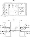
- the Ethernet bridge 1 is illustrated in Fig. 1 which may be connected to a plurality of separate Ethernet stations 2 and which implements the encapsulation of both Network Layer and Data Link Layer PDUs in a FPDU.
- the Ethernet bridge 1 generally comprises a multi-path network 10 in combination with a plurality of Ethernet ports 3 (only one is illustrated for the sake of clarity) with each port being individually connectable to an Ethernet station.
- the Ethernet ports 3 are generally conventional in design and each includes means for establishing a data connection with an Ethernet station, a receiving means or input 4 for performing Ethernet receive functions and a transmitting device or output 5 for performing Ethernet transmit functions.
- the Ethernet ports 3 are connected to a network interface 7 which provides conventional functionality such as packet buffering 6.
- the network interface 7 additionally includes an Ethernet PDU encapsulator 8 which connects the network interface 7 to ingress ports (not shown) of the network 10 and an Ethernet PDU decapsulator 9 which connects egress ports (not shown) of the network 10 back to the Ethernet ports 3.
- the Ethernet PDU encapsulator 8 implements the protocol of the Encapsulation Layer and thus is responsible for the generation of the FPDUs.
- each port 3 of the Ethernet bridge 1 has a respective network interface 7 and thus a respective Ethernet PDU encapsulator 8 and a respective Ethernet PDU decapsulator 9.
- the network 10 which is a proprietary multi-path network, comprises a plurality of interconnected network elements 18 referred to herein as bridge fabric switches (BFSs) interconnected by network links 17 in the form of bridge fabric switch links (BFSLs).
- BFSs bridge fabric switches
- BFSLs bridge fabric switch links
- Each BFSL is a bi-directional (full duplex) connection. Data is sent in each direction and acknowledgments and flow control state for data in one direction can be multiplexed with the data sent in the opposite direction of the BFSL.
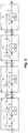
- Fig. 2 illustrates a BFLS 17 in combination with the input and output connections to the link 17.
- FPDU Fabric Protocol Data Units
- the multi-path network described herein preserves packet ordering whilst provides dynamic routing, and ideally adaptive routing, of FPDUs across the network and at the same time maximising usage of the bandwidth, even in larger networks. This is achieved, in part, by arranging for a packet acknowledgement to be released immediately the head of the FPDU is received at one or more egress ports. That is to say, release of the FPDU acknowledgement is not delayed until after the entire payload of the FPDU is received.
- the acknowledgement is already in transit back to the ingress port of the FPDU.
- Each BFSL of the network has a plurality of "flow channels" to support one or more source to destination connections simultaneously (where the source is defined as an ingress point to the network, and the destination is defined as an egress point (or points) from the network). Having many flow channels increases the amount of time a channel can be held open without having to wait for the acknowledgment to be returned.
- the round trip delay (the time taken for the head of a packet to cross the whole network and for the acknowledgement for that head to be returned back to the source port) can be 64 times larger than the time it takes to send a small FPDU before the BFSL will have to block sending output data.
- the full network source to destination flow of a FPDU uses a series of single flow channels each allocated in turn on each BFSL the FPDU visits as it crosses the network. Whilst the particular flow channel used by an FPDU might differ for each individual BFSL visited, during transit of the FPDU across the network, each flow channel entry on a BFSL has enough state to map the corresponding flow channel of the previous BFSL the FPDU used to arrive at the current flow channel entry. As a result the network, as a whole, records the path of the FPDU as it crosses the network from source to destination.
- Fig. 3 illustrates a path from a network ingress port 4 to a network egress port 5.
- FIG. 3 separate flow channels are shown which support the FPDU communication.
- the first flow channel is wholly in the first BFS 18 next to the ingress port 4.
- the other three flow channels straddle the BFSL between each of the BFS 18.
- Fig. 3 only the FPDU channel 17 and the acknowledgment path 16 are shown although it is expected that a full duplex BFSL would normally be used as shown in Figs. 2 and 4 .
- Each flow channel is mapped onto a BFSL 17 and each BFS at each end of the BFSL 17 includes a first state table 11 in the form of an output flow channel table (OFCT) and a second state table 12 in the form of an input flow channel table (IFCT) in which entries specific to each flow channel of the BFSL 17 are recorded and stored until over-written.
- Each location in the OFCT 11 has an associated location in the IFCT 12 in the form of a directly corresponding location in the IFCT 12.
- OFCT entry 3 corresponds to IFCT entry 3.
- some of the IFCT state is a copy of the OFCT state and some of the OFCT state is a copy of the IFCT state.
- output data 13 is multiplexed with acknowledgment values 16 relating to FPDUs transmitted in the opposite direction to create the BFSL data stream and at the next BFS 18 the input data 15 to the BFS 18 is separated from acknowledgments 16 concerning FPDUs transmitted in the other direction.
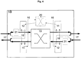
- FPDUs received from a BFSL are buffered in a buffering device 21, preferably a FIFO, while they wait to make a connection to the data crossbar switch 19.
- the flow channel number of the received acknowledgments 16 is used to index the OFCT 11 to retrieve the mapping of the previous BFSL and this is appended to form a routable acknowledgment 14 that is sent to the acknowledgment crossbar switch 20 shown in Figs. 3 and 4 .
- a "source to destination" connection is dynamically established across the whole network as a first FPDU travels across the network and then remains exclusively allocated to subsequent FPDUs having the same ordering requirement whilst any preceding FPDUs with the same ordering requirements remains in transit.
- the ordering requirements may be, but are not limited to the following: a source to destination address, with or without a level of priority; a message class; VLANS; higher level protocol requirements; IP numbers; or quality of service.
- This is achieved by storing in the OFCT 11 a destination address value and state which describes the upstream path, back towards the source ingress port, for the most recent FPDU transmitted by a flow channel of the BFSL 17.
- a plurality of destination address values and states for a plurality of FPDUs are stored each destination address value and state being stored in association with a respective flow channel of the BFSL.
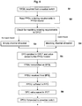
- Fig. 5 the basic methodology for transmitting an FPDU on one or more BFSLs of a plurality of BFSLs of a network fabric, are illustrated.
- a new FPDU is received S1 for transmission on the BFSL 17
- the header data of the new FPDU is checked S2 to see if the FPDU's ordering requirements match any of the valid channels of that BFSL.
- This match is executed by performing a parallel compare of all the entries in the OFCT 11.
- Each compare is an equality test between the ordering requirement in the header of the FPDU and the ordering requirement stored in the OFCT 11.
- Each compare also requires an equality test of the source port and source flow channel the FPDU has come from.
- an empty/unused channel is allocated S3 and the input port of the BFS, the flow channel of the BFSL and ordering requirement data of the FPDU are stored in relation to the allocated channel in the OFCT 11.
- the empty/unused channel may be allocated by the BFS randomly or quasi-randomly or may be allocated using one or more predefined rules. If a match does exist, then the FPDU is allocated the same flow channel S4 that most recently carried a previous FPDU with matching ordering requirement data. The state of the allocated channel is then updated in the OFCT 11 with information representative of the new FPDU (which is described in greater detail below).
- Fig. 4 shows how the individual flow channels of a BFSL are mapped into a BFS 18.
- Each BFS 18 has a data crossbar switch 19 that is used to transport data from an input BFSL 17 to an output BFSL 17.
- Each BFS 18 also has an acknowledgment crossbar switch 20, in parallel with the data crossbar switch 19, which is used to return BFSL acknowledgment tokens back from a network egress port to the network ingress port.
- the OFCT 11 holds for each flow channel the return address for the most recently transmitted FPDU. This return address is in two parts: it has the port number the FPDU came from and also the flow channel assigned on the previous BFSL.
- the return address is used for the acknowledgement token of that FPDU to direct the acknowledgment from the BFS data output port through the acknowledgment crossbar switch 18 into the IFCT 12 where it can be directed as a new acknowledgement token back to the next BFS in the acknowledgement's return path towards the ingress port for that FPDU.
- Each flow channel is assigned a count value representative of the number of units of data transmitted which is referred to herein as the Data Flow Count (DFC).
- the DFC value is incremented by the size of the FPDU being transmitted.
- the count value of each of the flow channels is held at both ends of the BFSL 17.
- the DFC has a master value at the sending end of the BFSL and a slave (copy) value at the receiving end. Thus, for data the master DFC value is held in the OFCT 11 and the slave DFC value is held in the IFCT 12.
- Each flow channel is also assigned a count value representative of the number of acknowledged units of data which is referred to herein as the Acknowledgement Flow Count (AFC).
- AFC Acknowledgement Flow Count
- the AFC master value is held in the IFCT 12 and the AFC slave value is held in the OFCT 11.
- the DFC reaches a predetermined maximum value it simply wraps back through zero. Overflow on the DFC is acceptable as it is only ever compared against the AFC that will also wrap back through zero in the same way as it is assigned the same predetermined maximum value.
- the unit measure of data is set as a predetermined number of bytes. This unit measure is set small enough to give reasonable resolution but big enough to minimise state and overhead on the size of headers in the FPDUs and the size of the acknowledgements returned. In one embodiment it is envisaged that the count values correspond to a count of whole FPDUs, instead of the total data size held in the FPDUs. This gives the same understanding of FPDU ordering but removes the knowledge of total data against the flow channel.
- the number of units of data being sent in the FPDU is calculated from the size field in the FPDU header.
- the master DFC value stored in the OFCT 11 in relation to the flow channel allocated to that FPDU is then incremented by the number of units of data being sent in the FPDU.
- the new DFC value is inserted into the header of the FPDU S5 for transmission on the BFSL 17.
- the DFC value is read from the FPDU header and loaded S6 into the slave data flow count value held in the IFCT 12 of that BFS.
- a similar rolling count value is established in relation to the returning acknowledgement which is described in greater detail below.
- the channel count value is calculated by taking the difference between the two rolling count values that are part of the state of the flow channel.
- all the DFC and AFC stored in the OFCT 11 and the IFCT 12 are initialised to the same value making the difference between the rolling count values equal to zero. Once initialised the DFC and AFC values are then only changed by the passing FPDU data and acknowledgments using the BFSL.
- an acknowledgement is immediately returned. As mentioned earlier, issuance of the acknowledgement is not delayed pending receipt of the entire payload of the FPDU.
- the acknowledgement is automatically routed back to the original ingress port following in reverse the path taken by the FPDU in the forward direction. This is done using the input port number and input flow channel number stored in each of the OFCTs 11.
- the acknowledgement includes information taken from the header of the FPDU that generated the acknowledgement on the unit size value of the FPDU. As illustrated in Fig. 6 , during the transit of the acknowledgement across the network fabric back to the ingress port, at each BFSL 17 in the reverse path the second rolling master AFC value, stored in the IFCT 12 is adjusted by the size value held in the returning acknowledgement S8. Likewise, this master AFC value is included in the acknowledgment token returned on the BFSL 17 and is loaded into the slave AFC value held in the OFCT 11 S9.
- the difference between the two rolling counts indicates the total amount of unacknowledged data.
- the values can be compared S10 in either the OFCT 11 or the IFCT 12. It should be noted that, due to the transmission delay along a BFSL the DFC value is updated in the OFCT 11 before it is copied into the IFCT 12 and likewise the AFC is updated in the IFCT 12 before it is copied into the OFCT 11. This has the effect of making the comparison of the Master DFC value and the Slave AFC in the OFCT 11 appear to be different for longer than the comparison of the Slave DFC value and the Master AFC value in the IFCT 12.
- the difference between the counts is not zero S12, then it is not safe to adaptively route a new FPDU having the same ordering requirements as there is a risk that it might arrive at the egress port out of order.
- the new FPDU must be routed along the same path, using the same flow channel, as the previous FPDU for this source/destination. This is done by using the destination port number or other number with ordering requirements stored in the IFCT 12 which was loaded the first time a connection was made on the data crossbar 19 for an FPDU having the same ordering requirements.
- dynamic routing is desirable. This is because dynamic routing significantly improves the total usable bandwidth of a network when unpredictable or irregular network connections are made as it allows the PDUs to be routed around localised congestion hot spots.
- dynamic routing can be used at an early stage in the delivery of the FPDU where many output ports of a BFS can be considered as a reasonable choice to deliver the FPDU closer to its destination.
- dynamic routing is selectively disabled for a series of FPDUs having a common ordering requirement where no acknowledgement has been received, in order to maintain packet ordering.
- the FPDU can be the subject of conventional dynamic / adaptive routing.
- the data crossbar switch 19 of the receiving BFS 18 will connect to any one of the permissible output ports.
- the number of the successful output port number is then communicated back to the BFSL input port so that it can be loaded as an entry in the IFCT 12. This ensures that a subsequent FPDU that arrives on the same flow channel will be directed to the same output port if the acknowledgement of the first FPDU has not yet been received.
- FPDUs With the network fabric described herein many small FPDUs can be sent into an adaptive network fabric and the FPDUs will all be delivered in the same order when they have the same ordering requirement. Any FPDUs being sent from a different source or being sent to a different destination or where there is no ordering requirement will also be adaptively routed giving better performance overall for the network. For large FPDUs as receipt of the header will be acknowledged before the end of the FPDU is sent, this allows the next FPDU to be adaptively routed by those BFSLs which have received the acknowledgement as it follows the return path back to the ingress port of the large FPDU.
- BFSLs closer to the destination are more likely to have all their FPDUs fully acknowledged as the FPDUs arrive here later and the acknowledgement will pass earlier. So even if BFSLs close to the source are unable to adaptively route, later stages may still be able to send the FPDUs a different way across the network. Thus a single FPDU may experience predefined routing close to the ingress port of the network but may then become subject to dynamic routing as it approaches its egress port or ports.
- each flow channel has the count value in two parts: this makes them more robust to errors on the individual BFSLs.
- the first value of the count is sent in the header of the FPDU and the second value of the count is sent with the acknowledgement token. If an error occurs, corrupting the header of the FPDU, or the acknowledgement then the value can be safely discarded and then resent later either with the next FPDU/acknowledgement or as a regular update without breaking the true value of outstanding unacknowledged FPDU data.
- the number of individually selectable flow channels for each BFSL is determined so that the return latency of many small FPDUs, sent to different destinations, can be hidden in a reasonably large network without significantly reducing the bandwidth. This calculation needs to take into account the size of the smallest FPDUs, the bandwidth of individual BFSLs and the latency of transmission across the BFS components and along each BFSL.
- an adaptive re-selection can be forced. This would cause the FPDU data stream to take another route across the network and perhaps avoid the congestion.
- the FPDU data stream is blocked at a BFS until all the previously sent FPDUs have been acknowledged and the flow channel appears empty. This blocking is achieved by preventing any new data connections from being made across the data crossbar switch 19. The blocked FPDUs will be buffered in the data input FIFO 21 waiting to connect to the data crossbar switch 19.
- All the FPDUs already sent across the crossbar switch will eventually reach the network egress ports and then all the acknowledgments will be returned.
- the last acknowledgment arrives back at the IFCT next to the blocked data flow it is safe to re-adaptively route the FPDU on the crossbar of the BFS and unblock the data stream.
- the flow channels used on the BFSLs before the blocking BFS will not appear empty while data is buffered in the data input FIFO.
- the features of the method and the network described above do not address network functionality for managing the point of congestion nor is the network functionality for managing a failure within the network fabric described.
- the scope of the present invention presumes successful, albeit possibly delayed, delivery.
- the subject of the present invention is the propagation of packet delivery knowledge across but within the network fabric to preserve packet ordering.
- the present invention is also concerned with the dynamic routing of FPDUs across the network in combination with the disabling of dynamic routing functionality where a series of FPDUs having the same ordering requirement are input to the network.
- the mechanism for packet ordering is embedded within the network fabric and as such is transparent to all devices external of the actual fabric. No packet ordering functionality is required in advance of an FPDU being supplied to an ingress port of the network.
- the delivery acknowledgements are not communicated beyond the ports of the network fabric and indeed it is not necessary for acknowledgements to be transmitted all the way back to the ingress port of the network.
- the furthermost BFS in any path through the network fabric requiring an acknowledgement is the first BFS after the ingress port.
- the minimum data contained in the acknowledgement consists of the unit size of the FPDU being acknowledged.
- the delivery acknowledgement does not contain any of the payload of the FPDU. It also does not contain the source or ordering values of the FPDU it is acknowledging nor its own source and/or destination. All other necessary information arises inherently from the path followed by the acknowledgement.
- the size of the acknowledgement is minimised through the use of the flow channel data stored in the OFCT 11 and the IFCT 12 at each BFS.
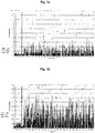
- FIG. 7a is a graphical representation of the results of computer modelling of the performance of a conventional Ethernet bridge having 512 egress ports. The performance is measured in terms of the percentage usage of the peak bandwidth of each egress port.
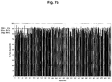
- Figs. 7b and 7c equivalent performance modelling is illustrated in respect of a known proprietary, non-Ethernet, bridge and an Ethernet bridge in accordance with the present invention, respectively. As these figures show, the performance average for a conventional Ethernet bridge is as little as 10%. Even with proprietary bridges the performance average remain low at 28% albeit with a much greater variation in performance across individual channels and a much higher maximum achievable occasionally.
- the performance average is a factor of in excess of eight times greater than that of a conventional Ethernet bridge and three times greater than the known proprietary network.
- the average performance achievable with the present invention is calculated to be 86% with a maximum performance of 94%.
- further developments to the present invention outside of the scope of this document anticipate further performance improvements with an average as high as 99%.
- the multi-path network described herein is truly scalable offering from 256 ports or fewer up to 48,000 ports or more.
- a single Ethernet bridge or router using the method described herein is capable of providing greatly increased connectivity in comparison to conventional Ethernet bridges. For example, currently the largest 10 Gbe Ethernet bridges (which are modular in construction) offer only 288 ports. With the network of the present invention, a single Ethernet bridge is possible which is capable of operating at 10Gbe or above and is capable of offering, for example, 48,000 ports.
- reference has been made herein to an Ethernet bridge or router it will, of course, be apparent that the present invention may be applied to any multi-path network which transports data packets between inputs and outputs to the network.
- the link channels may alternatively comprise a half duplex link channel with a sideband to allow acknowledgments to be transmitted in the opposing direction.
Claims (12)
- Procédé de transfert de paquets de données sur un réseau multivoies (10) ayant au moins un port d'entrée, une pluralité de ports de sortie, et une pluralité d'éléments (18) de réseau interconnectés par des liaisons réseau (17), le procédé comprenant :l'acheminement dynamique de paquets de données sur le réseau multivoies (10) à l'exception de quand le paquet de données a des exigences d'ordonnancement correspondant à un paquet de données précédent pour lequel une liaison (17) attribuée exclusivement existe, dans lequel acheminement dynamique signifie que lors de son transit sur le réseau (10), un paquet de données unique peut se voir attribuer des liaisons (17) précédemment sélectionnées par un premier groupe d'éléments (18) de réseau et peut se voir attribuer des liaisons (17) dynamiquement par un deuxième groupe d'éléments (18) de réseau ;pour chaque paquet de données arrivant à un port de sortie du réseau multivoies (10) par une voie de paquets de données sur le réseau multivoies (10), l'émission d'une confirmation de réception du port de sortie concerné, ladite voie de paquets de données connectant le port de sortie concerné avec un port d'entrée du réseau multivoies (10) par l'intermédiaire d'un ou plusieurs élément(s) (18) de réseau, chaque élément de réseau ayant une liaison réseau (17) connectée avec celui-ci sur laquelle le paquet de données est transmis depuis cet élément (18) de réseau ;le procédé étant caractérisé par :la transmission de la confirmation de réception sur le réseau multivoies (10) suivant en sens inverse ladite voie de paquets de données prise par le paquet de données étant confirmé ;au niveau du ou de chaque élément (18) de réseau dans ladite voie de paquets de données et en réponse à la réception d'une telle confirmation de réception par cet élément (18) de réseau, la mise à jour d'un état de cette liaison réseau (17) connectée avec l'élément (18) de réseau qui est dans ladite voie de paquets de données prise par le paquet de données étant confirmé ;l'attribution de la ou de chaque liaison réseau (17) dans la voie de paquets de données d'un premier paquet de données étant transmis sur le réseau individuellement exclusivement à des paquets de données suivants ayant la même exigence d'ordonnancement que ledit premier paquet de données jusqu'à ce qu'une confirmation de réception du paquet de données précédent le plus récent ayant la même exigence d'ordonnancement soit transmise sur une telle liaison réseau (17) attribuée exclusivement ; etla désactivation de l'acheminement dynamique de paquets de données par un élément (18) de réseau dans ladite voie de paquets de données de paquets de données qui ont des exigences d'ordonnancement correspondant à au moins un paquet de données précédent pour lequel aucune confirmation n'a été reçue par l'élément (18) de réseau concerné.
- Procédé selon la revendication 1, dans lequel chaque liaison réseau (18) dans le réseau multivoies (10) comprend une pluralité de canaux de liaison individuellement sélectionnables pour transmettre des paquets de données sur le réseau et dans lequel un canal de liaison peut être attribué individuellement exclusivement à des paquets de données ayant des exigences d'ordonnancement communes jusqu'à ce qu'au moins une confirmation d'un paquet de données soit transmise sur un tel canal de liaison exclusivement attribué.
- Procédé selon la revendication 2, dans lequel chaque élément (18) de réseau inclut au moins une table (11, 12), le procédé comprenant, pour chaque élément (18) de réseau : le stockage des exigences d'ordonnancement, pour ce qui concerne chaque canal de liaison, du paquet de données le plus récent transmis sur le canal de liaison.
- Procédé selon la revendication 3, comprenant en outre, dans chaque élément de réseau, le stockage additionnel, en association avec les exigences d'ordonnancement d'un paquet de données reçu par un élément (18) de réseau, du canal de liaison sur lequel le paquet de données arrive à un élément (18) de réseau.
- Procédé selon l'une quelconque des revendications 2 à 4, comprenant en outre, dans chaque élément (18) de réseau, le maintien d'une valeur de comptage de paquets en association avec chaque canal de liaison avec lequel il est connecté, la valeur de comptage de paquets étant ajustée incrémentiellement de quantités représentatives des paquets de données transmis sur le canal de liaison.
- Procédé selon l'une quelconque des revendications 3 à 5, comprenant en outre, dans chaque élément de réseau, le maintien d'une valeur de comptage de confirmations en association avec chaque canal de liaison avec lequel il est connecté, la valeur de comptage de confirmations étant ajustée incrémentiellement de quantités représentatives des paquets de données fournis à des ports de sortie de réseau transmis sur le canal de liaison.
- Réseau multivoies pour une utilisation dans un appareil de réseau, le réseau multivoies comprenant :au moins un port d'entrée ;une pluralité de ports de sortie de réseau ;une pluralité d'éléments (18) de réseau ; etune pluralité de liaisons réseau (17) interconnectant les éléments (18) de réseau et les ports de sortie de réseau pour transporter des paquets de données d'un port d'entrée à un port de sortie par l'intermédiaire de voies de données respectives ayant un ou plusieurs des éléments (18) deréseau et une ou plusieurs des liaisons réseau (17),dans lequel chaque port de sortie de réseau inclut un moyen de confirmation utilisable pour émettre une confirmation de réception en réponse à une réception d'un paquet de données par une voie de paquets de données sur le réseau multivoies, la voie de paquets de données connectant le port de sortie concerné avec un port d'entrée du réseau multivoies (10) par l'intermédiaire d'un ou plusieurs des éléments (18) de réseau, chaque tel élément (18) de réseau ayant une liaison réseau (17) connectée avec celui-ci sur laquelle l'élément (18) de réseau est utilisable pour transmettre le paquet de données, caractérisé en ce que :chaque élément (18) de réseau est utilisable pour retransmettre, en réponse à la réception d'une telle confirmation de réception, une confirmation de réception dans un sens inverse le long de la voie de paquets de données prise par le paquet de données étant confirmé ;chaque élément (18) de réseau est utilisable pour mettre à jour l'état de cette liaison réseau (17) dans la voie de paquets de données à laquelle il est connecté en réponse à la réception d'une telle confirmation ;le réseau est utilisable pour attribuer la ou chaque liaison réseau (17) dans la voie de paquets de données d'un premier paquet de données étant transmis sur le réseau individuellement exclusivement à des paquets de données suivants ayant la même exigence d'ordonnancement que ledit premier paquet de données jusqu'à ce qu'une confirmation de réception du paquet de données précédent le plus récent ayant la même exigence d'ordonnancement soit transmise sur une telle liaison réseau (17) attribuée exclusivement ; etle réseau est utilisable pour désactiver l'acheminement dynamique de paquets de données par un élément (18) de réseau dans ladite voie de paquets de données de paquets de données qui ont des exigences d'ordonnancement correspondant à au moins un paquet de données précédent pour lequel aucune confirmation n'a été reçue par l'élément (18) de réseau concerné, dans lequel acheminement dynamique signifie que lors de son transit sur le réseau (10), un paquet de données unique peut se voir attribuer des liaisons (17) précédemment sélectionnées par un premier groupe d'éléments (18) de réseau et peut se voir attribuer des liaisons (17) dynamiquement par un deuxième groupe d'éléments (18) de réseau.
- Réseau multivoies selon la revendication 7, dans lequel chaque liaison réseau (17) dans le réseau multivoies (10) comprend une pluralité de canaux de liaison individuellement sélectionnables pour transmettre des paquets de données sur le réseau et dans lequel un canal de liaison peut être attribué individuellement exclusivement à des paquets de données ayant des exigences d'ordonnancement communes jusqu'à ce qu'au moins une confirmation d'un paquet de données soit transmise sur un tel canal de liaison exclusivement attribué.
- Réseau multivoies selon la revendication 8, dans lequel chaque élément (18) de réseau inclut au moins une table dans laquelle sont stockées les exigences d'ordonnancement, pour ce qui concerne chaque canal de liaison, d'un paquet de données le plus récent transmis sur le canal de liaison.
- Réseau multivoies selon la revendication 9, dans lequel ladite au moins une table est adaptée à stocker, en association avec les exigences d'ordonnancement d'un paquet de données reçu par un élément (18) de réseau, le canal de liaison sur lequel le paquet de données arrive à un élément (18) de réseau.
- Réseau multivoies selon l'une quelconque des revendications 7 à 10, dans lequel chaque élément (18) de réseau inclut en outre un moyen de comptage de paquets utilisable pour maintenir une valeur de comptage de paquets en association avec chaque canal de liaison avec lequel il est connecté, la valeur de comptage de paquets étant ajustée incrémentiellement de quantités représentatives des paquets de données transmis sur le canal de liaison.
- Réseau multivoies selon l'une quelconque des revendications 7 à 10, dans lequel chaque élément (18) de réseau inclut en outre un moyen de comptage de confirmations utilisable pour maintenir une valeur de comptage de confirmations en association avec chaque canal de liaison avec lequel il est connecté, la valeur de comptage de confirmations étant ajustée incrémentiellement de quantités représentatives des paquets de données fournis à des ports de sortie de réseau qui ont été transmis sur le canal de liaison.
Applications Claiming Priority (2)
| Application Number | Priority Date | Filing Date | Title |
|---|---|---|---|
| GB0808862A GB2460070B (en) | 2008-05-15 | 2008-05-15 | A method of data delivery across a network |
| PCT/GB2009/001202 WO2009138745A1 (fr) | 2008-05-15 | 2009-05-13 | Procédé de distribution de données sur l'ensemble d'un réseau |
Publications (3)
| Publication Number | Publication Date |
|---|---|
| EP2291960A1 EP2291960A1 (fr) | 2011-03-09 |
| EP2291960B1 true EP2291960B1 (fr) | 2017-12-13 |
| EP2291960B8 EP2291960B8 (fr) | 2018-02-14 |
Family
ID=39595965
Family Applications (1)
| Application Number | Title | Priority Date | Filing Date |
|---|---|---|---|
| EP09746062.0A Active EP2291960B8 (fr) | 2008-05-15 | 2009-05-13 | Procédé de distribution de données sur l'ensemble d'un réseau |
Country Status (5)
| Country | Link |
|---|---|
| US (2) | US8774063B2 (fr) |
| EP (1) | EP2291960B8 (fr) |
| CN (1) | CN102027717B (fr) |
| GB (1) | GB2460070B (fr) |
| WO (1) | WO2009138745A1 (fr) |
Families Citing this family (27)
| Publication number | Priority date | Publication date | Assignee | Title |
|---|---|---|---|---|
| GB2461132B (en) * | 2008-06-27 | 2013-02-13 | Gnodal Ltd | Method of data delivery across a network |
| WO2012124392A1 (fr) * | 2011-03-15 | 2012-09-20 | オムロン株式会社 | Système de réseau, dispositif maître et procédé permettant de commander un système de réseau |
| CN103166738B (zh) * | 2011-12-19 | 2018-02-27 | 中兴通讯股份有限公司 | 一种测量双端帧丢失的装置及方法 |
| US10230566B1 (en) | 2012-02-17 | 2019-03-12 | F5 Networks, Inc. | Methods for dynamically constructing a service principal name and devices thereof |
| WO2013163648A2 (fr) | 2012-04-27 | 2013-10-31 | F5 Networks, Inc. | Procédés destinés à optimiser un service de demandes de contenu, et dispositifs associés |
| US9548960B2 (en) | 2013-10-06 | 2017-01-17 | Mellanox Technologies Ltd. | Simplified packet routing |
| US10187317B1 (en) * | 2013-11-15 | 2019-01-22 | F5 Networks, Inc. | Methods for traffic rate control and devices thereof |
| US9729473B2 (en) | 2014-06-23 | 2017-08-08 | Mellanox Technologies, Ltd. | Network high availability using temporary re-routing |
| US9806994B2 (en) | 2014-06-24 | 2017-10-31 | Mellanox Technologies, Ltd. | Routing via multiple paths with efficient traffic distribution |
| US9699067B2 (en) | 2014-07-22 | 2017-07-04 | Mellanox Technologies, Ltd. | Dragonfly plus: communication over bipartite node groups connected by a mesh network |
| US9894005B2 (en) * | 2015-03-31 | 2018-02-13 | Mellanox Technologies, Ltd. | Adaptive routing controlled by source node |
| GB2538245B (en) * | 2015-05-11 | 2017-06-14 | Cirrus Logic Int Semiconductor Ltd | Digital accessory interface |
| US9954799B2 (en) | 2015-05-14 | 2018-04-24 | International Business Machines Corporation | Adaptive service chain management |
| US9973435B2 (en) | 2015-12-16 | 2018-05-15 | Mellanox Technologies Tlv Ltd. | Loopback-free adaptive routing |
| US10523796B2 (en) | 2015-12-22 | 2019-12-31 | Intel Corporation | Techniques for embedding fabric address information into locally-administered Ethernet media access control addresses (MACs) and a multi-node fabric system implementing the same |
| US9871725B2 (en) * | 2016-01-21 | 2018-01-16 | International Business Machines Corporation | Wireless data transfer as an alternative method to overcome errors or noise in a storage environment |
| US10819621B2 (en) | 2016-02-23 | 2020-10-27 | Mellanox Technologies Tlv Ltd. | Unicast forwarding of adaptive-routing notifications |
| US10178029B2 (en) | 2016-05-11 | 2019-01-08 | Mellanox Technologies Tlv Ltd. | Forwarding of adaptive routing notifications |
| CN106656812B (zh) * | 2016-12-13 | 2020-06-02 | 北京锐安科技有限公司 | 映射表的构建方法、分流设备的分流方法及相应装置 |
| US10200294B2 (en) | 2016-12-22 | 2019-02-05 | Mellanox Technologies Tlv Ltd. | Adaptive routing based on flow-control credits |
| US10644995B2 (en) | 2018-02-14 | 2020-05-05 | Mellanox Technologies Tlv Ltd. | Adaptive routing in a box |
| US11005724B1 (en) | 2019-01-06 | 2021-05-11 | Mellanox Technologies, Ltd. | Network topology having minimal number of long connections among groups of network elements |
| EP3949290A4 (fr) | 2019-05-23 | 2023-05-31 | Hewlett Packard Enterprise Development LP | Systèmes et procédés de routage adaptatif en présence de flux persistants |
| US11575594B2 (en) | 2020-09-10 | 2023-02-07 | Mellanox Technologies, Ltd. | Deadlock-free rerouting for resolving local link failures using detour paths |
| US11411911B2 (en) | 2020-10-26 | 2022-08-09 | Mellanox Technologies, Ltd. | Routing across multiple subnetworks using address mapping |
| US11870682B2 (en) | 2021-06-22 | 2024-01-09 | Mellanox Technologies, Ltd. | Deadlock-free local rerouting for handling multiple local link failures in hierarchical network topologies |
| US11765103B2 (en) | 2021-12-01 | 2023-09-19 | Mellanox Technologies, Ltd. | Large-scale network with high port utilization |
Citations (1)
| Publication number | Priority date | Publication date | Assignee | Title |
|---|---|---|---|---|
| US20050002334A1 (en) * | 2003-06-19 | 2005-01-06 | Hung-Hsiang Jonathan Chao | Packet sequence maintenance with load balancing, and head-of-line blocking avoidance in a switch |
Family Cites Families (19)
| Publication number | Priority date | Publication date | Assignee | Title |
|---|---|---|---|---|
| US4422171A (en) * | 1980-12-29 | 1983-12-20 | Allied Corporation, Law Department | Method and system for data communication |
| US4644468A (en) * | 1984-07-20 | 1987-02-17 | International Business Machines Corp. | Name usage support through distributed processing networks linked by bridges and/or gateways |
| US5237566A (en) * | 1989-03-30 | 1993-08-17 | Ungermann-Bass, Inc. | Network hub for maintaining node bandwidth in a single-node network |
| US5170393A (en) * | 1989-05-18 | 1992-12-08 | California Institute Of Technology | Adaptive routing of messages in parallel and distributed processor systems |
| US6493318B1 (en) * | 1998-05-04 | 2002-12-10 | Hewlett-Packard Company | Cost propagation switch protocols |
| JP2000032048A (ja) * | 1998-07-14 | 2000-01-28 | Fujitsu Ltd | ネットワーク装置 |
| DE69927252T2 (de) * | 1999-07-13 | 2006-06-29 | International Business Machines Corp. | Auf der Überwachung der Belegung von Puffern basierte Planung der Netzwerkkapazität |
| US6775707B1 (en) * | 1999-10-15 | 2004-08-10 | Fisher-Rosemount Systems, Inc. | Deferred acknowledgment communications and alarm management |
| US6587438B1 (en) * | 1999-12-22 | 2003-07-01 | Resonate Inc. | World-wide-web server that finds optimal path by sending multiple syn+ack packets to a single client |
| US20040152452A1 (en) * | 2000-03-02 | 2004-08-05 | Jones Edward Arthur | Paging method and apparatus with acknowledgement capability |
| US7007189B2 (en) * | 2001-05-07 | 2006-02-28 | Sun Microsystems, Inc. | Routing scheme using preferred paths in a multi-path interconnection fabric in a storage network |
| US7525960B2 (en) * | 2002-05-09 | 2009-04-28 | Alcatel-Lucent Canada Inc. | Methods and systems preventing frame mis-ordering in explicitly routed networks |
| DE10301265A1 (de) * | 2003-01-15 | 2004-07-29 | Siemens Ag | Verfahren und Anordnung zum Routing von Datenpaketen in einem paketvermittelnden Datennetz |
| US6839328B2 (en) * | 2003-01-31 | 2005-01-04 | Telcordia Technologies, Inc. | Measurement of packet loss ratio in a network using end-point data |
| US6973128B2 (en) * | 2003-02-21 | 2005-12-06 | Mitsubishi Electric Research Labs, Inc. | Multi-path transmission of fine-granular scalability video streams |
| US7656800B2 (en) * | 2004-07-30 | 2010-02-02 | Cisco Technology, Inc. | Transmission control protocol (TCP) |
| US7573821B2 (en) * | 2005-08-17 | 2009-08-11 | Intel Corporation | Data packet rate control |
| US7643427B2 (en) * | 2006-03-28 | 2010-01-05 | Nec Laboratories America, Inc. | Multipath routing architecture for large data transfers |
| CN101052024A (zh) * | 2007-05-18 | 2007-10-10 | 中兴通讯股份有限公司 | 一种边界网关协议策略选路的方法 |
-
2008
- 2008-05-15 GB GB0808862A patent/GB2460070B/en active Active
-
2009
- 2009-05-13 WO PCT/GB2009/001202 patent/WO2009138745A1/fr active Application Filing
- 2009-05-13 EP EP09746062.0A patent/EP2291960B8/fr active Active
- 2009-05-13 CN CN200980117289.2A patent/CN102027717B/zh active Active
- 2009-05-13 US US12/992,875 patent/US8774063B2/en active Active
-
2014
- 2014-05-23 US US14/286,553 patent/US9749204B2/en active Active
Patent Citations (1)
| Publication number | Priority date | Publication date | Assignee | Title |
|---|---|---|---|---|
| US20050002334A1 (en) * | 2003-06-19 | 2005-01-06 | Hung-Hsiang Jonathan Chao | Packet sequence maintenance with load balancing, and head-of-line blocking avoidance in a switch |
Also Published As
| Publication number | Publication date |
|---|---|
| GB2460070B (en) | 2010-10-13 |
| GB0808862D0 (en) | 2008-06-25 |
| US20140348007A1 (en) | 2014-11-27 |
| WO2009138745A1 (fr) | 2009-11-19 |
| CN102027717A (zh) | 2011-04-20 |
| EP2291960B8 (fr) | 2018-02-14 |
| CN102027717B (zh) | 2016-08-24 |
| EP2291960A1 (fr) | 2011-03-09 |
| US9749204B2 (en) | 2017-08-29 |
| US20110075592A1 (en) | 2011-03-31 |
| GB2460070A (en) | 2009-11-18 |
| US8774063B2 (en) | 2014-07-08 |
Similar Documents
| Publication | Publication Date | Title |
|---|---|---|
| US9749204B2 (en) | Method of data delivery across a network | |
| US9729450B2 (en) | Method of data delivery across a network | |
| US8917741B2 (en) | Method of data delivery across a network | |
| US9954800B2 (en) | Multi-path network with fault detection and dynamic adjustments | |
| US8625427B1 (en) | Multi-path switching with edge-to-edge flow control | |
| US9426085B1 (en) | Methods and apparatus for multi-path flow control within a multi-stage switch fabric | |
| JP5827413B2 (ja) | 多配送ルートパケット順序付け | |
| US7443845B2 (en) | Apparatus and method for a lightweight, reliable, packet-based transport protocol | |
| US9401876B2 (en) | Method of data delivery across a network fabric in a router or Ethernet bridge | |
| US20140169169A1 (en) | Routing support for lossless data traffic | |
| EP2359547A1 (fr) | Réseau multivoie | |
| US7577136B1 (en) | Ethernet switch fabric interface | |
| EP3563535B1 (fr) | Transmission de messages par des composantes d'accélération configurées pour accélérer un service | |
| CN1456004A (zh) | 在网络交换机内的可编程第三层地址自我学习方法 | |
| Alghamdi | Layer 2 Switch Implementation with Programmable Logic Devices |
Legal Events
| Date | Code | Title | Description |
|---|---|---|---|
| PUAI | Public reference made under article 153(3) epc to a published international application that has entered the european phase |
Free format text: ORIGINAL CODE: 0009012 |
|
| 17P | Request for examination filed |
Effective date: 20101124 |
|
| AK | Designated contracting states |
Kind code of ref document: A1 Designated state(s): AT BE BG CH CY CZ DE DK EE ES FI FR GB GR HR HU IE IS IT LI LT LU LV MC MK MT NL NO PL PT RO SE SI SK TR |
|
| AX | Request for extension of the european patent |
Extension state: AL BA RS |
|
| DAX | Request for extension of the european patent (deleted) | ||
| REG | Reference to a national code |
Ref country code: HK Ref legal event code: DE Ref document number: 1155295 Country of ref document: HK |
|
| 17Q | First examination report despatched |
Effective date: 20130726 |
|
| 19U | Interruption of proceedings before grant |
Effective date: 20131004 |
|
| 19W | Proceedings resumed before grant after interruption of proceedings |
Effective date: 20140303 |
|
| RAP1 | Party data changed (applicant data changed or rights of an application transferred) |
Owner name: CRAY UK LIMITED |
|
| REG | Reference to a national code |
Ref country code: DE Ref legal event code: R079 Ref document number: 602009049882 Country of ref document: DE Free format text: PREVIOUS MAIN CLASS: H04L0012560000 Ipc: H04L0012460000 |
|
| GRAP | Despatch of communication of intention to grant a patent |
Free format text: ORIGINAL CODE: EPIDOSNIGR1 |
|
| RIC1 | Information provided on ipc code assigned before grant |
Ipc: H04L 12/803 20130101ALI20170803BHEP Ipc: H04L 1/16 20060101ALI20170803BHEP Ipc: H04L 12/721 20130101ALI20170803BHEP Ipc: H04L 12/931 20130101ALN20170803BHEP Ipc: H04L 12/933 20130101ALN20170803BHEP Ipc: H04L 12/707 20130101ALI20170803BHEP Ipc: H04L 1/00 20060101ALN20170803BHEP Ipc: H04L 12/46 20060101AFI20170803BHEP Ipc: H04L 12/26 20060101ALI20170803BHEP |
|
| INTG | Intention to grant announced |
Effective date: 20170821 |
|
| GRAS | Grant fee paid |
Free format text: ORIGINAL CODE: EPIDOSNIGR3 |
|
| GRAA | (expected) grant |
Free format text: ORIGINAL CODE: 0009210 |
|
| AK | Designated contracting states |
Kind code of ref document: B1 Designated state(s): AT BE BG CH CY CZ DE DK EE ES FI FR GB GR HR HU IE IS IT LI LT LU LV MC MK MT NL NO PL PT RO SE SI SK TR |
|
| REG | Reference to a national code |
Ref country code: GB Ref legal event code: FG4D |
|
| REG | Reference to a national code |
Ref country code: AT Ref legal event code: REF Ref document number: 955327 Country of ref document: AT Kind code of ref document: T Effective date: 20171215 Ref country code: CH Ref legal event code: EP |
|
| REG | Reference to a national code |
Ref country code: IE Ref legal event code: FG4D |
|
| REG | Reference to a national code |
Ref country code: DE Ref legal event code: R096 Ref document number: 602009049882 Country of ref document: DE |
|
| RAP2 | Party data changed (patent owner data changed or rights of a patent transferred) |
Owner name: CRAY UK LIMITED |
|
| REG | Reference to a national code |
Ref country code: DE Ref legal event code: R081 Ref document number: 602009049882 Country of ref document: DE Owner name: HEWLETT PACKARD ENTERPRISE DEVELOPEMENT LP, HO, US Free format text: FORMER OWNER: CRAY UK LTD., THEALE, READING, GB Ref country code: DE Ref legal event code: R082 Ref document number: 602009049882 Country of ref document: DE Representative=s name: OFFICE FREYLINGER S.A., LU Ref country code: DE Ref legal event code: R082 Ref document number: 602009049882 Country of ref document: DE Ref country code: DE Ref legal event code: R082 Ref document number: 602009049882 Country of ref document: DE Representative=s name: PROCK, THOMAS, DR., GB |
|
| REG | Reference to a national code |
Ref country code: DE Ref legal event code: R082 Ref document number: 602009049882 Country of ref document: DE Representative=s name: PROCK, THOMAS, DR., GB |
|
| REG | Reference to a national code |
Ref country code: NL Ref legal event code: MP Effective date: 20171213 |
|
| REG | Reference to a national code |
Ref country code: LT Ref legal event code: MG4D |
|
| PG25 | Lapsed in a contracting state [announced via postgrant information from national office to epo] |
Ref country code: SE Free format text: LAPSE BECAUSE OF FAILURE TO SUBMIT A TRANSLATION OF THE DESCRIPTION OR TO PAY THE FEE WITHIN THE PRESCRIBED TIME-LIMIT Effective date: 20171213 Ref country code: NO Free format text: LAPSE BECAUSE OF FAILURE TO SUBMIT A TRANSLATION OF THE DESCRIPTION OR TO PAY THE FEE WITHIN THE PRESCRIBED TIME-LIMIT Effective date: 20180313 Ref country code: FI Free format text: LAPSE BECAUSE OF FAILURE TO SUBMIT A TRANSLATION OF THE DESCRIPTION OR TO PAY THE FEE WITHIN THE PRESCRIBED TIME-LIMIT Effective date: 20171213 Ref country code: LT Free format text: LAPSE BECAUSE OF FAILURE TO SUBMIT A TRANSLATION OF THE DESCRIPTION OR TO PAY THE FEE WITHIN THE PRESCRIBED TIME-LIMIT Effective date: 20171213 |
|
| REG | Reference to a national code |
Ref country code: AT Ref legal event code: MK05 Ref document number: 955327 Country of ref document: AT Kind code of ref document: T Effective date: 20171213 |
|
| REG | Reference to a national code |
Ref country code: FR Ref legal event code: PLFP Year of fee payment: 10 |
|
| PG25 | Lapsed in a contracting state [announced via postgrant information from national office to epo] |
Ref country code: GR Free format text: LAPSE BECAUSE OF FAILURE TO SUBMIT A TRANSLATION OF THE DESCRIPTION OR TO PAY THE FEE WITHIN THE PRESCRIBED TIME-LIMIT Effective date: 20180314 Ref country code: LV Free format text: LAPSE BECAUSE OF FAILURE TO SUBMIT A TRANSLATION OF THE DESCRIPTION OR TO PAY THE FEE WITHIN THE PRESCRIBED TIME-LIMIT Effective date: 20171213 Ref country code: HR Free format text: LAPSE BECAUSE OF FAILURE TO SUBMIT A TRANSLATION OF THE DESCRIPTION OR TO PAY THE FEE WITHIN THE PRESCRIBED TIME-LIMIT Effective date: 20171213 Ref country code: BG Free format text: LAPSE BECAUSE OF FAILURE TO SUBMIT A TRANSLATION OF THE DESCRIPTION OR TO PAY THE FEE WITHIN THE PRESCRIBED TIME-LIMIT Effective date: 20180313 |
|
| PG25 | Lapsed in a contracting state [announced via postgrant information from national office to epo] |
Ref country code: NL Free format text: LAPSE BECAUSE OF FAILURE TO SUBMIT A TRANSLATION OF THE DESCRIPTION OR TO PAY THE FEE WITHIN THE PRESCRIBED TIME-LIMIT Effective date: 20171213 |
|
| PG25 | Lapsed in a contracting state [announced via postgrant information from national office to epo] |
Ref country code: ES Free format text: LAPSE BECAUSE OF FAILURE TO SUBMIT A TRANSLATION OF THE DESCRIPTION OR TO PAY THE FEE WITHIN THE PRESCRIBED TIME-LIMIT Effective date: 20171213 Ref country code: SK Free format text: LAPSE BECAUSE OF FAILURE TO SUBMIT A TRANSLATION OF THE DESCRIPTION OR TO PAY THE FEE WITHIN THE PRESCRIBED TIME-LIMIT Effective date: 20171213 Ref country code: CZ Free format text: LAPSE BECAUSE OF FAILURE TO SUBMIT A TRANSLATION OF THE DESCRIPTION OR TO PAY THE FEE WITHIN THE PRESCRIBED TIME-LIMIT Effective date: 20171213 Ref country code: EE Free format text: LAPSE BECAUSE OF FAILURE TO SUBMIT A TRANSLATION OF THE DESCRIPTION OR TO PAY THE FEE WITHIN THE PRESCRIBED TIME-LIMIT Effective date: 20171213 Ref country code: CY Free format text: LAPSE BECAUSE OF FAILURE TO SUBMIT A TRANSLATION OF THE DESCRIPTION OR TO PAY THE FEE WITHIN THE PRESCRIBED TIME-LIMIT Effective date: 20171213 |
|
| PG25 | Lapsed in a contracting state [announced via postgrant information from national office to epo] |
Ref country code: PL Free format text: LAPSE BECAUSE OF FAILURE TO SUBMIT A TRANSLATION OF THE DESCRIPTION OR TO PAY THE FEE WITHIN THE PRESCRIBED TIME-LIMIT Effective date: 20171213 Ref country code: IS Free format text: LAPSE BECAUSE OF FAILURE TO SUBMIT A TRANSLATION OF THE DESCRIPTION OR TO PAY THE FEE WITHIN THE PRESCRIBED TIME-LIMIT Effective date: 20180413 Ref country code: IT Free format text: LAPSE BECAUSE OF FAILURE TO SUBMIT A TRANSLATION OF THE DESCRIPTION OR TO PAY THE FEE WITHIN THE PRESCRIBED TIME-LIMIT Effective date: 20171213 Ref country code: AT Free format text: LAPSE BECAUSE OF FAILURE TO SUBMIT A TRANSLATION OF THE DESCRIPTION OR TO PAY THE FEE WITHIN THE PRESCRIBED TIME-LIMIT Effective date: 20171213 Ref country code: RO Free format text: LAPSE BECAUSE OF FAILURE TO SUBMIT A TRANSLATION OF THE DESCRIPTION OR TO PAY THE FEE WITHIN THE PRESCRIBED TIME-LIMIT Effective date: 20171213 |
|
| REG | Reference to a national code |
Ref country code: DE Ref legal event code: R097 Ref document number: 602009049882 Country of ref document: DE |
|
| REG | Reference to a national code |
Ref country code: FR Ref legal event code: CA Effective date: 20180831 |
|
| PLBE | No opposition filed within time limit |
Free format text: ORIGINAL CODE: 0009261 |
|
| STAA | Information on the status of an ep patent application or granted ep patent |
Free format text: STATUS: NO OPPOSITION FILED WITHIN TIME LIMIT |
|
| REG | Reference to a national code |
Ref country code: HK Ref legal event code: GR Ref document number: 1155295 Country of ref document: HK |
|
| 26N | No opposition filed |
Effective date: 20180914 |
|
| PG25 | Lapsed in a contracting state [announced via postgrant information from national office to epo] |
Ref country code: DK Free format text: LAPSE BECAUSE OF FAILURE TO SUBMIT A TRANSLATION OF THE DESCRIPTION OR TO PAY THE FEE WITHIN THE PRESCRIBED TIME-LIMIT Effective date: 20171213 |
|
| REG | Reference to a national code |
Ref country code: CH Ref legal event code: PL |
|
| REG | Reference to a national code |
Ref country code: BE Ref legal event code: MM Effective date: 20180531 |
|
| PG25 | Lapsed in a contracting state [announced via postgrant information from national office to epo] |
Ref country code: MC Free format text: LAPSE BECAUSE OF FAILURE TO SUBMIT A TRANSLATION OF THE DESCRIPTION OR TO PAY THE FEE WITHIN THE PRESCRIBED TIME-LIMIT Effective date: 20171213 |
|
| REG | Reference to a national code |
Ref country code: IE Ref legal event code: MM4A |
|
| PG25 | Lapsed in a contracting state [announced via postgrant information from national office to epo] |
Ref country code: CH Free format text: LAPSE BECAUSE OF NON-PAYMENT OF DUE FEES Effective date: 20180531 Ref country code: LI Free format text: LAPSE BECAUSE OF NON-PAYMENT OF DUE FEES Effective date: 20180531 Ref country code: SI Free format text: LAPSE BECAUSE OF FAILURE TO SUBMIT A TRANSLATION OF THE DESCRIPTION OR TO PAY THE FEE WITHIN THE PRESCRIBED TIME-LIMIT Effective date: 20171213 |
|
| PG25 | Lapsed in a contracting state [announced via postgrant information from national office to epo] |
Ref country code: LU Free format text: LAPSE BECAUSE OF NON-PAYMENT OF DUE FEES Effective date: 20180513 |
|
| PG25 | Lapsed in a contracting state [announced via postgrant information from national office to epo] |
Ref country code: IE Free format text: LAPSE BECAUSE OF NON-PAYMENT OF DUE FEES Effective date: 20180513 |
|
| PG25 | Lapsed in a contracting state [announced via postgrant information from national office to epo] |
Ref country code: BE Free format text: LAPSE BECAUSE OF NON-PAYMENT OF DUE FEES Effective date: 20180531 |
|
| PG25 | Lapsed in a contracting state [announced via postgrant information from national office to epo] |
Ref country code: MT Free format text: LAPSE BECAUSE OF NON-PAYMENT OF DUE FEES Effective date: 20180513 |
|
| PG25 | Lapsed in a contracting state [announced via postgrant information from national office to epo] |
Ref country code: TR Free format text: LAPSE BECAUSE OF FAILURE TO SUBMIT A TRANSLATION OF THE DESCRIPTION OR TO PAY THE FEE WITHIN THE PRESCRIBED TIME-LIMIT Effective date: 20171213 |
|
| PG25 | Lapsed in a contracting state [announced via postgrant information from national office to epo] |
Ref country code: PT Free format text: LAPSE BECAUSE OF FAILURE TO SUBMIT A TRANSLATION OF THE DESCRIPTION OR TO PAY THE FEE WITHIN THE PRESCRIBED TIME-LIMIT Effective date: 20171213 Ref country code: HU Free format text: LAPSE BECAUSE OF FAILURE TO SUBMIT A TRANSLATION OF THE DESCRIPTION OR TO PAY THE FEE WITHIN THE PRESCRIBED TIME-LIMIT; INVALID AB INITIO Effective date: 20090513 |
|
| PG25 | Lapsed in a contracting state [announced via postgrant information from national office to epo] |
Ref country code: MK Free format text: LAPSE BECAUSE OF NON-PAYMENT OF DUE FEES Effective date: 20171213 |
|
| REG | Reference to a national code |
Ref country code: DE Ref legal event code: R082 Ref document number: 602009049882 Country of ref document: DE Representative=s name: FLEUCHAUS & GALLO PARTNERSCHAFT MBB - PATENT- , DE Ref country code: DE Ref legal event code: R082 Ref document number: 602009049882 Country of ref document: DE Representative=s name: FLEUCHAUS & GALLO PARTNERSCHAFT MBB PATENTANWA, DE Ref country code: DE Ref legal event code: R082 Ref document number: 602009049882 Country of ref document: DE Representative=s name: PROCK, THOMAS, DR., GB |
|
| REG | Reference to a national code |
Ref country code: GB Ref legal event code: 732E Free format text: REGISTERED BETWEEN 20211021 AND 20211027 |
|
| REG | Reference to a national code |
Ref country code: DE Ref legal event code: R081 Ref document number: 602009049882 Country of ref document: DE Owner name: HEWLETT PACKARD ENTERPRISE DEVELOPEMENT LP, HO, US Free format text: FORMER OWNER: CRAY UK LTD., LONDON, GB |
|
| REG | Reference to a national code |
Ref country code: DE Ref legal event code: R082 Ref document number: 602009049882 Country of ref document: DE Representative=s name: FLEUCHAUS & GALLO PARTNERSCHAFT MBB - PATENT- , DE Ref country code: DE Ref legal event code: R082 Ref document number: 602009049882 Country of ref document: DE Representative=s name: FLEUCHAUS & GALLO PARTNERSCHAFT MBB PATENTANWA, DE |
|
| PGFP | Annual fee paid to national office [announced via postgrant information from national office to epo] |
Ref country code: FR Payment date: 20230523 Year of fee payment: 15 Ref country code: DE Payment date: 20230530 Year of fee payment: 15 |
|
| PGFP | Annual fee paid to national office [announced via postgrant information from national office to epo] |
Ref country code: GB Payment date: 20230523 Year of fee payment: 15 |