EP3484100A1 - Method and device for network access control - Google Patents
Method and device for network access control Download PDFInfo
- Publication number
- EP3484100A1 EP3484100A1 EP16910820.6A EP16910820A EP3484100A1 EP 3484100 A1 EP3484100 A1 EP 3484100A1 EP 16910820 A EP16910820 A EP 16910820A EP 3484100 A1 EP3484100 A1 EP 3484100A1
- Authority
- EP
- European Patent Office
- Prior art keywords
- network
- data connection
- terminal device
- network device
- status
- Prior art date
- Legal status (The legal status is an assumption and is not a legal conclusion. Google has not performed a legal analysis and makes no representation as to the accuracy of the status listed.)
- Pending
Links
- 238000000034 method Methods 0.000 title claims abstract description 256
- 238000012545 processing Methods 0.000 claims description 33
- 230000000977 initiatory effect Effects 0.000 claims 1
- 238000013461 design Methods 0.000 description 27
- 230000006870 function Effects 0.000 description 27
- 238000010586 diagram Methods 0.000 description 15
- 230000004044 response Effects 0.000 description 10
- 230000008569 process Effects 0.000 description 9
- 238000004590 computer program Methods 0.000 description 7
- 238000004891 communication Methods 0.000 description 5
- 230000007704 transition Effects 0.000 description 5
- 238000013475 authorization Methods 0.000 description 4
- 230000007774 longterm Effects 0.000 description 4
- 238000012986 modification Methods 0.000 description 4
- 230000004048 modification Effects 0.000 description 4
- 230000005540 biological transmission Effects 0.000 description 3
- 238000005516 engineering process Methods 0.000 description 3
- 238000000802 evaporation-induced self-assembly Methods 0.000 description 3
- 230000009977 dual effect Effects 0.000 description 2
- 238000010295 mobile communication Methods 0.000 description 2
- 230000003287 optical effect Effects 0.000 description 2
- 230000002093 peripheral effect Effects 0.000 description 2
- 239000013256 coordination polymer Substances 0.000 description 1
- 238000011161 development Methods 0.000 description 1
- 230000010354 integration Effects 0.000 description 1
- 230000003993 interaction Effects 0.000 description 1
- 230000011664 signaling Effects 0.000 description 1
Images


Classifications
-
- H—ELECTRICITY
- H04—ELECTRIC COMMUNICATION TECHNIQUE
- H04W—WIRELESS COMMUNICATION NETWORKS
- H04W36/00—Hand-off or reselection arrangements
- H04W36/0005—Control or signalling for completing the hand-off
- H04W36/0055—Transmission or use of information for re-establishing the radio link
- H04W36/0079—Transmission or use of information for re-establishing the radio link in case of hand-off failure or rejection
-
- H—ELECTRICITY
- H04—ELECTRIC COMMUNICATION TECHNIQUE
- H04W—WIRELESS COMMUNICATION NETWORKS
- H04W76/00—Connection management
- H04W76/30—Connection release
- H04W76/34—Selective release of ongoing connections
- H04W76/36—Selective release of ongoing connections for reassigning the resources associated with the released connections
-
- H—ELECTRICITY
- H04—ELECTRIC COMMUNICATION TECHNIQUE
- H04W—WIRELESS COMMUNICATION NETWORKS
- H04W36/00—Hand-off or reselection arrangements
- H04W36/0005—Control or signalling for completing the hand-off
- H04W36/0055—Transmission or use of information for re-establishing the radio link
- H04W36/0069—Transmission or use of information for re-establishing the radio link in case of dual connectivity, e.g. decoupled uplink/downlink
-
- H—ELECTRICITY
- H04—ELECTRIC COMMUNICATION TECHNIQUE
- H04W—WIRELESS COMMUNICATION NETWORKS
- H04W48/00—Access restriction; Network selection; Access point selection
- H04W48/02—Access restriction performed under specific conditions
-
- H—ELECTRICITY
- H04—ELECTRIC COMMUNICATION TECHNIQUE
- H04W—WIRELESS COMMUNICATION NETWORKS
- H04W76/00—Connection management
- H04W76/10—Connection setup
- H04W76/15—Setup of multiple wireless link connections
- H04W76/16—Involving different core network technologies, e.g. a packet-switched [PS] bearer in combination with a circuit-switched [CS] bearer
-
- H—ELECTRICITY
- H04—ELECTRIC COMMUNICATION TECHNIQUE
- H04W—WIRELESS COMMUNICATION NETWORKS
- H04W76/00—Connection management
- H04W76/10—Connection setup
- H04W76/18—Management of setup rejection or failure
-
- H—ELECTRICITY
- H04—ELECTRIC COMMUNICATION TECHNIQUE
- H04W—WIRELESS COMMUNICATION NETWORKS
- H04W52/00—Power management, e.g. TPC [Transmission Power Control], power saving or power classes
- H04W52/02—Power saving arrangements
- H04W52/0209—Power saving arrangements in terminal devices
- H04W52/0225—Power saving arrangements in terminal devices using monitoring of external events, e.g. the presence of a signal
- H04W52/0238—Power saving arrangements in terminal devices using monitoring of external events, e.g. the presence of a signal where the received signal is an unwanted signal, e.g. interference or idle signal
-
- H—ELECTRICITY
- H04—ELECTRIC COMMUNICATION TECHNIQUE
- H04W—WIRELESS COMMUNICATION NETWORKS
- H04W60/00—Affiliation to network, e.g. registration; Terminating affiliation with the network, e.g. de-registration
-
- H—ELECTRICITY
- H04—ELECTRIC COMMUNICATION TECHNIQUE
- H04W—WIRELESS COMMUNICATION NETWORKS
- H04W76/00—Connection management
- H04W76/10—Connection setup
- H04W76/15—Setup of multiple wireless link connections
-
- H—ELECTRICITY
- H04—ELECTRIC COMMUNICATION TECHNIQUE
- H04W—WIRELESS COMMUNICATION NETWORKS
- H04W76/00—Connection management
- H04W76/20—Manipulation of established connections
- H04W76/27—Transitions between radio resource control [RRC] states
-
- H—ELECTRICITY
- H04—ELECTRIC COMMUNICATION TECHNIQUE
- H04W—WIRELESS COMMUNICATION NETWORKS
- H04W8/00—Network data management
- H04W8/26—Network addressing or numbering for mobility support
-
- Y—GENERAL TAGGING OF NEW TECHNOLOGICAL DEVELOPMENTS; GENERAL TAGGING OF CROSS-SECTIONAL TECHNOLOGIES SPANNING OVER SEVERAL SECTIONS OF THE IPC; TECHNICAL SUBJECTS COVERED BY FORMER USPC CROSS-REFERENCE ART COLLECTIONS [XRACs] AND DIGESTS
- Y02—TECHNOLOGIES OR APPLICATIONS FOR MITIGATION OR ADAPTATION AGAINST CLIMATE CHANGE
- Y02D—CLIMATE CHANGE MITIGATION TECHNOLOGIES IN INFORMATION AND COMMUNICATION TECHNOLOGIES [ICT], I.E. INFORMATION AND COMMUNICATION TECHNOLOGIES AIMING AT THE REDUCTION OF THEIR OWN ENERGY USE
- Y02D30/00—Reducing energy consumption in communication networks
- Y02D30/70—Reducing energy consumption in communication networks in wireless communication networks
Definitions
- This application relates to the field of communications technologies, and in particular, to a network access control method and an apparatus.
- terminal devices support access to a plurality of networks of different types.
- the terminal device cannot transmit data in parallel by using two or more networks.
- the terminal device transmits data by using one network (where the terminal device establishes a data connection to the network)
- a data connection between the terminal device and another network needs to be ended. For example, the terminal device is in an idle state in the another network.
- a terminal device can access a plurality of networks but cannot transmit data in parallel by using the plurality of networks, when the terminal device establishes a data connection to one network, and forcibly establishes a data connection to another network, some network connection errors or runtime errors of the terminal device occur. Consequently, data cannot be normally transmitted.
- a terminal device in dual connectivity (Dual Connectivity, DC) mode can access both a second access Long Term Evolution (Second Access Long Term Evolution, SALTE) network and a Long Term Evolution (Long Term Evolution, LTE) network.
- the terminal device can access the SALTE network only when the terminal device does not access the LTE network or the terminal device is in an idle state in the LTE network. If the terminal device forcibly accesses the SALTE network when the terminal device is in a connected state in the LTE network, a network connection error or a runtime error of the terminal device occurs.
- Embodiments of this application provide a network access control method and an apparatus, to resolve a prior-art problem that when a terminal device establishes a data connection to one network and forcibly establishes a data connection to another network, occurrence of some network connection errors or a runtime error of the terminal device is caused, and consequently, data cannot be normally transmitted.
- an embodiment of this application provides a network access control method, including:
- the first network device controls the terminal device to stop the establishment of the first data connection to the first network, or controls the terminal device to end the second data connection to the second network, to smoothly establish the first data connection to the first network, thereby ensuring that the terminal device can have a data connection to only one network, ensuring that the terminal device can normally transmit data, implementing network access control on the terminal device, and avoiding occurrence of a network connection error or a runtime error of the terminal device when the terminal device has a data connection to one network and forcibly establishes a data connection to another network.
- the first network device before the determining, by a first network device, that a second data connection exists between the terminal device and the second network, the first network device receives a data connection request for the first network sent by the terminal device; or the first network device receives a status query request sent by a fourth network device.
- the status query request is used to instruct the first network device to determine a status of the second data connection of the terminal device.
- the first network device determines, in the following two manners, that the second data connection exists between the terminal device and the second network, where the two manners include:
- the first network device can determine that the second data connection exists between the terminal device and the second network.
- the first network device may determine that the terminal device is in a connected state in the second network, to determine that the second data connection exists between the terminal device and the second network.
- the first network device may determine, according to the method, that the second data connection exists between the terminal device and the second network.
- the first network determines that the terminal device is in the connected state in the second network, to determine that the second data connection exists.
- the instructing, by the first network device, the terminal device to stop the establishment of the first data connection includes: sending, by the first network device, an access stop message to the terminal device, where the access stop message is used to instruct the terminal device to stop the establishment of the first data connection.
- the first network device controls the terminal device to stop the establishment of the first data connection to the first network, thereby ensuring that the terminal device can have a data connection to only one network, ensuring that the terminal device can normally transmit data, implementing network access control on the terminal device, and avoiding occurrence of a network connection error or a runtime error of the terminal device when the terminal device has a data connection to one network and forcibly establishes a data connection to another network.
- the access stop message includes a status error cause, and the status error cause is used to notify that the second data connection exists between the terminal device and the second network.
- the first network device can notify the terminal device of a reason for stopping the establishment of the first data connection.
- the first network device forwards the access stop message to the terminal device by using another network device.
- the another network device may be a device such as an HSS or a control plane network element.
- the first network device can smoothly send the access stop message to the terminal device.
- the instructing, by the first network device, the terminal device to end the second data connection includes: sending, by the first network device, a first switching request message to the terminal device, where the first switching request message is used to instruct the terminal device to switch a data connection of the terminal device from the second data connection to the first data connection.
- the first network device controls the terminal device to switch the second data connection to the first data connection, to smoothly establish the first data connection, thereby ensuring that the terminal device can have a data connection to only one network, ensuring that the terminal device can normally transmit data, implementing network access control on the terminal device, and avoiding occurrence of a network connection error or a runtime error of the terminal device when the terminal device has a data connection to one network and forcibly establishes a data connection to another network.
- the first switching request message includes a status error cause
- the status error cause is used to notify that the second data connection exists between the terminal device and the second network.
- the first network device can notify the terminal device of a reason for switching the second data connection.
- the first network device forwards the first switching request message to the terminal device by using another network device.
- the another network device may be a device such as an HSS or a control plane network element.
- the first network device can smoothly send the first switching request message to the terminal device.
- the first network device ends the second data connection in the following two manners:
- the first network device directly ends the second data connection, to smoothly establish the first data connection, thereby ensuring that the terminal device can have a data connection to only one network, ensuring that the terminal device can normally transmit data, implementing network access control on the terminal device, and avoiding occurrence of a network connection error or a runtime error of the terminal device when the terminal device has a data connection to one network and forcibly establishes a data connection to another network.
- the instructing, by the first network device, the second network device to end the second data connection includes: sending, by the first network device, a second switching request message to the second network device, where the second switching request message is used to instruct the second network device to switch a data connection of the terminal device from the second data connection to the first data connection.
- the first network device controls the second network device to end the second data connection, to smoothly establish the first data connection, thereby ensuring that the terminal device can have a data connection to only one network, ensuring that the terminal device can normally transmit data, implementing network access control on the terminal device, and avoiding occurrence of a network connection error or a runtime error of the terminal device when the terminal device has a data connection to one network and forcibly establishes a data connection to another network.
- the second switching request message includes a status error cause
- the status error cause is used to notify the second network device that the second data connection exists between the terminal device and the second network.
- the first network device can notify the second network device of a reason for switching the data connection of the terminal device.
- the first network device determines that no data connection exists between the terminal device and the second network; and the first network device performs a procedure of establishing the first data connection.
- the first network device determines that the terminal device is in an idle state in the second network, to determine that no data connection exists between the terminal device and the second network.
- the second network is an LTE network, according to the foregoing method, it can be determined that no data connection exists between the terminal device and the second network.
- the first network device determines that the terminal device is in the idle state in the second network, and determines that no data connection exists between the terminal device and the second network.
- the first network device includes a control plane network element or a home subscriber server HSS.
- an embodiment of this application provides a network access control method, including: after a terminal device requests to establish a first data connection to a first network, when the terminal device receives an access stop message sent by a first network device, stopping, by the terminal device, a procedure of establishing the first data connection, where the access stop message is used to instruct the terminal device to stop the establishment of the first data connection.
- the terminal device after the terminal device requests to establish the first data connection to the first network, the terminal device receives the access stop message sent by the first network device, and stops the procedure of establishing the first data connection, to avoid occurrence of a network connection error or a runtime error of the terminal device when a data connection is forcibly established to the first network.
- the access stop message includes a status error cause, and the status error cause is used to notify that the second data connection exists between the terminal device and the second network.
- the terminal device receives, by using another network device, the access stop message sent by the first network device.
- the another network device may be a device such as an HSS or a control plane network element.
- the terminal device can smoothly receive the access stop message sent by the first network device.
- the terminal device requests, in the following two manners, to establish the first data connection to the first network:
- an embodiment of this application provides a network access control method, including: after a terminal device requests to establish a first data connection to a first network, when the terminal device receives a first switching request message sent by a first network device, switching, by the terminal device, a data connection of the terminal device from a second data connection to the first data connection, where the second data connection is a data connection existing between the terminal device and a second network, and the first switching request message is used to instruct the terminal device to switch the data connection of the terminal device from the second data connection to the first data connection.
- the terminal device after the terminal device requests to establish the first data connection to the first network, the terminal device receives a first switching access message sent by the first network device, and switches the data connection of the terminal device from the second data connection to the first data connection, to avoid occurrence of a network connection error or a runtime error of the terminal device when a data connection is forcibly established to the first network if the second data connection is not broken.
- the first switching request message includes a status error cause
- the status error cause is used to notify that the second data connection exists between the terminal device and the second network.
- the terminal device receives, by using another network device, the first switching request message sent by the first network device.
- the another network device may be a device such as an HSS or a control plane network element.
- the terminal device can smoothly receive the first switching request message sent by the first network device.
- the terminal device requests, in the following two manners, to establish the first data connection to the first network:
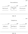
- an embodiment of the present invention further provides a first network device.
- the first network device has a function of implementing an operation of the first network device in the foregoing method example.
- the function may be implemented by hardware or may be implemented by executing corresponding software by hardware.
- the hardware or the software includes one or more modules corresponding to the foregoing function.
- a structure of the first network device includes a receiving unit, a determining unit, and a processing unit. These units can implement corresponding functions in the foregoing method example. For details, refer to detailed descriptions in the method example, and details are not described herein again.
- a structure of the first network device includes a transceiver, a processor, a bus, and a memory.
- the transceiver is configured to communicate and interact with another device in a combined network.
- the processor is configured to support the first network device in performing a corresponding function in the foregoing method.
- the memory is coupled to the processor, and stores a necessary instruction and necessary data for the first network device.
- an embodiment of the present invention further provides a terminal device.
- the terminal device has a function of implementing an operation of the terminal device according to the second aspect in the foregoing method example.
- the function may be implemented by hardware or may be implemented by executing corresponding software by hardware.
- the hardware or the software includes one or more modules corresponding to the foregoing function.
- a structure of the terminal device includes a sending unit, a receiving unit, and a processing unit. These units can implement corresponding functions in the foregoing method example. For details, refer to detailed descriptions in the method example, and details are not described herein again.
- a structure of the terminal device includes a transceiver, a processor, a bus, and a memory.
- the transceiver is configured to communicate and interact with another device in a combined network.
- the processor is configured to support the terminal device in performing a corresponding function in the foregoing method.
- the memory is coupled to the processor, and stores a necessary instruction and necessary data for the terminal device.
- an embodiment of the present invention further provides a terminal device.
- the terminal device has a function of implementing an operation of the terminal device according to the third aspect in the foregoing method example.
- the function may be implemented by hardware or may be implemented by executing corresponding software by hardware.
- the hardware or the software includes one or more modules corresponding to the foregoing function.
- a structure of the terminal device includes a sending unit, a receiving unit, and a processing unit. These units can implement corresponding functions in the foregoing method example. For details, refer to detailed descriptions in the method example, and details are not described herein again.
- a structure of the terminal device includes a transceiver, a processor, a bus, and a memory.
- the transceiver is configured to communicate and interact with another device in a combined network.
- the processor is configured to support the terminal device in performing a corresponding function in the foregoing method.
- the memory is coupled to the processor, and stores a necessary instruction and necessary data for the terminal device.
- the first network device controls the terminal device to stop the establishment of the data connection to the first network, or controls the terminal device to break the data connection to the second network, to smoothly establish the data connection to the first network, thereby ensuring that the terminal device can have a data connection to only one network, ensuring that the terminal device can normally transmit data, implementing network access control on the terminal device, and avoiding occurrence of a network connection error or a runtime error of the terminal device when the terminal device has a data connection to one network and forcibly establishes a data connection to another network.
- Embodiments of this application provide a network access control method and an apparatus, to resolve a prior-art problem that when a terminal device establishes a data connection to one network and forcibly establishes a data connection to another network, occurrence of some network connection errors or a runtime error of the terminal device is caused, and consequently, data cannot be normally transmitted.
- the method and the apparatus in this application are based on a same invention idea.
- the method and the apparatus have similar principles for resolving the problem. Therefore, for implementation of the apparatus and the method, refer to each other, and repeated parts are not described in detail again.
- a first network device determines that a second data connection exists between the terminal device and a second network.
- the first network device may instruct the terminal device to stop the establishment of the first data connection, or instruct the terminal device to end the second data connection and continue to perform a procedure of establishing the first data connection, or the first network device directly ends the second data connection and continues to perform a procedure of establishing the first data connection, or the first network device instructs a second network device to end the second data connection and instructs a third network device to establish the first data connection.
- the first network device controls the terminal device to stop the establishment of the data connection to the first network, or control the terminal device to break the data connection to the second network, to smoothly establish the data connection to the first network, thereby ensuring that the terminal device can have a data connection to only one network, ensuring that the terminal device can normally transmit data, implementing network access control on the terminal device, and avoiding occurrence of a network connection error or a runtime error of the terminal device when the terminal device has a data connection to one network and forcibly establishes a data connection to another network.
- the control plane network element is a network element responsible for mobility management or forwarding path management in a mobile network, for example, control devices such as a mobility management entity (Mobility Management Entity, MME), a serving gateway (Serving Gateway, S-GW), and a packet data network gateway (Packet Data Network Gateway, P-GW), or another control device formed through integration of a plurality of control devices.
- MME mobility management entity
- S-GW serving gateway
- P-GW Packet Data Network Gateway
- a user plane network element is mainly responsible for forwarding a service packet of a terminal device, for example, a physical forwarding plane device such as an S-GW, a P-GW, a router, or a switch, or another virtual forwarding plane network element.
- a physical forwarding plane device such as an S-GW, a P-GW, a router, or a switch, or another virtual forwarding plane network element.
- An access device includes, but is not limited to, an evolved NodeB (evolved Node B, eNB), a radio network controller (radio network controller, RNC), a NodeB (Node B, NB), a base station controller (Base Station Controller, BSC), a base transceiver station (Base Transceiver Station, BTS), a home base station (such as a Home evolved NodeB or a Home Node B, HNB), a baseband unit (BaseBand Unit, BBU), an access point (Access Point, AP), and the like.
- an evolved NodeB evolved Node B
- RNC radio network controller
- NodeB Node B
- BSC Base Station Controller
- BTS Base Transceiver Station
- BTS Base Transceiver Station
- HNB home base station
- BBU baseband unit
- Access Point Access Point
- the terminal device After a terminal device accesses the network by using the access device, the terminal device establishes a data connection to the user plane network element in the network, to transmit user data between the terminal device and the data network; and the terminal device establishes a control connection to the control plane network element in the network, to implement functions such as access management, mobility management, and/or forwarding path management on the terminal device by the control plane network.
- the network access control method provided in the embodiments of this application is applicable to a combined network including a plurality of networks, and in the combined network, a terminal device can access the plurality of networks, but the terminal device cannot simultaneously transmit data by using the plurality of networks.
- the plurality of networks may include any two or more of an LTE network, an SALTE network, a home base station network, a mobile network accessed through Wi-Fi, a GSM network, or a WCDMA network. This is not limited in this application.
- the combined network includes only an LTE network and an SALTE network
- the network access control method provided in the embodiments of this application is not limited to being implemented only in the combined network.
- FIG. 1 shows a possible architecture of a combined network according to an embodiment of this application.
- the combined network includes two networks. A part above a thinner solid line indicates an LTE network, and a part below the solid line indicates an SALTE network.
- the LTE network includes an access device, an S-GW, a P-GW 2, and a data network.
- the access device is configured to connect the terminal device to the LTE network.
- the S-GW is configured to: route and forward a data network in the LTE network, and provide a function related to lawful interception.
- the P-GW 2 is a gateway of the data network, and is an anchor for user data transmission.
- the SALTE network includes a local control plane network element, a local access device, a local gateway, and an internal data network of a local network (namely, On-site Network), and a security node (Security Node), a P-GW 1, and a data network outside the local network.
- a local control plane network element namely, On-site Network
- a local access device namely, On-site Network
- a security node Security Node
- P-GW 1 Packecurity Node
- Each network device in the local network may be a network element device locally deployed by an operator or an enterprise or another third-party authority.
- the local access device is configured to connect the terminal device to the LTE network.
- the local control plane network element is mainly responsible for operations such as access management, session management, and mobility management on the terminal device in the local network.
- the local gateway is configured to transmit user data.
- the security node is configured to establish a secure connection to the terminal device, to ensure that user data is transparent to the local network.
- the P-GW 1 and the P-GW 2 are gateways of the data network in the SALTE network, and are anchors for user data transmission.
- the control plane network element belongs to not only the LTE network but also the SALTE network.
- the control plane network element is mainly responsible for operations such as authentication and service authorization on the terminal device in the combined network.
- the control plane network element may be an MME, or may be a mobile network control plane network element such as an Authentication, Authorization and Accounting (Authentication, Authorization and Accounting, AAA) server.
- AAA Authentication, Authorization and Accounting
- a procedure after the terminal device requests the control plane network element to establish a first data connection to a first network includes the following:
- the control plane network element determines whether a second data connection exists between the terminal device and a second network (a network in the combined network other than the first network).
- control plane network element determines that the second data connection does not exist, the control plane network element directly performs a procedure of establishing the first data connection.
- control plane network element determines that the second data connection exists, the control plane network element controls the terminal device to stop the establishment of the first data connection, or controls the terminal device to break the data connection to the second network, and continues to perform a procedure of establishing the first data connection.
- the control plane network element ensures that the terminal device can have a data connection to only one network, ensures that the terminal device can normally transmit data, implements network access control on the terminal device, and avoids occurrence of a network connection error or a runtime error of the terminal device when the terminal device has a data connection to one network and forcibly establishes a data connection to another network.
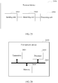
- FIG. 2 shows another possible architecture of a combined network according to an embodiment of this application. Similar to the combined network shown in FIG. 1 , the combined network also includes two networks. Apart above a thinner solid line indicates an LTE network, a part below the solid line indicates an SALTE network, network element devices included in each of the networks are basically the same as network element devices included in a corresponding network in the combined network shown in FIG. 1 , and certainly, functions of the network element devices are also the same. Details are not described herein again.
- the LTE network and the SALTE network no longer share a same control plane network element, and one control plane network element is deployed in each of the SALTE network and the LTE network, namely, a control plane network element 1 and a control plane network element 2 in FIG. 2 .
- the two control plane network elements are responsible for operations such as authentication and service authorization on the terminal device in corresponding networks.
- the control plane network element 1 and the control plane network element 2 in this embodiment of this application may each be a device such as an MME or an AAA server. This is not limited in this application.
- control plane network element 1 and the control plane network element 2 are connected by using a control plane interface, to perform mutual communication.
- a procedure after the terminal device requests the control plane network element 1 in a first network (the LTE network or the SALTE network) to establish a first data connection to the first network (namely, a network access control procedure) includes the following:
- the control plane network element 1 sends a status query request to the control plane network element 2 in a second network (a network in the combined network other than the first network).
- the control plane network element 2 determines whether a second data connection exists between the terminal device and the second network.
- the control plane network element 2 When determining that the second data connection does not exist, the control plane network element 2 returns a first status message to the control plane network element 1, and the control plane network element 1 directly performs a procedure of establishing the first data connection.
- the first status message is used to indicate that the second data connection does not exist between the terminal device and the second network.
- the control plane network element 2 When determining that the second data connection exists, the control plane network element 2 controls the terminal device to break a data connection to the second network, and instructs the control plane network element 1 or the terminal device to continue to perform a procedure of establishing the first data connection; or the control plane network element 2 returns a second status message to the control plane network element 1, so that the control plane network element 1 controls, based on the second status message, the terminal device to stop the establishment of the first data connection or controls the terminal device to end the second data connection, and continues to perform a procedure of establishing the first data connection.
- the second status message is used to indicate that the second data connection exists between the terminal device and the second network.
- control plane network element 1 and/or the control plane network element 2 can ensure that the terminal device can have a data connection to only one network, ensure that the terminal device can normally transmit data, implement network access control on the terminal device, and avoid occurrence of a network connection error or a runtime error of the terminal device when the terminal device has a data connection to one network and forcibly establishes a data connection to another network.
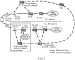
- FIG. 3 shows still another possible architecture of a combined network according to an embodiment of this application. Similar to the combined network shown in FIG. 2 , the combined network also includes two networks. Apart above a thinner solid line indicates an LTE network, a part below the solid line indicates an SALTE network, network element devices included in each of the networks are basically the same as network element devices included in a corresponding network in the combined network shown in FIG. 2 , and certainly, functions of the network element devices are also the same. Details are not described herein again.
- control plane network element 1 and the control plane network element 2 are not connected by using a control plane interface, but are connected to a same HSS, and communication between the control plane network element 1 and the control plane network element 2 is implemented by using the HSS.
- the architecture of the combined network including the LTE network and the SALTE network is not limited to the three architectures shown in FIG. 1 to FIG. 3 . Because there may be a relatively large quantity of possible architectures, only the foregoing three architectures are used as examples in the embodiments of this application.
- the control plane network element in either of the networks can check a status of a data connection between the terminal device and the network; in addition, after determining the status of the data connection between the terminal device and the network, the control plane network element in the network may further send the status to the HSS in the combined network. Therefore, the HSS may also check the status of the data connection between the terminal device and the network.
- a procedure after the terminal device requests the control plane network element 1 in a first network (the LTE network or the SALTE network) to establish a first data connection to the first network (namely, a network access control procedure) may also be classified into two types:
- a first type If the control plane network element 2 in the second network (a network in the combined network other than the first network) checks a status of a second data connection between the terminal device and the second network, the procedure is similar to a specific procedure in the combined network shown in FIG. 2 .
- the HSS needs to serve as an intermediate node. Therefore, for the procedure, refer to the specific procedure in the combined network shown in FIG. 2 , and details are not described herein again.
- a second type If the HSS in the combined network checks a status of a second data connection between the terminal device and the second network, the procedure includes the following: The control plane network element 1 sends a status query request to the HSS.
- the HSS determines whether the second data connection exists between the terminal device and the second network.
- the HSS When determining that the second data connection does not exist, the HSS returns a first status message to the control plane network element 1, and the control plane network element 1 directly performs a procedure of establishing the first data connection.
- the first status message is used to indicate that the second data connection does not exist between the terminal device and the second network.
- the HSS controls the terminal device or controls the control plane network element 2 to break the data connection to the second network, and instructs the control plane network element 1 or the terminal device to continue to perform a procedure of establishing the first data connection; or the HSS returns a second status message to the control plane network element 1, so that the control plane network element 1 controls, based on the second status message, the terminal device to stop the establishment of the first data connection or controls the terminal device to end the second data connection, and continues to perform a procedure of establishing the first data connection.
- the second status message is used to indicate that the second data connection exists between the terminal device and the second network.
- the HSS and/or the control plane network element 1 can ensure that the terminal device can have a data connection to only one network, ensure that the terminal device can normally transmit data, implement network access control on the terminal device, and avoid occurrence of a network connection error or a runtime error of the terminal device when the terminal device has a data connection to one network and forcibly establishes a data connection to another network.
- a specific operation of requesting, by the terminal device, to establish the first data connection to the first network is as follows:
- the terminal device sends a data connection request for the first network to the control plane network element 1 (or the control plane network element in the combined network shown in FIG. 1 ) in the first network.
- the data connection request may be control plane signaling such as an attach request (Attach Request).
- the first network device namely, the control plane network element or the HSS
- the first network device in the combined network can control the terminal device to stop the establishment of the data connection to the first network, or control the terminal device to break the data connection to the second network, to smoothly establish the data connection to the first network, thereby ensuring that the terminal device can have a data connection to only one network, ensuring that the terminal device can normally transmit data, implementing network access control on the terminal device, and avoiding occurrence of a network connection error or a runtime error of the terminal device when the terminal device has a data connection to one network and forcibly establishes a data connection to another network.
- An embodiment of this application provides a network access control method.
- the method is applicable to various combined networks, and may be used in, but not limited to, the combined network shown in FIG. 1 , FIG. 2 , or FIG. 3 .
- a specific procedure of the method includes the following steps.
- Step 401 A first network device determines, after a terminal device requests to establish a first data connection to a first network, that a second data connection exists between the terminal device and a second network.
- the first network is any network, for example, an SALTE network or an LTE network, in the combined network
- the second network is a network in the combined network other than the first network.
- the first network device is a network device in the combined network, and may include a control plane network element or an HSS.
- the control plane network element may be a network device deployed in the first network, for example, the control plane network element 1 in the combined network shown in FIG. 2 or FIG. 3 ; or may be a network element device deployed in the second network, for example, the control plane network element 2 in the combined network shown in FIG. 2 or FIG. 3 ; or may be a network device shared in the first network and the second network, for example, the control plane network element in the combined network shown in FIG. 1 .
- the method before the determining, by a first network device, that a second data connection exists between the terminal device and the second network, the method further includes:
- the determining, by a first network device, that the second data connection exists between the terminal device and the second network includes:
- the terminal device when the second network is an LTE network, after the terminal device accesses the LTE network, the terminal device has two states in the second network: an idle (idle) state and a connected (connect) state.
- an idle (idle) state When the terminal device is in the connected state, a data connection exists between the terminal device and the LTE network.
- the terminal device When the terminal device is in the idle state, no data connection exists, but only a control connection exists between the terminal device and the LTE network. Therefore, the terminal device can transmit user data to the LTE network only when the terminal is in the connected state in the LTE network.
- the determining, by a first network device, that the second data connection exists between the terminal device and the second network includes: determining, by the first network device, that the terminal device is in a connected state in the second network.
- the first network determines that the terminal device is in the connected state in the second network, to determine that the second data connection exists.
- Step 402 The first network device performs any one of the following operations:
- the method includes: sending, by the first network device, an access stop message to the terminal device, where the access stop message is used to instruct the terminal device to stop the establishment of the first data connection.
- the first network device controls the terminal device to stop the establishment of the first data connection to the first network, thereby ensuring that the terminal device can have a data connection to only one network, ensuring that the terminal device can normally transmit data, implementing network access control on the terminal device, and avoiding occurrence of a network connection error or a runtime error of the terminal device when the terminal device has a data connection to one network and forcibly establishes a data connection to another network.
- the access stop message includes a status error cause, and the status error cause is used to notify that the second data connection exists between the terminal device and the second network.
- the first network device can notify the terminal device of a reason for stopping the establishment of the first data connection.
- the sending, by the first network device, the access stop message to the terminal device includes: forwarding, by the first network device, the access stop message to the terminal device by using another network device.
- the control plane network element 2 forwards the access stop message to the terminal device by using the control plane network element 1.
- the control plane network element 2 forwards the access stop message to the terminal device by using the HSS and the control plane network element 1.
- the HSS forwards the access stop message to the terminal device by using the control plane network element 1.
- the first network device can smoothly send the access stop message to the terminal device.
- the instructing, by the first network device, the terminal device to end the second data connection includes: sending, by the first network device, a first switching request message to the terminal device, where the first switching request message is used to instruct the terminal device to switch a data connection of the terminal device from the second data connection to the first data connection.
- the first network device controls the terminal device to switch the second data connection to the first data connection, to smoothly establish the first data connection, thereby ensuring that the terminal device can have a data connection to only one network, ensuring that the terminal device can normally transmit data, implementing network access control on the terminal device, and avoiding occurrence of a network connection error or a runtime error of the terminal device when the terminal device has a data connection to one network and forcibly establishes a data connection to another network.
- the first switching request message includes a status error cause, and the status error cause is used to notify that the second data connection exists between the terminal device and the second network.
- the first network device can notify the terminal device of a reason for switching the second data connection.
- the sending, by the first network device, a first switching request message to the terminal device includes: forwarding, by the first network device, the first switching request message to the terminal device by using another network device.
- the control plane network element 2 forwards the first switching request message to the terminal device by using the control plane network element 1.
- the control plane network element 2 forwards the first switching request message to the terminal device by using the HSS and the control plane network element 1.
- the HSS forwards the first switching request message to the terminal device by using the control plane network element 1.
- the first network device can smoothly send the first switching request message to the terminal device.
- the first network device ends the second data connection in the following two manners:
- the first network device directly ends the second data connection, to smoothly establish the first data connection, thereby ensuring that the terminal device can have a data connection to only one network, ensuring that the terminal device can normally transmit data, implementing network access control on the terminal device, and avoiding occurrence of a network connection error or a runtime error of the terminal device when the terminal device has a data connection to one network and forcibly establishes a data connection to another network.
- the first network device continues to perform the procedure of establishing the first data connection.
- the first network device performs a procedure of configuring the terminal device and a user plane network element in the first network device, and the like, to ensure user data transmission between the terminal device and the first network.
- the instructing, by the first network device, the second network device to end the second data connection includes: sending, by the first network device, a second switching request message to the second network device, where the second switching request message is used to instruct the second network device to switch a data connection of the terminal device from the second data connection to the first data connection.
- the control plane network element 2 sends the second switching request message to the control plane network element 1.
- the control plane network element 2 sends the second switching request message to the control plane network element 1 by using the HSS.
- the HSS sends the second switching request message to the control plane network element 1.
- the first network device controls the second network device to end the second data connection, to smoothly establish the first data connection, thereby ensuring that the terminal device can have a data connection to only one network, ensuring that the terminal device can normally transmit data, implementing network access control on the terminal device, and avoiding occurrence of a network connection error or a runtime error of the terminal device when the terminal device has a data connection to one network and forcibly establishes a data connection to another network.
- the second switching request message includes a status error cause
- the status error cause is used to notify the second network device that the second data connection exists between the terminal device and the second network.
- the first network device can notify the second network device of a reason for switching the data connection of the terminal device.
- the network access control method provided in this embodiment of this application further includes: after the terminal device requests to establish the first data connection to the first network, determining, by the first network device, that no data connection exists between the terminal device and the second network; and performing, by the first network device, the procedure of establishing the first data connection.
- the first network device may directly perform, by using a conventional data connection establishment method, the procedure of establishing the first data connection.
- the determining, by the first network device, that no data connection exists between the terminal device and the second network includes: determining, by the first network device, that the terminal device is in an idle state in the second network.
- the first network device determines that the terminal device is in the idle state in the second network, and determines that no data connection exists between the terminal device and the second network.
- the first network device controls the terminal device to stop the establishment of the first data connection to the first network, or controls the terminal device to end the second data connection to the second network, to smoothly establish the first data connection to the first network, thereby ensuring that the terminal device can have a data connection to only one network, ensuring that the terminal device can normally transmit data, implementing network access control on the terminal device, and avoiding occurrence of a network connection error or a runtime error of the terminal device when the terminal device has a data connection to one network and forcibly establishes a data connection to another network.
- an embodiment of this application further provides a network access control method.
- the method is applicable to various combined networks, and may be used in, but not limited to, the combined network shown in FIG. 1 , FIG. 2 , or FIG. 3 .
- a specific procedure of the method includes the following steps.
- Step 501 After a terminal device requests to establish a first data connection to a first network, the terminal device receives an access stop message sent by a first network device, where the access stop message is used to instruct the terminal device to stop the establishment of the first data connection.
- the access stop message includes a status error cause, and the status error cause is used to notify that the second data connection exists between the terminal device and the second network.
- the receiving, by the terminal device, the access stop message sent by the first network device includes: receiving, by the terminal device by using another network device, the access stop message sent by the first network device.
- the terminal device receives, by using the control plane network element 1, the access stop message sent by the control plane network element 2.
- the terminal device receives, by using the control plane network element 1 and the HSS, the access stop message sent by the control plane network element 2.
- the terminal device receives, by using the control plane network element 1, the access stop message sent by the HSS.
- the terminal device can smoothly receive the access stop message sent by the first network device.
- the terminal device requests, in the following two manners, to establish the first data connection to the first network:
- Step 502 The terminal device stops a procedure of establishing the first data connection.
- the terminal device receives the access stop message sent by the first network device, and stops the procedure of establishing the first data connection, to avoid occurrence of a network connection error or a runtime error of the terminal device when a data connection is forcibly established to the first network.
- an embodiment of this application further provides a network access control method.
- the method is applicable to various combined networks, and may be used in, but not limited to, the combined network shown in FIG. 1 , FIG. 2 , or FIG. 3 .
- a specific procedure of the method includes the following steps.
- Step 601 After a terminal device requests to establish a first data connection to a first network, the terminal device receives a first switching request message sent by a first network device, where the first switching request message is used to instruct the terminal device to switch a data connection of the terminal device from a second data connection to the first data connection, and the second data connection is a data connection existing between the terminal device and a second network.
- the first switching request message includes a status error cause, and the status error cause is used to notify that the second data connection exists between the terminal device and the second network.
- the receiving, by the terminal device, the first switching request message sent by the first network device includes: receiving, by the terminal device by using another network device, the first switching request message sent by the first network device.
- the terminal device receives, by using the control plane network element 1, the first switching request message sent by the control plane network element 2.
- the terminal device receives, by using the HSS and the control plane network element 1, the first switching request message sent by the control plane network element 2.
- the terminal device receives, by using the control plane network element 1, the first switching request message forwarded by the HSS.
- the terminal device can smoothly receive the first switching request message sent by the first network device.
- the terminal device requests, in the following two manners, to establish the first data connection to the first network:
- Step 602 The terminal device switches the data connection of the terminal device from the second data connection to the first data connection.
- the terminal device after the terminal device requests to establish the first data connection to the first network, the terminal device receives a first switching access message sent by the first network device, and switches the data connection of the terminal device from the second data connection to the first data connection, to avoid occurrence of a network connection error or a runtime error of the terminal device when a data connection is forcibly established to the first network if the second data connection is not broken.
- network access scenarios of the terminal device are classified into two types: In a first network access scenario, the terminal device requests to establish a data connection to the LTE network; and in a second network access scenario, the terminal device requests to establish a data connection to the SALTE network.
- a first network access scenario the terminal device requests to establish a data connection to the LTE network
- a second network access scenario the terminal device requests to establish a data connection to the SALTE network.
- only the second network access scenario is used as an example for description.
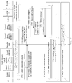
- Example 1 In the architecture of the combined network shown in FIG. 1 , referring to FIG. 7 , a specific procedure of an example of the network access control method includes the following steps.
- Step 701 UE sends a data connection request to the local control plane network element, where the data connection request carries an SALTE access indication (SALTE Transition Indication) and a UE identifier (Identifier, ID).
- SALTE access indication SALTE Transition Indication
- ID UE identifier
- the SALTE transition indication is used to indicate that the UE already accesses the LTE network, and now a DC mode is started to access the SALTE network.
- the UE ID may be a globally unique temporary UE identity (Globally Unique Temporary UE Identity, GUTI).
- GUTI Globally Unique Temporary UE Identity
- Step 702 The local control plane network element sends the data connection request to the control plane network element.
- Step 703 After receiving the data connection request, the control plane network element checks a status of the UE corresponding to the UE ID in the LTE network according to the SALTE transition indication.
- Step 704 and step 705 The control plane network element sends a connection refused response (also referred to as an access stop message) to the UE by using the local control plane network element, where the connection refused response may include a status error cause (Status error).
- a connection refused response also referred to as an access stop message
- the connection refused response may include a status error cause (Status error).
- the UE After receiving the connection refused response, the UE stops a procedure of accessing the SALTE network.
- Step 706 The control plane network element continues a procedure of accessing the SALTE network.
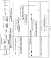
- Example 2 In the architecture of the combined network shown in FIG. 1 , referring to FIG. 8 , a specific procedure of an example of the network access control method includes the following steps.
- Step 801 to step 803 are the same as step 701 to step 703 in Example 1, and step 808 when the UE is in a non-connected state is also the same as step 706 in Example 1. Details are not described herein again.
- a difference from Example 1 lies in that, steps performed when the UE is in a connected state are different.
- Step 804-805 The control plane network element sends a switching request message to the UE by using the local control plane network element.
- the switching request message may include a status error cause.
- Step 806 After receiving the switching request message, the UE initiates a data connection switching procedure.
- the switching procedure is as follows: The UE switches a data connection of the UE from a data connection between the UE and the LTE network to a data connection between the UE and the SALTE network.
- Step 807 The control plane network element continues a procedure of accessing the SALTE network.
- Example 3 In the architecture of the combined network shown in FIG. 1 , referring to FIG. 9 , a specific procedure of an example of the network access control method includes the following steps.
- Step 901 to 903 are the same as step 701 to step 703 in Example 1, and step 906 when the UE is in a non-connected state is also the same as step 706 in Example 1. Details are not described herein again.
- a difference from Example 1 lies in that, steps performed when the UE is in a connected state are different.
- Step 904 The control plane network element initiates a switching process, to switch a data connection of the UE from a data connection between the UE and the LTE network to a data connection between the UE and the SALTE network.
- Step 905 The control plane network element continues a procedure of accessing the SALTE network.
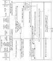
- Example 4 In the architecture of the combined network shown in FIG. 1 , referring to FIG. 10 , a specific procedure of an example of the network access control method includes the following steps.
- Step 1001 to step 1003 are the same as step 701 to step 703 in Example 1, and step 1006 when the UE is in a non-connected state is also the same as step 706 in Example 1. Details are not described herein again.
- a difference from Example 1 lies in that, steps performed when the UE is in a connected state are different.
- Step 1004 The control plane network element initiates an S1-release procedure, so that the status of the UE in the LTE network changes to the non-connected state.
- Step 1005 The control plane network element continues a procedure of accessing the SALTE network.
- Example 5 In the architecture of the combined network shown in 2, referring to FIG. 11 , a specific procedure of an example of the network access control method includes the following steps.
- Step 1101 UE sends a data connection request to the local control plane network element, where the data connection request carries an SALTE access indication and a UE ID.
- the SALTE access indication is used to indicate that the UE already accesses the LTE network, and now a DC mode is started to access the SALTE network.
- the UE ID may be a globally unique temporary UE identity (Globally Unique Temporary UE Identity, GUTI).
- GUTI Globally Unique Temporary UE Identity
- Step 1102 The local control plane network element sends the data connection request to the control plane network element 1 in the SALTE network.
- Step 1103 After receiving the data connection request, the control plane network element 1 sends a status query request to the control plane network element 2 in the LTE network according to the SALTE transition indication.
- the status query request is used to instruct the control plane network element 2 to check a status of the UE in the LTE network.
- the status query request includes the UE ID.
- Step 1104 The control plane network element 2 checks a status of the UE, to determine the status of the UE in the LTE network.
- Step 1105 The control plane network element 2 sends a status message to the control plane network element 1.
- the status message is used to notify the control plane network element 1 of the status of the UE in the LTE network.
- Step 1106 and step 1107 The control plane network element 1 sends a connection refused response (also referred to as an access stop message) to the UE by using the local control plane network element, where the connection refused response may include a status error cause.
- a connection refused response also referred to as an access stop message
- the UE After receiving the connection refused response, the UE stops a procedure of accessing the SALTE network.
- Step 1108 The control plane network element 1 continues a procedure of accessing the SALTE network.
- Example 6 In the architecture of the combined network shown in 2, referring to FIG. 12 , a specific procedure of an example of the network access control method includes the following steps.
- Step 1201 to step 1204 are the same as step 1101 to step 1104 in Example 5, and step 1210 when the UE is in a non-connected state is also the same as step 1108 in Example 5. Details are not described herein again.
- Step 1105 After determining the status of the UE in the LTE network, send a status message to the control plane network element 1, and further, when determining that the UE is in a connected state in the LTE network, directly send a switching request indication (also referred to as a second switching request message in the foregoing embodiment) to the control plane network element 1.
- a switching request indication also referred to as a second switching request message in the foregoing embodiment
- the status message is used to notify the control plane network element 1 of the status of the UE in the LTE network.
- the second switching request message is used to instruct the control plane network element 1 to switch a data connection of the terminal device from the second data connection to the first data connection.
- Step 1206 and step 1207 When receiving the status message indicating that the UE is in the connected state or when receiving the switching request indication, the control plane network element 1 sends a switching request message (also referred to as a first switching request message in the foregoing embodiment) to the UE by using the local control plane network element.
- a switching request message also referred to as a first switching request message in the foregoing embodiment
- the switching request message may include a status error cause.
- Step 1208 The UE initiates a data connection switching procedure after receiving the switching request message.
- the switching procedure is as follows: The UE switches a data connection of the UE from a data connection between the UE and the LTE network to a data connection between the UE and the SALTE network.
- step 1209 The control plane network element 1 continues a procedure of accessing the SALTE network.
- Example 7 In the architecture of the combined network shown in 2, referring to FIG. 13 , a specific procedure of an example of the network access control method includes the following steps.
- Step 1301 to step 1305 are the same as step 1201 to step 1205 in Example 6, and step 1308 when the UE is in a non-connected state is also the same as step 1210 in Example 6. Details are not described herein again.
- a difference from Example 6 lies in that, steps performed when the UE is in a connected state are different.
- Step 1306 When receiving the status message indicating that the UE is in the connected state or when receiving the switching request indication, the control plane network element 1 initiates a switching process, to switch a data connection of the UE from a data connection between the UE and the LTE network to a data connection between the UE and the SALTE network.
- Step 1307 The control plane network element continues a procedure of accessing an SALTE network.
- Example 8 In the architecture of the combined network shown in 2, referring to FIG. 14 , a specific procedure of an example of the network access control method includes the following steps.
- Step 1401 to step 1404 are the same as step 1101 to step 1104 in Example 5. Details are not described herein again.
- a difference from Example 5 lies in that: Steps performed when the UE is in a connected state are different.
- Step 1405 The control plane network element 2 determines that the UE is in the connected state in the LTE network, and the control plane network element initiates an S1-release procedure, so that the status of the UE in the LTE network changes to a non-connected state (an idle state).
- Step 1406 The control plane network element 2 sends a status message of the UE at this time to the control plane network element 1, where the status message is used to notify the control plane network element 1 that the UE is in the non-connected state in the LTE network at this time.
- Step 1407 The control plane network element 1 continues a procedure of accessing the SALTE network.
- Steps performed when the UE is in the connected state are different.
- Step 1408 and step 1409 are the same as step 1406 and step 1407. Details are not described herein again
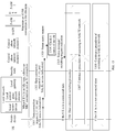
- Example 9 In the architecture of the combined network shown in FIG. 3 , referring to FIG. 15 , a specific procedure of an example of the network access control method includes the following steps.
- Step 1501 UE sends a local connection request to the local access device, the local control plane network element, and the local gateway in the local network.
- Step 1502 The UE sends a data connection request to the security node based on the Internet Key Exchange Version 2 (Internet Key Exchange v2, IKEv2) protocol by using the local access device, where the data connection request carries an SALTE access indication and a UE ID.
- Internet Key Exchange Version 2 Internet Key Exchange v2, IKEv2
- the SALTE access indication is used to indicate that the UE already accesses the LTE network, and now a DC mode is started to access the SALTE network.
- the UE ID may be a globally unique temporary UE identity (Globally Unique Temporary UE Identity, GUTI).
- GUTI Globally Unique Temporary UE Identity
- Step 1503 The security node sends the data connection request to the control plane network element 1 in the SALTE network.
- Step 1504 and step 1505 After receiving the data connection request, the control plane network element 1 sends a status query request to the control plane network element 2 in the LTE network according to the SALTE transition indication by using the HSS.
- the status query request is used to instruct the control plane network element 2 to check a status of the UE in the LTE network.
- the status query request includes the UE ID.
- Step 1506 The control plane network element 2 checks a status of the UE, to determine the status of the UE in the LTE network.
- Step 1507 and step 1508 The control plane network element 2 sends a status message to the control plane network element 1 by using the HSS.
- the status message is used to notify the control plane network element 1 of the status of the UE in the LTE network.
- Step 1509 and 1510 The control plane network element 1 sends a connection refused response (also referred to as an access stop message) to the UE by using the security node, where the connection refused response may include a status error cause.
- a connection refused response also referred to as an access stop message
- the UE After receiving the connection refused response, the UE stops a procedure of accessing the SALTE network.
- Step 1511 The control plane network element 1 continues a procedure of accessing the SALTE network.
- Example 10 In the architecture of the combined network shown in FIG. 3 , referring to FIG. 16 , a specific procedure of an example of the network access control method includes the following steps.
- Step 1601 to step 1608 are the same as step 1501 to step 1508 in Example 9. Details are not described herein again.
- step 1609 to step 1613 are the same as step 1206 to step 1210 in Example 6. Details are not described herein again.
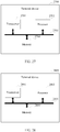
- Example 11 In the architecture of the combined network shown in FIG. 3 , referring to FIG. 17 , a specific procedure of an example of the network access control method includes the following steps.
- Step 1701 to step 1708 are the same as step 1501 to step 1508 in Example 9. Details are not described herein again.
- step 1709 to step 1711 are the same as step 1306 to step 1308 in Example 7. Details are not described herein again.
- Example 12 In the architecture of the combined network shown in FIG. 3 , referring to FIG. 18 , a specific procedure of an example of the network access control method includes the following steps.
- Step 1801 to step 1806 are the same as step 1501 to step 1506 in Example 9. Details are not described herein again.
- step 1807 to step 1811 are the same as step 1405 to step 1409 in Example 8. Details are not described herein again.
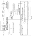
- Example 13 In the architecture of the combined network shown in FIG. 3 , referring to FIG. 19 , a specific procedure of an example of the network access control method includes the following steps.
- Step 1900 When a status of UE in the LTE network changes, the control plane network element 2 in the LTE network sends a status notification to the HSS, to notify the HSS of the status of the UE in the LTE network.
- Step 1901 The UE sends a local connection request to the local access device, the local control plane network element, and the local gateway in the local network.
- Step 1902 The UE sends a data connection request to the security node according to the IKEv2 protocol by using the local access device, where the data connection request carries an SALTE access indication and a UE ID.
- the SALTE access indication is used to indicate that the UE already accesses the LTE network, and now a DC mode is started to access the SALTE network.
- the UE ID may be a GUTI.
- Step 1903 The security node sends the data connection request to the control plane network element 1 in the SALTE network.
- Step 1904 After receiving the data connection request, the control plane network element 1 sends a status query request to the HSS according to the SALTE access indication.
- the status query request is used to instruct the HSS to check a status of the UE in the LTE network.
- the status query request includes the UE ID.
- Step 1905 The HSS checks a status of the UE, to determine the status of the UE in the LTE network.
- Step 1906 The HSS sends a status message to the control plane network element 1.
- the status message is used to notify the control plane network element 1 of the status of the UE in the LTE network.
- step 1907 to step 1909 are the same as step 1509 to step 1511 in Example 15. Details are not described herein again.
- Example 14 In the architecture of the combined network shown in FIG. 3 , referring to FIG. 20 , a specific procedure of an example of the network access control method includes the following steps.
- Step 2000 to step 2006 are the same as step 1900 to step 1906 in Example 13. Details are not described herein again.
- Step 2007 to step 2011 are the same as step 1609 to step 1613 in Example 10. Details are not described herein again.
- Example 15 In the architecture of the combined network shown in FIG. 3 , referring to FIG. 21 , a specific procedure of an example of the network access control method includes the following steps.
- Step 2100 to step 2106 are the same as step 1900 to 1906 in Example 13. Details are not described herein again.
- Step 2107 to step 2109 are the same as step 1709 to 1711 in Example 11. Details are not described herein again.
- Example 16 In the architecture of the combined network shown in FIG. 3 , referring to FIG. 22 , a specific procedure of an example of the network access control method includes the following steps.
- Step 2200 to step 2205 are the same as step 1900 to step 1905 in Example 13. Details are not described herein again.
- Steps performed when the UE is in a connected state include:
- Steps performed when the UE is in the non-connected state include:
- any one of the examples of the network access control method in the embodiments of this application it can be ensured that the terminal device can have a data connection to only one network, it can be ensured that the terminal device can normally transmit data, network access control can be implemented on the terminal device, and occurrence of a network connection error or a runtime error of the terminal device when the terminal device has a data connection to one network and forcibly establishes a data connection to another network can be avoided.
- this application further provides a first network device.
- the first network device is applied to any one of the combined networks shown in FIG. 1 to FIG. 3 , and is configured to implement the network access control method shown in FIG. 4 .
- the first network device 2300 includes a determining unit 2301 and a processing unit 2302.
- the determining unit 2301 is configured to determine, after a terminal device requests to establish a first data connection to a first network, that a second data connection exists between the terminal device and a second network.
- the processing unit 2302 is configured to perform the following operation:
- the first network device 2300 further includes: a receiving unit 2303, configured to: before the determining unit 2301 determines that the second data connection exists between the terminal device and the second network, receive a data connection request for the first network sent by the terminal device; or receive a status query request sent by a fourth network device.
- a receiving unit 2303 configured to: before the determining unit 2301 determines that the second data connection exists between the terminal device and the second network, receive a data connection request for the first network sent by the terminal device; or receive a status query request sent by a fourth network device.
- the determining unit 2301 when determining that the second data connection exists between the terminal device and the second network, is specifically configured to:
- the determining unit 2301 when determining that the second data connection exists between the terminal device and the second network, is specifically configured to: determine that the terminal device is in a connected state in the second network.
- the processing unit 2302 when instructing the terminal device to stop the establishment of the first data connection, is specifically configured to: send an access stop message to the terminal device, where the access stop message is used to instruct the terminal device to stop the establishment of the first data connection.
- the access stop message includes a status error cause, and the status error cause is used to notify that the second data connection exists between the terminal device and the second network.
- the processing unit 2302 when sending the access stop message to the terminal device, is specifically configured to: forward the access stop message to the terminal device by using another network device.
- the processing unit 2302 when instructing the terminal device to end the second data connection, is specifically configured to: send a first switching request message to the terminal device, where the first switching request message is used to instruct the terminal device to switch a data connection of the terminal device from the second data connection to the first data connection.
- the first switching request message includes a status error cause, and the status error cause is used to notify that the second data connection exists between the terminal device and the second network.
- the processing unit 2302 when sending the first switching request message to the terminal device, is specifically configured to: forward the first switching request message to the terminal device by using another network device.
- the processing unit 2302 when breaking the second data connection, is specifically configured to:
- the processing unit 2302 when instructing the second network device to end the second data connection, is specifically configured to: send a second switching request message to the second network device, where the second switching request message is used to instruct the second network device to switch a data connection of the terminal device from the second data connection to the first data connection.
- the second switching request message includes a status error cause
- the status error cause is used to notify the second network device that the second data connection exists between the terminal device and the second network.
- the determining unit 2301 is further configured to determine that no data connection exists between the terminal device and the second network; and the processing unit 2302 is further configured to perform the procedure of establishing the first data connection.
- the determining unit 2301 when determining that no data connection exists between the terminal device and the second network, is specifically configured to: determine that the terminal device is in an idle state in the second network.
- the first network device 2300 includes a control plane network element or an HSS.
- the first network device controls the terminal device to stop the establishment of the first data connection to the first network, or controls the terminal device to end the second data connection to the second network, to smoothly establish the first data connection to the first network, thereby ensuring that the terminal device can have a data connection to only one network, ensuring that the terminal device can normally transmit data, implementing network access control on the terminal device, and avoiding occurrence of a network connection error or a runtime error of the terminal device when the terminal device has a data connection to one network and forcibly establishes a data connection to another network.
- this application further provides a terminal device.
- the terminal device is applied to any one of the combined networks shown in FIG. 1 to FIG. 3 , and is configured to implement the network access control method shown in FIG. 5 .
- the terminal device 2400 includes a sending unit 2401, a receiving unit 2402, and a processing unit 2403.
- the sending unit 2401 is configured to request to establish a first data connection to a first network.
- the receiving unit 2402 is configured to receive an access stop message sent by a first network device, where the access stop message is used to instruct the terminal device to stop the establishment of the first data connection.
- the processing unit 2403 is configured to stop a procedure of establishing the first data connection.
- the access message includes a status error cause, and the status error cause is used to notify that the second data connection exists between the terminal device 2400 and the second network.
- the receiving unit 2402 when receiving the access stop message sent by the first network device, is specifically configured to: receive, by using another network device, the access stop message sent by the first network device.
- the sending unit 2401 when requesting to establish the first data connection to the first network, is specifically configured to:
- the terminal device after the terminal device requests to establish the first data connection to the first network, the terminal device receives the access stop message sent by the first network device, and stops the procedure of establishing the first data connection, to avoid occurrence of a network connection error or a runtime error of the terminal device when a data connection is forcibly established to the first network.
- this application further provides a terminal device.
- the terminal device is applied to any one of the combined networks shown in FIG. 1 to FIG. 3 , and is configured to implement the network access control method shown in FIG. 6 .
- the terminal device 2500 includes a sending unit 2501, a receiving unit 2502, and a processing unit 2503.
- the sending unit 2501 is configured to request to establish a first data connection to a first network.
- the receiving unit 2502 is configured to receive a first switching request message sent by a first network device, where the first switching request message is used to instruct the terminal device to switch a data connection of the terminal device from a second data connection to the first data connection, and the second data connection is a data connection existing between the terminal device and a second network.
- the processing unit 2503 is configured to switch the data connection of the terminal device from the second data connection to the first data connection.
- the first switching request message includes a status error cause, and the status error cause is used to notify that the second data connection exists between the terminal device 2500 and the second network.
- the receiving unit 2502 when receiving the first switching request message sent by the first network device, is specifically configured to: receive, by using another network device, the first switching request message sent by the first network device.
- the sending unit 2501 when requesting to establish the first data connection to the first network, is specifically configured to:
- the terminal device after the terminal device requests to establish the first data connection to the first network, the terminal device receives a first switching access message sent by the first network device, and switches the data connection of the terminal device from the second data connection to the first data connection, to avoid occurrence of a network connection error or a runtime error of the terminal device when a data connection is forcibly established to the first network if the second data connection is not broken.
- the unit division in the embodiments of this application is an example and is merely logical function division. During actual implementation, there may be another division manner.
- Functional units in the embodiments of this application may be integrated into one processing unit, or each of the units may exist alone physically, or two or more units are integrated into one unit.
- the integrated unit may be implemented in a form of hardware, or may be implemented in a form of a software functional unit.
- the integrated unit When the integrated unit is implemented in the form of a software functional unit and sold or used as an independent product, the integrated unit may be stored in a computer-readable storage medium. Based on such an understanding, the technical solutions of this application essentially, or the part contributing to the prior art, or all or some of the technical solutions may be implemented in the form of a software product.
- the computer software product is stored in a storage medium and includes several instructions for instructing a computer device (which may be a personal computer, a server, a network device, or the like) or a processor (processor) to perform all or some of the steps of the methods described in the embodiments of this application.
- the foregoing storage medium includes: any medium that can store program code, such as a USB flash drive, a removable hard disk, a read-only memory (ROM, Read-Only Memory), a random access memory (RAM, Random Access Memory), a magnetic disk, or an optical disc.
- program code such as a USB flash drive, a removable hard disk, a read-only memory (ROM, Read-Only Memory), a random access memory (RAM, Random Access Memory), a magnetic disk, or an optical disc.
- an embodiment of this application further provides a first network device.
- the first network device is applied to any one of the combined networks shown in FIG. 1 to FIG. 3 , and is configured to implement the network access control method shown in FIG. 4 .
- the first network device includes a control plane network element or an HSS.
- the first network device 2600 includes a transceiver 2601, a processor 2602, a bus 2603, and a memory 2604.
- the transceiver 2601, the processor 2602, and the memory 2604 are connected to each other by using the bus 2603.
- the bus 2603 may be a peripheral component interconnect (peripheral component interconnect, PCI for short) bus or an extended industry standard architecture (extended industry standard architecture, EISA for short) bus, or the like.
- the bus may be classified into an address bus, a data bus, a control bus, and the like. For ease of representation, only one thick line is used to represent the bus in FIG. 26 , but this does not mean that there is only one bus or only one type of bus.
- the transceiver 2601 is configured to communicate and interact with another device that is in the combined network and that is connected to the first network device.
- the processor 2602 is configured to implement the network access control method shown in FIG. 4 , including: determining, after a terminal device requests to establish a first data connection to a first network, that a second data connection exists between the terminal device and a second network; and performing the following operation:
- the processor 2602 is further configured to: before determining that the second data connection exists between the terminal device and the second network, receive a data connection request for the first network sent by the terminal device; or receive a status query request sent by a fourth network device.
- the processor 2602 when determining that the second data connection exists between the terminal device and the second network, is specifically configured to: detect that the second data connection exists between the terminal device and the second network; or receive a status message sent by a fifth network device, and determine, based on the status message, that the second data connection exists between the terminal device and the second network, where the status message is used to indicate that the second data connection exists between the terminal device and the second network.
- the processor 2602 when determining that the second data connection exists between the terminal device and the second network, is specifically configured to: determine that the terminal device is in a connected state in the second network.
- the processor 2602 when instructing the terminal device to stop the establishment of the first data connection, is specifically configured to: send an access stop message to the terminal device, where the access stop message is used to instruct the terminal device to stop the establishment of the first data connection.
- the access stop message includes a status error cause, and the status error cause is used to notify that the second data connection exists between the terminal device and the second network.
- the processor 2602 when sending the access stop message to the terminal device, is specifically configured to: forward the access stop message to the terminal device by using another network device.
- the processor 2602 when instructing the terminal device to end the second data connection, is specifically configured to: send a first switching request message to the terminal device, where the first switching request message is used to instruct the terminal device to switch a data connection of the terminal device from the second data connection to the first data connection.
- the first switching request message includes a status error cause, and the status error cause is used to notify that the second data connection exists between the terminal device and the second network.
- the processor 2602 when sending the first switching request message to the terminal device, is specifically configured to: forward the first switching request message to the terminal device by using another network device.
- the processor 2602 when breaking the second data connection, is specifically configured to:
- the processor 2602 when instructing the second network device to end the second data connection, is specifically configured to: send a second switching request message to the second network device, where the second switching request message is used to instruct the second network device to switch a data connection of the terminal device from the second data connection to the first data connection.
- the second switching request message includes a status error cause
- the status error cause is used to notify the second network device that the second data connection exists between the terminal device and the second network.
- the processor 2602 is further configured to determine that no data connection exists between the terminal device and the second network; and perform the procedure of establishing the first data connection.
- the processor 2602 when determining that no data connection exists between the terminal device and the second network, is specifically configured to: determine that the terminal device is in an idle state in the second network.
- the memory 2604 is configured to store a program and the like.
- the program may include program code.
- the program code includes a computer operation instruction.
- the memory 2604 may include a random access memory (random access memory, RAM for short), and may also include a non-volatile memory (non-volatile memory), for example, at least one magnetic disk memory.
- the processor 2602 executes an application program stored in the memory 2604 to implement the foregoing function, thereby implementing the network access control method shown in FIG. 4 .
- the first network device controls the terminal device to stop the establishment of the first data connection to the first network, or controls the terminal device to end the second data connection to the second network, to smoothly establish the first data connection to the first network, thereby ensuring that the terminal device can have a data connection to only one network, ensuring that the terminal device can normally transmit data, implementing network access control on the terminal device, and avoiding occurrence of a network connection error or a runtime error of the terminal device when the terminal device has a data connection to one network and forcibly establishes a data connection to another network.
- this application further provides a terminal device.
- the terminal device is applied to any one of the combined networks shown in FIG. 1 to FIG. 3 , and is configured to implement the network access control method shown in FIG. 5 .
- the terminal device 2700 includes a transceiver 2701, a processor 2702, a bus 2703, and a memory 2704.
- the transceiver 2701, the processor 2702, and the memory 2704 are connected to each other by using the bus 2703.
- the bus 2703 may be a PCI bus, an EISA bus, or the like.
- the bus may be classified into an address bus, a data bus, a control bus, and the like. For ease of representation, only one thick line is used to represent the bus in FIG. 27 , but this does not mean that there is only one bus or only one type of bus.
- the transceiver 2701 is configured to communicate and interact with another device that is in the combined network and that is connected to the terminal device.
- the processor 2702 is configured to implement the network access control method shown in FIG. 5 , including:
- the access message includes a status error cause, and the status error cause is used to notify that the second data connection exists between the terminal device 2700 and the second network.
- the processor 2702 when receiving the access stop message sent by the first network device, is specifically configured to: receive, by using another network device, the access stop message sent by the first network device.
- the processor 2702 when requesting to establish the first data connection to the first network, is specifically configured to:
- the memory 2704 is configured to store a program and the like.
- the program may include program code.
- the program code includes a computer operation instruction.
- the memory 2704 may include a random access memory (random access memory, RAM for short), and may also include a non-volatile memory (non-volatile memory), for example, at least one magnetic disk memory.
- the processor 2702 executes an application program stored in the memory 2704 to implement the foregoing function, thereby implementing the network access control method shown in FIG. 5 .
- the terminal device after the terminal device requests to establish the first data connection to the first network, the terminal device receives the access stop message sent by the first network device, and stops the procedure of establishing the first data connection, to avoid occurrence of a network connection error or a runtime error of the terminal device when a data connection is forcibly established to the first network.
- this application further provides a terminal device.
- the terminal device is applied to any one of the combined networks shown in FIG. 1 to FIG. 3 , and is configured to implement the network access control method shown in FIG. 6 .
- the terminal device 2800 includes a transceiver 2801, a processor 2802, a bus 2803, and a memory 2804.
- the transceiver 2801, the processor 2802, and the memory 2804 are connected to each other by using the bus 2803.
- the bus 2803 may be a PCI bus, an EISA bus, or the like.
- the bus may be classified into an address bus, a data bus, a control bus, and the like. For ease of representation, only one thick line is used to represent the bus in FIG. 28 , but this does not mean that there is only one bus or only one type of bus.
- the transceiver 2801 is configured to communicate and interact with another device that is in the combined network and that is connected to the first network device.
- the processor 2802 is configured to implement the network access control method shown in FIG. 6 , including:
- the first switching request message includes a status error cause
- the status error cause is used to notify that the second data connection exists between the terminal device 2800 and the second network.
- the processor 2802 when receiving the first switching request message sent by the first network device, is specifically configured to: receive, by using another network device, the first switching request message sent by the first network device.
- the processor 2802 when requesting to establish the first data connection to the first network, is specifically configured to:
- the memory 2804 is configured to store a program and the like.
- the program may include program code.
- the program code includes a computer operation instruction.
- the memory 2804 may include a RAM, and may also include a non-volatile memory, for example, at least one magnetic disk memory.
- the processor 2802 executes an application program stored in the memory 2804 to implement the foregoing function, thereby implementing the network access control method shown in FIG. 6 .
- the terminal device after the terminal device requests to establish the first data connection to the first network, the terminal device receives a first switching access message sent by the first network device, and switches the data connection of the terminal device from the second data connection to the first data connection, to avoid occurrence of a network connection error or a runtime error of the terminal device when a data connection is forcibly established to the first network if the second data connection is not broken.
- the embodiments of this application provide the network access control method and the apparatus.
- the first network device determines that the second data connection exists between the terminal device and the second network.
- the first network device may instruct the terminal device to stop the establishment of the first data connection, or instruct the terminal device to end the second data connection and continue to perform the procedure of establishing the first data connection, or the first network device directly ends the second data connection and continues to perform a procedure of establishing the first data connection, or the first network device instructs the second network device to end the second data connection and instructs the third network device to establish the first data connection.
- the first network device controls the terminal device to stop the establishment of the data connection to the first network, or control the terminal device to break the data connection to the second network, to smoothly establish the data connection to the first network, thereby ensuring that the terminal device can have a data connection to only one network, ensuring that the terminal device can normally transmit data, implementing network access control on the terminal device, and avoiding occurrence of a network connection error or a runtime error of the terminal device when the terminal device has a data connection to one network and forcibly establishes a data connection to another network.
- this application may be provided as a method, a system, or a computer program product. Therefore, this application may use a form of hardware only embodiments, software only embodiments, or embodiments with a combination of software and hardware. Moreover, this application may use a form of a computer program product that is implemented on one or more computer-usable storage media (including, but not limited to, a magnetic disk memory, a CD-ROM, an optical memory, and the like) that include computer usable program code.
- computer-usable storage media including, but not limited to, a magnetic disk memory, a CD-ROM, an optical memory, and the like
- These computer program instructions may be provided for a general-purpose computer, a dedicated computer, an embedded processor, or a processor of any other programmable data processing device to generate a machine, so that the instructions executed by a computer or a processor of any other programmable data processing device generate an apparatus for implementing a specific function in one or more processes in the flowcharts and/or in one or more blocks in the block diagrams.
- These computer program instructions may be stored in a computer readable memory that can instruct the computer or any other programmable data processing device to work in a specific manner, so that the instructions stored in the computer readable memory generate an artifact that includes an instruction apparatus.
- the instruction apparatus implements a specific function in one or more processes in the flowcharts and/or in one or more blocks in the block diagrams.
- These computer program instructions may be loaded onto a computer or another programmable data processing device, so that a series of operations and steps are performed on the computer or the another programmable device, thereby generating computer-implemented processing. Therefore, the instructions executed on the computer or the another programmable device provide steps for implementing a specific function in one or more processes in the flowcharts and/or in one or more blocks in the block diagrams.
Abstract
Description
- This application relates to the field of communications technologies, and in particular, to a network access control method and an apparatus.
- At present, with development of communications technologies, many terminal devices support access to a plurality of networks of different types. In some cases, even if a terminal device accesses a plurality of networks, the terminal device cannot transmit data in parallel by using two or more networks. To be specific, when the terminal device transmits data by using one network (where the terminal device establishes a data connection to the network), a data connection between the terminal device and another network needs to be ended. For example, the terminal device is in an idle state in the another network.
- If a terminal device can access a plurality of networks but cannot transmit data in parallel by using the plurality of networks, when the terminal device establishes a data connection to one network, and forcibly establishes a data connection to another network, some network connection errors or runtime errors of the terminal device occur. Consequently, data cannot be normally transmitted.
- For example, a terminal device in dual connectivity (Dual Connectivity, DC) mode can access both a second access Long Term Evolution (Second Access Long Term Evolution, SALTE) network and a Long Term Evolution (Long Term Evolution, LTE) network. The terminal device can access the SALTE network only when the terminal device does not access the LTE network or the terminal device is in an idle state in the LTE network. If the terminal device forcibly accesses the SALTE network when the terminal device is in a connected state in the LTE network, a network connection error or a runtime error of the terminal device occurs.
- Embodiments of this application provide a network access control method and an apparatus, to resolve a prior-art problem that when a terminal device establishes a data connection to one network and forcibly establishes a data connection to another network, occurrence of some network connection errors or a runtime error of the terminal device is caused, and consequently, data cannot be normally transmitted.
- Specific technical solutions provided in the embodiments of this application are as follows:
According to a first aspect, an embodiment of this application provides a network access control method, including: - determining, by a first network device after a terminal device requests to establish a first data connection to a first network, that a second data connection exists between the terminal device and a second network; and performing any one of the following operations after the determining is completed:
- a first operation: instructing, by the first network device, the terminal device to stop the establishment of the first data connection;
- a second operation: instructing, by the first network device, the terminal device to end the second data connection, or after the first network device ends the second data connection, continuing, by the first network device, to perform a procedure of establishing the first data connection; or
- a third operation: instructing, by the first network device, a second network device to end the second data connection, and instructing a third network device to establish the first data connection.
- According to the foregoing method, if the terminal device already establishes the second data connection to the second network, the first network device controls the terminal device to stop the establishment of the first data connection to the first network, or controls the terminal device to end the second data connection to the second network, to smoothly establish the first data connection to the first network, thereby ensuring that the terminal device can have a data connection to only one network, ensuring that the terminal device can normally transmit data, implementing network access control on the terminal device, and avoiding occurrence of a network connection error or a runtime error of the terminal device when the terminal device has a data connection to one network and forcibly establishes a data connection to another network.
- In a possible design, before the determining, by a first network device, that a second data connection exists between the terminal device and the second network, the first network device receives a data connection request for the first network sent by the terminal device; or the first network device receives a status query request sent by a fourth network device. The status query request is used to instruct the first network device to determine a status of the second data connection of the terminal device.
- In a possible design, the first network device determines, in the following two manners, that the second data connection exists between the terminal device and the second network, where the two manners include:
- a first manner: when the first network device is notified after the status of the second data connection of the terminal device is updated, detecting, by the first network device, that the second data connection exists between the terminal device and the second network; and
- a second manner: when the first network device cannot directly determine the status of the second data connection, receiving, by the first network device, a status message sent by a fifth network device, and determining, based on the status message, that the second data connection exists between the terminal device and the second network, where the status message is used to indicate that the second data connection exists between the terminal device and the second network.
- According to the foregoing method, the first network device can determine that the second data connection exists between the terminal device and the second network.
- In a possible design, the first network device may determine that the terminal device is in a connected state in the second network, to determine that the second data connection exists between the terminal device and the second network. For example, when the second network is an LTE network, the first network device may determine, according to the method, that the second data connection exists between the terminal device and the second network.
- According to the foregoing method, the first network determines that the terminal device is in the connected state in the second network, to determine that the second data connection exists.
- In a possible design, the instructing, by the first network device, the terminal device to stop the establishment of the first data connection includes:
sending, by the first network device, an access stop message to the terminal device, where the access stop message is used to instruct the terminal device to stop the establishment of the first data connection. - According to the foregoing method, if the terminal device already establishes the second data connection to the second network, the first network device controls the terminal device to stop the establishment of the first data connection to the first network, thereby ensuring that the terminal device can have a data connection to only one network, ensuring that the terminal device can normally transmit data, implementing network access control on the terminal device, and avoiding occurrence of a network connection error or a runtime error of the terminal device when the terminal device has a data connection to one network and forcibly establishes a data connection to another network.
- In a possible design, the access stop message includes a status error cause, and the status error cause is used to notify that the second data connection exists between the terminal device and the second network.
- According to the foregoing method, the first network device can notify the terminal device of a reason for stopping the establishment of the first data connection.
- In a possible design, the first network device forwards the access stop message to the terminal device by using another network device. The another network device may be a device such as an HSS or a control plane network element.
- According to the foregoing method, the first network device can smoothly send the access stop message to the terminal device.
- In a possible design, the instructing, by the first network device, the terminal device to end the second data connection includes:
sending, by the first network device, a first switching request message to the terminal device, where the first switching request message is used to instruct the terminal device to switch a data connection of the terminal device from the second data connection to the first data connection. - According to the foregoing method, if the terminal device already establishes the second data connection to the second network, the first network device controls the terminal device to switch the second data connection to the first data connection, to smoothly establish the first data connection, thereby ensuring that the terminal device can have a data connection to only one network, ensuring that the terminal device can normally transmit data, implementing network access control on the terminal device, and avoiding occurrence of a network connection error or a runtime error of the terminal device when the terminal device has a data connection to one network and forcibly establishes a data connection to another network.
- In a possible design, the first switching request message includes a status error cause, and the status error cause is used to notify that the second data connection exists between the terminal device and the second network.
- According to the foregoing method, the first network device can notify the terminal device of a reason for switching the second data connection.
- In a possible design, the first network device forwards the first switching request message to the terminal device by using another network device. The another network device may be a device such as an HSS or a control plane network element.
- According to the foregoing method, the first network device can smoothly send the first switching request message to the terminal device.
- In a possible design, the first network device ends the second data connection in the following two manners:
- a first manner: the first network device initiates a release procedure of the second data connection, for example, the first network device initiates an S I-release (S1-release) procedure; and
- a second manner: the first network device switches a data connection of the terminal device from the second data connection to the first data connection.
- According to the foregoing method, if the terminal device already establishes the second data connection to the second network, the first network device directly ends the second data connection, to smoothly establish the first data connection, thereby ensuring that the terminal device can have a data connection to only one network, ensuring that the terminal device can normally transmit data, implementing network access control on the terminal device, and avoiding occurrence of a network connection error or a runtime error of the terminal device when the terminal device has a data connection to one network and forcibly establishes a data connection to another network.
- In a possible design, the instructing, by the first network device, the second network device to end the second data connection includes:
sending, by the first network device, a second switching request message to the second network device, where the second switching request message is used to instruct the second network device to switch a data connection of the terminal device from the second data connection to the first data connection. - According to the foregoing method, if the terminal device already establishes the second data connection to the second network, the first network device controls the second network device to end the second data connection, to smoothly establish the first data connection, thereby ensuring that the terminal device can have a data connection to only one network, ensuring that the terminal device can normally transmit data, implementing network access control on the terminal device, and avoiding occurrence of a network connection error or a runtime error of the terminal device when the terminal device has a data connection to one network and forcibly establishes a data connection to another network.
- In a possible design, the second switching request message includes a status error cause, and the status error cause is used to notify the second network device that the second data connection exists between the terminal device and the second network.
- According to the foregoing method, the first network device can notify the second network device of a reason for switching the data connection of the terminal device.
- In a possible design, the first network device determines that no data connection exists between the terminal device and the second network; and
the first network device performs a procedure of establishing the first data connection. - In a possible design, the first network device determines that the terminal device is in an idle state in the second network, to determine that no data connection exists between the terminal device and the second network. For example, if the second network is an LTE network, according to the foregoing method, it can be determined that no data connection exists between the terminal device and the second network.
- According to the foregoing method, the first network device determines that the terminal device is in the idle state in the second network, and determines that no data connection exists between the terminal device and the second network.
- In a possible design, the first network device includes a control plane network element or a home subscriber server HSS.
- According to a second aspect, an embodiment of this application provides a network access control method, including:
after a terminal device requests to establish a first data connection to a first network, when the terminal device receives an access stop message sent by a first network device, stopping, by the terminal device, a procedure of establishing the first data connection, where the access stop message is used to instruct the terminal device to stop the establishment of the first data connection. - According to the foregoing method, after the terminal device requests to establish the first data connection to the first network, the terminal device receives the access stop message sent by the first network device, and stops the procedure of establishing the first data connection, to avoid occurrence of a network connection error or a runtime error of the terminal device when a data connection is forcibly established to the first network.
- In a possible design, the access stop message includes a status error cause, and the status error cause is used to notify that the second data connection exists between the terminal device and the second network.
- In a possible design, the terminal device receives, by using another network device, the access stop message sent by the first network device. The another network device may be a device such as an HSS or a control plane network element.
- According to the foregoing method, the terminal device can smoothly receive the access stop message sent by the first network device.
- In a possible design, the terminal device requests, in the following two manners, to establish the first data connection to the first network:
- a first manner: the terminal device sends a data connection request for the first network to the first network device; and
- a second manner: the terminal device sends a data connection request for the first network to the another network device.
- According to a third aspect, an embodiment of this application provides a network access control method, including:
after a terminal device requests to establish a first data connection to a first network, when the terminal device receives a first switching request message sent by a first network device, switching, by the terminal device, a data connection of the terminal device from a second data connection to the first data connection, where the second data connection is a data connection existing between the terminal device and a second network, and the first switching request message is used to instruct the terminal device to switch the data connection of the terminal device from the second data connection to the first data connection. - According to the foregoing method, after the terminal device requests to establish the first data connection to the first network, the terminal device receives a first switching access message sent by the first network device, and switches the data connection of the terminal device from the second data connection to the first data connection, to avoid occurrence of a network connection error or a runtime error of the terminal device when a data connection is forcibly established to the first network if the second data connection is not broken.
- In a possible design, the first switching request message includes a status error cause, and the status error cause is used to notify that the second data connection exists between the terminal device and the second network.
- In a possible design, the terminal device receives, by using another network device, the first switching request message sent by the first network device. The another network device may be a device such as an HSS or a control plane network element.
- According to the foregoing method, the terminal device can smoothly receive the first switching request message sent by the first network device.
- In a possible design, the terminal device requests, in the following two manners, to establish the first data connection to the first network:
- a first manner: the terminal device sends a data connection request for the first network to the first network device; and
- a second manner: the terminal device sends a data connection request for the first network to the another network device.
- According to a fourth aspect, an embodiment of the present invention further provides a first network device. The first network device has a function of implementing an operation of the first network device in the foregoing method example. The function may be implemented by hardware or may be implemented by executing corresponding software by hardware. The hardware or the software includes one or more modules corresponding to the foregoing function.
- In a possible design, a structure of the first network device includes a receiving unit, a determining unit, and a processing unit. These units can implement corresponding functions in the foregoing method example. For details, refer to detailed descriptions in the method example, and details are not described herein again.
- In a possible design, a structure of the first network device includes a transceiver, a processor, a bus, and a memory. The transceiver is configured to communicate and interact with another device in a combined network. The processor is configured to support the first network device in performing a corresponding function in the foregoing method. The memory is coupled to the processor, and stores a necessary instruction and necessary data for the first network device.
- According to a fifth aspect, an embodiment of the present invention further provides a terminal device. The terminal device has a function of implementing an operation of the terminal device according to the second aspect in the foregoing method example. The function may be implemented by hardware or may be implemented by executing corresponding software by hardware. The hardware or the software includes one or more modules corresponding to the foregoing function.
- In a possible design, a structure of the terminal device includes a sending unit, a receiving unit, and a processing unit. These units can implement corresponding functions in the foregoing method example. For details, refer to detailed descriptions in the method example, and details are not described herein again.
- In a possible design, a structure of the terminal device includes a transceiver, a processor, a bus, and a memory. The transceiver is configured to communicate and interact with another device in a combined network. The processor is configured to support the terminal device in performing a corresponding function in the foregoing method. The memory is coupled to the processor, and stores a necessary instruction and necessary data for the terminal device.
- According to a sixth aspect, an embodiment of the present invention further provides a terminal device. The terminal device has a function of implementing an operation of the terminal device according to the third aspect in the foregoing method example. The function may be implemented by hardware or may be implemented by executing corresponding software by hardware. The hardware or the software includes one or more modules corresponding to the foregoing function.
- In a possible design, a structure of the terminal device includes a sending unit, a receiving unit, and a processing unit. These units can implement corresponding functions in the foregoing method example. For details, refer to detailed descriptions in the method example, and details are not described herein again.
- In a possible design, a structure of the terminal device includes a transceiver, a processor, a bus, and a memory. The transceiver is configured to communicate and interact with another device in a combined network. The processor is configured to support the terminal device in performing a corresponding function in the foregoing method. The memory is coupled to the processor, and stores a necessary instruction and necessary data for the terminal device.
- According to the network access control method provided in the embodiments of this application, if the terminal device already establishes the data connection to the second network, the first network device controls the terminal device to stop the establishment of the data connection to the first network, or controls the terminal device to break the data connection to the second network, to smoothly establish the data connection to the first network, thereby ensuring that the terminal device can have a data connection to only one network, ensuring that the terminal device can normally transmit data, implementing network access control on the terminal device, and avoiding occurrence of a network connection error or a runtime error of the terminal device when the terminal device has a data connection to one network and forcibly establishes a data connection to another network.
-
-
FIG. 1 is a first schematic architectural diagram of a combined network according to an embodiment of this application; -
FIG. 2 is a second schematic architectural diagram of a combined network according to an embodiment of this application; -
FIG. 3 is a third schematic architectural diagram of a combined network according to an embodiment of this application; -
FIG. 4 shows a network access control method according to an embodiment of this application; -
FIG. 5 shows another network access control method according to an embodiment of this application; -
FIG. 6 shows still another network access control method according to an embodiment of this application; -
FIG. 7 is a first flowchart of an example of a network access control method according to an embodiment of this application; -
FIG. 8 is a second flowchart of an example of a network access control method according to an embodiment of this application; -
FIG. 9 is a third flowchart of an example of a network access control method according to an embodiment of this application; -
FIG. 10 is a fourth flowchart of an example of a network access control method according to an embodiment of this application; -
FIG. 11 is a fifth flowchart of an example of a network access control method according to an embodiment of this application; -
FIG. 12 is a sixth flowchart of an example of a network access control method according to an embodiment of this application; -
FIG. 13 is a seventh flowchart of an example of a network access control method according to an embodiment of this application; -
FIG. 14 is an eighth flowchart of an example of a network access control method according to an embodiment of this application; -
FIG. 15 is a ninth flowchart of an example of a network access control method according to an embodiment of this application; -
FIG. 16 is a tenth flowchart of an example of a network access control method according to an embodiment of this application; -
FIG. 17 is an eleventh flowchart of an example of a network access control method according to an embodiment of this application; -
FIG. 18 is a twelfth flowchart of an example of a network access control method according to an embodiment of this application; -
FIG. 19 is a thirteenth flowchart of an example of a network access control method according to an embodiment of this application; -
FIG. 20 is a fourteenth flowchart of an example of a network access control method according to an embodiment of this application; -
FIG. 21 is a fifteenth flowchart of an example of a network access control method according to an embodiment of this application; -
FIG. 22 is a sixteenth flowchart of an example of a network access control method according to an embodiment of this application; -
FIG. 23 is a schematic structural diagram of a first network device according to an embodiment of this application; -
FIG. 24 is a schematic structural diagram of a terminal device according to an embodiment of this application; -
FIG. 25 is a schematic structural diagram of another terminal device according to an embodiment of this application; -
FIG. 26 is a structural diagram of a first network device according to an embodiment of this application; -
FIG. 27 is a structural diagram of a terminal device according to an embodiment of this application; and -
FIG. 28 is a structural diagram of another terminal device according to an embodiment of this application. - To make the objectives, technical solutions, and advantages of this application clearer, the following further describes this application in detail with reference to the accompanying drawings. Apparently, the described embodiments are merely some rather than all of the embodiments of this application. All other embodiments obtained by persons of ordinary skill in the art based on the embodiments of this application without creative efforts shall fall within the protection scope of this application.
- Embodiments of this application provide a network access control method and an apparatus, to resolve a prior-art problem that when a terminal device establishes a data connection to one network and forcibly establishes a data connection to another network, occurrence of some network connection errors or a runtime error of the terminal device is caused, and consequently, data cannot be normally transmitted. The method and the apparatus in this application are based on a same invention idea. The method and the apparatus have similar principles for resolving the problem. Therefore, for implementation of the apparatus and the method, refer to each other, and repeated parts are not described in detail again.
- In the embodiments of this application, after a terminal device requests to establish a first data connection to a first network, a first network device determines that a second data connection exists between the terminal device and a second network. In this case, the first network device may instruct the terminal device to stop the establishment of the first data connection, or instruct the terminal device to end the second data connection and continue to perform a procedure of establishing the first data connection, or the first network device directly ends the second data connection and continues to perform a procedure of establishing the first data connection, or the first network device instructs a second network device to end the second data connection and instructs a third network device to establish the first data connection. In conclusion, if the terminal device already establishes the data connection to the second network, the first network device controls the terminal device to stop the establishment of the data connection to the first network, or control the terminal device to break the data connection to the second network, to smoothly establish the data connection to the first network, thereby ensuring that the terminal device can have a data connection to only one network, ensuring that the terminal device can normally transmit data, implementing network access control on the terminal device, and avoiding occurrence of a network connection error or a runtime error of the terminal device when the terminal device has a data connection to one network and forcibly establishes a data connection to another network.
- In the following, some terms in this application are explained and described, to help persons skilled in the art have a better understanding.
- (1) A network in the embodiments of this application includes an access device, a user plane (User Plane, UP) network element, a control plane (Control Plane, CP) network element, and a data network (Data Network, DN). For example, the network may be an LTE network, an SALTE network, a home base station network, another non-3rd Generation Partnership Project (3rd Generation Partnership Project, 3GPP) mobile network (such as a mobile network accessed through Wireless Fidelity (Wireless-Fidelity, Wi-Fi)), a Global System for Mobile Communications (Global System for Mobile Communication, GSM) network, a Wideband Code Division Multiple Access (Wideband Code Division Multiple Access, WCDMA) network, or a future network. This is not limited in this application.
- The control plane network element is a network element responsible for mobility management or forwarding path management in a mobile network, for example, control devices such as a mobility management entity (Mobility Management Entity, MME), a serving gateway (Serving Gateway, S-GW), and a packet data network gateway (Packet Data Network Gateway, P-GW), or another control device formed through integration of a plurality of control devices.
- A user plane network element is mainly responsible for forwarding a service packet of a terminal device, for example, a physical forwarding plane device such as an S-GW, a P-GW, a router, or a switch, or another virtual forwarding plane network element.
- An access device includes, but is not limited to, an evolved NodeB (evolved Node B, eNB), a radio network controller (radio network controller, RNC), a NodeB (Node B, NB), a base station controller (Base Station Controller, BSC), a base transceiver station (Base Transceiver Station, BTS), a home base station (such as a Home evolved NodeB or a Home Node B, HNB), a baseband unit (BaseBand Unit, BBU), an access point (Access Point, AP), and the like.
- After a terminal device accesses the network by using the access device, the terminal device establishes a data connection to the user plane network element in the network, to transmit user data between the terminal device and the data network; and the terminal device establishes a control connection to the control plane network element in the network, to implement functions such as access management, mobility management, and/or forwarding path management on the terminal device by the control plane network.
- (2) An SALTE network in this application is a mobile network deployed by an operator or an enterprise. In the SALTE network, a terminal device may access an internal data network of the operator or the enterprise, or may access an external data network (to be specific, access a packet data network (Packet Data Network, PDN) connection).
- (3) A terminal device in this application, also referred to as user equipment (User Equipment, UE), is a data connectivity device, for example, a handheld device having a wireless connection function, an in-vehicle device, a wearable device, a computing device, a mobile station (Mobile Station, MS), another processing device connected to a wireless modem, or a mobile terminal communicating with one or more core networks by using a radio access network.
- (4) A data connection in this application is a connection by using which user data can be directly transmitted. When the terminal device is in a connected state in a network, a data connection exists between the terminal device and the network.
- (5) A network device in this application may be a control plane network element or a user plane network element or another device in a network, for example, a home subscriber server (Home Subscriber Service, HSS). A "first network device" in this application is a network device in a network that can implement network access control on a terminal device. In addition, each of a "second network device", a "third network device", and "another network device" in this application is a network device other than the first network device in the network. In a same embodiment, any two of the "second network device", the "third network device", and the "another network device" may be a same network device or different network devices. This is not limited in this application.
- (6) "A plurality of' mentioned in the embodiments of this application means two or more.
- The term "and/or" mentioned in the descriptions of this application describes an association relationship between associated objects and represents that three relationships may exist. For example, A and/or B may represent the following three cases: Only A exists, both A and B exist, and only B exists. The character "/" generally indicates an "or" relationship between the associated objects.
- In addition, it should be understood that, in the descriptions of this application, the terms such as "first" and "second" are only used for the purpose of distinguishing and description, but cannot be understood as an indication or implication of relative importance, and cannot be understood as an indication or implication of a sequence.
- The network access control method provided in the embodiments of this application is applicable to a combined network including a plurality of networks, and in the combined network, a terminal device can access the plurality of networks, but the terminal device cannot simultaneously transmit data by using the plurality of networks. The plurality of networks may include any two or more of an LTE network, an SALTE network, a home base station network, a mobile network accessed through Wi-Fi, a GSM network, or a WCDMA network. This is not limited in this application.
- In the embodiments of this application, an example in which the combined network includes only an LTE network and an SALTE network is used for description, but the network access control method provided in the embodiments of this application is not limited to being implemented only in the combined network.
- To more clearly describe a technical method in the embodiments of this application, possible architectures of a combined network in the embodiments of this application are described below with reference to
FIG. 1 to FIG. 3 . -
FIG. 1 shows a possible architecture of a combined network according to an embodiment of this application. The combined network, as shown in the figure, includes two networks. A part above a thinner solid line indicates an LTE network, and a part below the solid line indicates an SALTE network. - The LTE network includes an access device, an S-GW, a P-
GW 2, and a data network. - The access device is configured to connect the terminal device to the LTE network.
- The S-GW is configured to: route and forward a data network in the LTE network, and provide a function related to lawful interception.
- The P-
GW 2 is a gateway of the data network, and is an anchor for user data transmission. - The SALTE network includes a local control plane network element, a local access device, a local gateway, and an internal data network of a local network (namely, On-site Network), and a security node (Security Node), a P-
GW 1, and a data network outside the local network. Each network device in the local network may be a network element device locally deployed by an operator or an enterprise or another third-party authority. - The local access device is configured to connect the terminal device to the LTE network.
- The local control plane network element is mainly responsible for operations such as access management, session management, and mobility management on the terminal device in the local network.
- The local gateway is configured to transmit user data.
- The security node is configured to establish a secure connection to the terminal device, to ensure that user data is transparent to the local network.
- The P-
GW 1 and the P-GW 2 are gateways of the data network in the SALTE network, and are anchors for user data transmission. - In the combined network, the LTE network and the SALTE network share a control plane network. Therefore, the control plane network element belongs to not only the LTE network but also the SALTE network. The control plane network element is mainly responsible for operations such as authentication and service authorization on the terminal device in the combined network. For example, the control plane network element may be an MME, or may be a mobile network control plane network element such as an Authentication, Authorization and Accounting (Authentication, Authorization and Accounting, AAA) server.
- In the combined network shown in
FIG. 1 , a procedure after the terminal device requests the control plane network element to establish a first data connection to a first network (the LTE network or the SALTE network) (namely, a network access control procedure) includes the following:
The control plane network element determines whether a second data connection exists between the terminal device and a second network (a network in the combined network other than the first network). - When the control plane network element determines that the second data connection does not exist, the control plane network element directly performs a procedure of establishing the first data connection.
- When the control plane network element determines that the second data connection exists, the control plane network element controls the terminal device to stop the establishment of the first data connection, or controls the terminal device to break the data connection to the second network, and continues to perform a procedure of establishing the first data connection.
- According to the foregoing procedure, the control plane network element ensures that the terminal device can have a data connection to only one network, ensures that the terminal device can normally transmit data, implements network access control on the terminal device, and avoids occurrence of a network connection error or a runtime error of the terminal device when the terminal device has a data connection to one network and forcibly establishes a data connection to another network.
-
FIG. 2 shows another possible architecture of a combined network according to an embodiment of this application. Similar to the combined network shown inFIG. 1 , the combined network also includes two networks. Apart above a thinner solid line indicates an LTE network, a part below the solid line indicates an SALTE network, network element devices included in each of the networks are basically the same as network element devices included in a corresponding network in the combined network shown inFIG. 1 , and certainly, functions of the network element devices are also the same. Details are not described herein again. - The only difference from the combined network shown in
FIG. 1 lies in that, the LTE network and the SALTE network no longer share a same control plane network element, and one control plane network element is deployed in each of the SALTE network and the LTE network, namely, a controlplane network element 1 and a controlplane network element 2 inFIG. 2 . The two control plane network elements are responsible for operations such as authentication and service authorization on the terminal device in corresponding networks. Similar to the control plane network element inFIG. 1 , the controlplane network element 1 and the controlplane network element 2 in this embodiment of this application may each be a device such as an MME or an AAA server. This is not limited in this application. - The control
plane network element 1 and the controlplane network element 2 are connected by using a control plane interface, to perform mutual communication. - In the combined network shown in
FIG. 2 , a procedure after the terminal device requests the controlplane network element 1 in a first network (the LTE network or the SALTE network) to establish a first data connection to the first network (namely, a network access control procedure) includes the following:
The controlplane network element 1 sends a status query request to the controlplane network element 2 in a second network (a network in the combined network other than the first network). - The control
plane network element 2 determines whether a second data connection exists between the terminal device and the second network. - When determining that the second data connection does not exist, the control
plane network element 2 returns a first status message to the controlplane network element 1, and the controlplane network element 1 directly performs a procedure of establishing the first data connection. The first status message is used to indicate that the second data connection does not exist between the terminal device and the second network. - When determining that the second data connection exists, the control
plane network element 2 controls the terminal device to break a data connection to the second network, and instructs the controlplane network element 1 or the terminal device to continue to perform a procedure of establishing the first data connection; or the controlplane network element 2 returns a second status message to the controlplane network element 1, so that the controlplane network element 1 controls, based on the second status message, the terminal device to stop the establishment of the first data connection or controls the terminal device to end the second data connection, and continues to perform a procedure of establishing the first data connection. The second status message is used to indicate that the second data connection exists between the terminal device and the second network. - According to the foregoing procedure, the control
plane network element 1 and/or the controlplane network element 2 can ensure that the terminal device can have a data connection to only one network, ensure that the terminal device can normally transmit data, implement network access control on the terminal device, and avoid occurrence of a network connection error or a runtime error of the terminal device when the terminal device has a data connection to one network and forcibly establishes a data connection to another network. -
FIG. 3 shows still another possible architecture of a combined network according to an embodiment of this application. Similar to the combined network shown inFIG. 2 , the combined network also includes two networks. Apart above a thinner solid line indicates an LTE network, a part below the solid line indicates an SALTE network, network element devices included in each of the networks are basically the same as network element devices included in a corresponding network in the combined network shown inFIG. 2 , and certainly, functions of the network element devices are also the same. Details are not described herein again. - The only difference from the combined network shown in
FIG. 2 lies in that, the controlplane network element 1 and the controlplane network element 2 are not connected by using a control plane interface, but are connected to a same HSS, and communication between the controlplane network element 1 and the controlplane network element 2 is implemented by using the HSS. - In an actual scenario, the architecture of the combined network including the LTE network and the SALTE network is not limited to the three architectures shown in
FIG. 1 to FIG. 3 . Because there may be a relatively large quantity of possible architectures, only the foregoing three architectures are used as examples in the embodiments of this application. - In the combined network shown in
FIG. 2 , the control plane network element in either of the networks can check a status of a data connection between the terminal device and the network; in addition, after determining the status of the data connection between the terminal device and the network, the control plane network element in the network may further send the status to the HSS in the combined network. Therefore, the HSS may also check the status of the data connection between the terminal device and the network. - In the combined network shown in
FIG. 3 , based on different manners of determining the terminal device and a second network, a procedure after the terminal device requests the controlplane network element 1 in a first network (the LTE network or the SALTE network) to establish a first data connection to the first network (namely, a network access control procedure) may also be classified into two types:
A first type: If the controlplane network element 2 in the second network (a network in the combined network other than the first network) checks a status of a second data connection between the terminal device and the second network, the procedure is similar to a specific procedure in the combined network shown inFIG. 2 . For communication and interaction between the controlplane network element 1 and the controlplane network element 2, the HSS needs to serve as an intermediate node. Therefore, for the procedure, refer to the specific procedure in the combined network shown inFIG. 2 , and details are not described herein again. - A second type: If the HSS in the combined network checks a status of a second data connection between the terminal device and the second network, the procedure includes the following:
The controlplane network element 1 sends a status query request to the HSS. - The HSS determines whether the second data connection exists between the terminal device and the second network.
- When determining that the second data connection does not exist, the HSS returns a first status message to the control
plane network element 1, and the controlplane network element 1 directly performs a procedure of establishing the first data connection. The first status message is used to indicate that the second data connection does not exist between the terminal device and the second network. - When determining that the second data connection exists, the HSS controls the terminal device or controls the control
plane network element 2 to break the data connection to the second network, and instructs the controlplane network element 1 or the terminal device to continue to perform a procedure of establishing the first data connection; or the HSS returns a second status message to the controlplane network element 1, so that the controlplane network element 1 controls, based on the second status message, the terminal device to stop the establishment of the first data connection or controls the terminal device to end the second data connection, and continues to perform a procedure of establishing the first data connection. The second status message is used to indicate that the second data connection exists between the terminal device and the second network. - According to the foregoing procedure, the HSS and/or the control
plane network element 1 can ensure that the terminal device can have a data connection to only one network, ensure that the terminal device can normally transmit data, implement network access control on the terminal device, and avoid occurrence of a network connection error or a runtime error of the terminal device when the terminal device has a data connection to one network and forcibly establishes a data connection to another network. - It should be noted that, in this application, a specific operation of requesting, by the terminal device, to establish the first data connection to the first network is as follows:
The terminal device sends a data connection request for the first network to the control plane network element 1 (or the control plane network element in the combined network shown inFIG. 1 ) in the first network. The data connection request may be control plane signaling such as an attach request (Attach Request). - It can be learned from the foregoing descriptions that, in the combined networks shown in
FIG. 1 to FIG. 3 , if the terminal device already establishes the data connection to the second network, the first network device (namely, the control plane network element or the HSS) in the combined network can control the terminal device to stop the establishment of the data connection to the first network, or control the terminal device to break the data connection to the second network, to smoothly establish the data connection to the first network, thereby ensuring that the terminal device can have a data connection to only one network, ensuring that the terminal device can normally transmit data, implementing network access control on the terminal device, and avoiding occurrence of a network connection error or a runtime error of the terminal device when the terminal device has a data connection to one network and forcibly establishes a data connection to another network. - An embodiment of this application provides a network access control method. The method is applicable to various combined networks, and may be used in, but not limited to, the combined network shown in
FIG. 1 ,FIG. 2 , orFIG. 3 . Referring toFIG. 4 , a specific procedure of the method includes the following steps. - Step 401: A first network device determines, after a terminal device requests to establish a first data connection to a first network, that a second data connection exists between the terminal device and a second network.
- The first network is any network, for example, an SALTE network or an LTE network, in the combined network, and the second network is a network in the combined network other than the first network.
- Optionally, the first network device is a network device in the combined network, and may include a control plane network element or an HSS. The control plane network element may be a network device deployed in the first network, for example, the control
plane network element 1 in the combined network shown inFIG. 2 orFIG. 3 ; or may be a network element device deployed in the second network, for example, the controlplane network element 2 in the combined network shown inFIG. 2 orFIG. 3 ; or may be a network device shared in the first network and the second network, for example, the control plane network element in the combined network shown inFIG. 1 . - Optionally, before the determining, by a first network device, that a second data connection exists between the terminal device and the second network, the method further includes:
- when the terminal device requests to establish the first data connection, if the terminal device sends a data connection request for the first network to the first network device, receiving, by the first network device, the data connection request for the first network sent by the terminal device. For example, in the combined network shown in
FIG. 1 , the control plane network element receives the data connection request for the first network sent by the terminal device; or - when the terminal device requests to establish the first data connection, if the terminal device sends a data connection request for the first network to a fourth network device in the combined network, sending, by the fourth device, a status query request to the first network device, and receiving, by the first network device, the status query request sent by the fourth network device. The status query request is used to instruct the first network device to determine a status of the second data connection of the terminal device. For example, in the combined network shown in
FIG. 2 orFIG. 3 , the controlplane network element 2 receives the status query request sent by the controlplane network element 1. - Optionally, the determining, by a first network device, that the second data connection exists between the terminal device and the second network includes:
- when the first network device is notified after the status of the second data connection of the terminal device is updated, detecting, by the first network device, that the second data connection exists between the terminal device and the second network; or
- when the first network device cannot directly determine the status of the second data connection, receiving, by the first network device, a status message sent by a fifth network device, and determining, based on the status message, that the second data connection exists between the terminal device and the second network, where the status message is used to indicate that the second data connection exists between the terminal device and the second network.
- Optionally, when the second network is an LTE network, after the terminal device accesses the LTE network, the terminal device has two states in the second network: an idle (idle) state and a connected (connect) state. When the terminal device is in the connected state, a data connection exists between the terminal device and the LTE network. When the terminal device is in the idle state, no data connection exists, but only a control connection exists between the terminal device and the LTE network. Therefore, the terminal device can transmit user data to the LTE network only when the terminal is in the connected state in the LTE network.
- It can be learned according to the foregoing descriptions that, when the second network is an LTE network, the determining, by a first network device, that the second data connection exists between the terminal device and the second network includes:
determining, by the first network device, that the terminal device is in a connected state in the second network. - Based on the foregoing manner, the first network determines that the terminal device is in the connected state in the second network, to determine that the second data connection exists.
- Step 402: The first network device performs any one of the following operations:
- a first operation: instructing, by the first network device, the terminal device to stop the establishment of the first data connection;
- a second operation: instructing, by the first network device, the terminal device to end the second data connection, or after the first network device ends the second data connection, continuing, by the first network device, to perform a procedure of establishing the first data connection; or
- a third operation: instructing, by the first network device, a second network device to end the second data connection, and instructing a third network device to establish the first data connection.
- In a scenario in which the first network device performs the first operation,
optionally, when the first network device performs the first operation, the method includes:
sending, by the first network device, an access stop message to the terminal device, where the access stop message is used to instruct the terminal device to stop the establishment of the first data connection. - According to the foregoing step, if the terminal device already establishes the second data connection to the second network, the first network device controls the terminal device to stop the establishment of the first data connection to the first network, thereby ensuring that the terminal device can have a data connection to only one network, ensuring that the terminal device can normally transmit data, implementing network access control on the terminal device, and avoiding occurrence of a network connection error or a runtime error of the terminal device when the terminal device has a data connection to one network and forcibly establishes a data connection to another network.
- Optionally, the access stop message includes a status error cause, and the status error cause is used to notify that the second data connection exists between the terminal device and the second network.
- According to the foregoing step, the first network device can notify the terminal device of a reason for stopping the establishment of the first data connection.
- Optionally, the sending, by the first network device, the access stop message to the terminal device includes:
forwarding, by the first network device, the access stop message to the terminal device by using another network device. For example, in the combined network shown inFIG. 2 , the controlplane network element 2 forwards the access stop message to the terminal device by using the controlplane network element 1. For another example, in the combined network shown inFIG. 3 , the controlplane network element 2 forwards the access stop message to the terminal device by using the HSS and the controlplane network element 1. For still another example, in the combined network shown inFIG. 3 , after finding that the second data connection exists, the HSS forwards the access stop message to the terminal device by using the controlplane network element 1. - According to the foregoing step, the first network device can smoothly send the access stop message to the terminal device.
- In a scenario in which the first network device performs the second operation,
optionally, in a process of performing the second operation by the first network device, the instructing, by the first network device, the terminal device to end the second data connection includes:
sending, by the first network device, a first switching request message to the terminal device, where the first switching request message is used to instruct the terminal device to switch a data connection of the terminal device from the second data connection to the first data connection. - According to the foregoing step, if the terminal device already establishes the second data connection to the second network, the first network device controls the terminal device to switch the second data connection to the first data connection, to smoothly establish the first data connection, thereby ensuring that the terminal device can have a data connection to only one network, ensuring that the terminal device can normally transmit data, implementing network access control on the terminal device, and avoiding occurrence of a network connection error or a runtime error of the terminal device when the terminal device has a data connection to one network and forcibly establishes a data connection to another network.
- Optionally, the first switching request message includes a status error cause, and the status error cause is used to notify that the second data connection exists between the terminal device and the second network.
- According to the foregoing step, the first network device can notify the terminal device of a reason for switching the second data connection.
- Optionally, the sending, by the first network device, a first switching request message to the terminal device includes:
forwarding, by the first network device, the first switching request message to the terminal device by using another network device. For example, in the combined network shown inFIG. 2 , the controlplane network element 2 forwards the first switching request message to the terminal device by using the controlplane network element 1. For another example, in the combined network shown inFIG. 3 , the controlplane network element 2 forwards the first switching request message to the terminal device by using the HSS and the controlplane network element 1. For still another example, in the combined network shown inFIG. 3 , the HSS forwards the first switching request message to the terminal device by using the controlplane network element 1. - According to the foregoing step, the first network device can smoothly send the first switching request message to the terminal device.
- Optionally, in a process of performing the second operation by the first network device, the first network device ends the second data connection in the following two manners:
- A first manner: The first network device initiates a release procedure of the second data connection. For example, the first network device initiates an S1-release (S1-release) procedure, to break an S1-1 connection between the access device and a control plane network element in the second network, and break an SI-2 connection between the access device and an S-GW in the second network. In this way, the terminal device can be in the idle state in the second network.
- A second manner: The first network device switches a data connection of the terminal device from the second data connection to the first data connection. The first network device may directly initiate an optimized switching procedure, to switch the data connection of the terminal device to the first data connection.
- According to the foregoing step, if the terminal device already establishes the second data connection to the second network, the first network device directly ends the second data connection, to smoothly establish the first data connection, thereby ensuring that the terminal device can have a data connection to only one network, ensuring that the terminal device can normally transmit data, implementing network access control on the terminal device, and avoiding occurrence of a network connection error or a runtime error of the terminal device when the terminal device has a data connection to one network and forcibly establishes a data connection to another network.
- Optionally, the first network device continues to perform the procedure of establishing the first data connection. For example, the first network device performs a procedure of configuring the terminal device and a user plane network element in the first network device, and the like, to ensure user data transmission between the terminal device and the first network.
- In a scenario in which the first network device performs the third operation,
optionally, when the first network device performs the third operation, the instructing, by the first network device, the second network device to end the second data connection includes:
sending, by the first network device, a second switching request message to the second network device, where the second switching request message is used to instruct the second network device to switch a data connection of the terminal device from the second data connection to the first data connection. For example, in the combined network shown inFIG. 2 , the controlplane network element 2 sends the second switching request message to the controlplane network element 1. For another example, in the combined network shown inFIG. 3 , the controlplane network element 2 sends the second switching request message to the controlplane network element 1 by using the HSS. For still another example, in the combined network shown inFIG. 3 , the HSS sends the second switching request message to the controlplane network element 1. - According to the foregoing step, if the terminal device already establishes the second data connection to the second network, the first network device controls the second network device to end the second data connection, to smoothly establish the first data connection, thereby ensuring that the terminal device can have a data connection to only one network, ensuring that the terminal device can normally transmit data, implementing network access control on the terminal device, and avoiding occurrence of a network connection error or a runtime error of the terminal device when the terminal device has a data connection to one network and forcibly establishes a data connection to another network.
- Optionally, the second switching request message includes a status error cause, and the status error cause is used to notify the second network device that the second data connection exists between the terminal device and the second network.
- According to the foregoing step, the first network device can notify the second network device of a reason for switching the data connection of the terminal device.
- The foregoing steps and descriptions are a method for implementing network access control by the first network device on the premise that the first network device determines that the second data connection exists between the terminal device and the second network. Optionally, the network access control method provided in this embodiment of this application further includes:
after the terminal device requests to establish the first data connection to the first network, determining, by the first network device, that no data connection exists between the terminal device and the second network; and
performing, by the first network device, the procedure of establishing the first data connection. - When the first network device determines that no data connection exists between the terminal device and the second network, the first network device may directly perform, by using a conventional data connection establishment method, the procedure of establishing the first data connection.
- Optionally, when the second network is an LTE network, the determining, by the first network device, that no data connection exists between the terminal device and the second network includes:
determining, by the first network device, that the terminal device is in an idle state in the second network. - Based on the foregoing manner, the first network device determines that the terminal device is in the idle state in the second network, and determines that no data connection exists between the terminal device and the second network.
- According to the network access control method provided in this embodiment of this application, if the terminal device already establishes the second data connection to the second network, the first network device controls the terminal device to stop the establishment of the first data connection to the first network, or controls the terminal device to end the second data connection to the second network, to smoothly establish the first data connection to the first network, thereby ensuring that the terminal device can have a data connection to only one network, ensuring that the terminal device can normally transmit data, implementing network access control on the terminal device, and avoiding occurrence of a network connection error or a runtime error of the terminal device when the terminal device has a data connection to one network and forcibly establishes a data connection to another network.
- Based on the foregoing embodiment, an embodiment of this application further provides a network access control method. The method is applicable to various combined networks, and may be used in, but not limited to, the combined network shown in
FIG. 1 ,FIG. 2 , orFIG. 3 . Referring toFIG. 5 , a specific procedure of the method includes the following steps. - Step 501: After a terminal device requests to establish a first data connection to a first network, the terminal device receives an access stop message sent by a first network device, where the access stop message is used to instruct the terminal device to stop the establishment of the first data connection.
- Optionally, the access stop message includes a status error cause, and the status error cause is used to notify that the second data connection exists between the terminal device and the second network.
- Optionally, the receiving, by the terminal device, the access stop message sent by the first network device includes:
receiving, by the terminal device by using another network device, the access stop message sent by the first network device. For example, in the combined network shown inFIG. 2 , the terminal device receives, by using the controlplane network element 1, the access stop message sent by the controlplane network element 2. For another example, in the combined network shown inFIG. 3 , the terminal device receives, by using the controlplane network element 1 and the HSS, the access stop message sent by the controlplane network element 2. For still another example, in the combined network shown inFIG. 3 , the terminal device receives, by using the controlplane network element 1, the access stop message sent by the HSS. - According to the foregoing step, the terminal device can smoothly receive the access stop message sent by the first network device.
- Optionally, the terminal device requests, in the following two manners, to establish the first data connection to the first network:
- A first manner: The terminal device sends a data connection request for the first network to the first network device. For example, in the combined network shown in
FIG. 1 , the terminal device sends the data connection request to the control plane network element. - A second manner: The terminal device sends a data connection request for the first network to the another network device. For example, in the combined network shown in
FIG. 2 orFIG. 3 , the terminal device sends the data connection request to the controlplane network element 1. Optionally, after receiving the data connection request, the another network device sends a status query request to the first network device, so that the first network device determines that the second data connection exists between the terminal device and the second network; or after receiving the data connection request, the another network device determines that the second data connection exists between the terminal device and the second network, and sends a status message to the first network device, where the status message is used to indicate that the second data connection exists between the terminal device and the second network. - Step 502: The terminal device stops a procedure of establishing the first data connection. According to the network access control method provided in this embodiment of this application, after the terminal device requests to establish the first data connection to the first network, the terminal device receives the access stop message sent by the first network device, and stops the procedure of establishing the first data connection, to avoid occurrence of a network connection error or a runtime error of the terminal device when a data connection is forcibly established to the first network.
- Based on the foregoing embodiment, an embodiment of this application further provides a network access control method. The method is applicable to various combined networks, and may be used in, but not limited to, the combined network shown in
FIG. 1 ,FIG. 2 , orFIG. 3 . Referring toFIG. 6 , a specific procedure of the method includes the following steps. - Step 601: After a terminal device requests to establish a first data connection to a first network, the terminal device receives a first switching request message sent by a first network device, where the first switching request message is used to instruct the terminal device to switch a data connection of the terminal device from a second data connection to the first data connection, and the second data connection is a data connection existing between the terminal device and a second network.
- Optionally, the first switching request message includes a status error cause, and the status error cause is used to notify that the second data connection exists between the terminal device and the second network.
- Optionally, the receiving, by the terminal device, the first switching request message sent by the first network device includes:
receiving, by the terminal device by using another network device, the first switching request message sent by the first network device. For example, in the combined network shown inFIG. 2 , the terminal device receives, by using the controlplane network element 1, the first switching request message sent by the controlplane network element 2. For another example, in the combined network shown inFIG. 3 , the terminal device receives, by using the HSS and the controlplane network element 1, the first switching request message sent by the controlplane network element 2. For still another example, in the combined network shown inFIG. 3 , the terminal device receives, by using the controlplane network element 1, the first switching request message forwarded by the HSS. - According to the foregoing step, the terminal device can smoothly receive the first switching request message sent by the first network device.
- Optionally, the terminal device requests, in the following two manners, to establish the first data connection to the first network:
- A first manner: The terminal device sends a data connection request for the first network to the first network device. For example, in the combined network shown in
FIG. 1 , the terminal device sends the data connection request to the control plane network element. - A second manner: The terminal device sends a data connection request for the first network to the another network device. For example, in the combined network shown in
FIG. 2 orFIG. 3 , the terminal device sends the data connection request to the controlplane network element 1. Optionally, after receiving the data connection request, the another network device sends a status query request to the first network device, so that the first network device determines that the second data connection exists between the terminal device and the second network; or after receiving the data connection request, the another network device determines that the second data connection exists between the terminal device and the second network, and sends a status message to the first network device, where the status message is used to indicate that the second data connection exists between the terminal device and the second network. - Step 602: The terminal device switches the data connection of the terminal device from the second data connection to the first data connection.
- According to the network access control method provided in this embodiment of this application, after the terminal device requests to establish the first data connection to the first network, the terminal device receives a first switching access message sent by the first network device, and switches the data connection of the terminal device from the second data connection to the first data connection, to avoid occurrence of a network connection error or a runtime error of the terminal device when a data connection is forcibly established to the first network if the second data connection is not broken.
- In the combined networks shown in
FIG. 1 to FIG. 3 , network access scenarios of the terminal device are classified into two types: In a first network access scenario, the terminal device requests to establish a data connection to the LTE network; and in a second network access scenario, the terminal device requests to establish a data connection to the SALTE network. In subsequently provided examples of the network access control method in this application, only the second network access scenario is used as an example for description. - Example 1: In the architecture of the combined network shown in
FIG. 1 , referring toFIG. 7 , a specific procedure of an example of the network access control method includes the following steps. - Step 701: UE sends a data connection request to the local control plane network element, where the data connection request carries an SALTE access indication (SALTE Transition Indication) and a UE identifier (Identifier, ID).
- The SALTE transition indication is used to indicate that the UE already accesses the LTE network, and now a DC mode is started to access the SALTE network.
- Optionally, the UE ID may be a globally unique temporary UE identity (Globally Unique Temporary UE Identity, GUTI).
- Step 702: The local control plane network element sends the data connection request to the control plane network element.
- Step 703: After receiving the data connection request, the control plane network element checks a status of the UE corresponding to the UE ID in the LTE network according to the SALTE transition indication.
- If the UE is in a connected state, the following steps are included:
Step 704 and step 705: The control plane network element sends a connection refused response (also referred to as an access stop message) to the UE by using the local control plane network element, where the connection refused response may include a status error cause (Status error). - After receiving the connection refused response, the UE stops a procedure of accessing the SALTE network.
- If the UE is in a non-connected state (an idle state), the following step is included:
Step 706: The control plane network element continues a procedure of accessing the SALTE network. - Example 2: In the architecture of the combined network shown in
FIG. 1 , referring toFIG. 8 , a specific procedure of an example of the network access control method includes the following steps. - Step 801 to step 803 are the same as
step 701 to step 703 in Example 1, and step 808 when the UE is in a non-connected state is also the same asstep 706 in Example 1. Details are not described herein again. - A difference from Example 1 lies in that, steps performed when the UE is in a connected state are different.
- Step 804-805: The control plane network element sends a switching request message to the UE by using the local control plane network element. Optionally, the switching request message may include a status error cause.
- Step 806: After receiving the switching request message, the UE initiates a data connection switching procedure.
- The switching procedure is as follows: The UE switches a data connection of the UE from a data connection between the UE and the LTE network to a data connection between the UE and the SALTE network.
- Step 807: The control plane network element continues a procedure of accessing the SALTE network.
- Example 3: In the architecture of the combined network shown in
FIG. 1 , referring toFIG. 9 , a specific procedure of an example of the network access control method includes the following steps. - Step 901 to 903 are the same as
step 701 to step 703 in Example 1, and step 906 when the UE is in a non-connected state is also the same asstep 706 in Example 1. Details are not described herein again. - A difference from Example 1 lies in that, steps performed when the UE is in a connected state are different.
- Step 904: The control plane network element initiates a switching process, to switch a data connection of the UE from a data connection between the UE and the LTE network to a data connection between the UE and the SALTE network.
- Step 905: The control plane network element continues a procedure of accessing the SALTE network.
- Example 4: In the architecture of the combined network shown in
FIG. 1 , referring toFIG. 10 , a specific procedure of an example of the network access control method includes the following steps. -
Step 1001 to step 1003 are the same asstep 701 to step 703 in Example 1, andstep 1006 when the UE is in a non-connected state is also the same asstep 706 in Example 1. Details are not described herein again. - A difference from Example 1 lies in that, steps performed when the UE is in a connected state are different.
- Step 1004: The control plane network element initiates an S1-release procedure, so that the status of the UE in the LTE network changes to the non-connected state.
- Step 1005: The control plane network element continues a procedure of accessing the SALTE network.
- Example 5: In the architecture of the combined network shown in 2, referring to
FIG. 11 , a specific procedure of an example of the network access control method includes the following steps. - Step 1101: UE sends a data connection request to the local control plane network element, where the data connection request carries an SALTE access indication and a UE ID.
- The SALTE access indication is used to indicate that the UE already accesses the LTE network, and now a DC mode is started to access the SALTE network.
- Optionally, the UE ID may be a globally unique temporary UE identity (Globally Unique Temporary UE Identity, GUTI).
- Step 1102: The local control plane network element sends the data connection request to the control
plane network element 1 in the SALTE network. - Step 1103: After receiving the data connection request, the control
plane network element 1 sends a status query request to the controlplane network element 2 in the LTE network according to the SALTE transition indication. The status query request is used to instruct the controlplane network element 2 to check a status of the UE in the LTE network. - Optionally, the status query request includes the UE ID.
- Step 1104: The control
plane network element 2 checks a status of the UE, to determine the status of the UE in the LTE network. - Step 1105: The control
plane network element 2 sends a status message to the controlplane network element 1. The status message is used to notify the controlplane network element 1 of the status of the UE in the LTE network. - If the UE is in a connected state, the following steps are included:
Step 1106 and step 1107: The controlplane network element 1 sends a connection refused response (also referred to as an access stop message) to the UE by using the local control plane network element, where the connection refused response may include a status error cause. - After receiving the connection refused response, the UE stops a procedure of accessing the SALTE network.
- If the UE is in a non-connected state (an idle state), the following step is included:
Step 1108: The controlplane network element 1 continues a procedure of accessing the SALTE network. - Example 6: In the architecture of the combined network shown in 2, referring to
FIG. 12 , a specific procedure of an example of the network access control method includes the following steps. -
Step 1201 to step 1204 are the same asstep 1101 to step 1104 in Example 5, andstep 1210 when the UE is in a non-connected state is also the same asstep 1108 in Example 5. Details are not described herein again. - A difference from Example 5 lies in:
Step 1105: After determining the status of the UE in the LTE network, send a status message to the controlplane network element 1, and further, when determining that the UE is in a connected state in the LTE network, directly send a switching request indication (also referred to as a second switching request message in the foregoing embodiment) to the controlplane network element 1. - The status message is used to notify the control
plane network element 1 of the status of the UE in the LTE network. - The second switching request message is used to instruct the control
plane network element 1 to switch a data connection of the terminal device from the second data connection to the first data connection. - Steps performed when the UE is in the connected state are different:
Step 1206 and step 1207: When receiving the status message indicating that the UE is in the connected state or when receiving the switching request indication, the controlplane network element 1 sends a switching request message (also referred to as a first switching request message in the foregoing embodiment) to the UE by using the local control plane network element. - The switching request message may include a status error cause.
- Step 1208: The UE initiates a data connection switching procedure after receiving the switching request message.
- The switching procedure is as follows: The UE switches a data connection of the UE from a data connection between the UE and the LTE network to a data connection between the UE and the SALTE network.
- step 1209: The control
plane network element 1 continues a procedure of accessing the SALTE network. - Example 7: In the architecture of the combined network shown in 2, referring to
FIG. 13 , a specific procedure of an example of the network access control method includes the following steps. -
Step 1301 to step 1305 are the same asstep 1201 to step 1205 in Example 6, andstep 1308 when the UE is in a non-connected state is also the same asstep 1210 in Example 6. Details are not described herein again. - A difference from Example 6 lies in that, steps performed when the UE is in a connected state are different.
- Step 1306: When receiving the status message indicating that the UE is in the connected state or when receiving the switching request indication, the control
plane network element 1 initiates a switching process, to switch a data connection of the UE from a data connection between the UE and the LTE network to a data connection between the UE and the SALTE network. - Step 1307: The control plane network element continues a procedure of accessing an SALTE network.
- Example 8: In the architecture of the combined network shown in 2, referring to
FIG. 14 , a specific procedure of an example of the network access control method includes the following steps. -
Step 1401 to step 1404 are the same asstep 1101 to step 1104 in Example 5. Details are not described herein again. - A difference from Example 5 lies in that:
Steps performed when the UE is in a connected state are different. - Step 1405: The control
plane network element 2 determines that the UE is in the connected state in the LTE network, and the control plane network element initiates an S1-release procedure, so that the status of the UE in the LTE network changes to a non-connected state (an idle state). - Step 1406: The control
plane network element 2 sends a status message of the UE at this time to the controlplane network element 1, where the status message is used to notify the controlplane network element 1 that the UE is in the non-connected state in the LTE network at this time. - Step 1407: The control
plane network element 1 continues a procedure of accessing the SALTE network. - Steps performed when the UE is in the connected state are different.
- Step 1408 and
step 1409 are the same as step 1406 andstep 1407. Details are not described herein again - Example 9: In the architecture of the combined network shown in
FIG. 3 , referring toFIG. 15 , a specific procedure of an example of the network access control method includes the following steps. - Step 1501: UE sends a local connection request to the local access device, the local control plane network element, and the local gateway in the local network.
- Step 1502: The UE sends a data connection request to the security node based on the Internet Key Exchange Version 2 (Internet Key Exchange v2, IKEv2) protocol by using the local access device, where the data connection request carries an SALTE access indication and a UE ID.
- The SALTE access indication is used to indicate that the UE already accesses the LTE network, and now a DC mode is started to access the SALTE network.
- Optionally, the UE ID may be a globally unique temporary UE identity (Globally Unique Temporary UE Identity, GUTI).
- Step 1503: The security node sends the data connection request to the control
plane network element 1 in the SALTE network. - Step 1504 and step 1505: After receiving the data connection request, the control
plane network element 1 sends a status query request to the controlplane network element 2 in the LTE network according to the SALTE transition indication by using the HSS. The status query request is used to instruct the controlplane network element 2 to check a status of the UE in the LTE network. - Optionally, the status query request includes the UE ID.
- Step 1506: The control
plane network element 2 checks a status of the UE, to determine the status of the UE in the LTE network. - Step 1507 and step 1508: The control
plane network element 2 sends a status message to the controlplane network element 1 by using the HSS. The status message is used to notify the controlplane network element 1 of the status of the UE in the LTE network. - If the UE is in a connected state, the following steps are included:
Step 1509 and 1510: The controlplane network element 1 sends a connection refused response (also referred to as an access stop message) to the UE by using the security node, where the connection refused response may include a status error cause. - After receiving the connection refused response, the UE stops a procedure of accessing the SALTE network.
- If the UE is in a non-connected state (an idle state), the following step is included:
Step 1511: The controlplane network element 1 continues a procedure of accessing the SALTE network. - Example 10: In the architecture of the combined network shown in
FIG. 3 , referring toFIG. 16 , a specific procedure of an example of the network access control method includes the following steps. -
Step 1601 to step 1608 are the same asstep 1501 to step 1508 in Example 9. Details are not described herein again. -
Subsequent step 1609 to step 1613 are the same asstep 1206 to step 1210 in Example 6. Details are not described herein again. - Example 11: In the architecture of the combined network shown in
FIG. 3 , referring toFIG. 17 , a specific procedure of an example of the network access control method includes the following steps. -
Step 1701 to step 1708 are the same asstep 1501 to step 1508 in Example 9. Details are not described herein again. -
Subsequent step 1709 to step 1711 are the same asstep 1306 to step 1308 in Example 7. Details are not described herein again. - Example 12: In the architecture of the combined network shown in
FIG. 3 , referring toFIG. 18 , a specific procedure of an example of the network access control method includes the following steps. -
Step 1801 to step 1806 are the same asstep 1501 to step 1506 in Example 9. Details are not described herein again. -
Subsequent step 1807 to step 1811 are the same asstep 1405 to step 1409 in Example 8. Details are not described herein again. - Example 13: In the architecture of the combined network shown in
FIG. 3 , referring toFIG. 19 , a specific procedure of an example of the network access control method includes the following steps. - Step 1900: When a status of UE in the LTE network changes, the control
plane network element 2 in the LTE network sends a status notification to the HSS, to notify the HSS of the status of the UE in the LTE network. - Step 1901: The UE sends a local connection request to the local access device, the local control plane network element, and the local gateway in the local network.
- Step 1902: The UE sends a data connection request to the security node according to the IKEv2 protocol by using the local access device, where the data connection request carries an SALTE access indication and a UE ID.
- The SALTE access indication is used to indicate that the UE already accesses the LTE network, and now a DC mode is started to access the SALTE network.
- Optionally, the UE ID may be a GUTI.
- Step 1903: The security node sends the data connection request to the control
plane network element 1 in the SALTE network. - Step 1904: After receiving the data connection request, the control
plane network element 1 sends a status query request to the HSS according to the SALTE access indication. The status query request is used to instruct the HSS to check a status of the UE in the LTE network. - Optionally, the status query request includes the UE ID.
- Step 1905: The HSS checks a status of the UE, to determine the status of the UE in the LTE network.
- Step 1906: The HSS sends a status message to the control
plane network element 1. The status message is used to notify the controlplane network element 1 of the status of the UE in the LTE network. - Subsequent step 1907 to step 1909 are the same as step 1509 to step 1511 in Example 15. Details are not described herein again.
- Example 14: In the architecture of the combined network shown in
FIG. 3 , referring toFIG. 20 , a specific procedure of an example of the network access control method includes the following steps. - Step 2000 to step 2006 are the same as step 1900 to step 1906 in Example 13. Details are not described herein again.
-
Step 2007 to step 2011 are the same asstep 1609 to step 1613 in Example 10. Details are not described herein again. - Example 15: In the architecture of the combined network shown in
FIG. 3 , referring toFIG. 21 , a specific procedure of an example of the network access control method includes the following steps. - Step 2100 to step 2106 are the same as step 1900 to 1906 in Example 13. Details are not described herein again.
-
Step 2107 to step 2109 are the same asstep 1709 to 1711 in Example 11. Details are not described herein again. - Example 16: In the architecture of the combined network shown in
FIG. 3 , referring toFIG. 22 , a specific procedure of an example of the network access control method includes the following steps. - Step 2200 to step 2205 are the same as step 1900 to step 1905 in Example 13. Details are not described herein again.
- Steps performed when the UE is in a connected state include:
- Step 2206: When determining that the UE is in the connected state in the LTE network, the HSS sends an S1-release request (S1-Release Request) to the control
plane network element 2, to request the controlplane network element 2 to initiate an S1-release procedure. - Step 2207: The control
plane network element 2 initiates the S1-release procedure, so that the status of the UE in the LTE network changes to a non-connected state. - Step 2208: After determining that the S1-release procedure ends, the control
plane network element 2 returns an S1-release response to the HSS, to notify the HSS that the S1-release procedure is completed. - Step 2209: The HSS sends a status message to the control
plane network element 1, to notify the controlplane network element 1 that the UE is in the non-connected state in the LTE network. - Step 2210: The control
plane network element 1 continues a procedure of accessing the SALTE network. - Steps performed when the UE is in the non-connected state include:
- Step 2211: The HSS sends a status message to the control
plane network element 1, to notify the controlplane network element 1 that the UE is in the non-connected state in the LTE network. - Step 2212: The control
plane network element 1 continues a procedure of accessing the SALTE network. - In any one of the examples of the network access control method in the embodiments of this application, it can be ensured that the terminal device can have a data connection to only one network, it can be ensured that the terminal device can normally transmit data, network access control can be implemented on the terminal device, and occurrence of a network connection error or a runtime error of the terminal device when the terminal device has a data connection to one network and forcibly establishes a data connection to another network can be avoided.
- Based on the foregoing embodiment, this application further provides a first network device. The first network device is applied to any one of the combined networks shown in
FIG. 1 to FIG. 3 , and is configured to implement the network access control method shown inFIG. 4 . Referring toFIG. 23 , thefirst network device 2300 includes a determiningunit 2301 and aprocessing unit 2302. - The determining
unit 2301 is configured to determine, after a terminal device requests to establish a first data connection to a first network, that a second data connection exists between the terminal device and a second network. - The
processing unit 2302 is configured to perform the following operation: - instructing the terminal device to stop the establishment of the first data connection; or
- instructing the terminal device to end the second data connection, or after the second data connection is broken, continuing to perform a procedure of establishing the first data connection; or
- instructing a second network device to end the second data connection, and instructing a third network device to establish the first data connection.
- Optionally, the
first network device 2300 further includes:
areceiving unit 2303, configured to: before the determiningunit 2301 determines that the second data connection exists between the terminal device and the second network, receive a data connection request for the first network sent by the terminal device; or receive a status query request sent by a fourth network device. - Optionally, when determining that the second data connection exists between the terminal device and the second network, the determining
unit 2301 is specifically configured to: - detect that the second data connection exists between the terminal device and the second network; or
- receive a status message sent by a fifth network device, and determine, based on the status message, that the second data connection exists between the terminal device and the second network, where the status message is used to indicate that the second data connection exists between the terminal device and the second network.
- Optionally, when determining that the second data connection exists between the terminal device and the second network, the determining
unit 2301 is specifically configured to:
determine that the terminal device is in a connected state in the second network. - Optionally, when instructing the terminal device to stop the establishment of the first data connection, the
processing unit 2302 is specifically configured to:
send an access stop message to the terminal device, where the access stop message is used to instruct the terminal device to stop the establishment of the first data connection. - Optionally, the access stop message includes a status error cause, and the status error cause is used to notify that the second data connection exists between the terminal device and the second network.
- Optionally, when sending the access stop message to the terminal device, the
processing unit 2302 is specifically configured to:
forward the access stop message to the terminal device by using another network device. - Optionally, when instructing the terminal device to end the second data connection, the
processing unit 2302 is specifically configured to:
send a first switching request message to the terminal device, where the first switching request message is used to instruct the terminal device to switch a data connection of the terminal device from the second data connection to the first data connection. - Optionally, the first switching request message includes a status error cause, and the status error cause is used to notify that the second data connection exists between the terminal device and the second network.
- Optionally, when sending the first switching request message to the terminal device, the
processing unit 2302 is specifically configured to:
forward the first switching request message to the terminal device by using another network device. - Optionally, when breaking the second data connection, the
processing unit 2302 is specifically configured to: - initiate a release procedure of the second data connection; or
- switch a data connection of the terminal device from the second data connection to the first data connection.
- Optionally, when instructing the second network device to end the second data connection, the
processing unit 2302 is specifically configured to:
send a second switching request message to the second network device, where the second switching request message is used to instruct the second network device to switch a data connection of the terminal device from the second data connection to the first data connection. - Optionally, the second switching request message includes a status error cause, and the status error cause is used to notify the second network device that the second data connection exists between the terminal device and the second network.
- Optionally, the determining
unit 2301 is further configured to determine that no data connection exists between the terminal device and the second network; and
theprocessing unit 2302 is further configured to perform the procedure of establishing the first data connection. - Optionally, when determining that no data connection exists between the terminal device and the second network, the determining
unit 2301 is specifically configured to:
determine that the terminal device is in an idle state in the second network. - Optionally, the
first network device 2300 includes a control plane network element or an HSS. - According to the first network device provided in this embodiment of this application, if the terminal device already establishes the second data connection to the second network, the first network device controls the terminal device to stop the establishment of the first data connection to the first network, or controls the terminal device to end the second data connection to the second network, to smoothly establish the first data connection to the first network, thereby ensuring that the terminal device can have a data connection to only one network, ensuring that the terminal device can normally transmit data, implementing network access control on the terminal device, and avoiding occurrence of a network connection error or a runtime error of the terminal device when the terminal device has a data connection to one network and forcibly establishes a data connection to another network.
- Based on the foregoing embodiment, this application further provides a terminal device. The terminal device is applied to any one of the combined networks shown in
FIG. 1 to FIG. 3 , and is configured to implement the network access control method shown inFIG. 5 . Referring toFIG. 24 , theterminal device 2400 includes a sendingunit 2401, areceiving unit 2402, and aprocessing unit 2403. - The sending
unit 2401 is configured to request to establish a first data connection to a first network. - The receiving
unit 2402 is configured to receive an access stop message sent by a first network device, where the access stop message is used to instruct the terminal device to stop the establishment of the first data connection. - The
processing unit 2403 is configured to stop a procedure of establishing the first data connection. - Optionally, the access message includes a status error cause, and the status error cause is used to notify that the second data connection exists between the
terminal device 2400 and the second network. - Optionally, when receiving the access stop message sent by the first network device, the receiving
unit 2402 is specifically configured to:
receive, by using another network device, the access stop message sent by the first network device. - Optionally, when requesting to establish the first data connection to the first network, the sending
unit 2401 is specifically configured to: - send a data connection request for the first network to the first network device; or
- send a data connection request for the first network to the another network device.
- According to the terminal device provided in this embodiment of this application, after the terminal device requests to establish the first data connection to the first network, the terminal device receives the access stop message sent by the first network device, and stops the procedure of establishing the first data connection, to avoid occurrence of a network connection error or a runtime error of the terminal device when a data connection is forcibly established to the first network.
- Based on the foregoing embodiment, this application further provides a terminal device. The terminal device is applied to any one of the combined networks shown in
FIG. 1 to FIG. 3 , and is configured to implement the network access control method shown inFIG. 6 . Referring toFIG. 25 , theterminal device 2500 includes a sendingunit 2501, areceiving unit 2502, and aprocessing unit 2503. - The sending
unit 2501 is configured to request to establish a first data connection to a first network. - The receiving
unit 2502 is configured to receive a first switching request message sent by a first network device, where the first switching request message is used to instruct the terminal device to switch a data connection of the terminal device from a second data connection to the first data connection, and the second data connection is a data connection existing between the terminal device and a second network. - The
processing unit 2503 is configured to switch the data connection of the terminal device from the second data connection to the first data connection. - Optionally, the first switching request message includes a status error cause, and the status error cause is used to notify that the second data connection exists between the
terminal device 2500 and the second network. - Optionally, when receiving the first switching request message sent by the first network device, the receiving
unit 2502 is specifically configured to:
receive, by using another network device, the first switching request message sent by the first network device. - Optionally, when requesting to establish the first data connection to the first network, the sending
unit 2501 is specifically configured to: - send a data connection request for the first network to the first network device; or
- send a data connection request for the first network to the another network device.
- According to the terminal device provided in this embodiment of this application, after the terminal device requests to establish the first data connection to the first network, the terminal device receives a first switching access message sent by the first network device, and switches the data connection of the terminal device from the second data connection to the first data connection, to avoid occurrence of a network connection error or a runtime error of the terminal device when a data connection is forcibly established to the first network if the second data connection is not broken.
- It should be noted that, the unit division in the embodiments of this application is an example and is merely logical function division. During actual implementation, there may be another division manner. Functional units in the embodiments of this application may be integrated into one processing unit, or each of the units may exist alone physically, or two or more units are integrated into one unit. The integrated unit may be implemented in a form of hardware, or may be implemented in a form of a software functional unit.
- When the integrated unit is implemented in the form of a software functional unit and sold or used as an independent product, the integrated unit may be stored in a computer-readable storage medium. Based on such an understanding, the technical solutions of this application essentially, or the part contributing to the prior art, or all or some of the technical solutions may be implemented in the form of a software product. The computer software product is stored in a storage medium and includes several instructions for instructing a computer device (which may be a personal computer, a server, a network device, or the like) or a processor (processor) to perform all or some of the steps of the methods described in the embodiments of this application. The foregoing storage medium includes: any medium that can store program code, such as a USB flash drive, a removable hard disk, a read-only memory (ROM, Read-Only Memory), a random access memory (RAM, Random Access Memory), a magnetic disk, or an optical disc.
- Based on the foregoing embodiment, an embodiment of this application further provides a first network device. The first network device is applied to any one of the combined networks shown in
FIG. 1 to FIG. 3 , and is configured to implement the network access control method shown inFIG. 4 . The first network device includes a control plane network element or an HSS. Referring toFIG. 26 , thefirst network device 2600 includes atransceiver 2601, aprocessor 2602, abus 2603, and amemory 2604. - The
transceiver 2601, theprocessor 2602, and thememory 2604 are connected to each other by using thebus 2603. Thebus 2603 may be a peripheral component interconnect (peripheral component interconnect, PCI for short) bus or an extended industry standard architecture (extended industry standard architecture, EISA for short) bus, or the like. The bus may be classified into an address bus, a data bus, a control bus, and the like. For ease of representation, only one thick line is used to represent the bus inFIG. 26 , but this does not mean that there is only one bus or only one type of bus. - The
transceiver 2601 is configured to communicate and interact with another device that is in the combined network and that is connected to the first network device. - The
processor 2602 is configured to implement the network access control method shown inFIG. 4 , including:
determining, after a terminal device requests to establish a first data connection to a first network, that a second data connection exists between the terminal device and a second network; and performing the following operation: - instructing the terminal device to stop the establishment of the first data connection; or
- instructing the terminal device to end the second data connection, or after the second data connection is broken, continuing to perform a procedure of establishing the first data connection; or
- instructing a second network device to end the second data connection, and instructing a third network device to establish the first data connection.
- Optionally, the
processor 2602 is further configured to:
before determining that the second data connection exists between the terminal device and the second network, receive a data connection request for the first network sent by the terminal device; or receive a status query request sent by a fourth network device. - Optionally, when determining that the second data connection exists between the terminal device and the second network, the
processor 2602 is specifically configured to:
detect that the second data connection exists between the terminal device and the second network; or
receive a status message sent by a fifth network device, and determine, based on the status message, that the second data connection exists between the terminal device and the second network, where the status message is used to indicate that the second data connection exists between the terminal device and the second network. - Optionally, when determining that the second data connection exists between the terminal device and the second network, the
processor 2602 is specifically configured to:
determine that the terminal device is in a connected state in the second network. - Optionally, when instructing the terminal device to stop the establishment of the first data connection, the
processor 2602 is specifically configured to:
send an access stop message to the terminal device, where the access stop message is used to instruct the terminal device to stop the establishment of the first data connection. - Optionally, the access stop message includes a status error cause, and the status error cause is used to notify that the second data connection exists between the terminal device and the second network.
- Optionally, when sending the access stop message to the terminal device, the
processor 2602 is specifically configured to:
forward the access stop message to the terminal device by using another network device. - Optionally, when instructing the terminal device to end the second data connection, the
processor 2602 is specifically configured to:
send a first switching request message to the terminal device, where the first switching request message is used to instruct the terminal device to switch a data connection of the terminal device from the second data connection to the first data connection. - Optionally, the first switching request message includes a status error cause, and the status error cause is used to notify that the second data connection exists between the terminal device and the second network.
- Optionally, when sending the first switching request message to the terminal device, the
processor 2602 is specifically configured to:
forward the first switching request message to the terminal device by using another network device. - Optionally, when breaking the second data connection, the
processor 2602 is specifically configured to: - initiate a release procedure of the second data connection; or
- switch a data connection of the terminal device from the second data connection to the first data connection.
- Optionally, when instructing the second network device to end the second data connection, the
processor 2602 is specifically configured to:
send a second switching request message to the second network device, where the second switching request message is used to instruct the second network device to switch a data connection of the terminal device from the second data connection to the first data connection. - Optionally, the second switching request message includes a status error cause, and the status error cause is used to notify the second network device that the second data connection exists between the terminal device and the second network.
- Optionally, the
processor 2602 is further configured to determine that no data connection exists between the terminal device and the second network; and
perform the procedure of establishing the first data connection. - Optionally, when determining that no data connection exists between the terminal device and the second network, the
processor 2602 is specifically configured to:
determine that the terminal device is in an idle state in the second network. - The
memory 2604 is configured to store a program and the like. Specifically, the program may include program code. The program code includes a computer operation instruction. Thememory 2604 may include a random access memory (random access memory, RAM for short), and may also include a non-volatile memory (non-volatile memory), for example, at least one magnetic disk memory. Theprocessor 2602 executes an application program stored in thememory 2604 to implement the foregoing function, thereby implementing the network access control method shown inFIG. 4 . - According to the first network device provided in this embodiment of this application, if the terminal device already establishes the second data connection to the second network, the first network device controls the terminal device to stop the establishment of the first data connection to the first network, or controls the terminal device to end the second data connection to the second network, to smoothly establish the first data connection to the first network, thereby ensuring that the terminal device can have a data connection to only one network, ensuring that the terminal device can normally transmit data, implementing network access control on the terminal device, and avoiding occurrence of a network connection error or a runtime error of the terminal device when the terminal device has a data connection to one network and forcibly establishes a data connection to another network.
- Based on the foregoing embodiment, this application further provides a terminal device. The terminal device is applied to any one of the combined networks shown in
FIG. 1 to FIG. 3 , and is configured to implement the network access control method shown inFIG. 5 . Referring toFIG. 27 , theterminal device 2700 includes atransceiver 2701, aprocessor 2702, abus 2703, and amemory 2704. - The
transceiver 2701, theprocessor 2702, and thememory 2704 are connected to each other by using thebus 2703. Thebus 2703 may be a PCI bus, an EISA bus, or the like. The bus may be classified into an address bus, a data bus, a control bus, and the like. For ease of representation, only one thick line is used to represent the bus inFIG. 27 , but this does not mean that there is only one bus or only one type of bus. - The
transceiver 2701 is configured to communicate and interact with another device that is in the combined network and that is connected to the terminal device. - The
processor 2702 is configured to implement the network access control method shown inFIG. 5 , including: - requesting to establish a first data connection to a first network;
- receiving an access stop message sent by a first network device, where the access stop message is used to instruct the terminal device to stop the establishment of the first data connection; and
- stopping a procedure of establishing the first data connection.
- Optionally, the access message includes a status error cause, and the status error cause is used to notify that the second data connection exists between the
terminal device 2700 and the second network. - Optionally, when receiving the access stop message sent by the first network device, the
processor 2702 is specifically configured to:
receive, by using another network device, the access stop message sent by the first network device. - Optionally, when requesting to establish the first data connection to the first network, the
processor 2702 is specifically configured to: - send a data connection request for the first network to the first network device; or
- send a data connection request for the first network to the another network device.
- The
memory 2704 is configured to store a program and the like. Specifically, the program may include program code. The program code includes a computer operation instruction. Thememory 2704 may include a random access memory (random access memory, RAM for short), and may also include a non-volatile memory (non-volatile memory), for example, at least one magnetic disk memory. Theprocessor 2702 executes an application program stored in thememory 2704 to implement the foregoing function, thereby implementing the network access control method shown inFIG. 5 . - According to the terminal device provided in this embodiment of this application, after the terminal device requests to establish the first data connection to the first network, the terminal device receives the access stop message sent by the first network device, and stops the procedure of establishing the first data connection, to avoid occurrence of a network connection error or a runtime error of the terminal device when a data connection is forcibly established to the first network.
- Based on the foregoing embodiment, this application further provides a terminal device. The terminal device is applied to any one of the combined networks shown in
FIG. 1 to FIG. 3 , and is configured to implement the network access control method shown inFIG. 6 . Referring toFIG. 28 , theterminal device 2800 includes atransceiver 2801, aprocessor 2802, abus 2803, and amemory 2804. - The
transceiver 2801, theprocessor 2802, and thememory 2804 are connected to each other by using thebus 2803. Thebus 2803 may be a PCI bus, an EISA bus, or the like. The bus may be classified into an address bus, a data bus, a control bus, and the like. For ease of representation, only one thick line is used to represent the bus inFIG. 28 , but this does not mean that there is only one bus or only one type of bus. - The
transceiver 2801 is configured to communicate and interact with another device that is in the combined network and that is connected to the first network device. - The
processor 2802 is configured to implement the network access control method shown inFIG. 6 , including: - requesting to establish a first data connection to a first network;
- receiving a first switching request message sent by a first network device, where the first switching request message is used to instruct the terminal device to switch a data connection of the terminal device from a second data connection to the first data connection, and the second data connection is a data connection existing between the terminal device and a second network; and
- switching the data connection of the terminal device from the second data connection to the first data connection.
- Optionally, the first switching request message includes a status error cause, and the status error cause is used to notify that the second data connection exists between the
terminal device 2800 and the second network. - Optionally, when receiving the first switching request message sent by the first network device, the
processor 2802 is specifically configured to:
receive, by using another network device, the first switching request message sent by the first network device. - Optionally, when requesting to establish the first data connection to the first network, the
processor 2802 is specifically configured to: - send a data connection request for the first network to the first network device; or
- send a data connection request for the first network to the another network device.
- The
memory 2804 is configured to store a program and the like. Specifically, the program may include program code. The program code includes a computer operation instruction. Thememory 2804 may include a RAM, and may also include a non-volatile memory, for example, at least one magnetic disk memory. Theprocessor 2802 executes an application program stored in thememory 2804 to implement the foregoing function, thereby implementing the network access control method shown inFIG. 6 . - According to the terminal device provided in this embodiment of this application, after the terminal device requests to establish the first data connection to the first network, the terminal device receives a first switching access message sent by the first network device, and switches the data connection of the terminal device from the second data connection to the first data connection, to avoid occurrence of a network connection error or a runtime error of the terminal device when a data connection is forcibly established to the first network if the second data connection is not broken.
- The embodiments of this application provide the network access control method and the apparatus. In the method, after the terminal device requests to establish the first data connection to the first network, the first network device determines that the second data connection exists between the terminal device and the second network. In this case, the first network device may instruct the terminal device to stop the establishment of the first data connection, or instruct the terminal device to end the second data connection and continue to perform the procedure of establishing the first data connection, or the first network device directly ends the second data connection and continues to perform a procedure of establishing the first data connection, or the first network device instructs the second network device to end the second data connection and instructs the third network device to establish the first data connection. In conclusion, if the terminal device already establishes the data connection to the second network, the first network device controls the terminal device to stop the establishment of the data connection to the first network, or control the terminal device to break the data connection to the second network, to smoothly establish the data connection to the first network, thereby ensuring that the terminal device can have a data connection to only one network, ensuring that the terminal device can normally transmit data, implementing network access control on the terminal device, and avoiding occurrence of a network connection error or a runtime error of the terminal device when the terminal device has a data connection to one network and forcibly establishes a data connection to another network.
- Persons skilled in the art should understand that the embodiments of this application may be provided as a method, a system, or a computer program product. Therefore, this application may use a form of hardware only embodiments, software only embodiments, or embodiments with a combination of software and hardware. Moreover, this application may use a form of a computer program product that is implemented on one or more computer-usable storage media (including, but not limited to, a magnetic disk memory, a CD-ROM, an optical memory, and the like) that include computer usable program code.
- This application is described with reference to the flowcharts and/or block diagrams of the method, the device (system), and the computer program product according to the embodiments of this application. It should be understood that computer program instructions may be used to implement each process and/or each block in the flowcharts and/or the block diagrams and a combination of a process and/or a block in the flowcharts and/or the block diagrams. These computer program instructions may be provided for a general-purpose computer, a dedicated computer, an embedded processor, or a processor of any other programmable data processing device to generate a machine, so that the instructions executed by a computer or a processor of any other programmable data processing device generate an apparatus for implementing a specific function in one or more processes in the flowcharts and/or in one or more blocks in the block diagrams.
- These computer program instructions may be stored in a computer readable memory that can instruct the computer or any other programmable data processing device to work in a specific manner, so that the instructions stored in the computer readable memory generate an artifact that includes an instruction apparatus. The instruction apparatus implements a specific function in one or more processes in the flowcharts and/or in one or more blocks in the block diagrams.
- These computer program instructions may be loaded onto a computer or another programmable data processing device, so that a series of operations and steps are performed on the computer or the another programmable device, thereby generating computer-implemented processing. Therefore, the instructions executed on the computer or the another programmable device provide steps for implementing a specific function in one or more processes in the flowcharts and/or in one or more blocks in the block diagrams.
- Although some preferred embodiments of this application have been described, persons skilled in the art can make changes and modifications to these embodiments once they learn of the basic inventive concept. Therefore, the following claims are intended to be construed as to cover the embodiments and all changes and modifications falling within the scope of this application.
- Obviously, persons skilled in the art can make various modifications and variations to the embodiments of this application without departing from the scope of the embodiments of this application. This application is intended to cover these modifications and variations provided that they fall within the scope of protection defined by the following claims and their equivalent technologies.
Claims (48)
- A network access control method, comprising:determining, by a first network device after a terminal device requests to establish a first data connection to a first network, that a second data connection exists between the terminal device and a second network; andperforming, by the first network device, the following operation:instructing, by the first network device, the terminal device to stop the establishment of the first data connection; orinstructing, by the first network device, the terminal device to end the second data connection, or after the first network device ends the second data connection, continuing, by the first network device, to perform a procedure of establishing the first data connection; orinstructing, by the first network device, a second network device to end the second data connection, and instructing a third network device to establish the first data connection.
- The method according to claim 1, wherein before the determining, by a first network device, that a second data connection exists between the terminal device and the second network, the method further comprises:receiving, by the first network device, a data connection request for the first network sent by the terminal device; orreceiving, by the first network device, a status query request sent by a fourth network device.
- The method according to claim 1 or 2, wherein the determining, by a first network device, that the second data connection exists between the terminal device and the second network comprises:detecting, by the first network device, that the second data connection exists between the terminal device and the second network; orreceiving, by the first network device, a status message sent by a fifth network device, and determining, based on the status message, that the second data connection exists between the terminal device and the second network, wherein the status message is used to indicate that the second data connection exists between the terminal device and the second network.
- The method according to any one of claims 1 to 3, wherein the determining, by a first network device, that the second data connection exists between the terminal device and the second network comprises:
determining, by the first network device, that the terminal device is in a connected state in the second network. - The method according to any one of claims 1 to 4, wherein the instructing, by the first network device, the terminal device to stop the establishment of the first data connection comprises:
sending, by the first network device, an access stop message to the terminal device, wherein the access stop message is used to instruct the terminal device to stop the establishment of the first data connection. - The method according to claim 5, wherein the access stop message comprises a status error cause, and the status error cause is used to notify that the second data connection exists between the terminal device and the second network.
- The method according to claim 5 or 6, wherein the sending, by the first network device, the access stop message to the terminal device comprises:
forwarding, by the first network device, the access stop message to the terminal device by using another network device. - The method according to any one of claims 1 to 4, wherein the instructing, by the first network device, the terminal device to end the second data connection comprises:
sending, by the first network device, a first switching request message to the terminal device, wherein the first switching request message is used to instruct the terminal device to switch a data connection of the terminal device from the second data connection to the first data connection. - The method according to claim 8, wherein the first switching request message comprises a status error cause, and the status error cause is used to notify that the second data connection exists between the terminal device and the second network.
- The method according to claim 8 or 9, wherein the sending, by the first network device, a first switching request message to the terminal device comprises:
forwarding, by the first network device, the first switching request message to the terminal device by using another network device. - The method according to any one of claims 1 to 4, wherein the ending, by the first network device, the second data connection comprises:initiating, by the first network device, a release procedure of the second data connection; orswitching, by the first network device, a data connection of the terminal device from the second data connection to the first data connection.
- The method according to any one of claims 1 to 4, wherein the instructing, by the first network device, the second network device to end the second data connection comprises:
sending, by the first network device, a second switching request message to the second network device, wherein the second switching request message is used to instruct the second network device to switch a data connection of the terminal device from the second data connection to the first data connection. - The method according to claim 12, wherein the second switching request message comprises a status error cause, and the status error cause is used to notify the second network device that the second data connection exists between the terminal device and the second network.
- The method according to any one of claims 1 to 13, wherein the method further comprises:determining, by the first network device, that no data connection exists between the terminal device and the second network; andperforming, by the first network device, the procedure of establishing the first data connection.
- The method according to claim 14, wherein the determining, by the first network device, that no data connection exists between the terminal device and the second network comprises:
determining, by the first network device, that the terminal device is in an idle state in the second network. - The method according to any one of claims 1 to 15, wherein the first network device comprises a control plane network element or a home subscriber server HSS.
- A network access control method, comprising:after a terminal device requests to establish a first data connection to a first network, receiving, by the terminal device, an access stop message sent by a first network device, wherein the access stop message is used to instruct the terminal device to stop the establishment of the first data connection; andstopping, by the terminal device, a procedure of establishing the first data connection.
- The method according to claim 17, wherein the access stop message comprises a status error cause, and the status error cause is used to notify that the second data connection exists between the terminal device and the second network.
- The method according to claim 17 or 18, wherein the receiving, by the terminal device, the access stop message sent by the first network device comprises:
receiving, by the terminal device by using another network device, the access stop message sent by the first network device. - The method according to any one of claims 17 to 19, wherein the requesting, by a terminal device, to establish a first data connection to a first network comprises:sending, by the terminal device, a data connection request for the first network to the first network device; orsending, by the terminal device, a data connection request for the first network to the another network device.
- A network access control method, comprising:after a terminal device requests to establish a first data connection to a first network, receiving, by the terminal device, a first switching request message sent by a first network device, wherein the first switching request message is used to instruct the terminal device to switch a data connection of the terminal device from a second data connection to the first data connection, and the second data connection is a data connection existing between the terminal device and a second network; andswitching, by the terminal device, the data connection of the terminal device from the second data connection to the first data connection.
- The method according to claim 21, wherein the first switching request message comprises a status error cause, and the status error cause is used to notify that the second data connection exists between the terminal device and the second network.
- The method according to claim 21 or 22, wherein the receiving, by the terminal device, the first switching request message sent by the first network device comprises:
receiving, by the terminal device by using another network device, the first switching request message sent by the first network device. - The method according to any one of claims 21 to 23, wherein the requesting, by a terminal device, to establish a first data connection to a first network comprises:sending, by the terminal device, a data connection request for the first network to the first network device; orsending, by the terminal device, a data connection request for the first network to the another network device.
- A first network device, comprising:a determining unit, configured to determine, after a terminal device requests to establish a first data connection to a first network, that a second data connection exists between the terminal device and a second network; anda processing unit, configured to perform the following operation:instructing the terminal device to stop the establishment of the first data connection; orinstructing the terminal device to end the second data connection, or after the second data connection is broken, continuing to perform a procedure of establishing the first data connection; orinstructing a second network device to end the second data connection, and instructing a third network device to establish the first data connection.
- The first network device according to claim 25, wherein the first network device further comprises:
a receiving unit, configured to: before the determining unit determines that the second data connection exists between the terminal device and the second network, receive a data connection request for the first network sent by the terminal device; or receive a status query request sent by a fourth network device. - The first network device according to claim 25 or 26, wherein when determining that the second data connection exists between the terminal device and the second network, the determining unit is specifically configured to:detect that the second data connection exists between the terminal device and the second network; orreceive a status message sent by a fifth network device, and determine, based on the status message, that the second data connection exists between the terminal device and the second network, wherein the status message is used to indicate that the second data connection exists between the terminal device and the second network.
- The first network device according to any one of claims 25 to 27, wherein when determining that the second data connection exists between the terminal device and the second network, the determining unit is specifically configured to:
determine that the terminal device is in a connected state in the second network. - The first network device according to any one of claims 25 to 28, wherein when instructing the terminal device to stop the establishment of the first data connection, the processing unit is specifically configured to:
send an access stop message to the terminal device, wherein the access stop message is used to instruct the terminal device to stop the establishment of the first data connection. - The first network device according to claim 29, wherein the access stop message comprises a status error cause, and the status error cause is used to notify that the second data connection exists between the terminal device and the second network.
- The first network device according to claim 29 or 30, wherein when sending the access stop message to the terminal device, the processing unit is specifically configured to:
forward the access stop message to the terminal device by using another network device. - The first network device according to any one of claims 25 to 28, wherein when instructing the terminal device to end the second data connection, the processing unit is specifically configured to:
send a first switching request message to the terminal device, wherein the first switching request message is used to instruct the terminal device to switch a data connection of the terminal device from the second data connection to the first data connection. - The first network device according to claim 32, wherein the first switching request message comprises a status error cause, and the status error cause is used to notify that the second data connection exists between the terminal device and the second network.
- The first network device according to claim 32 or 33, wherein when sending the first switching request message to the terminal device, the processing unit is specifically configured to:
forward the first switching request message to the terminal device by using another network device. - The first network device according to any one of claims 25 to 28, wherein when breaking the second data connection, the processing unit is specifically configured to:initiate a release procedure of the second data connection; orswitch a data connection of the terminal device from the second data connection to the first data connection.
- The first network device according to any one of claims 25 to 28, wherein when instructing the second network device to end the second data connection, the processing unit is specifically configured to:
send a second switching request message to the second network device, wherein the second switching request message is used to instruct the second network device to switch a data connection of the terminal device from the second data connection to the first data connection. - The first network device according to claim 36, wherein the second switching request message comprises a status error cause, and the status error cause is used to notify the second network device that the second data connection exists between the terminal device and the second network.
- The first network device according to any one of claims 25 to 37, wherein the determining unit is further configured to determine that no data connection exists between the terminal device and the second network; and
the processing unit is further configured to perform the procedure of establishing the first data connection. - The first network device according to claim 38, wherein when determining that no data connection exists between the terminal device and the second network, the determining unit is specifically configured to:
determine that the terminal device is in an idle state in the second network. - The first network device according to any one of claims 25 to 39, wherein the first network device comprises a control plane network element or a home subscriber server HSS.
- A terminal device, comprising:a sending unit, configured to request to establish a first data connection to a first network;a receiving unit, configured to receive an access stop message sent by a first network device, wherein the access stop message is used to instruct the terminal device to stop the establishment of the first data connection; anda processing unit, configured to stop a procedure of establishing the first data connection.
- The terminal device according to claim 41, wherein the access message comprises a status error cause, and the status error cause is used to notify that the second data connection exists between the terminal device and the second network.
- The terminal device according to claim 41 or 42, wherein when receiving the access stop message sent by the first network device, the receiving unit is specifically configured to:
receive, by using another network device, the access stop message sent by the first network device. - The terminal device according to any one of claims 41 to 43, wherein when requesting to establish the first data connection to the first network, the sending unit is specifically configured to:send a data connection request for the first network to the first network device; orsend a data connection request for the first network to the another network device.
- A terminal device, comprising:a sending unit, configured to request to establish a first data connection to a first network;a receiving unit, configured to receive a first switching request message sent by a first network device, wherein the first switching request message is used to instruct the terminal device to switch a data connection of the terminal device from the second data connection to the first data connection; anda processing unit, configured to switch the data connection of the terminal device from the second data connection to the first data connection, wherein the second data connection is a data connection existing between the terminal device and a second network.
- The terminal device according to claim 45, wherein the first switching request message comprises a status error cause, and the status error cause is used to notify that the second data connection exists between the terminal device and the second network.
- The terminal device according to claim 45 or 46, wherein when receiving the first switching request message sent by the first network device, the receiving unit is specifically configured to:
receive, by using another network device, the first switching request message sent by the first network device. - The terminal device according to any one of claims 45 to 47, wherein when requesting to establish the first data connection to the first network, the sending unit is specifically configured to:send a data connection request for the first network to the first network device; orsend a data connection request for the first network to the another network device.
Applications Claiming Priority (1)
| Application Number | Priority Date | Filing Date | Title |
|---|---|---|---|
| PCT/CN2016/092523 WO2018023222A1 (en) | 2016-07-30 | 2016-07-30 | Method and device for network access control |
Publications (2)
| Publication Number | Publication Date |
|---|---|
| EP3484100A1 true EP3484100A1 (en) | 2019-05-15 |
| EP3484100A4 EP3484100A4 (en) | 2019-07-17 |
Family
ID=61072278
Family Applications (1)
| Application Number | Title | Priority Date | Filing Date |
|---|---|---|---|
| EP16910820.6A Pending EP3484100A4 (en) | 2016-07-30 | 2016-07-30 | Method and device for network access control |
Country Status (4)
| Country | Link |
|---|---|
| US (1) | US10827557B2 (en) |
| EP (1) | EP3484100A4 (en) |
| CN (1) | CN109417490B (en) |
| WO (1) | WO2018023222A1 (en) |
Families Citing this family (5)
| Publication number | Priority date | Publication date | Assignee | Title |
|---|---|---|---|---|
| ES2870634T3 (en) * | 2017-10-13 | 2021-10-27 | Ericsson Telefon Ab L M | Improvement of the notification procedure N2 |
| WO2019119447A1 (en) * | 2017-12-22 | 2019-06-27 | Qualcomm Incorporated | Expedited release of a user equipment |
| US20230345332A1 (en) * | 2020-03-02 | 2023-10-26 | Nec Corporation | Method, device and computer storage medium of communication |
| CN111294907B (en) * | 2020-03-13 | 2022-06-24 | 青岛交互物联科技有限公司 | Low-power-consumption high-interference-resistance wireless networking method |
| US11706821B2 (en) * | 2021-02-12 | 2023-07-18 | Verizon Patent And Licensing Inc. | Systems and methods for facilitating connection to a data network in an interworking core network |
Family Cites Families (13)
| Publication number | Priority date | Publication date | Assignee | Title |
|---|---|---|---|---|
| AU2718701A (en) | 2000-01-04 | 2001-07-16 | Telefonaktiebolaget Lm Ericsson (Publ) | Redirection at terminating call setup for dual-mode mobile stations operating through radio access networks having non-integrated air interface standards |
| CN101959281A (en) * | 2009-07-15 | 2011-01-26 | 华为技术有限公司 | Network access control method, access control equipment and network access system |
| US20120108206A1 (en) * | 2010-10-28 | 2012-05-03 | Haggerty David T | Methods and apparatus for access control client assisted roaming |
| KR101789327B1 (en) * | 2011-01-04 | 2017-10-24 | 엘지전자 주식회사 | Method and apparatus of uplink transmission in wireless communication system |
| CN104823481B (en) * | 2012-10-08 | 2019-07-05 | 安华高科技股份有限公司 | The method and apparatus established for managing dual connection |
| WO2014056163A1 (en) * | 2012-10-10 | 2014-04-17 | Broadcom Corporation | Method and apparatus for managing handovers |
| EP2770796B1 (en) * | 2013-02-22 | 2016-04-27 | HTC Corporation | Method for simultaneous communications with multiple base stations and related communication device |
| EP2983398A4 (en) * | 2013-04-02 | 2016-11-16 | Sharp Kk | Radio communication system, base station device, terminal device, radio communication method, and integrated circuit |
| US9414301B2 (en) * | 2013-04-26 | 2016-08-09 | Telefonaktiebolaget Lm Ericsson (Publ) | Network access selection between access networks |
| US9807818B2 (en) * | 2013-08-08 | 2017-10-31 | Industrial Technology Research Institute | Method of radio bearer establishment in dual connectivity |
| CN104349419B (en) * | 2013-08-09 | 2019-12-06 | 中兴通讯股份有限公司 | Method, device and system for managing multiple connections of terminal |
| US20150133122A1 (en) * | 2013-11-08 | 2015-05-14 | Industrial Technology Research Institute | Method of Handling Radio Link Failure |
| CN105744591A (en) * | 2014-12-09 | 2016-07-06 | 中兴通讯股份有限公司 | Network access processing and network access method and device |
-
2016
- 2016-07-30 CN CN201680087476.0A patent/CN109417490B/en active Active
- 2016-07-30 EP EP16910820.6A patent/EP3484100A4/en active Pending
- 2016-07-30 WO PCT/CN2016/092523 patent/WO2018023222A1/en unknown
-
2019
- 2019-01-29 US US16/260,601 patent/US10827557B2/en active Active
Also Published As
| Publication number | Publication date |
|---|---|
| WO2018023222A1 (en) | 2018-02-08 |
| CN109417490B (en) | 2021-06-01 |
| CN109417490A (en) | 2019-03-01 |
| EP3484100A4 (en) | 2019-07-17 |
| US20190159282A1 (en) | 2019-05-23 |
| US10827557B2 (en) | 2020-11-03 |
Similar Documents
| Publication | Publication Date | Title |
|---|---|---|
| EP3673682B1 (en) | Smf, amf and upf relocation during ue registration | |
| US10827557B2 (en) | Network access control method and apparatus | |
| CN106572438B (en) | Authentication failure handling for accessing services over untrusted wireless networks | |
| CN113329462B (en) | Method and apparatus for dual active connection handoff | |
| US9699635B2 (en) | Methods and devices for facilitating emergency calls over wireless communication systems | |
| JP6910445B2 (en) | Communication methods, access network devices, and terminals | |
| CN106031105B (en) | Overload control for trusted WLAN access to EPC | |
| CN110495214B (en) | Method and AMF node for handling PDU session establishment procedures | |
| BR112020002580A2 (en) | wireless device and core network entity or function to provide service gap control and related operating methods | |
| US10469543B2 (en) | Recovery from a potential proxy call session control function (P-CSCF) failure during call origination | |
| US11310843B2 (en) | PDU session establishment method and apparatus | |
| CN109673060B (en) | Communication method and device | |
| RU2682856C1 (en) | Access to the wireless communication network, associated device and system | |
| EP3817453A1 (en) | Communication method and apparatus | |
| US20220272607A1 (en) | Network Access Method and Communication Apparatus | |
| CN114915614B (en) | Method and device for recovering IMS service | |
| EP3360377B1 (en) | Establishing a voice call | |
| CN109429366B (en) | PDU session processing method and device | |
| KR20220091555A (en) | Connection processing method and communication equipment | |
| EP3879796A1 (en) | Selection of edge application server | |
| EP3096542B1 (en) | Method for improved handling of emergency calls of a user equipment being connected to a wireless access point, while initiating an emergency call, system for improved handling of emergency calls, mobile communication network for improved handling of emergency calls, user equipment, wireless access point, program and computer program product | |
| US20130058312A1 (en) | Method, apparatus and system for processing local address in shunt connection | |
| US10616752B2 (en) | Method and device for processing terminal unloading and processing terminal registration | |
| EP3169033A1 (en) | Support of imei checking procedure for wlan access by an user equipment to 3gpp evolved packet core | |
| WO2016183775A1 (en) | Emergency call method, apparatus and device |
Legal Events
| Date | Code | Title | Description |
|---|---|---|---|
| STAA | Information on the status of an ep patent application or granted ep patent |
Free format text: STATUS: THE INTERNATIONAL PUBLICATION HAS BEEN MADE |
|
| PUAI | Public reference made under article 153(3) epc to a published international application that has entered the european phase |
Free format text: ORIGINAL CODE: 0009012 |
|
| STAA | Information on the status of an ep patent application or granted ep patent |
Free format text: STATUS: REQUEST FOR EXAMINATION WAS MADE |
|
| 17P | Request for examination filed |
Effective date: 20190205 |
|
| AK | Designated contracting states |
Kind code of ref document: A1 Designated state(s): AL AT BE BG CH CY CZ DE DK EE ES FI FR GB GR HR HU IE IS IT LI LT LU LV MC MK MT NL NO PL PT RO RS SE SI SK SM TR |
|
| AX | Request for extension of the european patent |
Extension state: BA ME |
|
| A4 | Supplementary search report drawn up and despatched |
Effective date: 20190614 |
|
| RIC1 | Information provided on ipc code assigned before grant |
Ipc: H04W 76/16 20180101ALI20190607BHEP Ipc: H04L 12/24 20060101AFI20190607BHEP |
|
| DAV | Request for validation of the european patent (deleted) | ||
| DAX | Request for extension of the european patent (deleted) | ||
| STAA | Information on the status of an ep patent application or granted ep patent |
Free format text: STATUS: EXAMINATION IS IN PROGRESS |
|
| 17Q | First examination report despatched |
Effective date: 20200528 |
|
| STAA | Information on the status of an ep patent application or granted ep patent |
Free format text: STATUS: EXAMINATION IS IN PROGRESS |
|
| STAA | Information on the status of an ep patent application or granted ep patent |
Free format text: STATUS: EXAMINATION IS IN PROGRESS |