EP3484015A1 - Système et procédé d'alimentation électrique - Google Patents
Système et procédé d'alimentation électrique Download PDFInfo
- Publication number
- EP3484015A1 EP3484015A1 EP18208295.8A EP18208295A EP3484015A1 EP 3484015 A1 EP3484015 A1 EP 3484015A1 EP 18208295 A EP18208295 A EP 18208295A EP 3484015 A1 EP3484015 A1 EP 3484015A1
- Authority
- EP
- European Patent Office
- Prior art keywords
- power
- current
- alternating current
- power supply
- oil engine
- Prior art date
- Legal status (The legal status is an assumption and is not a legal conclusion. Google has not performed a legal analysis and makes no representation as to the accuracy of the status listed.)
- Granted
Links
- 238000000034 method Methods 0.000 title claims abstract description 83
- 238000012546 transfer Methods 0.000 claims abstract description 63
- 238000012544 monitoring process Methods 0.000 claims abstract description 38
- 238000007599 discharging Methods 0.000 claims description 31
- 230000001965 increasing effect Effects 0.000 claims description 16
- 230000001174 ascending effect Effects 0.000 claims description 13
- 230000007423 decrease Effects 0.000 claims description 10
- 230000004044 response Effects 0.000 claims description 6
- 230000002035 prolonged effect Effects 0.000 abstract 1
- 238000010586 diagram Methods 0.000 description 43
- 238000004146 energy storage Methods 0.000 description 29
- 230000002159 abnormal effect Effects 0.000 description 28
- 230000006870 function Effects 0.000 description 23
- 230000008569 process Effects 0.000 description 8
- 238000012545 processing Methods 0.000 description 8
- 230000009977 dual effect Effects 0.000 description 7
- 230000001939 inductive effect Effects 0.000 description 7
- 238000004590 computer program Methods 0.000 description 6
- 238000004073 vulcanization Methods 0.000 description 6
- 238000002955 isolation Methods 0.000 description 5
- 238000002360 preparation method Methods 0.000 description 5
- 230000009286 beneficial effect Effects 0.000 description 4
- 230000008859 change Effects 0.000 description 4
- 238000005516 engineering process Methods 0.000 description 4
- 230000003044 adaptive effect Effects 0.000 description 3
- 238000013461 design Methods 0.000 description 3
- 239000002699 waste material Substances 0.000 description 3
- 230000035939 shock Effects 0.000 description 2
- OKTJSMMVPCPJKN-UHFFFAOYSA-N Carbon Chemical compound [C] OKTJSMMVPCPJKN-UHFFFAOYSA-N 0.000 description 1
- MWRWFPQBGSZWNV-UHFFFAOYSA-N Dinitrosopentamethylenetetramine Chemical compound C1N2CN(N=O)CN1CN(N=O)C2 MWRWFPQBGSZWNV-UHFFFAOYSA-N 0.000 description 1
- 230000004888 barrier function Effects 0.000 description 1
- 239000003990 capacitor Substances 0.000 description 1
- 229940112112 capex Drugs 0.000 description 1
- 229910052799 carbon Inorganic materials 0.000 description 1
- 238000001514 detection method Methods 0.000 description 1
- 230000000694 effects Effects 0.000 description 1
- 238000004134 energy conservation Methods 0.000 description 1
- 230000007613 environmental effect Effects 0.000 description 1
- FEBLZLNTKCEFIT-VSXGLTOVSA-N fluocinolone acetonide Chemical compound C1([C@@H](F)C2)=CC(=O)C=C[C@]1(C)[C@]1(F)[C@@H]2[C@@H]2C[C@H]3OC(C)(C)O[C@@]3(C(=O)CO)[C@@]2(C)C[C@@H]1O FEBLZLNTKCEFIT-VSXGLTOVSA-N 0.000 description 1
Images


Classifications
-
- H—ELECTRICITY
- H02—GENERATION; CONVERSION OR DISTRIBUTION OF ELECTRIC POWER
- H02J—CIRCUIT ARRANGEMENTS OR SYSTEMS FOR SUPPLYING OR DISTRIBUTING ELECTRIC POWER; SYSTEMS FOR STORING ELECTRIC ENERGY
- H02J9/00—Circuit arrangements for emergency or stand-by power supply, e.g. for emergency lighting
- H02J9/04—Circuit arrangements for emergency or stand-by power supply, e.g. for emergency lighting in which the distribution system is disconnected from the normal source and connected to a standby source
- H02J9/06—Circuit arrangements for emergency or stand-by power supply, e.g. for emergency lighting in which the distribution system is disconnected from the normal source and connected to a standby source with automatic change-over, e.g. UPS systems
- H02J9/08—Circuit arrangements for emergency or stand-by power supply, e.g. for emergency lighting in which the distribution system is disconnected from the normal source and connected to a standby source with automatic change-over, e.g. UPS systems requiring starting of a prime-mover
-
- F—MECHANICAL ENGINEERING; LIGHTING; HEATING; WEAPONS; BLASTING
- F01—MACHINES OR ENGINES IN GENERAL; ENGINE PLANTS IN GENERAL; STEAM ENGINES
- F01M—LUBRICATING OF MACHINES OR ENGINES IN GENERAL; LUBRICATING INTERNAL COMBUSTION ENGINES; CRANKCASE VENTILATING
- F01M1/00—Pressure lubrication
-
- F—MECHANICAL ENGINEERING; LIGHTING; HEATING; WEAPONS; BLASTING
- F02—COMBUSTION ENGINES; HOT-GAS OR COMBUSTION-PRODUCT ENGINE PLANTS
- F02B—INTERNAL-COMBUSTION PISTON ENGINES; COMBUSTION ENGINES IN GENERAL
- F02B63/00—Adaptations of engines for driving pumps, hand-held tools or electric generators; Portable combinations of engines with engine-driven devices
- F02B63/04—Adaptations of engines for driving pumps, hand-held tools or electric generators; Portable combinations of engines with engine-driven devices for electric generators
-
- H—ELECTRICITY
- H02—GENERATION; CONVERSION OR DISTRIBUTION OF ELECTRIC POWER
- H02J—CIRCUIT ARRANGEMENTS OR SYSTEMS FOR SUPPLYING OR DISTRIBUTING ELECTRIC POWER; SYSTEMS FOR STORING ELECTRIC ENERGY
- H02J1/00—Circuit arrangements for dc mains or dc distribution networks
- H02J1/14—Balancing the load in a network
-
- H—ELECTRICITY
- H02—GENERATION; CONVERSION OR DISTRIBUTION OF ELECTRIC POWER
- H02J—CIRCUIT ARRANGEMENTS OR SYSTEMS FOR SUPPLYING OR DISTRIBUTING ELECTRIC POWER; SYSTEMS FOR STORING ELECTRIC ENERGY
- H02J9/00—Circuit arrangements for emergency or stand-by power supply, e.g. for emergency lighting
- H02J9/04—Circuit arrangements for emergency or stand-by power supply, e.g. for emergency lighting in which the distribution system is disconnected from the normal source and connected to a standby source
- H02J9/06—Circuit arrangements for emergency or stand-by power supply, e.g. for emergency lighting in which the distribution system is disconnected from the normal source and connected to a standby source with automatic change-over, e.g. UPS systems
- H02J9/061—Circuit arrangements for emergency or stand-by power supply, e.g. for emergency lighting in which the distribution system is disconnected from the normal source and connected to a standby source with automatic change-over, e.g. UPS systems for DC powered loads
-
- H—ELECTRICITY
- H02—GENERATION; CONVERSION OR DISTRIBUTION OF ELECTRIC POWER
- H02J—CIRCUIT ARRANGEMENTS OR SYSTEMS FOR SUPPLYING OR DISTRIBUTING ELECTRIC POWER; SYSTEMS FOR STORING ELECTRIC ENERGY
- H02J9/00—Circuit arrangements for emergency or stand-by power supply, e.g. for emergency lighting
- H02J9/04—Circuit arrangements for emergency or stand-by power supply, e.g. for emergency lighting in which the distribution system is disconnected from the normal source and connected to a standby source
- H02J9/06—Circuit arrangements for emergency or stand-by power supply, e.g. for emergency lighting in which the distribution system is disconnected from the normal source and connected to a standby source with automatic change-over, e.g. UPS systems
- H02J9/066—Circuit arrangements for emergency or stand-by power supply, e.g. for emergency lighting in which the distribution system is disconnected from the normal source and connected to a standby source with automatic change-over, e.g. UPS systems characterised by the use of dynamo-electric machines
-
- H—ELECTRICITY
- H02—GENERATION; CONVERSION OR DISTRIBUTION OF ELECTRIC POWER
- H02J—CIRCUIT ARRANGEMENTS OR SYSTEMS FOR SUPPLYING OR DISTRIBUTING ELECTRIC POWER; SYSTEMS FOR STORING ELECTRIC ENERGY
- H02J9/00—Circuit arrangements for emergency or stand-by power supply, e.g. for emergency lighting
- H02J9/04—Circuit arrangements for emergency or stand-by power supply, e.g. for emergency lighting in which the distribution system is disconnected from the normal source and connected to a standby source
- H02J9/06—Circuit arrangements for emergency or stand-by power supply, e.g. for emergency lighting in which the distribution system is disconnected from the normal source and connected to a standby source with automatic change-over, e.g. UPS systems
- H02J9/068—Electronic means for switching from one power supply to another power supply, e.g. to avoid parallel connection
Definitions
- the present disclosure relates to the technical field of power supply, and in particular to a power supply system and a power supply method.
- an electric quantity demand of a data center (for example various types of large servers) is increasingly great, and it needs to provide sufficient electrical energy for the data center.
- sufficient backup electrical energy is needed, such that the data center can operate normally using the backup electrical energy even if the power grid can not supply power normally.
- a battery and an oil engine are used to store electrical energy.
- the investment of a power supply system is generally considered with a priority, and no enough concern is given to model selection and configurations of the battery and the oil engine. The investment of the battery and the oil engine is great, and a cost of the power supply system will be increased if secondary investment is made due to insufficient electrical energy of the power supply system.
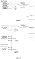
- the power grid When the power supply system of the data center supplies power normally through the power grid, the power grid provides an alternating current to a power supply unit through an automatic transfer switch, and the power supply unit converts the alternating current into a direct current, so as to charge a later level of battery and supply power to a load to be supplied power.
- the automatic transfer switch switches to disconnect an input of the power grid from the power supply unit and connect the oil engine to the power supply unit.
- the oil engine provides an alternating current to the power supply unit through the automatic transfer switch, and the power supply unit converts the alternating current into a direct current to supply power to a load to be supplied power.
- a power supply system and a power supply method are provided, so as to solve a problem in the conventional technology that power supply time is short and power supply reliability is poor in a case of supplying power to a load.
- the high frequency negative pulse discharging is performed on the battery pack, vulcanization of the battery can be weakened, a life of the battery pack can be extended, and therefore power preparation for long time can be achieved using a small delay battery.
- the DC/DC module may be configured to control a switch circuit connected in parallel with the battery pack to perform high frequency negative pulse discharging on the battery pack after the reception of the instruction transmitted by the control unit for performing high frequency negative pulse discharging on the battery pack.
- control unit may be configure to, in a case that the power of the current oil engine is greater than the power of the current loads, prohibit turning off the current loads and instruct the power supply unit to supply power to the battery pack unit and the current loads; in a case that the power of the oil engine is not greater than the power of the current loads, turn off a first number of current loads starting from the load with a low priority according to an ascending order of priorities of the current loads; and in a case that the loads with priority levels less than a preset level each are turned off and the power of the current oil engine is not greater than the power of the current loads, instruct the DC/DC module to control the battery pack to supply power to the current loads.
- the automatic transfer switch unit may be a plurality of single-pole double-throw switches.
- a power supply method which includes:
- the number of the current loads is controlled according to relationship between the power of the current oil engine and the power of the current loads, and priority levels of the loads, such that power supply time can be extended and a case can be avoided that a power supply is powered off due to insufficient power supply time, thereby improving power supply reliability.
- the method may further include:
- control unit can monitor a state of the power grid alternating current output interface and control the automatic transfer switch unit to be connected to the power grid input unit or the oil engine input unit according to whether the power grid alternating current interface outputs the alternating current signal normally.
- the power grid alternating current interface outputs the alternating current signal to supply power to the loads.
- power is supplied to the loads by the oil engine input unit.
- the system further includes a battery pack unit 106, wherein the power supply unit 104 is further configured to provide the direct current signal to the battery pack unit; the control unit 105 is further configured to instruct the power supply unit to control the battery pack to supply power to the current loads; and the battery pack unit 106 is configured to supply power to the current loads under control of the power supply unit.
- the power supply unit 104 includes a rectification module 201 and a DC/DC module 202, wherein the rectification module 201 is configured to convert the received alternating current signal into a direct current signal and output the direct current signal to the DC/DC module; and the DC/DC module 202 is configured to perform high frequency isolation on the direct current signal inputted by the rectification module, and adjust an output voltage value so as to output to the battery pack unit and the current loads.
- the DC/DC module 202 is configured to control a switch circuit connected in series with the battery pack to perform high frequency negative pulse discharging on the battery pack, after the reception of the instruction transmitted by the control unit for performing negative pulse discharging on the battery pack.
- control unit 105 is configured to prohibit turning off the current loads and instruct the power supply unit to supply power to the battery pack unit and the current loads, in a case that a power of the current oil engine is greater than power of the current loads; turn off a first number of current loads starting from the load with a low priority according to an ascending order of priorities of the current loads, in a case that the power of the current oil engine is not greater than the power of the current loads; and instruct the DC/DC module to control the battery pack to supply power to the current loads in a case that all loads with a priority level less than a preset level each are turned off and the power of the current oil engine is not greater than the power of the current loads.
- a power supply system is provided according to a first embodiment of the present disclosure, and a schematic structural diagram of which is shown in Figure 3 .
- the power supply system includes: a power grid input unit 301, an oil engine input unit 302, an automatic transfer switch unit 303, a power supply unit 304, a control unit 305 and a battery pack unit 306.
- the power supply system may supply power in two operation modes: a power grid power supply mode and an oil engine power supply mode. Specific operation principles are as follows.
- the control unit 305 detects that the current of the battery pack is not greater than a preset current value, the control unit 305 transmits an instruction to the DC/DC module 3042 to perform high frequency negative pulse discharging on the battery pack. After the reception of the instruction, the DC/DC module 3042 controls a switch circuit connected in series with the battery pack to perform high frequency negative pulse discharging on the battery pack.
- the alternating current signal provided by the power grid input unit 301 or the oil engine input unit 302 is converted into a direct current signal after passing through the rectification module 3041.
- the rectification module 341 outputs the direct current signal to the DC/DC module 3042, and the DC/DC module 3042 performs high frequency isolation on the direct current signal inputted by the rectification module and adjusts an output voltage value, thereby charging battery packs in the battery pack unit 306 and supplying power to the loads.
- Priorities are set for respective loads in advance according to importance of the respective loads.
- Corresponding switches are provided for each path of loads, and the switches are operated to switch the loads so as to control the loads.
- the power of the current oil engine is greater than the power of the current loads, the power of the current oil engine can meet power supply requirements of respective loads, all load switches are closed and in a normal operation state, and the control unit 305 controls to prohibit turning off the current loads and instruct the power supply unit 304 to supply power to the battery pack unit and all the current loads.
- a first number of current loads are turned off starting from a load to be supplied power with a low priority according to an ascending order of priorities of the current loads.
- the first number may be set flexibly according to actual experiences and need. For example, a load with the lowest priority is closed, and then the magnitude relationship between the power of the current oil engine and the power of the current loads is determined after the load is closed; and if the power of the current oil engine is still not greater than the power of the current loads, a load with the lowest priority in the remaining loads is turned off continuously. In a case that all current loads with a priority level less than a preset level are turned off and the power of the current oil engine is not greater than the power of the current loads, the control unit 304 instructs the DC/DC module to control the battery pack to supply power to the current loads. In this case, both the oil engine and the battery pack supply power to the current loads.
- the batteries discharge continuously until the batteries are in an under voltage protection state.
- priority levels are set for respective loads in advance according to importance of the respective loads, such that the loads are managed intelligently, thereby extending power supply time for the loads with a high priority more efficiently using the power of the oil engine.
- the power supply system includes a power grid input unit 401, an oil engine input unit 402, an automatic transfer switch unit 403, a power supply unit 404, a control unit 405, a battery pack unit 406, a rectification module 4041 and a DC/DC module 4042.
- the power supply system may be implemented by multiple rectification modules connected in parallel with multiple DC/DC modules.
- the power supply system includes a power grid input unit 501, an oil engine input unit 502, an automatic transfer switch unit 503, a power supply unit 504, a control unit 505, a battery pack unit 506, rectification modules 5041 and DC/DC modules 5042.
- the power input unit 301 and the oil engine input unit 302 may provide a single phase alternating current signal.
- the automatic transfer switch unit 303 may be connected to the alternating current signal interface through two single-pole double-throw switches, and the rectification module may be implemented as a rectification circuit in the conventional technology for converting a single phase alternating current signal into a direct current signal, which is not described in detail here.
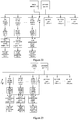
- step 601 a control unit monitors an operation state of a power grid input unit.
- the control unit controls the number of the current loads according to relationship between the power of the oil engine and the power of the current loads and priority levels of the loads, such that the power supply time can be extended and a case that the power supply is powered off due to insufficient power supply time can be avoided, thereby improving power supply reliability.
- negative pulse discharging recovering is performed on the battery pack, such that vulcanization of the batteries can be reduced, thereby extending the life of the batteries.
- the power supply system includes the power grid input unit, the oil engine input unit, the automatic transfer switch unit, the power supply unit, the control unit and the battery pack unit.
- the power grid input unit is configured to provide an alternating current to the power supply unit;
- the oil engine input unit is configured to provide an alternating current to the power supply unit;
- the automatic transfer switch unit is configured to, in response to an instruction of the control unit, connect the power grid input unit to the power supply unit via the switch when the power grid input unit supplies power normally; and connect the oil engine input unit to the power supply unit by switching the switch when the power grid input unit stops supplying power;
- the power supply unit is configured to convert the received alternating current into a direct current to provide to the battery pack unit and supply power to the current loads;
- the control unit is configured to monitor an operation state of the power grid operation unit; control the automatic transfer switch unit to be connected to be power grid input unit when it is monitored that the power grid input unit operates normally; control the automatic transfer switch unit to be connected to the oil engine input unit
- the alternating electric equipment group 30 may include a main input terminal 31, a direct current input terminal 32 and a bypass input terminal 33.
- two input terminals of the ATS switching module 50 are connected to the mains network 11 and the generator 21 respectively, and an output terminal of the ATS switching module 50 is connected to the main input terminal 31 and the bypass input terminal 33 of the alternating current electric equipment group 30, so as to serve as a main power supply and a bypass power supply.
- the direct input terminal 32 of the alternating current electric equipment group 30 is connected to the storage battery 40. When the mains network 11 is normal, power is supplied to the alternating current electric equipment group 30 by the mains network 11 through the main input terminal 31.
- the capacitive load is weak; and in order to improve the reliability of the system, generally it is required to configure the capacity of the diesel generator to be about 2 times of all the alternating current electric equipments.
- the alternating current electric equipment group 30 does not operate at full capacity, it also needs to provide the generator 21 with a great capacity, so as to satisfy the requirement on the suppress of a reactive power and input harmonics of the input capacitor.
- another power supply system including an AC/DC converting module is further provided according to an embodiment of the present disclosure, which can reduce the configuration of the generator effectively.
- a third embodiment of the present disclosure further provides another power supply system, which may particularly function as a power distribution system of a data machine room.
- the power supply system may further include at least an alternating current electric equipment group 30, a storage battery 40 and an AC/DC converting module 60.
- the oil engine input unit 102 outputs an alternating current signal using an oil engine 20.
- the oil engine 20 is also referred to as an oil generator, and the oil engine 20 is a diesel generator or a gasoline generator.
- the alternating current electric equipment group 30 may include various types of alternating current electric equipments, for example an uninterrupted power supply (UPS) system, a high voltage direct current (HVDC) output system or an air conditioner and so on.
- UPS uninterrupted power supply
- HVDC high voltage direct current
- both the AC/DC converting module 60 and the storage battery 40 supply power, such that the oil engine 20 can adapt to a load with a pulsed power requirement, thereby reducing the capacity configuration of the oil engine 20.
- the AC/DC converting module 60 charges the storage battery 40 and supplies power to the loads. With the method, the load with the pulsed power requirement is achieved using a small oil engine 20, thereby saving the investment.
- the bypass input terminal 33 of the alternating current electric equipment group 30 is connected to the oil engine 20, such that the system may switch to the bypass input terminal 33 and the oil engine 20 functions as a bypass power supply to supply power to the alternating current electric equipment group 30, when the inverting module in the alternating current electric equipment group 30 for inverting the direct current input is damaged.
- the oil engine 20 is connected to the bypass input terminal 33, thereby functioning as the last power supply barrier to ensure the normal operation of the system.
- the reactive power compensation module 71 may be added in the conventional power distributing system shown in Figure 7 or Figure 8 and connected to the output terminal of the oil engine 20, so as to improve the performance of the load of the oil engine through reactive power compensation, such that it is beneficial to select the diesel generator 20 with a small capacity.
- the power adaptive ability of the alternating current power supply in the conventional power distributing system is not strong
- another power supply system and power supply method are further provided according to the embodiment of the present disclosure.
- the AC/DC module and its monitoring module are provided without increasing the input power, thereby improving the adaptive ability of the pulsed power and effectively increasing continuity of power supply of the system.
- FIG. 14 Another embodiment of the power supply system is further provided according to a seventh embodiment of the present disclosure, and the embodiment includes an AC/DC device.
- the AC/DC device and a power supply system including the AC/DC device in the embodiment of the present disclosure are described in detail in conjunction with Figure 14 .
- the power supply system further includes: an alternating current power supply 70, multiple loads and at least one storage battery pack, wherein the alternating current power supply 70 is an oil engine, for example a diesel generator set or a gasoline generator set.
- the oil engine input unit 102 outputs an alternating current signal using an oil engine.
- the automatic transfer switch unit 103 connects the oil engine input unit 102 to the power supply unit 104, thereby providing an alternating current signal outputted by the oil engine input unit 102 to the power supply unit 104.
- the power supply unit 104 converts the alternating current signal outputted by the oil engine input unit 102 into a direct current signal, and supplies power to a current load using the direct current signal. Therefore, when an abnormal alternating current is outputted by the power grid alternating current interface, the alternating current power supply 70 supplies power to the multiple loads.
- the multiple loads may be the first load 80-1 to a (m+n)-th load 80-m+n in Figure 14 for example.
- the power supply unit 104 When an abnormal alternating current is outputted by the power grid alternating current interface, the power supply unit 104 includes an AC/DC device.
- the AC/DC device in the present disclosure includes a monitoring module (not shown in Figure 14 ) and at least one AC/DC module.
- the at least one AC/DC module is configured correspondingly to at least one of the multiple loads and at least one storage battery.
- a first AC/DC module 90-1 and a first storage battery pack 100-1 are provided for the first load 80-1
- a second AC/DC module 90-2 and a second storage battery pack 100-2 are provided for the second load 80-2
- an m-th AC/DC module 90-m and an m-th storage battery pack 100-m are provided for the m-th storage battery pack 100-m.
- the AC/DC module is configured to convert an alternating current outputted by the alternating current power supply 70 into a direct current. When the system operates, it may be controlled such that power is supplied to the loads in the second load group by the corresponding AC/DC module, or by the corresponding storage battery pack, or by both the AC/DC module and the storage battery pack.
- the loads in the second load group may include an uninterrupted power supply and an electric equipment.
- the monitoring module is connected to respective AC/DC modules, detects a total output current of the alternating current power supply 70, transmits an instruction to control an input power of the at least one AC/DC module according to the total output current of the alternating current power supply 70, such that the total output power of the alternating current power 70 is not higher than a preset power.
- the preset power is a value slightly lower than a rated power of the alternating current power supply.
- the modules have a function of AC/DC converting, and may control the input power in response to the instruction from the monitoring module, thereby controlling the total output power of the alternating current power supply 70.
- each AC/DC module is connected to an alternating current output terminal of the alternating current power supply 70 such as a diesel generator; the monitoring module determines whether to transmit an instruction to start the AC/DC module in the second load group by detecting the total output current of the alternating current power supply 70, for example a current at the point A in Figure 14 , and detects the total output current of the alternating current power supply in a real-time manner after the AC/DC module is started, thereby controlling the input power of each AC/DC module. For example, a current at the point B in Figure 14 is controlled by adjusting an input current of each AC/DC module; and since a current at the point C does not change, thereby controlling the total output power of the whole alternating current power supply 70.
- the monitoring module determines whether to transmit an instruction to start the AC/DC module in the second load group by detecting the total output current of the alternating current power supply 70, for example a current at the point A in Figure 14 , and detects the total output current of the alternating current power supply in a real
- the monitoring module is connected to an alternating current output terminal of the alternating current power supply 70; and is configured to detect the total output current of the alternating current power supply 70 when the system is started, and transmit an instruction to start each AC/DC module in a case that the total output current is less than a set value.
- respective AC/DC modules may be started simultaneously or started one by one.
- the total output current of the alternating current power supply 70 is great, i.e., not less than the set value, when the system is started, respective AC/DC modules in the second load group are not started, and power is supplied to the loads in the second load group by the connected storage battery pack, thereby controlling the total output current of the alternating current power supply 70 not to exceed a preset power.
- the total output current of the alternating current power supply 70 is small, i.e., greater than the set value, when the system is started, the alternating current power supply 70 can supply power to the loads in the second load group through the respective AC/DC modules, therefore the respective AC/DC modules may be started. In this case, the respective AC/DC modules may supply power to the loads in combination with the storage battery pack.
- the monitoring module may control the respective AC/DC modules to increase an input power thereof, such that the total output current of the alternating current power supply 70 gradually increases, thereby avoiding that the total output power of the alternating current power supply 70 increases suddenly and exceeds the preset power.
- the monitoring module continuously detects whether the total output current of the alternating current power supply 70 is less than the set value; transmits an instruction to respective AC/DC modules to gradually increase the input power thereof in a case that the total output current is less than the set value, such that the total output current of the alternating current power supply 70 increases; and transmits an instruction to the respective AC/DC modules to gradually decrease the input power thereof in a case that the total output current is not less than the set value, such that the total output current of the alternating current power supply 70 decreases. That is, the control process needs to meet a requirement that the total output power of the alternating current power supply 70 is not higher than the set value.
- a preset power of the alternating current power supply 70 can meet the demand of the all loads, the input power of the respective AC/DC modules are balanced and the storage battery is not started as much as possible to supply power. If the preset power of the alternating current power supply 70 can meet the demand of all loads and there is remaining power, the AC/DC modules may charge the storage battery pack connected thereto. If the preset power of the alternating current power supply 70 can not meet the demand of all loads, the monitoring module controls the AC/DC module to start the connected storage battery pack to supply power in a combined manner.
- the monitoring module may determine how to adjust the input power of the AC/DC module connected to each storage battery pack according to the remaining electric quantity of the storage battery pack. After the respective AC/DC modules are started, remaining electric quantities of respective storage battery packs are detected, the storage battery packs are ranked in an ascending order according to the remaining electric quantities, one or more storage battery packs with the lowest remaining electric quantity are selected, and an input power of AC/DC modules connected to the one or more storage battery packs is increased.
- the AC/DC module 90 may further include a charging control unit 93 configured to control charging and discharging of a storage battery pack connected thereto.
- the power supply method according to the present disclosure further includes a control method.
- the control method includes the following steps: detecting a total output current of the alternating current power supply 70, and transmitting an instruction to control an input power of respective AC/DC modules according to the total output current of the alternating current power supply 70, such that the total output power of the alternating current power supply is not higher than a preset power.
- the preset power is a value slightly lower than a rated power of the alternating current power supply.
- step S1602 a total output current of an alternating current power supply 70 is detected.
- step S1606 it is detected whether the total output current of the alternating current power supply is less than a set value; the method proceeds to step S1605, an instruction is transmitted to respective AC/DC modules to gradually increase an input power such that the total output current of the alternating current power supply increases, if the total output current is less than the set value; otherwise, the method proceeds to step S1607.
- the system may randomly reduce an input power of one or more of the respective AC/DC modules, thereby reducing a total output current of the alternating current power supply 70.
- the system may reduce input power of respective AC/DC modules by average, thereby reducing the total output current of the alternating current power supply 70.
- the system may control the AC/DC modules to supply power to the loads in combination with the storage battery pack.
- a charging and discharging state of the storage battery pack may be controlled according to actual cases.
- the input power of the respective AC/DC modules is adjusted using the control method for the power distribution system of the present disclosure according to a principle of balance.
- output current states of respective AC/DC modules and input current states of loads connected to the AC/DC modules may be collected.
- the input power of the respective AC/DC modules are controlled, so as to ensure that the output current of the AC/DC module is greater than or equal to the input current of the load and the battery does not discharge excessively.
- step S1607 an instruction is transmitted to respective AC/DC modules to gradually decrease an input power thereof, such that the total output current of the alternating current power supply decreases, and the method proceeds to step S1606, it is detected again.
- the flow may end when the system stops.
- the flexible power supply system further includes a control module (not shown in Figure 18 ) configured to detect a total output power of the generator set during a time period when the system operates; control the AC/DC module in the second load group to supply power to a corresponding load in combination with the energy storage module when it is determined that the total output power of the generator set 110 reaches a preset power, so as to control the total output power of the generator set not to be higher than a rated power.
- the control module further increases an input power of the second load group when it is determined that the total output power of the generator set 110 is lower than a preset power; and control the AC/DC module to store energy for the energy storage module when supplying power to a corresponding load.
- the control module When increasing the input power of the second load group, the control module should ensure that the total output power of the generator set 110 is not higher than the rated power.
- the preset power described above may be 70% to 100% of the rated power of the generator set 110.
- the load in the first load group is an air conditioner device.
- a rated power configuration of the generator set 110 can be reduced without changing the total output power of the generator set 110. It should be noted that, in configuring the generator set 110, the output power of the generator set 110 needs to be slightly greater than the average power of the system, so as to maintain energy conservation.
- the computer program instructions may also be stored in a computer readable memory which can guide the computer or other programmable data processing device to work in a specific way, such that the instructions stored in the computer readable memory generate a product including an instruction apparatus, and the instruction apparatus implements functions specified in one or more flows of the flowcharts and/or one or more blocks of the block diagrams.
Applications Claiming Priority (6)
| Application Number | Priority Date | Filing Date | Title |
|---|---|---|---|
| CN201410441242.4A CN105406580B (zh) | 2014-09-01 | 2014-09-01 | 一种供电系统和方法 |
| CN201410506106.9A CN105529699B (zh) | 2014-09-28 | 2014-09-28 | 一种ac/dc装置、配电系统及其控制方法 |
| CN201410506085.0A CN105529746B (zh) | 2014-09-28 | 2014-09-28 | 一种柔性配电系统 |
| CN201410506108.8A CN105449720A (zh) | 2014-09-28 | 2014-09-28 | 一种配电系统 |
| PCT/CN2015/088525 WO2016034086A1 (fr) | 2014-09-01 | 2015-08-31 | Système et procédé d'alimentation électrique |
| EP15838675.5A EP3190682B1 (fr) | 2014-09-01 | 2015-08-31 | Système et procédé d'alimentation électrique |
Related Parent Applications (2)
| Application Number | Title | Priority Date | Filing Date |
|---|---|---|---|
| EP15838675.5A Division-Into EP3190682B1 (fr) | 2014-09-01 | 2015-08-31 | Système et procédé d'alimentation électrique |
| EP15838675.5A Division EP3190682B1 (fr) | 2014-09-01 | 2015-08-31 | Système et procédé d'alimentation électrique |
Publications (2)
| Publication Number | Publication Date |
|---|---|
| EP3484015A1 true EP3484015A1 (fr) | 2019-05-15 |
| EP3484015B1 EP3484015B1 (fr) | 2021-06-09 |
Family
ID=55439132
Family Applications (3)
| Application Number | Title | Priority Date | Filing Date |
|---|---|---|---|
| EP15838675.5A Active EP3190682B1 (fr) | 2014-09-01 | 2015-08-31 | Système et procédé d'alimentation électrique |
| EP18208295.8A Active EP3484015B1 (fr) | 2014-09-01 | 2015-08-31 | Système et procédé d'alimentation électrique |
| EP18208993.8A Active EP3487035B1 (fr) | 2014-09-01 | 2015-08-31 | Système et procédé d'alimentation électrique |
Family Applications Before (1)
| Application Number | Title | Priority Date | Filing Date |
|---|---|---|---|
| EP15838675.5A Active EP3190682B1 (fr) | 2014-09-01 | 2015-08-31 | Système et procédé d'alimentation électrique |
Family Applications After (1)
| Application Number | Title | Priority Date | Filing Date |
|---|---|---|---|
| EP18208993.8A Active EP3487035B1 (fr) | 2014-09-01 | 2015-08-31 | Système et procédé d'alimentation électrique |
Country Status (4)
| Country | Link |
|---|---|
| US (4) | US10601246B2 (fr) |
| EP (3) | EP3190682B1 (fr) |
| AU (1) | AU2015311401B2 (fr) |
| WO (1) | WO2016034086A1 (fr) |
Cited By (1)
| Publication number | Priority date | Publication date | Assignee | Title |
|---|---|---|---|---|
| US11444415B2 (en) | 2019-09-30 | 2022-09-13 | Eaton Intelligent Power Limited | Uninterruptible power supplies with replaceable receptacle panels and related methods |
Families Citing this family (43)
| Publication number | Priority date | Publication date | Assignee | Title |
|---|---|---|---|---|
| JP6883396B2 (ja) * | 2016-08-25 | 2021-06-09 | 矢崎総業株式会社 | 急速充電装置 |
| CN106208393B (zh) * | 2016-09-21 | 2019-01-11 | 北京三清互联科技有限公司 | 一种配电网自动化监测方法及系统 |
| CN107869393A (zh) * | 2016-09-23 | 2018-04-03 | 镇江易蝶软件科技有限公司 | 柴油发电机组远程智能控制装置 |
| US20180138741A1 (en) * | 2016-11-16 | 2018-05-17 | Jeffrey Allan Veltri | System and method for local power generation |
| WO2018111977A1 (fr) * | 2016-12-13 | 2018-06-21 | Koolbridge Solar, Inc. | Prises électriques à double alimentation |
| WO2018207515A1 (fr) | 2017-05-11 | 2018-11-15 | 株式会社村田製作所 | Dispositif de commande d'alimentation et procédé de commande d'alimentation |
| US10320220B2 (en) * | 2017-08-23 | 2019-06-11 | Ford Global Technologies, Llc | Configurable hybrid drive systems |
| CN107748516A (zh) * | 2017-10-16 | 2018-03-02 | 安德信微波设备有限公司 | 一种新型通讯控制接口模块 |
| EP3704779A1 (fr) * | 2017-11-03 | 2020-09-09 | Telefonaktiebolaget LM Ericsson (publ) | Station de base et noeud radio utilisables dans un réseau de communication, et leurs procédés d'exploitation |
| US10734821B2 (en) | 2018-03-08 | 2020-08-04 | Saudi Arabian Oil Company | Power control system |
| JP6559388B1 (ja) * | 2018-04-12 | 2019-08-14 | 三菱電機株式会社 | 電力変換システム |
| CN108923526A (zh) * | 2018-09-18 | 2018-11-30 | 国电联合动力技术有限公司 | 一种潮流能发电机组的备用电源装置及其潮流能发电机组 |
| CN110086240A (zh) | 2019-03-28 | 2019-08-02 | 华为技术有限公司 | 一种供电方法、控制方法、供电电源和检测装置 |
| CN109950970A (zh) * | 2019-04-22 | 2019-06-28 | 国家电网有限公司 | 一体化便携式-48v通信应急电源 |
| CN111211615B (zh) * | 2019-10-10 | 2021-07-13 | 杭州电子科技大学 | 一种大型数据中心中压智能负载控制方法及系统 |
| CN110768370B (zh) * | 2019-10-18 | 2021-12-07 | 杭州东氿科技有限公司 | 供配电系统电气设备智能控制系统及方法 |
| CN112051503A (zh) * | 2020-04-14 | 2020-12-08 | 中鹏机电有限公司 | 一种柴油发电机组多路市电监测装置 |
| KR20230011356A (ko) * | 2020-05-18 | 2023-01-20 | 블룸 에너지 코퍼레이션 | 양방향 인버터를 사용한 연료 전지의 작동 방법 |
| US11909007B2 (en) | 2020-07-31 | 2024-02-20 | Volvo Car Corporation | Intelligent battery cell with integrated monitoring and switches |
| US20220037902A1 (en) | 2020-07-31 | 2022-02-03 | Volvo Car Corporation | Configuration of an intelligent battery cell in an operation mode based on parameter data |
| CN112290545B (zh) * | 2020-10-21 | 2022-06-21 | 珠海格力电器股份有限公司 | 一种供电控制装置、方法及多联机空调系统 |
| CN112366786B (zh) * | 2020-11-18 | 2024-05-03 | 南京迅之蜂智能科技有限公司 | 一种智能充电柜及其充电控制方法 |
| CN112713614A (zh) * | 2020-12-22 | 2021-04-27 | 河北电立方新能源科技有限公司 | 一种静态发电机的动态增容控制系统及方法 |
| CN112769220B (zh) * | 2020-12-28 | 2023-03-28 | 广东电网有限责任公司清远供电局 | 电网自动化终端通用备用电源及供电系统 |
| CN112688420A (zh) * | 2021-01-07 | 2021-04-20 | 国网上海市电力公司 | 一种适用多合一站的交直流供电拓扑结构 |
| CN113036893A (zh) * | 2021-03-18 | 2021-06-25 | 山东大学 | 一种带储能电池的大功率充电桩主电路结构 |
| CN112821547A (zh) * | 2021-03-29 | 2021-05-18 | 广东电网有限责任公司电力科学研究院 | 一种应急供电电源及控制方法 |
| CN113078727B (zh) * | 2021-04-02 | 2024-02-23 | 深圳市智莱科技股份有限公司 | 智能换电柜及其供电方法、供电系统和计算机存储介质 |
| CN113078635B (zh) * | 2021-04-07 | 2022-10-28 | 广东电网有限责任公司广州供电局 | 一种多端口背靠背式无缝合环转电装置及方法 |
| CN112953261A (zh) * | 2021-04-21 | 2021-06-11 | 北京百度网讯科技有限公司 | 供电装置和数据处理设备 |
| CN113193646A (zh) * | 2021-04-30 | 2021-07-30 | 北京百度网讯科技有限公司 | 供电装置、方法及系统 |
| CN113329541B (zh) * | 2021-05-18 | 2023-01-20 | 深圳供电局有限公司 | 照明控制系统 |
| CN113595225A (zh) * | 2021-06-23 | 2021-11-02 | 杭州中恒电气股份有限公司 | 一种智能供电系统和方法 |
| CN113595230A (zh) * | 2021-07-29 | 2021-11-02 | 雄安云网科技有限公司 | It设备节能供电系统及方法 |
| CN113839460A (zh) * | 2021-09-02 | 2021-12-24 | 华为数字能源技术有限公司 | 一种供电系统、供电方法和供电装置 |
| CN113852186A (zh) * | 2021-09-29 | 2021-12-28 | 远景能源有限公司 | 一种发电系统的后备电源及其运行方法 |
| CN114336935B (zh) * | 2021-12-27 | 2023-03-28 | 山东高创自动化设备有限公司 | 井下水位监测用能源供给系统 |
| CN114709853B (zh) * | 2022-03-29 | 2024-03-08 | 西北工业大学 | 供电系统和方法 |
| CN114977507A (zh) * | 2022-06-14 | 2022-08-30 | 中国铁塔股份有限公司 | 一种基站配电装置及供电装置 |
| WO2024050656A1 (fr) * | 2022-09-05 | 2024-03-14 | 航霈科技(深圳)有限公司 | Appareil, procédé et système d'alimentation électrique |
| CN115416530B (zh) * | 2022-09-23 | 2024-03-01 | 西安特来电智能充电科技有限公司 | 一种充电方法、设备、存储介质及充电系统 |
| CN115473225B (zh) * | 2022-10-31 | 2023-04-14 | 南京航空航天大学 | 用户隐私主动防御型电能转换系统和方法 |
| CN116454852B (zh) * | 2023-06-14 | 2023-08-15 | 深圳安培时代数字能源科技有限公司 | 供电控制方法及相关装置 |
Citations (6)
| Publication number | Priority date | Publication date | Assignee | Title |
|---|---|---|---|---|
| US5260605A (en) * | 1992-03-05 | 1993-11-09 | Alcatel Network Systems, Inc. | Broadband load disconnect voltage inversion |
| US6134124A (en) * | 1999-05-12 | 2000-10-17 | Abb Power T&D Company Inc. | Universal distributed-resource interface |
| WO2009012451A2 (fr) * | 2007-07-18 | 2009-01-22 | Exaflop Llc | Charge it à couplage direct |
| WO2011039600A1 (fr) * | 2009-10-02 | 2011-04-07 | Panasonic Electric Works Co., Ltd. | Système de commande de charge |
| WO2012162570A1 (fr) * | 2011-05-24 | 2012-11-29 | Cameron D Kevin | Système et procédé pour intégrer et gérer une demande/réponse entre des sources d'énergie alternative, un réseau électrique et des charges |
| US20130187462A1 (en) * | 2010-06-03 | 2013-07-25 | Briggs & Stratton Corporation | Active load management system |
Family Cites Families (17)
| Publication number | Priority date | Publication date | Assignee | Title |
|---|---|---|---|---|
| JP2002014749A (ja) | 2000-06-30 | 2002-01-18 | Mitsubishi Electric Corp | 電源システム |
| US6960838B2 (en) * | 2002-11-15 | 2005-11-01 | Sprint Communications Company L.P. | Power system for a telecommunication facility |
| WO2010111828A1 (fr) | 2009-03-31 | 2010-10-07 | 华为技术有限公司 | Système et procédé d'alimentation électrique |
| CN201616596U (zh) * | 2009-12-14 | 2010-10-27 | 苏州工业园区新宏博通讯科技有限公司 | 单相智能型交流配电箱 |
| TWI425739B (zh) | 2010-11-11 | 2014-02-01 | Dual battery power supply system and control method | |
| CN102480164A (zh) | 2010-11-26 | 2012-05-30 | 中兴通讯股份有限公司 | 混合能源供电系统及方法 |
| JP5311153B2 (ja) | 2011-03-15 | 2013-10-09 | オムロン株式会社 | 電力制御装置および電力制御方法 |
| CN102208830B (zh) * | 2011-03-22 | 2015-02-11 | 艾默生网络能源有限公司 | 一种混合不间断电源系统 |
| CN102377192B (zh) | 2011-10-31 | 2013-11-06 | 清华大学 | 一种直驱型海浪发电储能装置及控制方法 |
| CN102624053B (zh) | 2012-03-22 | 2014-10-29 | 华中科技大学 | 一种可持续供电的不间断电源系统 |
| CN102931687B (zh) | 2012-10-12 | 2014-10-22 | 华北电力大学(保定) | 一种混合储能光伏电站的功率调节方法 |
| CN102931683B (zh) | 2012-11-02 | 2015-04-22 | 浙江工业大学 | 基于变电站典型日负荷曲线的风光直流微电网并网控制方法 |
| CN103855791A (zh) | 2012-11-28 | 2014-06-11 | 中国电信股份有限公司 | 一种发电机智能控制系统 |
| CN103618378A (zh) | 2013-12-10 | 2014-03-05 | 天津市爱和德电源系统有限公司 | 一种油电与光伏供电互补式控制逆变电源 |
| CN103762707B (zh) | 2013-12-31 | 2016-09-14 | 华为技术有限公司 | 太阳能电源、太阳能电源的控制方法及装置 |
| KR20150081731A (ko) * | 2014-01-06 | 2015-07-15 | 삼성에스디아이 주식회사 | 배터리 팩, 배터리 팩을 포함하는 에너지 저장 시스템, 배터리 팩의 작동 방법 |
| US9769948B2 (en) * | 2014-12-10 | 2017-09-19 | Eaton Corporation | Modular uninterruptible power supply apparatus and methods of operating same |
-
2015
- 2015-08-31 WO PCT/CN2015/088525 patent/WO2016034086A1/fr active Application Filing
- 2015-08-31 US US15/507,082 patent/US10601246B2/en active Active
- 2015-08-31 EP EP15838675.5A patent/EP3190682B1/fr active Active
- 2015-08-31 AU AU2015311401A patent/AU2015311401B2/en active Active
- 2015-08-31 EP EP18208295.8A patent/EP3484015B1/fr active Active
- 2015-08-31 EP EP18208993.8A patent/EP3487035B1/fr active Active
-
2019
- 2019-04-23 US US16/391,903 patent/US10637284B2/en active Active
- 2019-04-23 US US16/391,830 patent/US10637283B2/en active Active
- 2019-04-23 US US16/391,853 patent/US10658867B2/en active Active
Patent Citations (6)
| Publication number | Priority date | Publication date | Assignee | Title |
|---|---|---|---|---|
| US5260605A (en) * | 1992-03-05 | 1993-11-09 | Alcatel Network Systems, Inc. | Broadband load disconnect voltage inversion |
| US6134124A (en) * | 1999-05-12 | 2000-10-17 | Abb Power T&D Company Inc. | Universal distributed-resource interface |
| WO2009012451A2 (fr) * | 2007-07-18 | 2009-01-22 | Exaflop Llc | Charge it à couplage direct |
| WO2011039600A1 (fr) * | 2009-10-02 | 2011-04-07 | Panasonic Electric Works Co., Ltd. | Système de commande de charge |
| US20130187462A1 (en) * | 2010-06-03 | 2013-07-25 | Briggs & Stratton Corporation | Active load management system |
| WO2012162570A1 (fr) * | 2011-05-24 | 2012-11-29 | Cameron D Kevin | Système et procédé pour intégrer et gérer une demande/réponse entre des sources d'énergie alternative, un réseau électrique et des charges |
Cited By (1)
| Publication number | Priority date | Publication date | Assignee | Title |
|---|---|---|---|---|
| US11444415B2 (en) | 2019-09-30 | 2022-09-13 | Eaton Intelligent Power Limited | Uninterruptible power supplies with replaceable receptacle panels and related methods |
Also Published As
| Publication number | Publication date |
|---|---|
| EP3487035A1 (fr) | 2019-05-22 |
| EP3190682B1 (fr) | 2021-06-02 |
| US10637284B2 (en) | 2020-04-28 |
| US20190252912A1 (en) | 2019-08-15 |
| EP3484015B1 (fr) | 2021-06-09 |
| EP3190682A1 (fr) | 2017-07-12 |
| WO2016034086A1 (fr) | 2016-03-10 |
| US10637283B2 (en) | 2020-04-28 |
| EP3190682A4 (fr) | 2018-08-29 |
| US20170256984A1 (en) | 2017-09-07 |
| US20190252914A1 (en) | 2019-08-15 |
| US10601246B2 (en) | 2020-03-24 |
| EP3487035B1 (fr) | 2021-02-17 |
| US20190252913A1 (en) | 2019-08-15 |
| US10658867B2 (en) | 2020-05-19 |
| AU2015311401B2 (en) | 2018-08-02 |
| AU2015311401A1 (en) | 2017-04-06 |
Similar Documents
| Publication | Publication Date | Title |
|---|---|---|
| US10658867B2 (en) | Power supply system and method | |
| EP2528181B1 (fr) | SYSTÈME D'ALIMENTATION ÉLECTRIQUE AVEC INTÉGRATION D'ÉNERGIE ÉOLIENNE, D'ÉNERGIE SOLAIRE, d' un générateur DIESEL ET D'ALIMENTATION SECTEUR | |
| US10298006B2 (en) | Energy storage system and method of driving the same | |
| EP3952057B1 (fr) | Alimentation électrique sans interruption modulaire et procédé de fonctionnement d'une alimentation électrique sans interruption modulaire | |
| US20140361624A1 (en) | Apparatus and methods for control of load power quality in uninterruptible power systems | |
| CN105406580B (zh) | 一种供电系统和方法 | |
| US20130002027A1 (en) | Uninterruptible power supply | |
| KR20200048913A (ko) | 폐배터리 기반의 독립형 가정용 에너지 저장 시스템 | |
| JP2015195674A (ja) | 蓄電池集合体制御システム | |
| US9257859B2 (en) | Dynamic battery control based on demand | |
| JP2013070551A (ja) | マルチ出力無停電電源装置 | |
| KR101805273B1 (ko) | 온라인 ups 기능이 내장된 에너지 저장 시스템 및 그 동작 방법 | |
| KR20180136177A (ko) | 에너지 저장 시스템 | |
| CN104578154A (zh) | 一种给煤机低电压穿越的方法 | |
| CN105529699A (zh) | 一种ac/dc装置、配电系统及其控制方法 | |
| CA3019619C (fr) | Dispositif de connexion d'alimentation electrique, et son procede de commande de charge-decharge | |
| JP2012253842A (ja) | 電力供給システム | |
| CN109804520B (zh) | 电力转换系统、电力供给系统及电力转换装置 | |
| KR101215396B1 (ko) | 방전전류제어를 이용한 하이브리드 스마트그리드 무정전전원장치 | |
| CN105529746B (zh) | 一种柔性配电系统 | |
| CN110932333A (zh) | 一种配电系统 | |
| US8760005B2 (en) | Control method of an uninterruptible power supply for extending a discharge time under a no-load condition | |
| CN219576654U (zh) | 共用电池的微电网电路系统及储能设备 | |
| KR20150046540A (ko) | 직류 배전용 백업 배터리를 가지는 led조명 시스템 | |
| CN115483744A (zh) | 一种储能系统的转换电源和自主补电方法 |
Legal Events
| Date | Code | Title | Description |
|---|---|---|---|
| PUAI | Public reference made under article 153(3) epc to a published international application that has entered the european phase |
Free format text: ORIGINAL CODE: 0009012 |
|
| STAA | Information on the status of an ep patent application or granted ep patent |
Free format text: STATUS: THE APPLICATION HAS BEEN PUBLISHED |
|
| AC | Divisional application: reference to earlier application |
Ref document number: 3190682 Country of ref document: EP Kind code of ref document: P |
|
| AK | Designated contracting states |
Kind code of ref document: A1 Designated state(s): AL AT BE BG CH CY CZ DE DK EE ES FI FR GB GR HR HU IE IS IT LI LT LU LV MC MK MT NL NO PL PT RO RS SE SI SK SM TR |
|
| STAA | Information on the status of an ep patent application or granted ep patent |
Free format text: STATUS: REQUEST FOR EXAMINATION WAS MADE |
|
| 17P | Request for examination filed |
Effective date: 20191001 |
|
| RBV | Designated contracting states (corrected) |
Designated state(s): AL AT BE BG CH CY CZ DE DK EE ES FI FR GB GR HR HU IE IS IT LI LT LU LV MC MK MT NL NO PL PT RO RS SE SI SK SM TR |
|
| STAA | Information on the status of an ep patent application or granted ep patent |
Free format text: STATUS: EXAMINATION IS IN PROGRESS |
|
| 17Q | First examination report despatched |
Effective date: 20200429 |
|
| STAA | Information on the status of an ep patent application or granted ep patent |
Free format text: STATUS: EXAMINATION IS IN PROGRESS |
|
| RIC1 | Information provided on ipc code assigned before grant |
Ipc: H02J 9/06 20060101AFI20201119BHEP Ipc: H02J 9/08 20060101ALI20201119BHEP Ipc: H02J 1/14 20060101ALI20201119BHEP Ipc: F02B 3/06 20060101ALN20201119BHEP |
|
| RIC1 | Information provided on ipc code assigned before grant |
Ipc: H02J 9/08 20060101ALI20201120BHEP Ipc: F02B 3/06 20060101ALN20201120BHEP Ipc: H02J 1/14 20060101ALI20201120BHEP Ipc: H02J 9/06 20060101AFI20201120BHEP |
|
| RIC1 | Information provided on ipc code assigned before grant |
Ipc: H02J 9/06 20060101AFI20201208BHEP Ipc: H02J 1/14 20060101ALI20201208BHEP Ipc: F02B 3/06 20060101ALN20201208BHEP Ipc: H02J 9/08 20060101ALI20201208BHEP |
|
| RIC1 | Information provided on ipc code assigned before grant |
Ipc: F02B 3/06 20060101ALN20201223BHEP Ipc: H02J 9/08 20060101ALI20201223BHEP Ipc: H02J 9/06 20060101AFI20201223BHEP Ipc: H02J 1/14 20060101ALI20201223BHEP |
|
| GRAP | Despatch of communication of intention to grant a patent |
Free format text: ORIGINAL CODE: EPIDOSNIGR1 |
|
| STAA | Information on the status of an ep patent application or granted ep patent |
Free format text: STATUS: GRANT OF PATENT IS INTENDED |
|
| INTG | Intention to grant announced |
Effective date: 20210204 |
|
| GRAS | Grant fee paid |
Free format text: ORIGINAL CODE: EPIDOSNIGR3 |
|
| GRAA | (expected) grant |
Free format text: ORIGINAL CODE: 0009210 |
|
| STAA | Information on the status of an ep patent application or granted ep patent |
Free format text: STATUS: THE PATENT HAS BEEN GRANTED |
|
| AC | Divisional application: reference to earlier application |
Ref document number: 3190682 Country of ref document: EP Kind code of ref document: P |
|
| AK | Designated contracting states |
Kind code of ref document: B1 Designated state(s): AL AT BE BG CH CY CZ DE DK EE ES FI FR GB GR HR HU IE IS IT LI LT LU LV MC MK MT NL NO PL PT RO RS SE SI SK SM TR |
|
| REG | Reference to a national code |
Ref country code: GB Ref legal event code: FG4D |
|
| REG | Reference to a national code |
Ref country code: CH Ref legal event code: EP Ref country code: AT Ref legal event code: REF Ref document number: 1401279 Country of ref document: AT Kind code of ref document: T Effective date: 20210615 |
|
| REG | Reference to a national code |
Ref country code: DE Ref legal event code: R096 Ref document number: 602015070363 Country of ref document: DE |
|
| REG | Reference to a national code |
Ref country code: IE Ref legal event code: FG4D |
|
| REG | Reference to a national code |
Ref country code: LT Ref legal event code: MG9D |
|
| PG25 | Lapsed in a contracting state [announced via postgrant information from national office to epo] |
Ref country code: BG Free format text: LAPSE BECAUSE OF FAILURE TO SUBMIT A TRANSLATION OF THE DESCRIPTION OR TO PAY THE FEE WITHIN THE PRESCRIBED TIME-LIMIT Effective date: 20210909 Ref country code: FI Free format text: LAPSE BECAUSE OF FAILURE TO SUBMIT A TRANSLATION OF THE DESCRIPTION OR TO PAY THE FEE WITHIN THE PRESCRIBED TIME-LIMIT Effective date: 20210609 Ref country code: LT Free format text: LAPSE BECAUSE OF FAILURE TO SUBMIT A TRANSLATION OF THE DESCRIPTION OR TO PAY THE FEE WITHIN THE PRESCRIBED TIME-LIMIT Effective date: 20210609 Ref country code: HR Free format text: LAPSE BECAUSE OF FAILURE TO SUBMIT A TRANSLATION OF THE DESCRIPTION OR TO PAY THE FEE WITHIN THE PRESCRIBED TIME-LIMIT Effective date: 20210609 |
|
| REG | Reference to a national code |
Ref country code: AT Ref legal event code: MK05 Ref document number: 1401279 Country of ref document: AT Kind code of ref document: T Effective date: 20210609 |
|
| REG | Reference to a national code |
Ref country code: NL Ref legal event code: MP Effective date: 20210609 |
|
| PG25 | Lapsed in a contracting state [announced via postgrant information from national office to epo] |
Ref country code: GR Free format text: LAPSE BECAUSE OF FAILURE TO SUBMIT A TRANSLATION OF THE DESCRIPTION OR TO PAY THE FEE WITHIN THE PRESCRIBED TIME-LIMIT Effective date: 20210910 Ref country code: NO Free format text: LAPSE BECAUSE OF FAILURE TO SUBMIT A TRANSLATION OF THE DESCRIPTION OR TO PAY THE FEE WITHIN THE PRESCRIBED TIME-LIMIT Effective date: 20210909 Ref country code: LV Free format text: LAPSE BECAUSE OF FAILURE TO SUBMIT A TRANSLATION OF THE DESCRIPTION OR TO PAY THE FEE WITHIN THE PRESCRIBED TIME-LIMIT Effective date: 20210609 Ref country code: RS Free format text: LAPSE BECAUSE OF FAILURE TO SUBMIT A TRANSLATION OF THE DESCRIPTION OR TO PAY THE FEE WITHIN THE PRESCRIBED TIME-LIMIT Effective date: 20210609 Ref country code: SE Free format text: LAPSE BECAUSE OF FAILURE TO SUBMIT A TRANSLATION OF THE DESCRIPTION OR TO PAY THE FEE WITHIN THE PRESCRIBED TIME-LIMIT Effective date: 20210609 |
|
| PG25 | Lapsed in a contracting state [announced via postgrant information from national office to epo] |
Ref country code: ES Free format text: LAPSE BECAUSE OF FAILURE TO SUBMIT A TRANSLATION OF THE DESCRIPTION OR TO PAY THE FEE WITHIN THE PRESCRIBED TIME-LIMIT Effective date: 20210609 Ref country code: EE Free format text: LAPSE BECAUSE OF FAILURE TO SUBMIT A TRANSLATION OF THE DESCRIPTION OR TO PAY THE FEE WITHIN THE PRESCRIBED TIME-LIMIT Effective date: 20210609 Ref country code: SK Free format text: LAPSE BECAUSE OF FAILURE TO SUBMIT A TRANSLATION OF THE DESCRIPTION OR TO PAY THE FEE WITHIN THE PRESCRIBED TIME-LIMIT Effective date: 20210609 Ref country code: SM Free format text: LAPSE BECAUSE OF FAILURE TO SUBMIT A TRANSLATION OF THE DESCRIPTION OR TO PAY THE FEE WITHIN THE PRESCRIBED TIME-LIMIT Effective date: 20210609 Ref country code: PT Free format text: LAPSE BECAUSE OF FAILURE TO SUBMIT A TRANSLATION OF THE DESCRIPTION OR TO PAY THE FEE WITHIN THE PRESCRIBED TIME-LIMIT Effective date: 20211011 Ref country code: NL Free format text: LAPSE BECAUSE OF FAILURE TO SUBMIT A TRANSLATION OF THE DESCRIPTION OR TO PAY THE FEE WITHIN THE PRESCRIBED TIME-LIMIT Effective date: 20210609 Ref country code: RO Free format text: LAPSE BECAUSE OF FAILURE TO SUBMIT A TRANSLATION OF THE DESCRIPTION OR TO PAY THE FEE WITHIN THE PRESCRIBED TIME-LIMIT Effective date: 20210609 Ref country code: AT Free format text: LAPSE BECAUSE OF FAILURE TO SUBMIT A TRANSLATION OF THE DESCRIPTION OR TO PAY THE FEE WITHIN THE PRESCRIBED TIME-LIMIT Effective date: 20210609 Ref country code: CZ Free format text: LAPSE BECAUSE OF FAILURE TO SUBMIT A TRANSLATION OF THE DESCRIPTION OR TO PAY THE FEE WITHIN THE PRESCRIBED TIME-LIMIT Effective date: 20210609 |
|
| PG25 | Lapsed in a contracting state [announced via postgrant information from national office to epo] |
Ref country code: PL Free format text: LAPSE BECAUSE OF FAILURE TO SUBMIT A TRANSLATION OF THE DESCRIPTION OR TO PAY THE FEE WITHIN THE PRESCRIBED TIME-LIMIT Effective date: 20210609 |
|
| REG | Reference to a national code |
Ref country code: DE Ref legal event code: R097 Ref document number: 602015070363 Country of ref document: DE |
|
| REG | Reference to a national code |
Ref country code: CH Ref legal event code: PL |
|
| PG25 | Lapsed in a contracting state [announced via postgrant information from national office to epo] |
Ref country code: MC Free format text: LAPSE BECAUSE OF FAILURE TO SUBMIT A TRANSLATION OF THE DESCRIPTION OR TO PAY THE FEE WITHIN THE PRESCRIBED TIME-LIMIT Effective date: 20210609 |
|
| PLBE | No opposition filed within time limit |
Free format text: ORIGINAL CODE: 0009261 |
|
| STAA | Information on the status of an ep patent application or granted ep patent |
Free format text: STATUS: NO OPPOSITION FILED WITHIN TIME LIMIT |
|
| REG | Reference to a national code |
Ref country code: BE Ref legal event code: MM Effective date: 20210831 |
|
| PG25 | Lapsed in a contracting state [announced via postgrant information from national office to epo] |
Ref country code: LI Free format text: LAPSE BECAUSE OF NON-PAYMENT OF DUE FEES Effective date: 20210831 Ref country code: DK Free format text: LAPSE BECAUSE OF FAILURE TO SUBMIT A TRANSLATION OF THE DESCRIPTION OR TO PAY THE FEE WITHIN THE PRESCRIBED TIME-LIMIT Effective date: 20210609 Ref country code: CH Free format text: LAPSE BECAUSE OF NON-PAYMENT OF DUE FEES Effective date: 20210831 |
|
| 26N | No opposition filed |
Effective date: 20220310 |
|
| PG25 | Lapsed in a contracting state [announced via postgrant information from national office to epo] |
Ref country code: LU Free format text: LAPSE BECAUSE OF NON-PAYMENT OF DUE FEES Effective date: 20210831 Ref country code: AL Free format text: LAPSE BECAUSE OF FAILURE TO SUBMIT A TRANSLATION OF THE DESCRIPTION OR TO PAY THE FEE WITHIN THE PRESCRIBED TIME-LIMIT Effective date: 20210609 |
|
| PG25 | Lapsed in a contracting state [announced via postgrant information from national office to epo] |
Ref country code: IT Free format text: LAPSE BECAUSE OF FAILURE TO SUBMIT A TRANSLATION OF THE DESCRIPTION OR TO PAY THE FEE WITHIN THE PRESCRIBED TIME-LIMIT Effective date: 20210609 Ref country code: IE Free format text: LAPSE BECAUSE OF NON-PAYMENT OF DUE FEES Effective date: 20210831 Ref country code: BE Free format text: LAPSE BECAUSE OF NON-PAYMENT OF DUE FEES Effective date: 20210831 |
|
| PG25 | Lapsed in a contracting state [announced via postgrant information from national office to epo] |
Ref country code: CY Free format text: LAPSE BECAUSE OF FAILURE TO SUBMIT A TRANSLATION OF THE DESCRIPTION OR TO PAY THE FEE WITHIN THE PRESCRIBED TIME-LIMIT Effective date: 20210609 |
|
| P01 | Opt-out of the competence of the unified patent court (upc) registered |
Effective date: 20230621 |
|
| PG25 | Lapsed in a contracting state [announced via postgrant information from national office to epo] |
Ref country code: HU Free format text: LAPSE BECAUSE OF FAILURE TO SUBMIT A TRANSLATION OF THE DESCRIPTION OR TO PAY THE FEE WITHIN THE PRESCRIBED TIME-LIMIT; INVALID AB INITIO Effective date: 20150831 |
|
| PGFP | Annual fee paid to national office [announced via postgrant information from national office to epo] |
Ref country code: GB Payment date: 20230828 Year of fee payment: 9 |
|
| PGFP | Annual fee paid to national office [announced via postgrant information from national office to epo] |
Ref country code: FR Payment date: 20230825 Year of fee payment: 9 Ref country code: DE Payment date: 20230829 Year of fee payment: 9 |
|
| PG25 | Lapsed in a contracting state [announced via postgrant information from national office to epo] |
Ref country code: MK Free format text: LAPSE BECAUSE OF FAILURE TO SUBMIT A TRANSLATION OF THE DESCRIPTION OR TO PAY THE FEE WITHIN THE PRESCRIBED TIME-LIMIT Effective date: 20210609 |