EP3484009A1 - Hydropower generation system - Google Patents
Hydropower generation system Download PDFInfo
- Publication number
- EP3484009A1 EP3484009A1 EP18200098.4A EP18200098A EP3484009A1 EP 3484009 A1 EP3484009 A1 EP 3484009A1 EP 18200098 A EP18200098 A EP 18200098A EP 3484009 A1 EP3484009 A1 EP 3484009A1
- Authority
- EP
- European Patent Office
- Prior art keywords
- power
- bypass breaker
- frequency converter
- gfc
- voltage
- Prior art date
- Legal status (The legal status is an assumption and is not a legal conclusion. Google has not performed a legal analysis and makes no representation as to the accuracy of the status listed.)
- Granted
Links
Images


Classifications
-
- H—ELECTRICITY
- H02—GENERATION; CONVERSION OR DISTRIBUTION OF ELECTRIC POWER
- H02J—ELECTRIC POWER NETWORKS; CIRCUIT ARRANGEMENTS OR SYSTEMS FOR SUPPLYING OR DISTRIBUTING ELECTRIC POWER; SYSTEMS FOR STORING ELECTRIC ENERGY
- H02J3/00—Circuit arrangements for AC mains or AC distribution networks
- H02J3/38—Arrangements for feeding a single network from two or more generators or sources in parallel; Arrangements for feeding already energised networks from additional generators or sources in parallel
- H02J3/40—Synchronisation of generators for connection to a network or to another generator
-
- F—MECHANICAL ENGINEERING; LIGHTING; HEATING; WEAPONS; BLASTING
- F03—MACHINES OR ENGINES FOR LIQUIDS; WIND, SPRING, OR WEIGHT MOTORS; PRODUCING MECHANICAL POWER OR A REACTIVE PROPULSIVE THRUST, NOT OTHERWISE PROVIDED FOR
- F03B—MACHINES OR ENGINES FOR LIQUIDS
- F03B15/00—Controlling
-
- H—ELECTRICITY
- H02—GENERATION; CONVERSION OR DISTRIBUTION OF ELECTRIC POWER
- H02P—CONTROL OR REGULATION OF ELECTRIC MOTORS, ELECTRIC GENERATORS OR DYNAMO-ELECTRIC CONVERTERS; CONTROLLING TRANSFORMERS, REACTORS OR CHOKE COILS
- H02P9/00—Arrangements for controlling electric generators for the purpose of obtaining a desired output
- H02P9/007—Control circuits for doubly fed generators
-
- H—ELECTRICITY
- H02—GENERATION; CONVERSION OR DISTRIBUTION OF ELECTRIC POWER
- H02P—CONTROL OR REGULATION OF ELECTRIC MOTORS, ELECTRIC GENERATORS OR DYNAMO-ELECTRIC CONVERTERS; CONTROLLING TRANSFORMERS, REACTORS OR CHOKE COILS
- H02P9/00—Arrangements for controlling electric generators for the purpose of obtaining a desired output
- H02P9/10—Control effected upon generator excitation circuit to reduce harmful effects of overloads or transients, e.g. sudden application of load, sudden removal of load, sudden change of load
- H02P9/102—Control effected upon generator excitation circuit to reduce harmful effects of overloads or transients, e.g. sudden application of load, sudden removal of load, sudden change of load for limiting effects of transients
-
- F—MECHANICAL ENGINEERING; LIGHTING; HEATING; WEAPONS; BLASTING
- F05—INDEXING SCHEMES RELATING TO ENGINES OR PUMPS IN VARIOUS SUBCLASSES OF CLASSES F01-F04
- F05B—INDEXING SCHEME RELATING TO WIND, SPRING, WEIGHT, INERTIA OR LIKE MOTORS, TO MACHINES OR ENGINES FOR LIQUIDS COVERED BY SUBCLASSES F03B, F03D AND F03G
- F05B2270/00—Control
- F05B2270/10—Purpose of the control system
- F05B2270/104—Purpose of the control system to match engine to driven device
-
- Y—GENERAL TAGGING OF NEW TECHNOLOGICAL DEVELOPMENTS; GENERAL TAGGING OF CROSS-SECTIONAL TECHNOLOGIES SPANNING OVER SEVERAL SECTIONS OF THE IPC; TECHNICAL SUBJECTS COVERED BY FORMER USPC CROSS-REFERENCE ART COLLECTIONS [XRACs] AND DIGESTS
- Y02—TECHNOLOGIES OR APPLICATIONS FOR MITIGATION OR ADAPTATION AGAINST CLIMATE CHANGE
- Y02E—REDUCTION OF GREENHOUSE GAS [GHG] EMISSIONS, RELATED TO ENERGY GENERATION, TRANSMISSION OR DISTRIBUTION
- Y02E10/00—Energy generation through renewable energy sources
- Y02E10/20—Hydro energy
Definitions
- the present invention relates to a hydropower generation system and is particularly suitable for application to a primary-excitation-type hydropower generation system in which a generator and an electric power system coupled with a water turbine are interconnected via a frequency converter (hereinafter, also referred to as a "FC").
- a frequency converter hereinafter, also referred to as a "FC"
- a hydropower generation system is a power generation system which converts rotation energy into electric energy by rotating a water turbine using a difference in elevation of water and a flow rate of water.
- the hydropower generation system has the form of connecting a FC between primary winding or secondary winding of a generator and a power system, for the high efficiency of a water turbine by the variable rotation speed.
- a self-excited or separately excited AC/DC converter using a semiconductor switching element such as an IGBT and a thyristor is used.
- a primary excitation type of the generator where the FC is connected to the primary winding has been drawing attention in recent years because it has features such as a wider variable speed drive range and contribution to the system stabilization function.
- the effect of the high efficiency of a water turbine by the variable speed is small.
- the power generation efficiency of the system decreases due to power conversion loss of the FC.
- a hydropower generation system of the related art has a main circuit (hereinafter, referred to as a "bypass breaker") for short-circuiting two AC output terminals of a FC.
- a main circuit hereinafter, referred to as a "bypass breaker"
- the generated electric power is transmitted to a power system via the FC by closing an AC breaker of the FC and opening the bypass breaker.
- the flow rate or the generated electric power is larger than the threshold value, the generated electric power is directly supplied to the power system by opening the AC breaker of the FC and closing the bypass breaker.
- An example for solving the problem is to use a speed regulator (a governor) of a water turbine.
- the governor adjusts a flow rate of water flowing into a water turbine and a rotation speed of a generator is changed, in such a manner that a phase difference between the system voltage and the generator voltage is adjusted and a bypass breaker is closed when voltage synchronization is secured.
- a speed regulator a governor
- the governor adjusts a flow rate of water flowing into a water turbine and a rotation speed of a generator is changed, in such a manner that a phase difference between the system voltage and the generator voltage is adjusted and a bypass breaker is closed when voltage synchronization is secured.
- it is necessary to mechanically operate a needle valve or a guide vane, and thus, generally, control response is slow and there is a problem that it takes time to secure voltage synchronization and close the bypass breaker.
- the invention is made in view of the above points and is intended to propose a hydropower generation system capable of achieving both prevention of power fluctuation when a bypass breaker is closed and high-speed voltage synchronization.
- the invention is characterized in that a frequency converter which is provided with two AC output terminals, and/or a water turbine generator which is interconnected to a power system via the frequency converter, and/or a bypass breaker which has both ends for short-circuiting the two AC output terminals in the frequency converter, and/or a control device which controls the frequency converter and the bypass breaker, and and/or a voltage detector which detects two AC voltages at both ends of the bypass breaker are provided, and/or the control device adjusts an output voltage of the frequency converter to a direction in which two AC voltage amplitudes at both ends of the bypass breaker coincide with each other and two voltage phases at both ends of the bypass breaker coincide with each other when the bypass breaker is switched from opening to closing and outputs a closing command for closing the bypass breaker when an amplitude difference and a phase difference of the two AC voltages at both ends of the bypass breaker are within respective certain values.
- both prevention of power fluctuation when a bypass breaker is closed and high-speed voltage synchronization can be achieved.
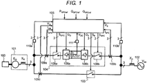
- FIG. 1 is a block diagram illustrating an example of an overall configuration of a hydropower generation system according to a first embodiment.
- a generator 101 is connected to a water turbine 100 and is interconnected to a power system 102 via a bypass breaker 103 and a frequency converter (hereinafter abbreviated as "FC") 104. Generated electric power of the generator 101 is transmitted to the power system 102 via the bypass breaker 103 or the FC 104.
- FC frequency converter
- bypass breaker 103 closing/opening is determined according to a bypass breaker operation signal S B from a control device 105. Details of the bypass breaker 103 will be described hereinafter.
- the FC 104 includes two AC/DC converters 106a and 106b, a DC capacitor 107, and two AC breakers 108a and 108b.
- the AC/DC converter 106a operates with a gate signal G G from the control device 105 and is driven to transmit the generated electric power of the generator 101 to the power system 102.
- the AC/DC converter 106b is operated by a gate signal G S from the control device 105 and is driven in tandem with the power system 102 while a DC voltage V DC of the DC capacitor 107 is controlled to be constant.
- closing/opening is determined based on FC AC breaker operation signals S GFC and S SFC from the control device 105.
- the control device 105 receives detection values obtained from AC current detectors 109a, 109b, and 109c and AC voltage detectors 110a and 110b, an active power command P GFCref of the FC 104, a reactive power command Q SFCref exchanged with the power system 102, and a reactive power command Q GFCref exchanged with the generator 101, and calculates the gate signals G G and G S to be given to the two AC/DC converters 106a and 106b of the FC 104. Further, the control device 105 determines the bypass breaker operation signal S B of the bypass breaker 103 and the FC AC breaker operation signal S GFC , S SFC of the FC AC breakers 108a and 108b.
- the AC current detectors 109a, 109c, and 109b detect a current I GFC flowing from the generator 101 to the FC 104, a current I GB flowing from the generator 101 to the bypass breaker 103, and a current I SFC flowing from the FC 104 to the power system 102, respectively, and input the detected current values to the control device 105.
- the AC voltage detectors 110a and 110b respectively detect a generator voltage V G and a system voltage V S which are voltages at both ends of the bypass breaker 103 and input the detected values to the control device 105.
- a DC voltage detector 111 detects the DC voltage V DC of the DC capacitor 107 existing in the DC circuit of the two AC/DC converters 106a and 106b and inputs it to the control device 105.
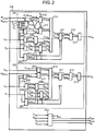
- FIG. 2 illustrates an overall control block diagram illustrating a configuration example of the control device 105 illustrated in FIG. 1 .
- the control device 105 includes a generator terminal control circuit 201 for controlling the AC/DC converter 106a on the generator side, a system terminal control circuit 202 for controlling the AC/DC converter 106b on the system side, and an AC breaker control circuit 203 for controlling closing/opening of the three AC breakers.
- the generator terminal control circuit 201 controls an active power P GFC of the generator 101 which is transmitted to the power system 102 and a reactive power Q GFC exchanged with the generator 101, so as to follow the active power command P GFCref and the reactive power command Q GFCref of the FC 104.
- the system terminal control circuit 202 controls the DC voltage V DC of the DC capacitor 107 so as to follow a DC voltage command value V DCref . Further, the reactive power Q SFC exchanged with the power system 102 is controlled to follow the reactive power command Q SFCref .
- the AC breaker control circuit 203 controls closing/opening of the three AC breakers, that is, the bypass breaker 103 and the FC AC breakers 108a and 108b.
- the AC breaker control circuit 203 has a function of determining the voltage synchronization of the system voltage V S and the generator voltage V G .
- the generator terminal control circuit 201 includes ⁇ - ⁇ coordinate transformations 205 and 206, a system voltage phase detection unit 207, d-q coordinate transformations 208 and 209, an AC current control unit 210, an inverse d-q coordinate transformation 211, an inverse ⁇ - ⁇ coordinate transformation 212, a gate pulse generating unit 213, adders 214a and 214b, a power calculation unit 215, an active power control unit 216, a reactive power control unit 217, and a power command value adjustment unit 218.
- the power command value adjustment unit 218 receives a circuit switching signal S FLG from the AC breaker control circuit 203, the generator voltage V G , the system voltage V S and outputs corrected power commands ⁇ P and ⁇ Q.
- the circuit switching signal S FLG is a signal for controlling circuit switching of the FC 104 and the bypass breaker 103.
- the corrected power commands ⁇ P and ⁇ Q 0 is set.
- the circuit switching signal S FLG is 1, the corrected effective power and the corrected reactive power capable of ensuring voltage synchronization are outputted as the corrected power commands ⁇ P and ⁇ Q.
- Equation (1) a value obtained by dividing the active power P GFC , exchanged by the generator 101 and the FC 104, by the angular frequency ⁇ G corresponds to the electric output torque of the generator 101.
- the generator keeps the machine input torque T M and the electric output torque to zero, in such a manner that the rate of change of ⁇ G of the generator 101 can be controlled to zero, that is, to a constant speed.
- the rotational speed of the generator voltage V G is changed by intentionally setting a change rate d ⁇ G /dt of the rotational speed (rotational frequency) of the generator 101 to a value other than zero. Therefore, the corrected power command ⁇ P is added to the active power P GFC exchanged by the generator 101 and the FC 104 and the corrected power command ⁇ P is obtained from Equation (2).
- ⁇ P ⁇ ⁇ G J d ⁇ G dt ⁇ T M ⁇ P GFC
- the corrected power command ⁇ Q can be calculated by Equation (3) and is obtained from the difference between the reactive power for matching the generator voltage V G with the system voltage V S and the reactive power Q GFC exchanged by the generator 101 and the FC 104.
- ⁇ Q E G V S X G cos ⁇ G ⁇ E G 2 X G ⁇ Q GFC
- E G is the induced voltage of the generator 101
- X G is the leakage reactance of the generator 101
- cos ⁇ G is the power factor angle of the AC/DC converter 106a. Resistance of generator 101 is ignored as being sufficiently smaller than reactance.
- the system terminal control circuit 202 includes a DC voltage control unit 204, ⁇ - ⁇ coordinate transformations 205 and 206, a system voltage phase detection unit 207, d-q coordinate transformations 208 and 209, an AC current control unit 210, an inverse d-q coordinate transformation 211, an inverse ⁇ - ⁇ coordinate transformation 212, a gate pulse generating unit 213, a power calculation unit 215, and a reactive power control unit 217.
- the AC breaker control circuit 203 receives the active power P GFC , the reactive power Q GFC of the FC 104, the generator voltage V G , and the system voltage V S , outputs the circuit switching signal S FLG , and further outputs the bypass breaker operation signal S B and the FC AC breaker operation signals S GFC and S SFC which are closing/opening signals of the bypass breaker 103 and the FC AC breakers 108a and 108b, respectively.
- FIG. 3 is an internal control block diagram illustrating a configuration example of the AC breaker control circuit 203 illustrated in FIG. 2 .
- the AC breaker control circuit 203 includes a circuit switching determination unit 301, amplitude/phase calculation units 302 and 303 of the generator voltage V G and the system voltage V S , a circuit breaker closing/opening signal generation unit 304, and subtractors 305a and 305b.
- the circuit switching determining unit 301 receives the active power P GFC and the reactive power Q GFC of the FC 104, compares the active power P GFC and the reactive power Q GFC of the FC 104 with a circuit switching active power Pth and a circuit switching reactive power Qth which are circuit switching threshold values, respectively, and outputs the circuit switching signal S FLG .
- the circuit switching signal S FLG changes from 0 to 1.
- a value of the circuit switching signal S FLG is held until a switching reset signal S Reset is entered.
- a combination of two values of the active power P GFC and the reactive power Q GFC is used as the circuit switching threshold values.
- the active power P GFC , the reactive power Q GFC , apparent electric power, and the like may be used as the circuit switching threshold values.
- the amplitude/phase calculation units 302 and 303 calculate an amplitude V Gamp and a phase V Gphase of the generator voltage V G and an amplitude V Samp and a phase V Sphase of the system voltage V S .
- the calculated amplitude V Samp and phase V Sphase are subtracted at the subtractors 305a and 305b at the subsequent stage and an amplitude difference V ampDiff and a phase difference V phaseDiff of the two voltages are calculated.
- the amplitude difference V ampDiff and the phase difference V phaseDiff are used to determine voltage synchronization.
- the circuit breaker closing/opening signal generation unit 304 receives the active power P GFC , the reactive power Q GFC of the FC 104, the circuit switching signal S FLG , the amplitude difference V ampDiff , and the phase difference V phaseDiff , and outputs the bypass breaker operation signal S B and the FC AC breaker operation signals S GFC and S SFC which are the closing/opening signals of the bypass breaker 103 and the FC AC breakers 108a and 108b, respectively.
- the amplitude difference V ampDiff and the phase difference V phaseDiff are respectively compared with an amplitude threshold value V amPth and a phase threshold value V phaseth which are corresponding synchronization determination threshold values.
- V amPth and V phaseth are respectively within the synchronization determination threshold values V amPth and V phaseth .
- FIGS. 4A to 4J respectively illustrate examples of waveforms of parts of a hydropower generation system to which the embodiment is applied.
- the circuit switching is performed from an operating state of a FC interconnection operation (the bypass breaker 103 is open and the FC AC breakers 108a and 108b are closed) to a FC bypass operation (the bypass breaker 103 is closed and the FC AC breakers 108a and 108b are open).
- a vertical axis of FIG. 4A indicates the system voltage V S
- a vertical axis of FIG. 4B indicates the generator voltage V G
- a vertical axis of FIG. 4C indicates the active power P GFC of the FC 104
- a vertical axis of FIG. 4D indicates the reactive power Q GFC
- a vertical axis of FIG. 4E indicates the phase difference V phaseDiff between the system voltage Vs and the generator voltage V G
- a vertical axis of FIG. 4F indicates the amplitude difference V ampDiff
- 4G indicates an electric power P GB which is transmitted from the generator 101 to the power system 102 via the bypass breaker 103
- a vertical axis of FIG. 4H indicates the circuit switching signal S FLG of the circuit switching determination unit 301
- a vertical axis of FIG. 4I indicates the FC AC breaker operation signals S GFC and S SFC
- a vertical axis of FIG. 4J indicates the bypass breaker operation signal S B .
- a horizontal axis indicates a time t.
- the breaker operation signals S GFC , S SFC , and S B illustrated in FIG. 4I and 4J open the corresponding breakers when the value is 0, and close them when the value is 1.
- the hydropower generation system of the embodiment performs the FC interconnection operation with an electric power generated at a low level.
- the bypass breaker 103 is open and no current flows, and thus the power P GB to be transmitted to the power system 102 is zero.
- the active power P GFC and the reactive power Q GFC of the FC 104 increase in order to transmit the generated electric power to the power system 102. Then, at the time t2, the active power P GFC and the reactive power Q GFC reach the rated values (P GFCref_ratred , Q GFCref_rated ). At this time, the circuit switching threshold values Pth and Qth are exceeded, and thus the circuit switching signal S FLG of the circuit switching determination unit 301 changes from 0 to 1 and the circuit switching from the FC interconnection operation to the FC bypass operation is executed.
- the circuit switching signal S FLG becomes 1, as the corrected power commands ⁇ P and ⁇ Q of the power command value adjustment unit 218 illustrated in FIG. 2 , values capable of ensuring voltage synchronization are outputted.
- the corrected power commands ⁇ P and ⁇ Q are added to the P GFCref and the Q GFCref of the FC 104 by the adder 214a and 214b, respectively, and an active power command value P GFCref' and a reactive power command value Q GFCref' which are corrected are generated.
- the active power control unit 216 and the reactive power control unit 217 control the active power P GFC and the reactive power Q GFC to follow the corrected active power command value P GFCref' and the corrected reactive power command value Q GFCref' , respectively.
- the instant at which the phase difference V phaseDiff of the generator voltage V G and the system voltage V S crosses the phase threshold value V phaseth always occurs within a certain period. Furthermore, the amplitude V Gamp of the generator voltage V G can be adjusted by adding the corrected power command ⁇ Q, and thus the amplitude difference V ampDiff with the amplitude V Samp of the system voltage can be controlled within the amplitude threshold value V amPth .
- the power command value adjustment unit 218 may be provided with a change rate limiter for increasing or decreasing the corrected power commands ⁇ P and ⁇ Q on respective ramps as illustrated in FIG. 4 , and may be configured to moderate mechanical stress due to rapid acceleration or sudden deceleration of the generator 101 and electrical stress due to voltage sudden change thereof.
- the bypass breaker operation signal S B is set to 1 and the bypass breaker 103 is closed.
- the circuit switching decision unit 301 After it is confirmed that the bypass breaker 103 is closed, the circuit switching decision unit 301 outputs the switching reset signal S Reset and resets a corrected power command output signal S FLG from 1 to 0. As a result, the corrected power commands ⁇ P and ⁇ Q become zero.
- V amPth and V phaseth at which the power fluctuation during the closing of the circuit breaker does not affect the stable operation of the equipment are chosen as described above, and thus the inrush current caused by the closing of the bypass breaker 103 can be suppressed. That is, excessive power fluctuation can be prevented.
- the power command value adjustment unit 218 detects closing (the corrected power command output signal S FLG changes from 1 to 0) of the bypass breaker 103 and outputs the corrected power commands ⁇ P and ⁇ Q which respectively make the active power P GFC and the reactive power Q GFC of the FC 104 zero. That is, the active power P GFC and the reactive power Q GFC of the FC 104 are controlled so that the generated electric power of the generator 101 is transmitted to the power system 102 via the bypass breaker 103, not via the FC 104.
- FC AC breaker operation signals S GFC and S SFC 0
- FC AC breaker operation signals S GFC and S SFC 0
- bypass breaker 103 since the bypass breaker 103 is closed after the voltage synchronization between the system voltage V S and the generator voltage V G is secured in the hydropower generation system, it is possible to prevent excessive power fluctuation. Further, it is not necessary to ensure voltage synchronization by operation of a mechanical part such as a needle valve or a guide vane, so that the circuit switching described above can be performed at high speed.
- FIG. 5 is an overall control block diagram of a hydropower generation system according to a second embodiment. Since the hydropower generation system according to the second embodiment has almost the same configuration and operation as the hydropower generation system according to the first embodiment, the description of the same configuration and operation will not be repeated and the differences will be mainly described hereinafter.
- the voltage synchronization is secured by adding the corrected power commands ⁇ P and ⁇ Q to the generator terminal control circuit 201.
- the system terminal control circuit 202 is provided with a power command value adjustment unit 218 and the corrected power command ⁇ Q is added to the system terminal control circuit 202.
- the generator voltage V G is controlled by a corrective reactive power command ⁇ Q.
- the system voltage V S is controlled by a corrective reactive power command ⁇ Q.
- the corrected power command ⁇ Q in the embodiment can be calculated using Equation (4) and, for example, it is obtained from a difference between the reactive power for matching the system voltage V S and the generator voltage V G and the reactive power Q SFC exchanged between the power system 102 and the FC 104.
- ⁇ Q V S 0 V G X S cos ⁇ S ⁇ V S 0 2 X S ⁇ Q SFC
- V S0 is the voltage of the power system 102
- X S is the interactive reactance with the power system 102
- cos ⁇ S is the power factor angle of the AC/DC converter 106b. The resistance is ignored as being sufficiently smaller than the interactive reactance.
- the invention can be broadly applied for a primary-excitation-type hydropower generation system in which a power generator and a power system coupled with a water turbine are interconnected via a frequency converter.
Landscapes
- Engineering & Computer Science (AREA)
- Power Engineering (AREA)
- Chemical & Material Sciences (AREA)
- Combustion & Propulsion (AREA)
- Mechanical Engineering (AREA)
- General Engineering & Computer Science (AREA)
- Control Of Eletrric Generators (AREA)
Abstract
Description
- The present invention relates to a hydropower generation system and is particularly suitable for application to a primary-excitation-type hydropower generation system in which a generator and an electric power system coupled with a water turbine are interconnected via a frequency converter (hereinafter, also referred to as a "FC").
- A hydropower generation system is a power generation system which converts rotation energy into electric energy by rotating a water turbine using a difference in elevation of water and a flow rate of water. The hydropower generation system has the form of connecting a FC between primary winding or secondary winding of a generator and a power system, for the high efficiency of a water turbine by the variable rotation speed. For the FC, a self-excited or separately excited AC/DC converter using a semiconductor switching element such as an IGBT and a thyristor is used.
- Compared with a secondary excitation type where the FC is connected to the secondary winding, a primary excitation type of the generator where the FC is connected to the primary winding has been drawing attention in recent years because it has features such as a wider variable speed drive range and contribution to the system stabilization function. However, in an operating range close to the generator rating, the effect of the high efficiency of a water turbine by the variable speed is small. In addition, there is a problem that the power generation efficiency of the system decreases due to power conversion loss of the FC.
- In order to solve the problem, a hydropower generation system of the related art has a main circuit (hereinafter, referred to as a "bypass breaker") for short-circuiting two AC output terminals of a FC. When a flow rate or generated electric power is less than a threshold value, the generated electric power is transmitted to a power system via the FC by closing an AC breaker of the FC and opening the bypass breaker. On the other hand, when the flow rate or the generated electric power is larger than the threshold value, the generated electric power is directly supplied to the power system by opening the AC breaker of the FC and closing the bypass breaker. By performing circuit-switching of the FC and the bypass breaker according to the generated electric power and the flow rate of a generator, both avoidance of a decrease in power generation efficiency in an operation region close to a generator rated range and high efficiency of a water turbine in a low power generation region are achieved (see
JP-A-2016-158335 - When circuit-switching is performed from the FC to the bypass breaker, if voltage synchronization of two AC voltages (hereinafter, referred to as a system voltage and a generator voltage) at both ends of the bypass breaker is not maintained, at the moment when the bypass breaker is closed, excessive inrush current caused by a voltage amplitude/phase difference, circuit impedance, etc., flows, and thus there is a problem that electric power fluctuation of the generator and the power system is caused. Therefore, it is desirable to perform circuit switching for a system stable operation while the power fluctuation of the generator and the power system is prevented.
- An example for solving the problem is to use a speed regulator (a governor) of a water turbine. Specifically, the governor adjusts a flow rate of water flowing into a water turbine and a rotation speed of a generator is changed, in such a manner that a phase difference between the system voltage and the generator voltage is adjusted and a bypass breaker is closed when voltage synchronization is secured. However, in the method using the governor, it is necessary to mechanically operate a needle valve or a guide vane, and thus, generally, control response is slow and there is a problem that it takes time to secure voltage synchronization and close the bypass breaker.
- The invention is made in view of the above points and is intended to propose a hydropower generation system capable of achieving both prevention of power fluctuation when a bypass breaker is closed and high-speed voltage synchronization.
- In order to solve the problem, the invention is characterized in that a frequency converter which is provided with two AC output terminals, and/or a water turbine generator which is interconnected to a power system via the frequency converter, and/or a bypass breaker which has both ends for short-circuiting the two AC output terminals in the frequency converter, and/or a control device which controls the frequency converter and the bypass breaker, and and/or a voltage detector which detects two AC voltages at both ends of the bypass breaker are provided, and/or the control device adjusts an output voltage of the frequency converter to a direction in which two AC voltage amplitudes at both ends of the bypass breaker coincide with each other and two voltage phases at both ends of the bypass breaker coincide with each other when the bypass breaker is switched from opening to closing and outputs a closing command for closing the bypass breaker when an amplitude difference and a phase difference of the two AC voltages at both ends of the bypass breaker are within respective certain values.
- According to the invention, both prevention of power fluctuation when a bypass breaker is closed and high-speed voltage synchronization can be achieved.
-
-
FIG. 1 is a block diagram illustrating an example of an overall configuration of a hydropower generation system according to a first embodiment; -
FIG. 2 illustrates an overall control block diagram illustrating a configuration example of a control device illustrated inFIG. 1 ; -
FIG. 3 is an internal control block diagram illustrating a configuration example of a circuit breaker control circuit illustrated inFIG. 2 ; -
FIGS. 4A to 4J respectively illustrate examples of waveforms of parts of a hydropower generation system to which the first embodiment is applied; and -
FIG. 5 is an overall control block diagram of a hydropower generation system according to a second embodiment. - Hereinafter, an embodiment of the invention will be described in detail with reference to the drawings.
-
FIG. 1 is a block diagram illustrating an example of an overall configuration of a hydropower generation system according to a first embodiment. - A
generator 101 is connected to awater turbine 100 and is interconnected to apower system 102 via abypass breaker 103 and a frequency converter (hereinafter abbreviated as "FC") 104. Generated electric power of thegenerator 101 is transmitted to thepower system 102 via thebypass breaker 103 or the FC 104. - In the
bypass breaker 103, closing/opening is determined according to a bypass breaker operation signal SB from acontrol device 105. Details of thebypass breaker 103 will be described hereinafter. - The FC 104 includes two AC/
DC converters AC breakers DC converter 106a operates with a gate signal GG from thecontrol device 105 and is driven to transmit the generated electric power of thegenerator 101 to thepower system 102. On the other hand, the AC/DC converter 106b is operated by a gate signal GS from thecontrol device 105 and is driven in tandem with thepower system 102 while a DC voltage VDC of the DC capacitor 107 is controlled to be constant. - In the two FC AC
breakers control device 105. - The
control device 105 receives detection values obtained fromAC current detectors AC voltage detectors FC 104, a reactive power command QSFCref exchanged with thepower system 102, and a reactive power command QGFCref exchanged with thegenerator 101, and calculates the gate signals GG and GS to be given to the two AC/DC converters control device 105 determines the bypass breaker operation signal SB of thebypass breaker 103 and the FC AC breaker operation signal SGFC, SSFC of the FC ACbreakers - The AC
current detectors generator 101 to theFC 104, a current IGB flowing from thegenerator 101 to thebypass breaker 103, and a current ISFC flowing from theFC 104 to thepower system 102, respectively, and input the detected current values to thecontrol device 105. - The
AC voltage detectors bypass breaker 103 and input the detected values to thecontrol device 105. - A
DC voltage detector 111 detects the DC voltage VDC of the DC capacitor 107 existing in the DC circuit of the two AC/DC converters control device 105. -
FIG. 2 illustrates an overall control block diagram illustrating a configuration example of thecontrol device 105 illustrated inFIG. 1 . Thecontrol device 105 includes a generatorterminal control circuit 201 for controlling the AC/DC converter 106a on the generator side, a systemterminal control circuit 202 for controlling the AC/DC converter 106b on the system side, and an ACbreaker control circuit 203 for controlling closing/opening of the three AC breakers. - The generator
terminal control circuit 201 controls an active power PGFC of thegenerator 101 which is transmitted to thepower system 102 and a reactive power QGFC exchanged with thegenerator 101, so as to follow the active power command PGFCref and the reactive power command QGFCref of the FC 104. - The system
terminal control circuit 202 controls the DC voltage VDC of the DC capacitor 107 so as to follow a DC voltage command value VDCref. Further, the reactive power QSFC exchanged with thepower system 102 is controlled to follow the reactive power command QSFCref. - The AC
breaker control circuit 203 controls closing/opening of the three AC breakers, that is, thebypass breaker 103 and the FC ACbreakers breaker control circuit 203 has a function of determining the voltage synchronization of the system voltage VS and the generator voltage VG. - Next, constituent elements of each circuit will be described with reference to
FIG. 2 and the like. The generatorterminal control circuit 201 includes α-β coordinate transformations phase detection unit 207,d-q coordinate transformations current control unit 210, an inversed-q coordinate transformation 211, an inverse α-β coordinate transformation 212, a gate pulse generating unit 213,adders power calculation unit 215, an activepower control unit 216, a reactivepower control unit 217, and a power commandvalue adjustment unit 218. - Here, the power command
value adjustment unit 218 receives a circuit switching signal SFLG from the ACbreaker control circuit 203, the generator voltage VG, the system voltage VS and outputs corrected power commands ΔP and ΔQ. The circuit switching signal SFLG is a signal for controlling circuit switching of the FC 104 and thebypass breaker 103. In the embodiment, when the circuit switching signal SFLG is 0, the corrected power commands ΔP and ΔQ = 0 is set. On the other hand, when the circuit switching signal SFLG is 1, the corrected effective power and the corrected reactive power capable of ensuring voltage synchronization are outputted as the corrected power commands ΔP and ΔQ. - A specific calculation example of the corrected power commands ΔP and ΔQ is described hereinafter. First, in order to obtain the corrected power command ΔP, an equation of motion of the
generator 101 is obtained by Equation (1).
- Here, J is the moment of inertia of the
generator 101, ωG is the angular frequency of thegenerator 101, and TM is the machine input torque of thegenerator 101. In Equation (1), a value obtained by dividing the active power PGFC, exchanged by thegenerator 101 and theFC 104, by the angular frequency ωG corresponds to the electric output torque of thegenerator 101. - From Equation (1), the generator keeps the machine input torque TM and the electric output torque to zero, in such a manner that the rate of change of ωG of the
generator 101 can be controlled to zero, that is, to a constant speed. In the embodiment, the rotational speed of the generator voltage VG is changed by intentionally setting a change rate dωG/dt of the rotational speed (rotational frequency) of thegenerator 101 to a value other than zero. Therefore, the corrected power command ΔP is added to the active power PGFC exchanged by thegenerator 101 and theFC 104 and the corrected power command ΔP is obtained from Equation (2).
- The corrected power command ΔQ can be calculated by Equation (3) and is obtained from the difference between the reactive power for matching the generator voltage VG with the system voltage VS and the reactive power QGFC exchanged by the
generator 101 and theFC 104.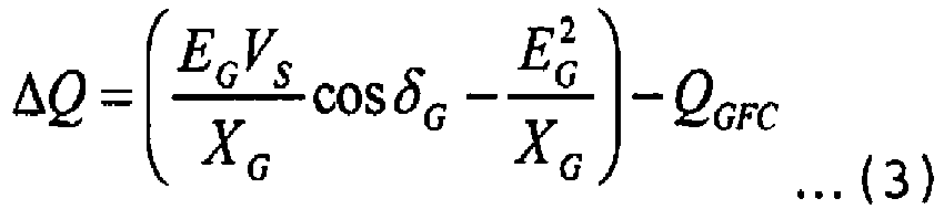
- Here, EG is the induced voltage of the
generator 101, XG is the leakage reactance of thegenerator 101, and cosδG is the power factor angle of the AC/DC converter 106a. Resistance ofgenerator 101 is ignored as being sufficiently smaller than reactance. - The system
terminal control circuit 202 includes a DCvoltage control unit 204, α-β coordinatetransformations phase detection unit 207, d-q coordinatetransformations current control unit 210, an inverse d-q coordinatetransformation 211, an inverse α-β coordinatetransformation 212, a gate pulse generating unit 213, apower calculation unit 215, and a reactivepower control unit 217. - The AC
breaker control circuit 203 receives the active power PGFC, the reactive power QGFC of theFC 104, the generator voltage VG, and the system voltage VS, outputs the circuit switching signal SFLG, and further outputs the bypass breaker operation signal SB and the FC AC breaker operation signals SGFC and SSFC which are closing/opening signals of thebypass breaker 103 and theFC AC breakers -
FIG. 3 is an internal control block diagram illustrating a configuration example of the ACbreaker control circuit 203 illustrated inFIG. 2 . The ACbreaker control circuit 203 includes a circuit switchingdetermination unit 301, amplitude/phase calculation units signal generation unit 304, andsubtractors - The circuit
switching determining unit 301 receives the active power PGFC and the reactive power QGFC of theFC 104, compares the active power PGFC and the reactive power QGFC of theFC 104 with a circuit switching active power Pth and a circuit switching reactive power Qth which are circuit switching threshold values, respectively, and outputs the circuit switching signal SFLG. - In the present embodiment, when the active power PGFC and the reactive power QGFC of the
FC 104 described above respectively exceed the circuit switching threshold values Pth and Qth, it is defined that the circuit switching signal SFLG changes from 0 to 1. A value of the circuit switching signal SFLG is held until a switching reset signal SReset is entered. In the embodiment, a combination of two values of the active power PGFC and the reactive power QGFC is used as the circuit switching threshold values. However, it is not limited thereto and the active power PGFC, the reactive power QGFC, apparent electric power, and the like may be used as the circuit switching threshold values. - The amplitude/
phase calculation units - The circuit breaker closing/opening
signal generation unit 304 receives the active power PGFC, the reactive power QGFC of theFC 104, the circuit switching signal SFLG, the amplitude difference VampDiff, and the phase difference VphaseDiff, and outputs the bypass breaker operation signal SB and the FC AC breaker operation signals SGFC and SSFC which are the closing/opening signals of thebypass breaker 103 and theFC AC breakers - The amplitude difference VampDiff and the phase difference VphaseDiff are respectively compared with an amplitude threshold value VamPth and a phase threshold value Vphaseth which are corresponding synchronization determination threshold values. When the VampDiff and the phase difference VphaseDiff described above are respectively within the synchronization determination threshold values VamPth and Vphaseth, it is determined that the voltage synchronization of the two voltages is secured. Here, values, in which the power fluctuation, when the
bypass breaker 103 is closed, does not affect the stable operation of the device, are used as the synchronization determination threshold values VamPth and Vphaseth. -
FIGS. 4A to 4J respectively illustrate examples of waveforms of parts of a hydropower generation system to which the embodiment is applied. In the example illustrated in the drawings, the circuit switching is performed from an operating state of a FC interconnection operation (thebypass breaker 103 is open and theFC AC breakers bypass breaker 103 is closed and theFC AC breakers - In
FIGS. 4A to 4J , from the top, a vertical axis ofFIG. 4A indicates the system voltage VS, a vertical axis ofFIG. 4B indicates the generator voltage VG, a vertical axis ofFIG. 4C indicates the active power PGFC of theFC 104, a vertical axis ofFIG. 4D indicates the reactive power QGFC, a vertical axis ofFIG. 4E indicates the phase difference VphaseDiff between the system voltage Vs and the generator voltage VG, a vertical axis ofFIG. 4F indicates the amplitude difference VampDiff, a vertical axis ofFIG. 4G indicates an electric power PGB which is transmitted from thegenerator 101 to thepower system 102 via thebypass breaker 103, a vertical axis ofFIG. 4H indicates the circuit switching signal SFLG of the circuit switchingdetermination unit 301, a vertical axis ofFIG. 4I indicates the FC AC breaker operation signals SGFC and SSFC, and a vertical axis ofFIG. 4J indicates the bypass breaker operation signal SB. Further, a horizontal axis indicates a time t. - The breaker operation signals SGFC, SSFC, and SB illustrated in
FIG. 4I and 4J open the corresponding breakers when the value is 0, and close them when the value is 1. Further, in the embodiment, the circuit switching threshold values Pth, Qth are respectively set to the rated values of the active power PGFC and the reactive power QGFC of theFC 104. That is, the circuit switching threshold value Pth=PGFCref_rated is satisfied, the circuit switching threshold value Qth=QGFCref_rated is satisfied. - At the time t0, the hydropower generation system of the embodiment performs the FC interconnection operation with an electric power generated at a low level. At this time, the
bypass breaker 103 is open and no current flows, and thus the power PGB to be transmitted to thepower system 102 is zero. - When the electric power generated by the
generator 101 increases from a time t1 to a time t2, the active power PGFC and the reactive power QGFC of theFC 104 increase in order to transmit the generated electric power to thepower system 102. Then, at the time t2, the active power PGFC and the reactive power QGFC reach the rated values (PGFCref_ratred, QGFCref_rated). At this time, the circuit switching threshold values Pth and Qth are exceeded, and thus the circuit switching signal SFLG of the circuit switchingdetermination unit 301 changes from 0 to 1 and the circuit switching from the FC interconnection operation to the FC bypass operation is executed. - Since the circuit switching signal SFLG becomes 1, as the corrected power commands ΔP and ΔQ of the power command
value adjustment unit 218 illustrated inFIG. 2 , values capable of ensuring voltage synchronization are outputted. The corrected power commands ΔP and ΔQ are added to the PGFCref and the QGFCref of theFC 104 by theadder power control unit 216 and the reactivepower control unit 217 control the active power PGFC and the reactive power QGFC to follow the corrected active power command value PGFCref' and the corrected reactive power command value QGFCref', respectively. - In the period from the time t2 to a time t3, only the command value deviates from the PGFCref_rated, which should be outputted from the
FC 104, by the corrected power command ΔP, and thus the rotation speed and the frequency of thegenerator 101 fluctuate. The system voltage VS is maintained at a substantially constant frequency, and thus the phase difference VphaseDiff varies according to the frequency difference between the generator voltage VG of which the frequency is varied and the system voltage VS. - That is, the instant at which the phase difference VphaseDiff of the generator voltage VG and the system voltage VS crosses the phase threshold value Vphaseth, always occurs within a certain period. Furthermore, the amplitude VGamp of the generator voltage VG can be adjusted by adding the corrected power command ΔQ, and thus the amplitude difference VampDiff with the amplitude VSamp of the system voltage can be controlled within the amplitude threshold value VamPth.
- The power command
value adjustment unit 218 may be provided with a change rate limiter for increasing or decreasing the corrected power commands ΔP and ΔQ on respective ramps as illustrated inFIG. 4 , and may be configured to moderate mechanical stress due to rapid acceleration or sudden deceleration of thegenerator 101 and electrical stress due to voltage sudden change thereof. - When, at the time t3, the amplitude difference VampDiff and the phase difference VphaseDiff of the system voltage VS and the generator voltage VG are within the corresponding synchronization determination threshold values VamPth and Vphaseth, respectively, the bypass breaker operation signal SB is set to 1 and the
bypass breaker 103 is closed. - After it is confirmed that the
bypass breaker 103 is closed, the circuitswitching decision unit 301 outputs the switching reset signal SReset and resets a corrected power command output signal SFLG from 1 to 0. As a result, the corrected power commands ΔP and ΔQ become zero. - Even when the
bypass breaker 103 is closed, VamPth and Vphaseth at which the power fluctuation during the closing of the circuit breaker does not affect the stable operation of the equipment are chosen as described above, and thus the inrush current caused by the closing of thebypass breaker 103 can be suppressed. That is, excessive power fluctuation can be prevented. - In a period from a time t4 to a time t5, the power command
value adjustment unit 218 detects closing (the corrected power command output signal SFLG changes from 1 to 0) of thebypass breaker 103 and outputs the corrected power commands ΔP and ΔQ which respectively make the active power PGFC and the reactive power QGFC of theFC 104 zero. That is, the active power PGFC and the reactive power QGFC of theFC 104 are controlled so that the generated electric power of thegenerator 101 is transmitted to thepower system 102 via thebypass breaker 103, not via theFC 104. - At the time t5, the circuit breaker closing/opening
signal generation unit 304 detects that the active power PGFC and the reactive power QGFC of the AC/DC converter 106a of theFC 104 become substantially zero and opens (FC AC breaker operation signals SGFC and SSFC=0) theFC AC breakers - According to the embodiment, since the
bypass breaker 103 is closed after the voltage synchronization between the system voltage VS and the generator voltage VG is secured in the hydropower generation system, it is possible to prevent excessive power fluctuation. Further, it is not necessary to ensure voltage synchronization by operation of a mechanical part such as a needle valve or a guide vane, so that the circuit switching described above can be performed at high speed. -
FIG. 5 is an overall control block diagram of a hydropower generation system according to a second embodiment. Since the hydropower generation system according to the second embodiment has almost the same configuration and operation as the hydropower generation system according to the first embodiment, the description of the same configuration and operation will not be repeated and the differences will be mainly described hereinafter. - First, in the hydropower generation system according to the first embodiment, the voltage synchronization is secured by adding the corrected power commands ΔP and ΔQ to the generator
terminal control circuit 201. On the other hand, in the hydropower generation system according to the second embodiment, as illustrated inFIG. 5 , the systemterminal control circuit 202 is provided with a power commandvalue adjustment unit 218 and the corrected power command ΔQ is added to the systemterminal control circuit 202. - That is, in the first embodiment, the generator voltage VG is controlled by a corrective reactive power command ΔQ. However, in the second embodiment, the system voltage VS is controlled by a corrective reactive power command ΔQ.
- The corrected power command ΔQ in the embodiment can be calculated using Equation (4) and, for example, it is obtained from a difference between the reactive power for matching the system voltage VS and the generator voltage VG and the reactive power QSFC exchanged between the
power system 102 and theFC 104.
- Here, VS0 is the voltage of the
power system 102, XS is the interactive reactance with thepower system 102, and cosδS is the power factor angle of the AC/DC converter 106b. The resistance is ignored as being sufficiently smaller than the interactive reactance. - According to the embodiment, since the system voltage VS is adjusted by addition of the corrected power command ΔQ, voltage synchronization can be secured without affecting the reactive power control (field current control) of the
generator 101. - The embodiments described above are examples for explaining the invention and it is not intended to limit the invention only to those embodiments. The invention can be implemented in various forms as long as it is not deviated from the point thereof. For example, in the embodiments described above, processing of various programs is described sequentially, but it is not particularly limited thereto. Accordingly, as long as there is no inconsistency in the processing results, the processing order may be switched or configured to parallel operation. In addition, the program including each processing block in the embodiments described above may be stored in a non-transitory storage medium readable by a computer, for example.
- The invention can be broadly applied for a primary-excitation-type hydropower generation system in which a power generator and a power system coupled with a water turbine are interconnected via a frequency converter.
Claims (5)
- A hydropower generation system comprising:
a frequency converter (104) which is provided with two AC output terminals (108a, 108b);a water turbine generator which is interconnected to a power system (102) via the frequency converter (104);a bypass breaker (103) which includes both ends for short-circuiting the two AC output terminals (108a, 108b) in the frequency converter (104);a control device (105) which controls the frequency converter (104) and the bypass breaker (103); anda voltage detector (110a, 110b) which detects two AC voltages at both ends of the bypass breaker (103),the control device (105) being configured to adjust an output voltage of the frequency converter (104) to a direction in which two AC voltage amplitudes at both ends of the bypass breaker (103) coincide with each other and two voltage phases at both ends of the bypass breaker (103) coincide with each other when the bypass breaker (103) is switched from opening to closing, and output a closing command for closing the bypass breaker (103) when an amplitude difference and a phase difference of the two AC voltages at both ends of the bypass breaker (103) are within respective certain values. - The hydropower generation system according to claim 1, wherein
the control device (105) includes a power command correction unit (218) for correcting each power command value (PGFCref; QSFCref; QGFCref) of active power (PGFC) and reactive power (QGFC) exchanged between the frequency converter (104) and a generator (101), and
is configured such that, when the bypass breaker (103) is switched from opening to closing, the frequency converter (104) outputs active power (PGFC) and reactive power (QGFC) such that the amplitude difference and the phase difference between the two AC voltages are zero or within respective certain values. - The hydropower generation system according to claim 2, wherein
the power command correction unit (218) is configured such that, after the bypass breaker (103) is switched from opening to closing, a corrected power command value (ΔP; ΔQ) is adjusted so that each power command value (PGFCref; QSFCref; QGFCref) of the frequency converter (104) becomes zero and generated electric power of the generator (101) is transmitted to the power system (102) via the bypass breaker (103). - The hydropower generation system according to any of claims 2 or claim 3, wherein
the control device (105) includes an output limiter unit for limiting a rate of change of a corrected power command value (ΔP; ΔQ) of the power command correction unit (218) to be within a predetermined value and suppressing sudden power change due to addition of the corrected power command value (ΔP; ΔQ). - The hydropower generation system according to claim 1, wherein
the control device (105) includes a power command correction unit (218) for correcting each power command value of active power (PGFC) exchanged between the frequency converter (104) and a generator (101) and reactive power (QGFC) exchanged between the frequency converter (104) and a power system (102), and
is configured such that, when the bypass breaker (103) is switched from opening to closing, the frequency converter (104) outputs active power and reactive power (QGFC) such that the amplitude difference and the phase difference between the two AC voltages are zero or within respective certain values.
Applications Claiming Priority (1)
| Application Number | Priority Date | Filing Date | Title |
|---|---|---|---|
| JP2017218638A JP7012513B2 (en) | 2017-11-13 | 2017-11-13 | Hydropower system |
Publications (2)
| Publication Number | Publication Date |
|---|---|
| EP3484009A1 true EP3484009A1 (en) | 2019-05-15 |
| EP3484009B1 EP3484009B1 (en) | 2020-12-09 |
Family
ID=63840693
Family Applications (1)
| Application Number | Title | Priority Date | Filing Date |
|---|---|---|---|
| EP18200098.4A Active EP3484009B1 (en) | 2017-11-13 | 2018-10-12 | Hydropower generation system |
Country Status (2)
| Country | Link |
|---|---|
| EP (1) | EP3484009B1 (en) |
| JP (1) | JP7012513B2 (en) |
Cited By (2)
| Publication number | Priority date | Publication date | Assignee | Title |
|---|---|---|---|---|
| CN111550351A (en) * | 2020-05-09 | 2020-08-18 | 西安交通大学 | Double-impeller closed-circuit hydraulic transmission and control ocean current energy generating device and control method thereof |
| WO2021114804A1 (en) * | 2019-12-13 | 2021-06-17 | 华南理工大学广州学院 | Small hydropower station rapid grid connection method considering deviation and trend changes |
Families Citing this family (1)
| Publication number | Priority date | Publication date | Assignee | Title |
|---|---|---|---|---|
| KR102640399B1 (en) * | 2022-05-19 | 2024-02-27 | 파이온일렉트릭 주식회사 | System for hybrid grid forming of synchronous machine and static frequency converter |
Citations (4)
| Publication number | Priority date | Publication date | Assignee | Title |
|---|---|---|---|---|
| US7095597B1 (en) * | 2003-04-30 | 2006-08-22 | Clipper Windpower Technology, Inc. | Distributed static var compensation (DSVC) system for wind and water turbine applications |
| US20090278354A1 (en) * | 2008-05-09 | 2009-11-12 | Hitachi, Ltd. | Wind turbine generator system |
| EP2750285A2 (en) * | 2012-12-27 | 2014-07-02 | GE Energy Power Conversion Technology Ltd | Switching Process and Associated Control Device |
| JP2016158335A (en) | 2015-02-23 | 2016-09-01 | 株式会社東芝 | Variable speed operation control device and hydroelectric power generation system |
Family Cites Families (3)
| Publication number | Priority date | Publication date | Assignee | Title |
|---|---|---|---|---|
| JP3918837B2 (en) | 2004-08-06 | 2007-05-23 | 株式会社日立製作所 | Wind power generator |
| JP4672525B2 (en) | 2005-11-04 | 2011-04-20 | 三菱電機株式会社 | Power quality maintenance control device |
| US8120932B2 (en) | 2008-07-01 | 2012-02-21 | American Superconductor Corporation | Low voltage ride through |
-
2017
- 2017-11-13 JP JP2017218638A patent/JP7012513B2/en active Active
-
2018
- 2018-10-12 EP EP18200098.4A patent/EP3484009B1/en active Active
Patent Citations (4)
| Publication number | Priority date | Publication date | Assignee | Title |
|---|---|---|---|---|
| US7095597B1 (en) * | 2003-04-30 | 2006-08-22 | Clipper Windpower Technology, Inc. | Distributed static var compensation (DSVC) system for wind and water turbine applications |
| US20090278354A1 (en) * | 2008-05-09 | 2009-11-12 | Hitachi, Ltd. | Wind turbine generator system |
| EP2750285A2 (en) * | 2012-12-27 | 2014-07-02 | GE Energy Power Conversion Technology Ltd | Switching Process and Associated Control Device |
| JP2016158335A (en) | 2015-02-23 | 2016-09-01 | 株式会社東芝 | Variable speed operation control device and hydroelectric power generation system |
Cited By (3)
| Publication number | Priority date | Publication date | Assignee | Title |
|---|---|---|---|---|
| WO2021114804A1 (en) * | 2019-12-13 | 2021-06-17 | 华南理工大学广州学院 | Small hydropower station rapid grid connection method considering deviation and trend changes |
| CN111550351A (en) * | 2020-05-09 | 2020-08-18 | 西安交通大学 | Double-impeller closed-circuit hydraulic transmission and control ocean current energy generating device and control method thereof |
| CN111550351B (en) * | 2020-05-09 | 2021-02-02 | 西安交通大学 | Double-impeller closed-circuit hydraulic transmission and control ocean current energy generating device and control method thereof |
Also Published As
| Publication number | Publication date |
|---|---|
| EP3484009B1 (en) | 2020-12-09 |
| JP2019092270A (en) | 2019-06-13 |
| JP7012513B2 (en) | 2022-01-28 |
Similar Documents
| Publication | Publication Date | Title |
|---|---|---|
| US11309789B2 (en) | Inverter and soft-start method for the same | |
| EP4503366A1 (en) | Control system for self-synchronizing voltage source full-power conversion wind turbine generator | |
| EP2043241B1 (en) | Motor Drive Using Flux Adjustment to Control Power Factor | |
| US10014686B2 (en) | Commutation control method and commutation control apparatus | |
| CN107171582B (en) | Signal processing apparatus, filter, control circuit, inverter and converter system | |
| US11183946B2 (en) | Integrated rectifier-generator system for AC-to-DC conversion | |
| CN102150356A (en) | Direct power control with component separation | |
| CN114258620B (en) | A current control method and system for voltage asymmetry fault | |
| EP3484009B1 (en) | Hydropower generation system | |
| US11223310B2 (en) | Variable speed generator/motor device | |
| EP2916442B1 (en) | A voltage source converter | |
| CN115102149A (en) | Overcurrent suppression system and method for network type converter | |
| CN116995730A (en) | A DC side voltage reference value setting method, device, storage medium and equipment | |
| CN103532469B (en) | Mesohigh synchronous machine self-control frequency-variable soft start automatic presynchronization grid-connected control method | |
| US20250226657A1 (en) | Power supply system and grid-forming control method | |
| Narula et al. | Tuning and evaluation of grid-forming converters for grid-support | |
| CN106451549A (en) | Method for excitation-control-based doubly-fed induction generator fault ride-through assessment under condition of symmetrical faults | |
| CN109256805B (en) | Virtual synchronous generator power decoupling method based on single rotation angle virtual power | |
| CN120546001A (en) | A method and system for limiting current of a virtual synchronous generator after a power grid fault | |
| CN111884229B (en) | Asynchronous and synchronous control method and system for back-to-back flexible direct current power transmission system | |
| CN108322113A (en) | A kind of switched reluctance motor system method for controlling power balance | |
| JP6095561B2 (en) | Motor drive control device | |
| JPH08126400A (en) | Vector controller for induction motor | |
| EP4629470A1 (en) | Current limiting control method and apparatus for grid-forming converter, converter, and storage medium | |
| CN110535376A (en) | A speed control method in pulse commutation stage of static frequency converter |
Legal Events
| Date | Code | Title | Description |
|---|---|---|---|
| PUAI | Public reference made under article 153(3) epc to a published international application that has entered the european phase |
Free format text: ORIGINAL CODE: 0009012 |
|
| STAA | Information on the status of an ep patent application or granted ep patent |
Free format text: STATUS: REQUEST FOR EXAMINATION WAS MADE |
|
| 17P | Request for examination filed |
Effective date: 20190311 |
|
| AK | Designated contracting states |
Kind code of ref document: A1 Designated state(s): AL AT BE BG CH CY CZ DE DK EE ES FI FR GB GR HR HU IE IS IT LI LT LU LV MC MK MT NL NO PL PT RO RS SE SI SK SM TR |
|
| AX | Request for extension of the european patent |
Extension state: BA ME |
|
| GRAP | Despatch of communication of intention to grant a patent |
Free format text: ORIGINAL CODE: EPIDOSNIGR1 |
|
| STAA | Information on the status of an ep patent application or granted ep patent |
Free format text: STATUS: GRANT OF PATENT IS INTENDED |
|
| RIC1 | Information provided on ipc code assigned before grant |
Ipc: H02P 9/10 20060101ALI20200422BHEP Ipc: H02P 9/00 20060101ALI20200422BHEP Ipc: F03B 15/00 20060101ALI20200422BHEP Ipc: F03B 13/00 20060101ALI20200422BHEP Ipc: H02J 3/40 20060101AFI20200422BHEP |
|
| INTG | Intention to grant announced |
Effective date: 20200518 |
|
| GRAS | Grant fee paid |
Free format text: ORIGINAL CODE: EPIDOSNIGR3 |
|
| GRAA | (expected) grant |
Free format text: ORIGINAL CODE: 0009210 |
|
| STAA | Information on the status of an ep patent application or granted ep patent |
Free format text: STATUS: THE PATENT HAS BEEN GRANTED |
|
| AK | Designated contracting states |
Kind code of ref document: B1 Designated state(s): AL AT BE BG CH CY CZ DE DK EE ES FI FR GB GR HR HU IE IS IT LI LT LU LV MC MK MT NL NO PL PT RO RS SE SI SK SM TR |
|
| REG | Reference to a national code |
Ref country code: GB Ref legal event code: FG4D |
|
| REG | Reference to a national code |
Ref country code: AT Ref legal event code: REF Ref document number: 1344375 Country of ref document: AT Kind code of ref document: T Effective date: 20201215 Ref country code: CH Ref legal event code: EP |
|
| REG | Reference to a national code |
Ref country code: DE Ref legal event code: R096 Ref document number: 602018010599 Country of ref document: DE |
|
| REG | Reference to a national code |
Ref country code: IE Ref legal event code: FG4D |
|
| PG25 | Lapsed in a contracting state [announced via postgrant information from national office to epo] |
Ref country code: GR Free format text: LAPSE BECAUSE OF FAILURE TO SUBMIT A TRANSLATION OF THE DESCRIPTION OR TO PAY THE FEE WITHIN THE PRESCRIBED TIME-LIMIT Effective date: 20210310 Ref country code: NO Free format text: LAPSE BECAUSE OF FAILURE TO SUBMIT A TRANSLATION OF THE DESCRIPTION OR TO PAY THE FEE WITHIN THE PRESCRIBED TIME-LIMIT Effective date: 20210309 Ref country code: FI Free format text: LAPSE BECAUSE OF FAILURE TO SUBMIT A TRANSLATION OF THE DESCRIPTION OR TO PAY THE FEE WITHIN THE PRESCRIBED TIME-LIMIT Effective date: 20201209 Ref country code: RS Free format text: LAPSE BECAUSE OF FAILURE TO SUBMIT A TRANSLATION OF THE DESCRIPTION OR TO PAY THE FEE WITHIN THE PRESCRIBED TIME-LIMIT Effective date: 20201209 |
|
| REG | Reference to a national code |
Ref country code: AT Ref legal event code: MK05 Ref document number: 1344375 Country of ref document: AT Kind code of ref document: T Effective date: 20201209 |
|
| PG25 | Lapsed in a contracting state [announced via postgrant information from national office to epo] |
Ref country code: SE Free format text: LAPSE BECAUSE OF FAILURE TO SUBMIT A TRANSLATION OF THE DESCRIPTION OR TO PAY THE FEE WITHIN THE PRESCRIBED TIME-LIMIT Effective date: 20201209 Ref country code: LV Free format text: LAPSE BECAUSE OF FAILURE TO SUBMIT A TRANSLATION OF THE DESCRIPTION OR TO PAY THE FEE WITHIN THE PRESCRIBED TIME-LIMIT Effective date: 20201209 Ref country code: BG Free format text: LAPSE BECAUSE OF FAILURE TO SUBMIT A TRANSLATION OF THE DESCRIPTION OR TO PAY THE FEE WITHIN THE PRESCRIBED TIME-LIMIT Effective date: 20210309 |
|
| REG | Reference to a national code |
Ref country code: NL Ref legal event code: MP Effective date: 20201209 |
|
| PG25 | Lapsed in a contracting state [announced via postgrant information from national office to epo] |
Ref country code: NL Free format text: LAPSE BECAUSE OF FAILURE TO SUBMIT A TRANSLATION OF THE DESCRIPTION OR TO PAY THE FEE WITHIN THE PRESCRIBED TIME-LIMIT Effective date: 20201209 Ref country code: HR Free format text: LAPSE BECAUSE OF FAILURE TO SUBMIT A TRANSLATION OF THE DESCRIPTION OR TO PAY THE FEE WITHIN THE PRESCRIBED TIME-LIMIT Effective date: 20201209 |
|
| REG | Reference to a national code |
Ref country code: LT Ref legal event code: MG9D |
|
| PG25 | Lapsed in a contracting state [announced via postgrant information from national office to epo] |
Ref country code: CZ Free format text: LAPSE BECAUSE OF FAILURE TO SUBMIT A TRANSLATION OF THE DESCRIPTION OR TO PAY THE FEE WITHIN THE PRESCRIBED TIME-LIMIT Effective date: 20201209 Ref country code: EE Free format text: LAPSE BECAUSE OF FAILURE TO SUBMIT A TRANSLATION OF THE DESCRIPTION OR TO PAY THE FEE WITHIN THE PRESCRIBED TIME-LIMIT Effective date: 20201209 Ref country code: SM Free format text: LAPSE BECAUSE OF FAILURE TO SUBMIT A TRANSLATION OF THE DESCRIPTION OR TO PAY THE FEE WITHIN THE PRESCRIBED TIME-LIMIT Effective date: 20201209 Ref country code: RO Free format text: LAPSE BECAUSE OF FAILURE TO SUBMIT A TRANSLATION OF THE DESCRIPTION OR TO PAY THE FEE WITHIN THE PRESCRIBED TIME-LIMIT Effective date: 20201209 Ref country code: SK Free format text: LAPSE BECAUSE OF FAILURE TO SUBMIT A TRANSLATION OF THE DESCRIPTION OR TO PAY THE FEE WITHIN THE PRESCRIBED TIME-LIMIT Effective date: 20201209 Ref country code: PT Free format text: LAPSE BECAUSE OF FAILURE TO SUBMIT A TRANSLATION OF THE DESCRIPTION OR TO PAY THE FEE WITHIN THE PRESCRIBED TIME-LIMIT Effective date: 20210409 Ref country code: LT Free format text: LAPSE BECAUSE OF FAILURE TO SUBMIT A TRANSLATION OF THE DESCRIPTION OR TO PAY THE FEE WITHIN THE PRESCRIBED TIME-LIMIT Effective date: 20201209 |
|
| PG25 | Lapsed in a contracting state [announced via postgrant information from national office to epo] |
Ref country code: PL Free format text: LAPSE BECAUSE OF FAILURE TO SUBMIT A TRANSLATION OF THE DESCRIPTION OR TO PAY THE FEE WITHIN THE PRESCRIBED TIME-LIMIT Effective date: 20201209 Ref country code: AT Free format text: LAPSE BECAUSE OF FAILURE TO SUBMIT A TRANSLATION OF THE DESCRIPTION OR TO PAY THE FEE WITHIN THE PRESCRIBED TIME-LIMIT Effective date: 20201209 |
|
| REG | Reference to a national code |
Ref country code: DE Ref legal event code: R097 Ref document number: 602018010599 Country of ref document: DE |
|
| PG25 | Lapsed in a contracting state [announced via postgrant information from national office to epo] |
Ref country code: IS Free format text: LAPSE BECAUSE OF FAILURE TO SUBMIT A TRANSLATION OF THE DESCRIPTION OR TO PAY THE FEE WITHIN THE PRESCRIBED TIME-LIMIT Effective date: 20210409 |
|
| PLBE | No opposition filed within time limit |
Free format text: ORIGINAL CODE: 0009261 |
|
| STAA | Information on the status of an ep patent application or granted ep patent |
Free format text: STATUS: NO OPPOSITION FILED WITHIN TIME LIMIT |
|
| PG25 | Lapsed in a contracting state [announced via postgrant information from national office to epo] |
Ref country code: IT Free format text: LAPSE BECAUSE OF FAILURE TO SUBMIT A TRANSLATION OF THE DESCRIPTION OR TO PAY THE FEE WITHIN THE PRESCRIBED TIME-LIMIT Effective date: 20201209 Ref country code: AL Free format text: LAPSE BECAUSE OF FAILURE TO SUBMIT A TRANSLATION OF THE DESCRIPTION OR TO PAY THE FEE WITHIN THE PRESCRIBED TIME-LIMIT Effective date: 20201209 |
|
| 26N | No opposition filed |
Effective date: 20210910 |
|
| PG25 | Lapsed in a contracting state [announced via postgrant information from national office to epo] |
Ref country code: SI Free format text: LAPSE BECAUSE OF FAILURE TO SUBMIT A TRANSLATION OF THE DESCRIPTION OR TO PAY THE FEE WITHIN THE PRESCRIBED TIME-LIMIT Effective date: 20201209 Ref country code: DK Free format text: LAPSE BECAUSE OF FAILURE TO SUBMIT A TRANSLATION OF THE DESCRIPTION OR TO PAY THE FEE WITHIN THE PRESCRIBED TIME-LIMIT Effective date: 20201209 |
|
| PG25 | Lapsed in a contracting state [announced via postgrant information from national office to epo] |
Ref country code: ES Free format text: LAPSE BECAUSE OF FAILURE TO SUBMIT A TRANSLATION OF THE DESCRIPTION OR TO PAY THE FEE WITHIN THE PRESCRIBED TIME-LIMIT Effective date: 20201209 |
|
| PG25 | Lapsed in a contracting state [announced via postgrant information from national office to epo] |
Ref country code: IS Free format text: LAPSE BECAUSE OF FAILURE TO SUBMIT A TRANSLATION OF THE DESCRIPTION OR TO PAY THE FEE WITHIN THE PRESCRIBED TIME-LIMIT Effective date: 20210409 |
|
| REG | Reference to a national code |
Ref country code: BE Ref legal event code: MM Effective date: 20211031 |
|
| PG25 | Lapsed in a contracting state [announced via postgrant information from national office to epo] |
Ref country code: MC Free format text: LAPSE BECAUSE OF FAILURE TO SUBMIT A TRANSLATION OF THE DESCRIPTION OR TO PAY THE FEE WITHIN THE PRESCRIBED TIME-LIMIT Effective date: 20201209 |
|
| PG25 | Lapsed in a contracting state [announced via postgrant information from national office to epo] |
Ref country code: LU Free format text: LAPSE BECAUSE OF NON-PAYMENT OF DUE FEES Effective date: 20211012 Ref country code: BE Free format text: LAPSE BECAUSE OF NON-PAYMENT OF DUE FEES Effective date: 20211031 |
|
| PG25 | Lapsed in a contracting state [announced via postgrant information from national office to epo] |
Ref country code: FR Free format text: LAPSE BECAUSE OF NON-PAYMENT OF DUE FEES Effective date: 20211031 |
|
| PG25 | Lapsed in a contracting state [announced via postgrant information from national office to epo] |
Ref country code: IE Free format text: LAPSE BECAUSE OF NON-PAYMENT OF DUE FEES Effective date: 20211012 |
|
| GBPC | Gb: european patent ceased through non-payment of renewal fee |
Effective date: 20221012 |
|
| PG25 | Lapsed in a contracting state [announced via postgrant information from national office to epo] |
Ref country code: CY Free format text: LAPSE BECAUSE OF FAILURE TO SUBMIT A TRANSLATION OF THE DESCRIPTION OR TO PAY THE FEE WITHIN THE PRESCRIBED TIME-LIMIT Effective date: 20201209 |
|
| PG25 | Lapsed in a contracting state [announced via postgrant information from national office to epo] |
Ref country code: HU Free format text: LAPSE BECAUSE OF FAILURE TO SUBMIT A TRANSLATION OF THE DESCRIPTION OR TO PAY THE FEE WITHIN THE PRESCRIBED TIME-LIMIT; INVALID AB INITIO Effective date: 20181012 |
|
| PG25 | Lapsed in a contracting state [announced via postgrant information from national office to epo] |
Ref country code: GB Free format text: LAPSE BECAUSE OF NON-PAYMENT OF DUE FEES Effective date: 20221012 |
|
| PG25 | Lapsed in a contracting state [announced via postgrant information from national office to epo] |
Ref country code: MK Free format text: LAPSE BECAUSE OF FAILURE TO SUBMIT A TRANSLATION OF THE DESCRIPTION OR TO PAY THE FEE WITHIN THE PRESCRIBED TIME-LIMIT Effective date: 20201209 |
|
| PG25 | Lapsed in a contracting state [announced via postgrant information from national office to epo] |
Ref country code: MT Free format text: LAPSE BECAUSE OF FAILURE TO SUBMIT A TRANSLATION OF THE DESCRIPTION OR TO PAY THE FEE WITHIN THE PRESCRIBED TIME-LIMIT Effective date: 20201209 |
|
| REG | Reference to a national code |
Ref country code: CH Ref legal event code: U11 Free format text: ST27 STATUS EVENT CODE: U-0-0-U10-U11 (AS PROVIDED BY THE NATIONAL OFFICE) Effective date: 20251101 |
|
| PG25 | Lapsed in a contracting state [announced via postgrant information from national office to epo] |
Ref country code: TR Free format text: LAPSE BECAUSE OF FAILURE TO SUBMIT A TRANSLATION OF THE DESCRIPTION OR TO PAY THE FEE WITHIN THE PRESCRIBED TIME-LIMIT Effective date: 20201209 |
|
| PGFP | Annual fee paid to national office [announced via postgrant information from national office to epo] |
Ref country code: DE Payment date: 20250923 Year of fee payment: 8 |
|
| PGFP | Annual fee paid to national office [announced via postgrant information from national office to epo] |
Ref country code: CH Payment date: 20251101 Year of fee payment: 8 |