EP3483947B1 - Battery - Google Patents
Battery Download PDFInfo
- Publication number
- EP3483947B1 EP3483947B1 EP18180776.9A EP18180776A EP3483947B1 EP 3483947 B1 EP3483947 B1 EP 3483947B1 EP 18180776 A EP18180776 A EP 18180776A EP 3483947 B1 EP3483947 B1 EP 3483947B1
- Authority
- EP
- European Patent Office
- Prior art keywords
- battery
- case
- battery case
- heat resistant
- resistant sheet
- Prior art date
- Legal status (The legal status is an assumption and is not a legal conclusion. Google has not performed a legal analysis and makes no representation as to the accuracy of the status listed.)
- Active
Links
Images



Classifications
-
- H—ELECTRICITY
- H01—ELECTRIC ELEMENTS
- H01M—PROCESSES OR MEANS, e.g. BATTERIES, FOR THE DIRECT CONVERSION OF CHEMICAL ENERGY INTO ELECTRICAL ENERGY
- H01M50/00—Constructional details or processes of manufacture of the non-active parts of electrochemical cells other than fuel cells, e.g. hybrid cells
- H01M50/20—Mountings; Secondary casings or frames; Racks, modules or packs; Suspension devices; Shock absorbers; Transport or carrying devices; Holders
- H01M50/233—Mountings; Secondary casings or frames; Racks, modules or packs; Suspension devices; Shock absorbers; Transport or carrying devices; Holders characterised by physical properties of casings or racks, e.g. dimensions
- H01M50/24—Mountings; Secondary casings or frames; Racks, modules or packs; Suspension devices; Shock absorbers; Transport or carrying devices; Holders characterised by physical properties of casings or racks, e.g. dimensions adapted for protecting batteries from their environment, e.g. from corrosion
-
- H—ELECTRICITY
- H01—ELECTRIC ELEMENTS
- H01M—PROCESSES OR MEANS, e.g. BATTERIES, FOR THE DIRECT CONVERSION OF CHEMICAL ENERGY INTO ELECTRICAL ENERGY
- H01M10/00—Secondary cells; Manufacture thereof
- H01M10/60—Heating or cooling; Temperature control
- H01M10/65—Means for temperature control structurally associated with the cells
- H01M10/658—Means for temperature control structurally associated with the cells by thermal insulation or shielding
-
- H—ELECTRICITY
- H01—ELECTRIC ELEMENTS
- H01M—PROCESSES OR MEANS, e.g. BATTERIES, FOR THE DIRECT CONVERSION OF CHEMICAL ENERGY INTO ELECTRICAL ENERGY
- H01M50/00—Constructional details or processes of manufacture of the non-active parts of electrochemical cells other than fuel cells, e.g. hybrid cells
- H01M50/20—Mountings; Secondary casings or frames; Racks, modules or packs; Suspension devices; Shock absorbers; Transport or carrying devices; Holders
- H01M50/271—Lids or covers for the racks or secondary casings
-
- H—ELECTRICITY
- H01—ELECTRIC ELEMENTS
- H01M—PROCESSES OR MEANS, e.g. BATTERIES, FOR THE DIRECT CONVERSION OF CHEMICAL ENERGY INTO ELECTRICAL ENERGY
- H01M2200/00—Safety devices for primary or secondary batteries
-
- H—ELECTRICITY
- H01—ELECTRIC ELEMENTS
- H01M—PROCESSES OR MEANS, e.g. BATTERIES, FOR THE DIRECT CONVERSION OF CHEMICAL ENERGY INTO ELECTRICAL ENERGY
- H01M50/00—Constructional details or processes of manufacture of the non-active parts of electrochemical cells other than fuel cells, e.g. hybrid cells
- H01M50/20—Mountings; Secondary casings or frames; Racks, modules or packs; Suspension devices; Shock absorbers; Transport or carrying devices; Holders
- H01M50/204—Racks, modules or packs for multiple batteries or multiple cells
- H01M50/207—Racks, modules or packs for multiple batteries or multiple cells characterised by their shape
- H01M50/209—Racks, modules or packs for multiple batteries or multiple cells characterised by their shape adapted for prismatic or rectangular cells
-
- Y—GENERAL TAGGING OF NEW TECHNOLOGICAL DEVELOPMENTS; GENERAL TAGGING OF CROSS-SECTIONAL TECHNOLOGIES SPANNING OVER SEVERAL SECTIONS OF THE IPC; TECHNICAL SUBJECTS COVERED BY FORMER USPC CROSS-REFERENCE ART COLLECTIONS [XRACs] AND DIGESTS
- Y02—TECHNOLOGIES OR APPLICATIONS FOR MITIGATION OR ADAPTATION AGAINST CLIMATE CHANGE
- Y02E—REDUCTION OF GREENHOUSE GAS [GHG] EMISSIONS, RELATED TO ENERGY GENERATION, TRANSMISSION OR DISTRIBUTION
- Y02E60/00—Enabling technologies; Technologies with a potential or indirect contribution to GHG emissions mitigation
- Y02E60/10—Energy storage using batteries
Definitions
- Embodiments described herein relate generally to a battery, such as a battery pack.
- a battery module which is an aggregation of a plurality of battery cells, is housed in a rectangular box-shaped battery case of a battery. If this battery is dropped, crushed, etc., the battery case or a battery cell inside the battery case is broken, and a short circuit is generated inside the battery cell housed in the battery case. Due to this, an electrolyte solution of the battery cell is expelled as a high temperature combustible gas. Then, the expelled combustible gas may be ignited by an electric spark generated due to a short circuit in the battery case. Preventing such ignition is necessary for safety of the battery.
- EP 2 299 353 A1 discloses a battery module forming the basis for the preamble of claim 1. Another battery module is known from US 2017/0271635 A1 .
- a battery includes the features of claim 1.
- FIGS. 1 to 5 depict an embodiment.
- FIG. 1 is a perspective view depicting a general configuration of the entire battery according to the embodiment.
- FIG. 2 is a longitudinal cross sectional view depicting an internal structure of the battery of FIG. 1 .
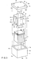
- FIG. 3 is an exploded perspective view of the battery of FIG. 1 .
- FIG. 4 is a cross sectional view depicting a mounting state of a heat resistant sheet incorporated into the battery of FIG. 1 .
- FIG. 5 is a cross sectional view depicting a state in which a battery module in the battery of FIG. 4 is expanded.
- a battery case 11 of a battery 11A of the present embodiment comprises an upper case 12, a lower case 13, and a pressure relief portion 16.
- the lower case 13 is a rectangular box-shaped housing in which an upper surface opening 13a is formed.
- This lower case 13 comprises a bottom plate 13b shaped like a rectangular flat plate, and side wall portions 13c, 13d, 13e, and 13f providing four surfaces including a front surface, a rear surface, a right surface, and a left surface.
- a battery module 15 which is an aggregation of a plurality of battery cells 14, is housed as shown in FIG. 3 .
- an electrode main body (coil) that is spirally wound, an electrolyte solution, etc. are housed in a cell can, a laminate film, etc.
- a control substrate 17, a bus bar, other structural members, etc. are arranged on an upper surface side of the battery module 15.
- the upper case 12 is a rectangular box-shaped housing in which a lower surface opening 12a is formed.
- This upper case 12 comprises a top plate 12b, and side wall portions 12c, 12d, 12e, and 12f providing four surfaces including a front surface, a rear surface, a right surface, and a left surface.
- the upper case 12 is provided on its upper surface with a positive electrode terminal 18, a negative electrode terminal 19, the pressure relief portion 16, etc. As shown in FIG. 2 , the positive electrode terminal 18 is connected to a positive electrode tab 20 of the battery module 15. The negative electrode terminal 19 is connected to a negative electrode tab 21 of the battery module 15.
- the pressure relief portion 16 is formed by a waterproof vent filter allowing the air inside the battery case 11 and the air outside the battery case 11 to flow out from and into the battery case 11, respectively, while keeping the inner portion of the battery case 11 water tight.
- This waterproof vent filter comprises, for example, a porous PTFE film.
- the heat resistant sheet 22 is arranged between the battery case 11 and the battery module 15.
- This heat resistant sheet 22 is formed from, for example, polyimide resin or Teflon (registered trademark) resin.
- the heat resistant sheet 22 provides an air infiltration prevention sheet preventing air from infiltrating from the outside into the inside of the battery case 11.
- the heat resistant sheet 22 is made by combining four pieces of L-shaped members 23 in a rectangular frame shape in a state of being partially overlapped side by side, the four pieces of L-shaped members 23 each being made by bending a piece of a sheet main body 22a into an L shape. In other words, a part of each of two L-shaped members 23 adjacent in a circumferential direction of the heat resistant sheet 22 is overlapped with each other.
- the four pieces of L-shaped members 23 combined in a rectangular frame shape are arranged in a state of covering the entire side surface of the inner wall surface of the battery case 11.
- the side surface mentioned herein is a surface provided by the side wall portions 13c, 13d, 13e, and 13f and the side wall portions 12c, 12d, 12e, and 12f among the inner wall surfaces providing an internal space of the battery 11.
- each of the L-shaped members 23 in several places of the surface of each of the L-shaped members 23, for example, one surface side of a double-sided tape 24 with relatively weak adhesion is adhered.
- the other side of these double-sided tapes 24 is adhered on the inner wall surface of the battery case 11.
- the heat resistant sheet 22 is fixed to the inner wall surface of the battery case 11 by relatively weak force.
- an overlapped portion 25 of the adjacent L-shaped members 23 is not joined with each other, and is kept in a mutually freely movable state.
- a double-sided tape 24 is not adhered on mutually opposed surfaces of two mutually opposed portions 25.
- the heat resistant sheet 22 is arranged in a state of covering at least a joint portion of a lateral side joining between the lower case 13 and the upper case 12 of the battery case 11, and a joint portion of a longitudinal side joining between adjacent side surfaces of the battery case 11.
- the joint portion of the lateral side is composed of surfaces of a lower end surface of the upper case 12 and an upper end surface of the lower case 13 which are in contact with each other.
- FIGS. 6A, 6B, 6C, and 6D are explanatory drawings for explaining the manner of cracking of the battery case 11 of the battery 11A.
- FIGS. 6A to 6D general configurations of the upper case 12 and the lower case 13 are shown, and the pressure relief portion 16, the positive electrode terminal 18, and the negative electrode terminal 19 are omitted.
- FIG. 6A shows a state in which forces F1 and F2 of pressing from the up and down directions are applied to the battery 11A.
- FIG. 6B shows a state in which the battery case 11 is partially destroyed due to the forces F1 and F2 shown in FIG. 6A .
- FIG. 6C shows a state in which the battery 11 is pressed from a lateral direction against a wall 3 provided in a vertical direction, and a force F3 of pressing from the lateral direction is applied to the battery 11.
- FIG. 6D shows a state in which the battery case 11 is partially destroyed due to the force F3 shown in FIG. 6C .
- a crack is generated in a longitudinal side of a joint portion 2d, etc. between two circumferentially adjacent side walls 2c of the four side wall portions 2c of the battery case 11 and a lateral side of a joint portion 2e, etc. between the upper case 2a and the lower case 2b, and a large crack 2f is generated.
- One of the four side wall portions 2c of the battery case 11 is composed of the side wall portion 12c of the upper case 12 and the side wall portion 13c of the lower case 13.
- Another side wall portion 2c is composed of the side wall portion 12d and the side wall portion 13d.
- Another side wall portion 2c is composed of the side wall portion 12e and the side wall portion 13e.
- Another side wall portion 2c is composed of the side wall portion 12f and the side wall portion 13f.
- a crack is generated in a longitudinal side of a joint portion 2d, etc. between adjacent side walls 2c of the battery case 11 and a lateral side of a joint portion 2e, etc. between the upper case 12 and the lower case 13, and the large crack 2f is generated.
- the joint portion 2d is a corner between two adjacent side wall portions 2c.
- the pressing forces F1 and F2 from the up and down directions are applied to the battery 11, and the pressing force F3 from a lateral direction of pressing the battery 11 against the wall 3 may be applied to the battery 11 as shown in FIG. 6C .
- a crack may be generated in a longitudinal side of the joint portion 2d, etc. between adjacent side walls 2c of the battery case 11 and a lateral side of the joint portion 2e, etc. between the upper case 12 and the lower case 13, and the large crack 2f may be generated.
- the combustible gas in the battery cell 14 is expelled to the outside of the battery cell 14 from a safety valve (not shown) of the battery cell 14. Accordingly, the internal pressure of the battery case 11 increases, and by this pressure, the heat resistant sheet 22 is retained in a state of being pressed against an inner surface of the battery case 11.
- the heat resistant sheet 22 is fixed to the inner wall surface of the battery case 11 by the double-sided tape 24 with relatively weak force. For this reason, as shown in FIGS. 6B and 6D , even if the crack 2f is generated in the battery case 11, the heat resistant sheet 22 slides with respect to the battery case 11 as indicated by arrows in FIG. 5 , or the heat resistant sheet 22 itself extends.
- the heat resistant sheet 22 can be prevented from being torn along with the generation of the crack 2f of the battery case 11, the crack 2f of the battery case 11 can be blocked by the heat resistant sheet 22.
- the heat resistant sheet 22 is configured to be fixed to the inner wall surface of the battery case 11, it is possible to carry out an operation of fixing the heat resistant sheet 22 to the inner wall surface of the battery case 11 prior to assembling the battery module 15 to the battery case 11.
- the mounting operation of the heat resistant sheet 22 can be easily carried out.
Landscapes
- Chemical & Material Sciences (AREA)
- Chemical Kinetics & Catalysis (AREA)
- Electrochemistry (AREA)
- General Chemical & Material Sciences (AREA)
- Engineering & Computer Science (AREA)
- Manufacturing & Machinery (AREA)
- Battery Mounting, Suspending (AREA)
- Secondary Cells (AREA)
Description
- Embodiments described herein relate generally to a battery, such as a battery pack.
- A battery module, which is an aggregation of a plurality of battery cells, is housed in a rectangular box-shaped battery case of a battery. If this battery is dropped, crushed, etc., the battery case or a battery cell inside the battery case is broken, and a short circuit is generated inside the battery cell housed in the battery case. Due to this, an electrolyte solution of the battery cell is expelled as a high temperature combustible gas. Then, the expelled combustible gas may be ignited by an electric spark generated due to a short circuit in the battery case. Preventing such ignition is necessary for safety of the battery.
-
EP 2 299 353 A1 discloses a battery module forming the basis for the preamble ofclaim 1. Another battery module is known fromUS 2017/0271635 A1 . -
-
FIG. 1 is a perspective view depicting a general configuration of the entire battery according to an embodiment. -
FIG. 2 is a longitudinal cross sectional view depicting an internal structure of the battery ofFIG. 1 . -
FIG. 3 is an exploded perspective view of the battery ofFIG. 1 . -
FIG. 4 is a cross sectional view depicting a mounting state of a heat resistant sheet incorporated into the battery. -
FIG. 5 is a cross sectional view depicting a state in which a battery module in the battery ofFIG. 4 is expanded. -
FIG. 6A is an explanatory drawing for explaining a manner of cracking of a battery case of a battery. -
FIG. 6B is an explanatory drawing for explaining a manner of cracking of a battery case of a battery. -
FIG. 6C is an explanatory drawing for explaining a manner of cracking of a battery case of a battery. -
FIG. 6D is an explanatory drawing for explaining a manner of cracking of a battery case of a battery. - According to embodiments, a battery includes the features of
claim 1. -
FIGS. 1 to 5 depict an embodiment.FIG. 1 is a perspective view depicting a general configuration of the entire battery according to the embodiment.FIG. 2 is a longitudinal cross sectional view depicting an internal structure of the battery ofFIG. 1 .FIG. 3 is an exploded perspective view of the battery ofFIG. 1 .FIG. 4 is a cross sectional view depicting a mounting state of a heat resistant sheet incorporated into the battery ofFIG. 1 .FIG. 5 is a cross sectional view depicting a state in which a battery module in the battery ofFIG. 4 is expanded. - A
battery case 11 of abattery 11A of the present embodiment comprises anupper case 12, alower case 13, and apressure relief portion 16. As shown inFIG. 2 , thelower case 13 is a rectangular box-shaped housing in which an upper surface opening 13a is formed. Thislower case 13 comprises abottom plate 13b shaped like a rectangular flat plate, andside wall portions - Inside the
lower case 13, abattery module 15, which is an aggregation of a plurality ofbattery cells 14, is housed as shown inFIG. 3 . In thebattery cell 14, for example, an electrode main body (coil) that is spirally wound, an electrolyte solution, etc. are housed in a cell can, a laminate film, etc. On an upper surface side of thebattery module 15, acontrol substrate 17, a bus bar, other structural members, etc. are arranged. - The
upper case 12 is a rectangular box-shaped housing in which a lower surface opening 12a is formed. Thisupper case 12 comprises atop plate 12b, andside wall portions lower case 13, in other words, an end portion on the upper surface opening 13a side, and a lower end portion of theupper case 12, in other words, an end portion on the lower surface opening 12a side, are abutted, theupper case 12 and thelower case 13 are fixed by a screw. Thereby, theupper case 12 and thelower case 13 are joined. At this time, between thelower case 13 and theupper case 12 is sealed by a packing (not shown), and an inner portion of thebattery case 11 is sealed. - The
upper case 12 is provided on its upper surface with apositive electrode terminal 18, anegative electrode terminal 19, thepressure relief portion 16, etc. As shown inFIG. 2 , thepositive electrode terminal 18 is connected to apositive electrode tab 20 of thebattery module 15. Thenegative electrode terminal 19 is connected to anegative electrode tab 21 of thebattery module 15. - The
pressure relief portion 16 is formed by a waterproof vent filter allowing the air inside thebattery case 11 and the air outside thebattery case 11 to flow out from and into thebattery case 11, respectively, while keeping the inner portion of thebattery case 11 water tight. This waterproof vent filter comprises, for example, a porous PTFE film. Then, thepressure relief portion 16 is configured, when the internal pressure of thebattery case 11 changes as a result of a change in surrounding atmospheric pressure, a rise in temperature, etc., to allow the air inside thebattery case 11 and the air outside thebattery case 11 to flow out from and into thebattery case 11, in other words, to be exchanged, with thebattery case 11 kept water tight. This inhibits a difference in pressure between the inside and outside of thebattery case 11. - In addition, in the present embodiment, the heat
resistant sheet 22 is arranged between thebattery case 11 and thebattery module 15. This heatresistant sheet 22 is formed from, for example, polyimide resin or Teflon (registered trademark) resin. The heatresistant sheet 22 provides an air infiltration prevention sheet preventing air from infiltrating from the outside into the inside of thebattery case 11. - The heat
resistant sheet 22 is made by combining four pieces of L-shaped members 23 in a rectangular frame shape in a state of being partially overlapped side by side, the four pieces of L-shaped members 23 each being made by bending a piece of a sheetmain body 22a into an L shape. In other words, a part of each of two L-shaped members 23 adjacent in a circumferential direction of the heatresistant sheet 22 is overlapped with each other. In the present embodiment, the four pieces of L-shaped members 23 combined in a rectangular frame shape are arranged in a state of covering the entire side surface of the inner wall surface of thebattery case 11. - Note that the side surface mentioned herein is a surface provided by the
side wall portions side wall portions battery 11. - In the present embodiment, in several places of the surface of each of the L-
shaped members 23, for example, one surface side of a double-sided tape 24 with relatively weak adhesion is adhered. The other side of these double-sided tapes 24 is adhered on the inner wall surface of thebattery case 11. Thereby, the heatresistant sheet 22 is fixed to the inner wall surface of thebattery case 11 by relatively weak force. - As shown in
FIG. 4 , an overlappedportion 25 of the adjacent L-shaped members 23 is not joined with each other, and is kept in a mutually freely movable state. In other words, a double-sided tape 24 is not adhered on mutually opposed surfaces of two mutually opposedportions 25. - Furthermore, the heat
resistant sheet 22 is arranged in a state of covering at least a joint portion of a lateral side joining between thelower case 13 and theupper case 12 of thebattery case 11, and a joint portion of a longitudinal side joining between adjacent side surfaces of thebattery case 11. In the present embodiment, the joint portion of the lateral side is composed of surfaces of a lower end surface of theupper case 12 and an upper end surface of thelower case 13 which are in contact with each other. - Next, a manner of cracking of the
battery case 11 of thebattery 11A will be explained with reference toFIGS. 6A, 6B, 6C, and 6D. FIGS. 6A, 6B, 6C, and 6D are explanatory drawings for explaining the manner of cracking of thebattery case 11 of thebattery 11A. InFIGS. 6A to 6D , general configurations of theupper case 12 and thelower case 13 are shown, and thepressure relief portion 16, thepositive electrode terminal 18, and thenegative electrode terminal 19 are omitted. -
FIG. 6A shows a state in which forces F1 and F2 of pressing from the up and down directions are applied to thebattery 11A.FIG. 6B shows a state in which thebattery case 11 is partially destroyed due to the forces F1 and F2 shown inFIG. 6A . -
FIG. 6C shows a state in which thebattery 11 is pressed from a lateral direction against awall 3 provided in a vertical direction, and a force F3 of pressing from the lateral direction is applied to thebattery 11.FIG. 6D shows a state in which thebattery case 11 is partially destroyed due to the force F3 shown inFIG. 6C . - As shown in
FIG. 6B , by the forces F1 and F2 acting on thebattery 11, a crack is generated in a longitudinal side of ajoint portion 2d, etc. between two circumferentiallyadjacent side walls 2c of the fourside wall portions 2c of thebattery case 11 and a lateral side of ajoint portion 2e, etc. between the upper case 2a and the lower case 2b, and alarge crack 2f is generated. - One of the four
side wall portions 2c of thebattery case 11 is composed of theside wall portion 12c of theupper case 12 and theside wall portion 13c of thelower case 13. Anotherside wall portion 2c is composed of theside wall portion 12d and theside wall portion 13d. Anotherside wall portion 2c is composed of theside wall portion 12e and theside wall portion 13e. Anotherside wall portion 2c is composed of theside wall portion 12f and theside wall portion 13f. - In the same manner in
FIG. 6D , a crack is generated in a longitudinal side of ajoint portion 2d, etc. betweenadjacent side walls 2c of thebattery case 11 and a lateral side of ajoint portion 2e, etc. between theupper case 12 and thelower case 13, and thelarge crack 2f is generated. Thejoint portion 2d is a corner between two adjacentside wall portions 2c. - Next, an interaction of the
battery 11A of the present embodiment with the above configuration will be described. If external interference is applied to thebattery 11A of the present embodiment due to dropping, crushing, etc., stress may be concentrated on corners of therectangular battery case 11, and thebattery case 11 may be broken, or a crack may be extended. Specifically, as shown inFIGS. 6B and 6D , a crack is generated on a longitudinal side of thejoint portion 2d, etc. between theadjacent side walls 2c of therectangular battery case 11 and a lateral side of a joint portion, etc. of theupper case 12 and thelower case 13. - For example, as shown in
FIG. 6A , the pressing forces F1 and F2 from the up and down directions are applied to thebattery 11, and the pressing force F3 from a lateral direction of pressing thebattery 11 against thewall 3 may be applied to thebattery 11 as shown inFIG. 6C . In this case, there is a possibility that a crack may be generated in a longitudinal side of thejoint portion 2d, etc. betweenadjacent side walls 2c of thebattery case 11 and a lateral side of thejoint portion 2e, etc. between theupper case 12 and thelower case 13, and thelarge crack 2f may be generated. - At this time, in the inner portion of the
battery case 11, there is a possibility that a coil of thebattery cell 14 may be broken, and an internal short circuit of thebattery cell 14 may be generated. Thereby, an electrolyte solution of thebattery cell 14 becomes a gas, and is expelled as a combustible gas. This causes a phenomenon in which theentire battery module 15 is expanded as shown inFIG. 5 . - In addition, the combustible gas in the
battery cell 14 is expelled to the outside of thebattery cell 14 from a safety valve (not shown) of thebattery cell 14. Accordingly, the internal pressure of thebattery case 11 increases, and by this pressure, the heatresistant sheet 22 is retained in a state of being pressed against an inner surface of thebattery case 11. - Furthermore, the heat
resistant sheet 22 is fixed to the inner wall surface of thebattery case 11 by the double-sided tape 24 with relatively weak force. For this reason, as shown inFIGS. 6B and 6D , even if thecrack 2f is generated in thebattery case 11, the heatresistant sheet 22 slides with respect to thebattery case 11 as indicated by arrows inFIG. 5 , or the heatresistant sheet 22 itself extends. - Thereby, since the heat
resistant sheet 22 can be prevented from being torn along with the generation of thecrack 2f of thebattery case 11, thecrack 2f of thebattery case 11 can be blocked by the heatresistant sheet 22. - In this way, in the
battery 11A of the present embodiment with the above configuration, in a case where thecrack 2f is generated in thebattery case 11, it is possible to prevent the infiltration of air into thebattery case 11 from thecrack 2f of thebattery case 11 by the heatresistant sheet 22 blocking thecrack 2f of thebattery case 11. - Accordingly, oxygen in the outside air infiltrating into the
battery case 11 from thecrack 2f of thebattery case 11, a combustible gas expelled as gas from the inside of thebattery cell 14, and electric sparks generated due to a short circuit in thebattery cell 14 of thebattery case 11 can be prevented from being combined. As a result, even in a case where thecrack 2f is generated in thebattery case 11, ignition of thebattery 11A can be prevented. - In addition, in the
battery 11A of the present embodiment, since the heatresistant sheet 22 is configured to be fixed to the inner wall surface of thebattery case 11, it is possible to carry out an operation of fixing the heatresistant sheet 22 to the inner wall surface of thebattery case 11 prior to assembling thebattery module 15 to thebattery case 11. - Therefore, when manufacturing the
battery 11A, as compared with a case of mounting the heatresistant sheet 22 between thebattery case 11 and thebattery module 15 at the same time as the operation of assembling thebattery module 15 to thebattery case 11, the mounting operation of the heatresistant sheet 22 can be easily carried out.
Claims (4)
- A battery comprising:a rectangular box-shaped battery case (11), an inner portion of which is sealed;a battery module (15) housed in the battery case (11) and being an aggregation of a plurality of battery cells (14); anda tubular heat resistant sheet (41) arranged between the battery case (11) and the battery module (15) in a state of covering an entire side surface of an inner wall surface of the battery case (11) characterized in that the heat resistant sheet (22) is made by combining four pieces of L-shaped members (23) in a rectangular frame shape, in a state of providing portions partially overlapped side by side, the four pieces of L-shaped members (23) each being adhered on the inner wall surface of the battery case (11) by a double-sided tape (24), and the four pieces of L-shaped members (23) each being made by bending a piece of sheet main body (22a) into an L shape.
- The battery of claim 1, characterized in that the battery case (11) comprises:a rectangular box-shaped lower case (13), an upper surface of which is opened and into which the battery module (15) is housed; anda rectangular box-shaped upper case (12), a lower surface of which is opened and joined with the lower case (13) in a state of blocking an upper surface opening of the lower case (13), andwherein the heat resistant sheet (22) is arranged in a state of covering at least a joint portion (2e) and a longitudinal side portion (2d), the joint portion (2e) being a lateral side joint portion joining between the lower case (13) and the upper case (12) of the battery case (11), and the longitudinal side portion (2d) being a longitudinal side portion between adjacent side surfaces of the battery case (11).
- The battery of claim 1 or 2, characterized in that the heat resistant sheet (22) is formed from polyimide resin or Teflon resin, and is an air infiltration preventing sheet preventing air from infiltrating into the battery case (11).
- The battery of any one of claims 1 to 3, characterized in that the heat resistant sheet (22) is movably attached around the battery module.
Applications Claiming Priority (1)
| Application Number | Priority Date | Filing Date | Title |
|---|---|---|---|
| JP2017215785 | 2017-11-08 |
Publications (2)
| Publication Number | Publication Date |
|---|---|
| EP3483947A1 EP3483947A1 (en) | 2019-05-15 |
| EP3483947B1 true EP3483947B1 (en) | 2021-03-31 |
Family
ID=62837726
Family Applications (1)
| Application Number | Title | Priority Date | Filing Date |
|---|---|---|---|
| EP18180776.9A Active EP3483947B1 (en) | 2017-11-08 | 2018-06-29 | Battery |
Country Status (3)
| Country | Link |
|---|---|
| US (1) | US11081757B2 (en) |
| EP (1) | EP3483947B1 (en) |
| JP (1) | JP6833765B2 (en) |
Families Citing this family (6)
| Publication number | Priority date | Publication date | Assignee | Title |
|---|---|---|---|---|
| JP7292310B2 (en) * | 2018-12-21 | 2023-06-16 | パナソニックエナジー株式会社 | pack batteries |
| CN210040335U (en) * | 2019-07-23 | 2020-02-07 | 江苏时代新能源科技有限公司 | Battery pack |
| JP7459516B2 (en) * | 2020-01-14 | 2024-04-02 | 株式会社Gsユアサ | Power storage device |
| JP7489205B2 (en) * | 2020-03-17 | 2024-05-23 | パナソニックエナジー株式会社 | Battery pack |
| WO2021200771A1 (en) * | 2020-03-30 | 2021-10-07 | 株式会社Gsユアサ | Electricity storage device |
| JP7591726B2 (en) * | 2020-09-25 | 2024-11-29 | パナソニックIpマネジメント株式会社 | Battery case and battery for electric assist bicycle |
Family Cites Families (15)
| Publication number | Priority date | Publication date | Assignee | Title |
|---|---|---|---|---|
| JP2003040703A (en) * | 2001-07-27 | 2003-02-13 | Earth Chem Corp Ltd | Pest repellent for human body |
| JP4948038B2 (en) | 2006-05-27 | 2012-06-06 | 三洋電機株式会社 | Pack battery |
| JP5159233B2 (en) | 2007-09-28 | 2013-03-06 | 株式会社東芝 | Bus bar |
| JP2009266403A (en) | 2008-04-22 | 2009-11-12 | Panasonic Corp | Battery pack |
| JPWO2010058587A1 (en) | 2008-11-21 | 2012-04-19 | パナソニック株式会社 | Battery pack |
| WO2012081173A1 (en) * | 2010-12-16 | 2012-06-21 | パナソニック株式会社 | Battery pack |
| US9859532B2 (en) * | 2011-03-31 | 2018-01-02 | Johnson Controls Technology Llc | Battery module and method incorporating exterior casing and liner |
| JP2013197017A (en) | 2012-03-22 | 2013-09-30 | Toshiba Corp | Battery pack and conductive member |
| JP5930186B2 (en) | 2012-05-09 | 2016-06-08 | 株式会社Gsユアサ | Battery module |
| EP3573136A3 (en) | 2012-10-11 | 2020-02-19 | Cadenza Innovation, Inc. | Method for manufacturing lithium ion batteries |
| US9385355B2 (en) * | 2013-07-30 | 2016-07-05 | Johnson Controls Technology Company | System and method for crimping interconnection of battery cells |
| TWI628831B (en) * | 2013-08-30 | 2018-07-01 | 睿能創意公司 | Portable electrical energy storage device with thermal runaway mitigation |
| KR101787638B1 (en) * | 2014-11-05 | 2017-10-19 | 주식회사 엘지화학 | Cartridge Frame Having Double Sidewall Structure and Battery Module Having the Same |
| JP6694297B2 (en) | 2015-03-24 | 2020-05-13 | 株式会社東芝 | Battery module |
| JP2019008937A (en) * | 2017-06-22 | 2019-01-17 | 株式会社東芝 | Explosion-Proof Waterproof Case and Fire Prevention Sheet |
-
2018
- 2018-06-28 US US16/022,006 patent/US11081757B2/en active Active
- 2018-06-29 EP EP18180776.9A patent/EP3483947B1/en active Active
- 2018-07-10 JP JP2018130929A patent/JP6833765B2/en active Active
Non-Patent Citations (1)
| Title |
|---|
| None * |
Also Published As
| Publication number | Publication date |
|---|---|
| JP6833765B2 (en) | 2021-02-24 |
| US11081757B2 (en) | 2021-08-03 |
| JP2019087526A (en) | 2019-06-06 |
| US20190140232A1 (en) | 2019-05-09 |
| EP3483947A1 (en) | 2019-05-15 |
Similar Documents
| Publication | Publication Date | Title |
|---|---|---|
| US11081757B2 (en) | Battery | |
| CN115699437B (en) | Battery cell and manufacturing method and system thereof, battery and electric device | |
| US6284403B1 (en) | Closure assembly for sealed batteries | |
| JP7090163B2 (en) | Battery cover plate assembly, cell, battery module, power cell and electric vehicle | |
| US10923703B2 (en) | Electricity storage apparatus | |
| JP2023550400A (en) | Battery housing, battery, power consumption device, battery manufacturing method and device | |
| JP7637225B2 (en) | Batteries and power consuming devices | |
| JP5357987B2 (en) | Battery fire protection device | |
| EP3321993B1 (en) | Secondary battery | |
| KR20220016502A (en) | Battery, electricity using device, battery manufacturing method and device | |
| KR101954043B1 (en) | The pressure release mechanism of the battery pack | |
| CN100411235C (en) | rechargeable battery | |
| JP6369564B2 (en) | Power storage device | |
| EP3333931B1 (en) | Secondary battery | |
| CN211789226U (en) | Laminated cell button battery with inner shell explosion-proof structure | |
| JP2015133245A (en) | Secondary battery | |
| JP2014197463A (en) | Battery | |
| CN216354615U (en) | Power battery structure and electric vehicle | |
| JP2005235531A (en) | Sealed battery | |
| KR101923303B1 (en) | Storage cell, exterior film and storage module | |
| CN104143612B (en) | Rupture elements and primary battery with rupture elements | |
| CN211789229U (en) | Winding battery cell button battery with inner shell explosion-proof structure | |
| JP2009146680A (en) | Battery pack | |
| US20150236331A1 (en) | Secondary battery | |
| JP6974092B2 (en) | Power storage module |
Legal Events
| Date | Code | Title | Description |
|---|---|---|---|
| PUAI | Public reference made under article 153(3) epc to a published international application that has entered the european phase |
Free format text: ORIGINAL CODE: 0009012 |
|
| STAA | Information on the status of an ep patent application or granted ep patent |
Free format text: STATUS: REQUEST FOR EXAMINATION WAS MADE |
|
| 17P | Request for examination filed |
Effective date: 20180629 |
|
| AK | Designated contracting states |
Kind code of ref document: A1 Designated state(s): AL AT BE BG CH CY CZ DE DK EE ES FI FR GB GR HR HU IE IS IT LI LT LU LV MC MK MT NL NO PL PT RO RS SE SI SK SM TR |
|
| AX | Request for extension of the european patent |
Extension state: BA ME |
|
| GRAP | Despatch of communication of intention to grant a patent |
Free format text: ORIGINAL CODE: EPIDOSNIGR1 |
|
| STAA | Information on the status of an ep patent application or granted ep patent |
Free format text: STATUS: GRANT OF PATENT IS INTENDED |
|
| RIC1 | Information provided on ipc code assigned before grant |
Ipc: H01M 2/10 20060101AFI20201023BHEP Ipc: H01M 2/18 20060101ALN20201023BHEP |
|
| INTG | Intention to grant announced |
Effective date: 20201119 |
|
| GRAS | Grant fee paid |
Free format text: ORIGINAL CODE: EPIDOSNIGR3 |
|
| GRAA | (expected) grant |
Free format text: ORIGINAL CODE: 0009210 |
|
| STAA | Information on the status of an ep patent application or granted ep patent |
Free format text: STATUS: THE PATENT HAS BEEN GRANTED |
|
| AK | Designated contracting states |
Kind code of ref document: B1 Designated state(s): AL AT BE BG CH CY CZ DE DK EE ES FI FR GB GR HR HU IE IS IT LI LT LU LV MC MK MT NL NO PL PT RO RS SE SI SK SM TR |
|
| REG | Reference to a national code |
Ref country code: GB Ref legal event code: FG4D Ref country code: CH Ref legal event code: EP |
|
| REG | Reference to a national code |
Ref country code: DE Ref legal event code: R096 Ref document number: 602018014608 Country of ref document: DE Ref country code: AT Ref legal event code: REF Ref document number: 1377949 Country of ref document: AT Kind code of ref document: T Effective date: 20210415 |
|
| REG | Reference to a national code |
Ref country code: IE Ref legal event code: FG4D |
|
| REG | Reference to a national code |
Ref country code: LT Ref legal event code: MG9D |
|
| PG25 | Lapsed in a contracting state [announced via postgrant information from national office to epo] |
Ref country code: FI Free format text: LAPSE BECAUSE OF FAILURE TO SUBMIT A TRANSLATION OF THE DESCRIPTION OR TO PAY THE FEE WITHIN THE PRESCRIBED TIME-LIMIT Effective date: 20210331 Ref country code: HR Free format text: LAPSE BECAUSE OF FAILURE TO SUBMIT A TRANSLATION OF THE DESCRIPTION OR TO PAY THE FEE WITHIN THE PRESCRIBED TIME-LIMIT Effective date: 20210331 Ref country code: BG Free format text: LAPSE BECAUSE OF FAILURE TO SUBMIT A TRANSLATION OF THE DESCRIPTION OR TO PAY THE FEE WITHIN THE PRESCRIBED TIME-LIMIT Effective date: 20210630 Ref country code: NO Free format text: LAPSE BECAUSE OF FAILURE TO SUBMIT A TRANSLATION OF THE DESCRIPTION OR TO PAY THE FEE WITHIN THE PRESCRIBED TIME-LIMIT Effective date: 20210630 |
|
| PG25 | Lapsed in a contracting state [announced via postgrant information from national office to epo] |
Ref country code: LV Free format text: LAPSE BECAUSE OF FAILURE TO SUBMIT A TRANSLATION OF THE DESCRIPTION OR TO PAY THE FEE WITHIN THE PRESCRIBED TIME-LIMIT Effective date: 20210331 Ref country code: RS Free format text: LAPSE BECAUSE OF FAILURE TO SUBMIT A TRANSLATION OF THE DESCRIPTION OR TO PAY THE FEE WITHIN THE PRESCRIBED TIME-LIMIT Effective date: 20210331 Ref country code: SE Free format text: LAPSE BECAUSE OF FAILURE TO SUBMIT A TRANSLATION OF THE DESCRIPTION OR TO PAY THE FEE WITHIN THE PRESCRIBED TIME-LIMIT Effective date: 20210331 |
|
| REG | Reference to a national code |
Ref country code: NL Ref legal event code: MP Effective date: 20210331 |
|
| REG | Reference to a national code |
Ref country code: AT Ref legal event code: MK05 Ref document number: 1377949 Country of ref document: AT Kind code of ref document: T Effective date: 20210331 |
|
| PG25 | Lapsed in a contracting state [announced via postgrant information from national office to epo] |
Ref country code: AT Free format text: LAPSE BECAUSE OF FAILURE TO SUBMIT A TRANSLATION OF THE DESCRIPTION OR TO PAY THE FEE WITHIN THE PRESCRIBED TIME-LIMIT Effective date: 20210331 Ref country code: SM Free format text: LAPSE BECAUSE OF FAILURE TO SUBMIT A TRANSLATION OF THE DESCRIPTION OR TO PAY THE FEE WITHIN THE PRESCRIBED TIME-LIMIT Effective date: 20210331 Ref country code: NL Free format text: LAPSE BECAUSE OF FAILURE TO SUBMIT A TRANSLATION OF THE DESCRIPTION OR TO PAY THE FEE WITHIN THE PRESCRIBED TIME-LIMIT Effective date: 20210331 Ref country code: LT Free format text: LAPSE BECAUSE OF FAILURE TO SUBMIT A TRANSLATION OF THE DESCRIPTION OR TO PAY THE FEE WITHIN THE PRESCRIBED TIME-LIMIT Effective date: 20210331 Ref country code: CZ Free format text: LAPSE BECAUSE OF FAILURE TO SUBMIT A TRANSLATION OF THE DESCRIPTION OR TO PAY THE FEE WITHIN THE PRESCRIBED TIME-LIMIT Effective date: 20210331 Ref country code: EE Free format text: LAPSE BECAUSE OF FAILURE TO SUBMIT A TRANSLATION OF THE DESCRIPTION OR TO PAY THE FEE WITHIN THE PRESCRIBED TIME-LIMIT Effective date: 20210331 |
|
| PG25 | Lapsed in a contracting state [announced via postgrant information from national office to epo] |
Ref country code: IS Free format text: LAPSE BECAUSE OF FAILURE TO SUBMIT A TRANSLATION OF THE DESCRIPTION OR TO PAY THE FEE WITHIN THE PRESCRIBED TIME-LIMIT Effective date: 20210731 Ref country code: PT Free format text: LAPSE BECAUSE OF FAILURE TO SUBMIT A TRANSLATION OF THE DESCRIPTION OR TO PAY THE FEE WITHIN THE PRESCRIBED TIME-LIMIT Effective date: 20210802 Ref country code: PL Free format text: LAPSE BECAUSE OF FAILURE TO SUBMIT A TRANSLATION OF THE DESCRIPTION OR TO PAY THE FEE WITHIN THE PRESCRIBED TIME-LIMIT Effective date: 20210331 Ref country code: SK Free format text: LAPSE BECAUSE OF FAILURE TO SUBMIT A TRANSLATION OF THE DESCRIPTION OR TO PAY THE FEE WITHIN THE PRESCRIBED TIME-LIMIT Effective date: 20210331 Ref country code: RO Free format text: LAPSE BECAUSE OF FAILURE TO SUBMIT A TRANSLATION OF THE DESCRIPTION OR TO PAY THE FEE WITHIN THE PRESCRIBED TIME-LIMIT Effective date: 20210331 |
|
| REG | Reference to a national code |
Ref country code: DE Ref legal event code: R097 Ref document number: 602018014608 Country of ref document: DE |
|
| PG25 | Lapsed in a contracting state [announced via postgrant information from national office to epo] |
Ref country code: MC Free format text: LAPSE BECAUSE OF FAILURE TO SUBMIT A TRANSLATION OF THE DESCRIPTION OR TO PAY THE FEE WITHIN THE PRESCRIBED TIME-LIMIT Effective date: 20210331 Ref country code: DK Free format text: LAPSE BECAUSE OF FAILURE TO SUBMIT A TRANSLATION OF THE DESCRIPTION OR TO PAY THE FEE WITHIN THE PRESCRIBED TIME-LIMIT Effective date: 20210331 Ref country code: AL Free format text: LAPSE BECAUSE OF FAILURE TO SUBMIT A TRANSLATION OF THE DESCRIPTION OR TO PAY THE FEE WITHIN THE PRESCRIBED TIME-LIMIT Effective date: 20210331 Ref country code: ES Free format text: LAPSE BECAUSE OF FAILURE TO SUBMIT A TRANSLATION OF THE DESCRIPTION OR TO PAY THE FEE WITHIN THE PRESCRIBED TIME-LIMIT Effective date: 20210331 |
|
| REG | Reference to a national code |
Ref country code: CH Ref legal event code: PL |
|
| PLBE | No opposition filed within time limit |
Free format text: ORIGINAL CODE: 0009261 |
|
| STAA | Information on the status of an ep patent application or granted ep patent |
Free format text: STATUS: NO OPPOSITION FILED WITHIN TIME LIMIT |
|
| 26N | No opposition filed |
Effective date: 20220104 |
|
| REG | Reference to a national code |
Ref country code: BE Ref legal event code: MM Effective date: 20210630 |
|
| PG25 | Lapsed in a contracting state [announced via postgrant information from national office to epo] |
Ref country code: LU Free format text: LAPSE BECAUSE OF NON-PAYMENT OF DUE FEES Effective date: 20210629 |
|
| PG25 | Lapsed in a contracting state [announced via postgrant information from national office to epo] |
Ref country code: LI Free format text: LAPSE BECAUSE OF NON-PAYMENT OF DUE FEES Effective date: 20210630 Ref country code: IE Free format text: LAPSE BECAUSE OF NON-PAYMENT OF DUE FEES Effective date: 20210629 Ref country code: CH Free format text: LAPSE BECAUSE OF NON-PAYMENT OF DUE FEES Effective date: 20210630 |
|
| PG25 | Lapsed in a contracting state [announced via postgrant information from national office to epo] |
Ref country code: IS Free format text: LAPSE BECAUSE OF FAILURE TO SUBMIT A TRANSLATION OF THE DESCRIPTION OR TO PAY THE FEE WITHIN THE PRESCRIBED TIME-LIMIT Effective date: 20210731 |
|
| PG25 | Lapsed in a contracting state [announced via postgrant information from national office to epo] |
Ref country code: IT Free format text: LAPSE BECAUSE OF FAILURE TO SUBMIT A TRANSLATION OF THE DESCRIPTION OR TO PAY THE FEE WITHIN THE PRESCRIBED TIME-LIMIT Effective date: 20210331 Ref country code: BE Free format text: LAPSE BECAUSE OF NON-PAYMENT OF DUE FEES Effective date: 20210630 |
|
| PG25 | Lapsed in a contracting state [announced via postgrant information from national office to epo] |
Ref country code: CY Free format text: LAPSE BECAUSE OF FAILURE TO SUBMIT A TRANSLATION OF THE DESCRIPTION OR TO PAY THE FEE WITHIN THE PRESCRIBED TIME-LIMIT Effective date: 20210331 |
|
| PG25 | Lapsed in a contracting state [announced via postgrant information from national office to epo] |
Ref country code: HU Free format text: LAPSE BECAUSE OF FAILURE TO SUBMIT A TRANSLATION OF THE DESCRIPTION OR TO PAY THE FEE WITHIN THE PRESCRIBED TIME-LIMIT; INVALID AB INITIO Effective date: 20180629 Ref country code: GR Free format text: LAPSE BECAUSE OF FAILURE TO SUBMIT A TRANSLATION OF THE DESCRIPTION OR TO PAY THE FEE WITHIN THE PRESCRIBED TIME-LIMIT Effective date: 20210331 |
|
| PG25 | Lapsed in a contracting state [announced via postgrant information from national office to epo] |
Ref country code: MK Free format text: LAPSE BECAUSE OF FAILURE TO SUBMIT A TRANSLATION OF THE DESCRIPTION OR TO PAY THE FEE WITHIN THE PRESCRIBED TIME-LIMIT Effective date: 20210331 |
|
| PG25 | Lapsed in a contracting state [announced via postgrant information from national office to epo] |
Ref country code: TR Free format text: LAPSE BECAUSE OF FAILURE TO SUBMIT A TRANSLATION OF THE DESCRIPTION OR TO PAY THE FEE WITHIN THE PRESCRIBED TIME-LIMIT Effective date: 20210331 |
|
| PG25 | Lapsed in a contracting state [announced via postgrant information from national office to epo] |
Ref country code: MT Free format text: LAPSE BECAUSE OF FAILURE TO SUBMIT A TRANSLATION OF THE DESCRIPTION OR TO PAY THE FEE WITHIN THE PRESCRIBED TIME-LIMIT Effective date: 20210331 |
|
| PGFP | Annual fee paid to national office [announced via postgrant information from national office to epo] |
Ref country code: DE Payment date: 20250402 Year of fee payment: 8 |
|
| PGFP | Annual fee paid to national office [announced via postgrant information from national office to epo] |
Ref country code: GB Payment date: 20250401 Year of fee payment: 8 |
|
| PGFP | Annual fee paid to national office [announced via postgrant information from national office to epo] |
Ref country code: FR Payment date: 20250508 Year of fee payment: 8 |
|
| REG | Reference to a national code |
Ref country code: DE Ref legal event code: R081 Ref document number: 602018014608 Country of ref document: DE Owner name: KABUSHIKI KAISHA TOSHIBA, JP Free format text: FORMER OWNERS: KABUSHIKI KAISHA TOSHIBA, TOKYO, JP; TOSHIBA INFRASTRUCTURE SYSTEMS & SOLUTIONS CORPORATION, KAWASAKI-SHI, KANAGAWA, JP |
|
| REG | Reference to a national code |
Ref country code: GB Ref legal event code: 732E Free format text: REGISTERED BETWEEN 20250911 AND 20250917 |