EP3483942A1 - Concentrator photovoltaic power generation module, concentrator photovoltaic power generation device, and hydrogen purification system - Google Patents
Concentrator photovoltaic power generation module, concentrator photovoltaic power generation device, and hydrogen purification system Download PDFInfo
- Publication number
- EP3483942A1 EP3483942A1 EP17823929.9A EP17823929A EP3483942A1 EP 3483942 A1 EP3483942 A1 EP 3483942A1 EP 17823929 A EP17823929 A EP 17823929A EP 3483942 A1 EP3483942 A1 EP 3483942A1
- Authority
- EP
- European Patent Office
- Prior art keywords
- concentrator photovoltaic
- substrate
- photovoltaic module
- concentrator
- wiring layer
- Prior art date
- Legal status (The legal status is an assumption and is not a legal conclusion. Google has not performed a legal analysis and makes no representation as to the accuracy of the status listed.)
- Withdrawn
Links
Images





Classifications
-
- H—ELECTRICITY
- H10—SEMICONDUCTOR DEVICES; ELECTRIC SOLID-STATE DEVICES NOT OTHERWISE PROVIDED FOR
- H10F—INORGANIC SEMICONDUCTOR DEVICES SENSITIVE TO INFRARED RADIATION, LIGHT, ELECTROMAGNETIC RADIATION OF SHORTER WAVELENGTH OR CORPUSCULAR RADIATION
- H10F19/00—Integrated devices, or assemblies of multiple devices, comprising at least one photovoltaic cell covered by group H10F10/00, e.g. photovoltaic modules
- H10F19/90—Structures for connecting between photovoltaic cells, e.g. interconnections or insulating spacers
- H10F19/902—Structures for connecting between photovoltaic cells, e.g. interconnections or insulating spacers for series or parallel connection of photovoltaic cells
- H10F19/904—Structures for connecting between photovoltaic cells, e.g. interconnections or insulating spacers for series or parallel connection of photovoltaic cells characterised by the shapes of the structures
-
- H—ELECTRICITY
- H02—GENERATION; CONVERSION OR DISTRIBUTION OF ELECTRIC POWER
- H02S—GENERATION OF ELECTRIC POWER BY CONVERSION OF INFRARED RADIATION, VISIBLE LIGHT OR ULTRAVIOLET LIGHT, e.g. USING PHOTOVOLTAIC [PV] MODULES
- H02S10/00—PV power plants; Combinations of PV energy systems with other systems for the generation of electric power
-
- H—ELECTRICITY
- H02—GENERATION; CONVERSION OR DISTRIBUTION OF ELECTRIC POWER
- H02S—GENERATION OF ELECTRIC POWER BY CONVERSION OF INFRARED RADIATION, VISIBLE LIGHT OR ULTRAVIOLET LIGHT, e.g. USING PHOTOVOLTAIC [PV] MODULES
- H02S40/00—Components or accessories in combination with PV modules, not provided for in groups H02S10/00 - H02S30/00
- H02S40/20—Optical components
- H02S40/22—Light-reflecting or light-concentrating means
-
- H—ELECTRICITY
- H02—GENERATION; CONVERSION OR DISTRIBUTION OF ELECTRIC POWER
- H02S—GENERATION OF ELECTRIC POWER BY CONVERSION OF INFRARED RADIATION, VISIBLE LIGHT OR ULTRAVIOLET LIGHT, e.g. USING PHOTOVOLTAIC [PV] MODULES
- H02S99/00—Subject matter not provided for in other groups of this subclass
-
- H—ELECTRICITY
- H10—SEMICONDUCTOR DEVICES; ELECTRIC SOLID-STATE DEVICES NOT OTHERWISE PROVIDED FOR
- H10F—INORGANIC SEMICONDUCTOR DEVICES SENSITIVE TO INFRARED RADIATION, LIGHT, ELECTROMAGNETIC RADIATION OF SHORTER WAVELENGTH OR CORPUSCULAR RADIATION
- H10F19/00—Integrated devices, or assemblies of multiple devices, comprising at least one photovoltaic cell covered by group H10F10/00, e.g. photovoltaic modules
- H10F19/90—Structures for connecting between photovoltaic cells, e.g. interconnections or insulating spacers
-
- H—ELECTRICITY
- H10—SEMICONDUCTOR DEVICES; ELECTRIC SOLID-STATE DEVICES NOT OTHERWISE PROVIDED FOR
- H10F—INORGANIC SEMICONDUCTOR DEVICES SENSITIVE TO INFRARED RADIATION, LIGHT, ELECTROMAGNETIC RADIATION OF SHORTER WAVELENGTH OR CORPUSCULAR RADIATION
- H10F19/00—Integrated devices, or assemblies of multiple devices, comprising at least one photovoltaic cell covered by group H10F10/00, e.g. photovoltaic modules
- H10F19/90—Structures for connecting between photovoltaic cells, e.g. interconnections or insulating spacers
- H10F19/902—Structures for connecting between photovoltaic cells, e.g. interconnections or insulating spacers for series or parallel connection of photovoltaic cells
-
- H—ELECTRICITY
- H10—SEMICONDUCTOR DEVICES; ELECTRIC SOLID-STATE DEVICES NOT OTHERWISE PROVIDED FOR
- H10F—INORGANIC SEMICONDUCTOR DEVICES SENSITIVE TO INFRARED RADIATION, LIGHT, ELECTROMAGNETIC RADIATION OF SHORTER WAVELENGTH OR CORPUSCULAR RADIATION
- H10F77/00—Constructional details of devices covered by this subclass
- H10F77/40—Optical elements or arrangements
- H10F77/42—Optical elements or arrangements directly associated or integrated with photovoltaic cells, e.g. light-reflecting means or light-concentrating means
- H10F77/484—Refractive light-concentrating means, e.g. lenses
-
- Y—GENERAL TAGGING OF NEW TECHNOLOGICAL DEVELOPMENTS; GENERAL TAGGING OF CROSS-SECTIONAL TECHNOLOGIES SPANNING OVER SEVERAL SECTIONS OF THE IPC; TECHNICAL SUBJECTS COVERED BY FORMER USPC CROSS-REFERENCE ART COLLECTIONS [XRACs] AND DIGESTS
- Y02—TECHNOLOGIES OR APPLICATIONS FOR MITIGATION OR ADAPTATION AGAINST CLIMATE CHANGE
- Y02E—REDUCTION OF GREENHOUSE GAS [GHG] EMISSIONS, RELATED TO ENERGY GENERATION, TRANSMISSION OR DISTRIBUTION
- Y02E10/00—Energy generation through renewable energy sources
- Y02E10/50—Photovoltaic [PV] energy
- Y02E10/52—PV systems with concentrators
Definitions
- the present disclosure relates to a concentrator photovoltaic module, a concentrator photovoltaic device, and a hydrogen generating system.
- the present application claims a priority based on Japanese Patent Application No. 2016-134836 filed on July 7, 2016 , the entire content of which is incorporated herein by reference.
- a concentrator photovoltaic module described in WO 2016/006573 includes: a case; FPC (Flexible Printed Circuit) substrates disposed on a bottom surface of the case; and a plurality of concentrator photovoltaic elements disposed on each FPC substrate.
- FPC Flexible Printed Circuit
- the FPC substrates are connected in series, and the plurality of concentrator photovoltaic elements on each FPC substrate are connected in series.
- Patent Literature 2 discloses a hydrogen generating system having a concentrator photovoltaic device and a hydrogen generating device.
- the hydrogen generating device is configured to electrolyze water using electric power supplied from the concentrator photovoltaic device, thereby generating hydrogen.
- a concentrator photovoltaic module includes: a case; a substrate disposed on a bottom surface of the case and having a plurality of stacked wiring layers; and concentrator photovoltaic elements disposed on the substrate and connected to the wiring layers.
- the concentrator photovoltaic elements connected to different wiring layers are connected to each other in parallel.
- the plurality of concentrator photovoltaic elements are connected in series as described above.
- voltage output from the concentrator photovoltaic module is generally more than or equal to 50 V.
- supply of voltage of about 1.7 V is sufficient. If voltage higher than this is supplied, there will be a loss.
- the voltage output from the concentrator photovoltaic device may be preferably low.
- output voltage from a concentrator photovoltaic module can be decreased.
- the following describes a configuration of a concentrator photovoltaic device 1 according to the embodiment.
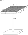
- Fig. 1 is a perspective view of concentrator photovoltaic device 1 according to the embodiment.
- concentrator photovoltaic device 1 according to the embodiment has a concentrator photovoltaic module 2.
- concentrator photovoltaic device 1 has a frame 3, a platform 4, a solar azimuth indicator (not shown), a controller (not shown), and a driver (not shown).
- Concentrator photovoltaic module 2 is disposed on frame 3. A plurality of such concentrator photovoltaic modules 2 are preferably provided. On the frame, concentrator photovoltaic modules 2 are preferably arranged in the form of a matrix. Details of the configuration of each of the concentrator photovoltaic modules will be described later.
- Frame 3 is attached on platform 4 with the driver being interposed therebetween.
- the driver includes, for example, a driving source such as a motor, and changes a direction in which frame 3 faces.
- the solar azimuth indicator is attached to frame 3, for example.
- the solar azimuth indicator detects a direction of the sun, and outputs, to the controller, a signal indicating the direction of the sun. Based on the signal from the solar azimuth indicator, the controller controls the driver such that the light receiving surface of concentrator photovoltaic module 2 faces in the direction of the sun.
- the following describes a configuration of the concentrator photovoltaic module.
- Fig. 2 is a perspective view of concentrator photovoltaic module 2 according to the embodiment.
- concentrator photovoltaic module 2 according to the embodiment has a case 21.
- Case 21 has a frame body 21a, a bottom plate 21b (see Fig. 3 ), and a top plate 21c.
- Frame body 21a constitutes side walls of concentrator photovoltaic module 2.
- Bottom plate 21b constitutes a bottom surface of the concentrator photovoltaic module.
- Top plate 21c constitutes a top surface of concentrator photovoltaic module 2.
- Fig. 3 is a top view of concentrator photovoltaic module 2 according to the embodiment.
- illustration of top plate 21c is omitted in order to clarify an internal structure of concentrator photovoltaic module 2.
- concentrator photovoltaic module 2 has a substrate 22 and concentrator photovoltaic elements 23.
- Substrate 22 is disposed on the bottom surface of case 21. That is, substrate 22 is disposed on bottom plate 21b. A plurality of such substrates 22 may be disposed. The plurality of substrates 22 are disposed side by side in a direction perpendicular to the longitudinal direction of substrate 22. Preferably, the plurality of substrates 22 are connected in parallel. Each of substrates 22 is preferably an FPC substrate.
- the plurality of concentrator photovoltaic elements 23 are provided on substrate 22, the plurality of concentrator photovoltaic elements 23 are provided. On substrate 22, concentrator photovoltaic elements 23 are arranged side by side along the longitudinal direction of substrate 22. The plurality of concentrator photovoltaic elements 23 on substrate 22 are connected in parallel.
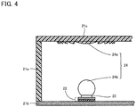
- Fig. 4 is a cross sectional view taken along IV-IV of Fig. 3 .
- concentrator photovoltaic module 2 has an optical system 24.
- Optical system 24 has a primary optical system 24a and a secondary optical system 24b.
- Primary optical system 24a is provided on top plate 21c.
- Secondary optical system 24b is provided on concentrator photovoltaic element 23.
- Primary optical system 24a collects sunlight on the secondary optical system.
- Primary optical system 24a is a Fresnel lens, for example.
- Secondary optical system 24b transmits, onto concentrator photovoltaic element 23, the sunlight collected by primary optical system 24a.
- Secondary optical system 24b is a sphere lens, for example.
- Fig. 5A is an enlarged top view of substrate 22 of concentrator photovoltaic module 2 according to the embodiment.
- Fig. 5B is an enlarged top view in a second layer of substrate 22 of concentrator photovoltaic module 2 according to the embodiment from the uppermost layer thereof.
- Fig. 5C is an enlarged top view in a third layer of substrate 22 of concentrator photovoltaic module 2 according to the embodiment from the uppermost layer thereof.
- Fig. 5D is an enlarged top view in a fourth layer of substrate 22 of concentrator photovoltaic module 2 according to the embodiment from the uppermost layer thereof.
- Fig. 5A to Fig. 5D respectively show top views of the layers of substrate 22. It should be noted that in Fig. 5A to Fig. 5D , in order to clarify structures of wiring layers 22a, illustrations of insulating layers 22b and adhesive layers 22c overlapping with and disposed above wiring layers 22a are omitted.
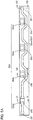
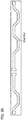
- Fig. 6 is a cross sectional view taken along VI-VI of Fig. 5A .
- Fig. 7 is a cross sectional view taken along VII-VII of Fig. 5A .
- Fig. 8 is a cross sectional view taken along VIII-VIII of Fig. 5A .
- substrate 22 has wiring layers 22a, insulating layers 22b, adhesive layers 22c, land portions 22d, through-hole conductors 22e, and an end-portion through-hole conductor 22f.
- a material with excellent thermal conductivity and excellent electric conductivity is used, such as copper (Cu).
- a material with an excellent insulating property is used, such as polyimide.
- an epoxy-resin-based adhesive agent is used, for example.
- Substrate 22 has the plurality of wiring layers 22a.
- the following describes a case where the number of wiring layers 22a is equal to the number of concentrator photovoltaic elements 23 disposed on substrate 22, i.e., a case where the number of concentrator photovoltaic elements 23 disposed on substrate 22 is 4 (these four concentrator photovoltaic elements 23 will be referred to as concentrator photovoltaic element 23a, concentrator photovoltaic element 23b, concentrator photovoltaic element 23c, and concentrator photovoltaic element 23d) and the number of wiring layers 22a is 4 (these wiring layer 22a will be referred to as wiring layer 22aa, wiring layer 22ab, wiring layer 22ac, and wiring layer 22ad).
- wiring layer 22aa is a wiring layer 22a located closest to the front surface side of substrate 22
- wiring layer 22ab is a wiring layer 22a located second closest to the front surface side of substrate 22
- wiring layer 22ac is a wiring layer 22a located third closest to the front surface side of substrate 22
- wiring layer 22ad is a wiring layer 22a located closest to the backside surface side of substrate 22.
- wiring layer 22aa, wiring layer 22ab, wiring layer 22ac, and wiring layer 22ad are stacked.
- Insulating layers 22b are provided between respective wiring layers 22a and on the front surface and backside surface of substrate 22.
- Adhesive layers 22c are provided between insulating layers 22b and wiring layers 22a.
- the plurality of land portions 22d are provided in the layer provided with wiring layer 22aa in substrate 22. That is, in the layer provided with wiring layer 22aa in substrate 22, a land portion 22da, a land portion 22db, a land portion 22dc and a land portion 22dd are provided.
- openings are provided in insulating layer 22b provided on the front surface of substrate 22, and adhesive layer 22c located just below insulating layer 22b provided on the front surface of substrate 22. From these openings, land portion 22da, land portion 22db, land portion 22dc and land portion 22dd are exposed.
- Each of concentrator photovoltaic elements 23 has a package case 23e and an element body 23f.
- a package electrode 23g is provided at a bottom surface of package case 23e.
- Package electrode 23g is electrically connected to an element electrode provided at element body 23f by way of a solder, wire bonding, or the like.
- Package electrodes 23g of concentrator photovoltaic elements 23 are connected to corresponding land portions 22d. More specifically, package electrode 23g of concentrator photovoltaic element 23a is connected to land portion 22da. Package electrode 23g of concentrator photovoltaic element 23b is connected to land portion 22db. Package electrode 23g of concentrator photovoltaic element 23c is connected to land portion 22dc. Package electrode 23g of concentrator photovoltaic element 23d is connected to land portion 22dd.
- connection between each package electrode 23g and each land portion 22d is made by a joining member 23h.
- Joining member 23h is a solder, for example.
- Land portion 22da is connected to wiring layer 22aa.
- concentrator photovoltaic element 23a is connected to wiring layer 22aa.
- land portion 22db, land portion 22dc, and land portion 22dd are not connected to wiring layer 22aa.
- the plurality of through-hole conductors 22e are provided in substrate 22. That is, in substrate 22, through-hole conductor 22eb, through-hole conductor 22ec, and through-hole conductor 22ed are provided. Each of through-hole conductors 22e is provided along a direction from the front surface of substrate 22 toward the backside surface of substrate 22.
- Through-hole conductor 22e is formed by providing a conductive layer such as a metal by way of plating on an inner circumferential surface of a through hole provided along the direction from the front surface of substrate 22 toward the backside surface of substrate 22.
- Through-hole conductor 22e may be formed by filling the inside of the through hole with a conductive layer such as a metal.
- Through-hole conductor 22eb is connected to land portion 22db. Moreover, through-hole conductor 22eb extends from the layer provided with wiring layer 22aa to the layer provided with wiring layer 22ab, and is connected to wiring layer 22ab. Accordingly, land portion 22db and wiring layer 22ab are connected to each other. As a result, concentrator photovoltaic element 23b is connected to wiring layer 22ab.
- land portion 22dc is connected to wiring layer 22ac via through-hole conductor 22ec extending from the layer provided with wiring layer 22a to the layer provided with wiring layer 22ac.
- land portion 22dd is connected to wiring layer 22ad via through-hole conductor 22ed extending from the layer provided with wiring layer 22aa to the layer provided with wiring layer 22ad.
- concentrator photovoltaic element 23c is connected to wiring layer 22ac
- concentrator photovoltaic element 23d is connected to wiring layer 22ad.
- End-portion through-hole conductor 22f is provided at the end portion of substrate 22.
- End-portion through-hole conductor 22f is provided along the direction from the front surface of substrate 22 toward the backside surface of substrate 22.
- End-portion through-hole conductor 22f is formed by providing a conductive layer such as a metal by way of plating on an inner circumferential surface of a through hole provided along the direction from the front surface of substrate 22 toward the backside surface of substrate 22.
- end-portion through-hole conductor 22f may be formed by filling the inside of the through hole with a conductive layer such as a metal. Accordingly, in end-portion through-hole conductor 22f, a cross sectional area of the wiring in a direction perpendicular to a direction in which current flows is wide.
- End-portion through-hole conductor 22f extends from the layer provided with wiring layer 22aa to the layer provided with wiring layer 22ad, and is connected to wiring layer 22aa, wiring layer 22ab, wiring layer 22ac, and wiring layer 22ad. It should be noted that end-portion through-hole conductor 22f is electrically connected to an end-portion through-hole conductor 22f of another substrate 22.
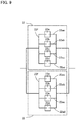
- Fig. 9 is a schematic view showing a manner of connection in concentrator photovoltaic module 2 according to the embodiment.
- concentrator photovoltaic element 23a is connected to wiring layer 22aa
- concentrator photovoltaic element 23b is connected to wiring layer 22ab
- concentrator photovoltaic element 23c is connected to wiring layer 22ac
- concentrator photovoltaic element 23d is connected to wiring layer 22ad
- wiring layer 22aa, wiring layer 22ab, wiring layer 22ac, and wiring layer 22ad are connected to one another via end-portion through-hole conductor 22f.
- the plurality of concentrator photovoltaic elements 23 are connected in parallel on substrate 22. That is, concentrator photovoltaic elements 23 connected to different wiring layers 22a are connected to each other in parallel.
- end-portion through-hole conductor 22f is connected to end-portion through-hole conductor 22f provided in another substrate 22. Accordingly, concentrator photovoltaic elements 23 on a certain substrate 22 are also connected to concentrator photovoltaic elements 23 on another substrate 22 in parallel.
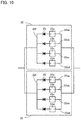
- Fig. 10 is a schematic view showing a manner of connection in concentrator photovoltaic module 2 according to a first modification of the embodiment. As shown in Fig. 10 , concentrator photovoltaic module 2 according to the first modification of the embodiment further includes a reverse current preventing unit 25.
- Reverse current preventing unit 25 permits passage of current in a direction from concentrator photovoltaic element 23 toward reverse current preventing unit 25, but blocks current in a direction from reverse current preventing unit 25 toward concentrator photovoltaic element 23.
- Reverse current preventing unit 25 is a diode, for example. In this case, the diode has an anode connected to the positive package electrode of concentrator photovoltaic element 23. Reverse current preventing unit 25 is connected to concentrator photovoltaic element 23 in series.
- Reverse current preventing unit 25 is provided for each concentrator photovoltaic element 23. That is, reverse current preventing units 25 are similarly connected to concentrator photovoltaic element 23b, concentrator photovoltaic element 23c, and concentrator photovoltaic element 23d in series, respectively.
- Fig. 11 is an enlarged top view of substrate 22 of concentrator photovoltaic module 2 according to a second modification of the embodiment.
- land portion 22da of substrate 22 of concentrator photovoltaic module 2 according to the second modification of the embodiment has a land portion 22daa and a land portion 22dab.
- land portion 22daa is connected to wiring layer 22aa.
- the other side of land portion 22daa is connected to one side of land portion 22dab.
- the other side of land portion 22dab is connected to wiring layer 22aa.
- one side of land portion 22dba is connected to wiring layer 22ab via through-hole conductor 22eb.
- the other side of land portion 22dba is connected to one side of land portion 22dbb.
- the other side of land portion 22dbb is connected to wiring layer 22ab via through-hole conductor 22eb.
- one side of land portion 22dca is connected to wiring layer 22ac via through-hole conductor 22ec.
- the other side of land portion 22dca is connected to one side of land portion 22dcb.
- the other side of land portion 22dcb is connected to wiring layer 22ac via through-hole conductor 22ec.
- land portion 22dda is connected to wiring layer 22ad via through-hole conductor 22ed.
- the other side of land portion 22dda is connected to one side of land portion 22ddb.
- the other side of land portion 22ddb is connected to wiring layer 22ad via through-hole conductor 22ed.
- Package electrode 23g of concentrator photovoltaic element 23aa is connected to land portion 22daa.
- Package electrode 23g of concentrator photovoltaic element 23ab is connected to land portion 22dab. That is, concentrator photovoltaic element 23aa and concentrator photovoltaic element 23ab connected to the same wiring layer 22a are connected to each other in series.
- concentrator photovoltaic element 23ba and concentrator photovoltaic element 23bb connected to wiring layer 22ab are connected to each other in series
- concentrator photovoltaic element 23ca and concentrator photovoltaic element 23cb connected to wiring layer 22ac are connected to each other in series
- concentrator photovoltaic element 23da and concentrator photovoltaic element 23db connected to wiring layer 22ad are connected to each other in series.
- concentrator photovoltaic elements 23 connected to different wiring layers 22a are connected to each other in parallel, and concentrator photovoltaic elements 23 connected to the same wiring layer 22a are connected to each other in series.
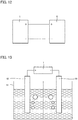
- Fig. 12 is a schematic view of a hydrogen generating system according to the embodiment.
- the hydrogen generating system according to the embodiment has concentrator photovoltaic device 1 according to the embodiment, and a hydrogen generating device 5.
- the output of concentrator photovoltaic device 1 is connected to hydrogen generating device 5. Accordingly, electric power generated in concentrator photovoltaic device 1 is supplied to hydrogen generating device 5.
- Fig. 13 is a schematic view of hydrogen generating device 5 in the hydrogen generating system according to the embodiment.
- hydrogen generating device 5 has a reservoir 51, a positive electrode 52, and a negative electrode 53. Water to be electrolyzed is stored in reservoir 51. Positive electrode 52 and negative electrode 53 are immersed in the water stored in reservoir 51. Positive electrode 52 and negative electrode 53 are connected to the output of concentrator photovoltaic device 1.
- Electric power is supplied from concentrator photovoltaic device 1 to hydrogen generating device 5, whereby the water is electrolyzed in positive electrode 52 and negative electrode 53. As a result, hydrogen is generated from the negative electrode, and oxygen is generated from the positive electrode.
- Fig. 14 is a schematic view showing a manner of connection between hydrogen generating devices 5 and concentrator photovoltaic device 1 in the hydrogen generating system according to the embodiment. As shown in Fig. 14 , the plurality of hydrogen generating devices 5 may be connected to concentrator photovoltaic device 1 in series.
- concentrator photovoltaic device 1 and hydrogen generating devices 5 are connected to each other such that voltage decreased by hydrogen generating devices 5 connected in series becomes more than or equal to 80% with respect to the output voltage of concentrator photovoltaic device 1.
- voltage decreased by a hydrogen generating device 5 is of about 1.7 V. Therefore, voltage decreased when five hydrogen generating devices 5 are connected in series is of about 8.5 V.
- the output voltage of one concentrator photovoltaic element 23 is of about 3.0 V.
- the output voltage of concentrator photovoltaic device 1 becomes about 9.0 V when nine concentrator photovoltaic elements 23 are provided on substrate 22, three wiring layers 22a are provided, and three concentrator photovoltaic elements 23 are connected in series for each wiring layer 22a. Therefore, the above-described ratio is attained in this example.
- a wiring space is limited. Accordingly, a degree of freedom in wiring design is limited extremely. Furthermore, a wiring width has to be narrow in this case. Such a narrow wiring width leads to increased wiring resistance to result in a problem of heat generation.
- substrate 22 has the plurality of wiring layers 22a.
- the output voltage can be decreased while suppressing increase of wiring resistance without limiting the degree of freedom in wiring design.
- concentrator photovoltaic module 2 since the plurality of concentrator photovoltaic elements 23 are connected in parallel, it is necessary to consider a problem of reverse current.
- concentrator photovoltaic module 2 according to the embodiment has reverse current preventing units 25 connected to concentrator photovoltaic elements 23 in series, the output voltage can be decreased while preventing occurrence of reverse current.
- the output voltage can be accordingly adjusted. That is, the output voltage can be optimized in accordance with a requirement specification of the device (for example, hydrogen generating device 5) connected to concentrator photovoltaic device 1.
- concentrator photovoltaic module 2 In concentrator photovoltaic module 2 according to the embodiment, a large amount of current flows at a portion at which the plurality of wiring layers 22a are connected to each other.
- concentrator photovoltaic module 2 according to the embodiment has end-portion through-hole conductor 22f, a cross-sectional area of the wiring is increased at the portion at which the plurality of wiring layers 22a are connected to each other, thereby suppressing the problem of generation of heat caused by flow of a large amount of current.
- the output voltage can be decreased even when the number of concentrator photovoltaic elements 23 mounted thereon is increased.
- concentrator photovoltaic device 1 according to the embodiment has the concentrator photovoltaic module according to the embodiment, the above-described effect is also exhibited.
- the output voltage of concentrator photovoltaic device 1 is high unlike the hydrogen generating system according to the embodiment, the voltage decreased by hydrogen generating devices 5 becomes lower than the output voltage of concentrator photovoltaic device 1. Accordingly, in order to avoid electric power loss, it is necessary to connect an extremely large number of hydrogen generating devices 5 in series.
- the hydrogen generating system according to the embodiment since the output voltage of concentrator photovoltaic device 1 is low, it is not necessary to connect a large number of hydrogen generating devices 5 in series. That is, in the hydrogen generating system according to the embodiment, the electric power loss can be readily addressed by increasing surface areas of positive electrode 52 and negative electrode 53 of hydrogen generating device 5 in accordance with the output current increased due to the decrease of the output voltage of concentrator photovoltaic device 1.
- 1 concentrator photovoltaic device; 2: concentrator photovoltaic module; 21: case; 21a: frame body; 21b: bottom plate; 21c: top plate; 22: substrate; 22a, 22aa, 22ab, 22ad: wiring layer; 22b: insulating layer; 22c: adhesive layer; 22d, 22da, 22daa, 22dab, 22db, 22dba, 22dbb, 22dc, 22dca, 22dcb, 22dd, 22dda, 22ddb: land portion; 22e, 22eb, 22ec, 22ed: through-hole conductor; 22f: end-portion through-hole conductor; 23, 23a, 23aa, 23ab, 23b, 23ba, 23bb, 23c, 23ca, 23cb, 23d, 23da, 23db: concentrator photovoltaic element; 23e: package case; 23f: element body; 23g: package electrode; 23h: joining member; 24: optical system; 24a
Landscapes
- Photovoltaic Devices (AREA)
- Life Sciences & Earth Sciences (AREA)
- Sustainable Development (AREA)
Abstract
Description
- The present disclosure relates to a concentrator photovoltaic module, a concentrator photovoltaic device, and a hydrogen generating system. The present application claims a priority based on Japanese Patent Application No.
2016-134836 filed on July 7, 2016 - A concentrator photovoltaic module described in
WO 2016/006573 (Patent Literature 1) includes: a case; FPC (Flexible Printed Circuit) substrates disposed on a bottom surface of the case; and a plurality of concentrator photovoltaic elements disposed on each FPC substrate. In the concentrator photovoltaic module described inPatent Literature 1, the FPC substrates are connected in series, and the plurality of concentrator photovoltaic elements on each FPC substrate are connected in series. - For example, Japanese Patent Laying-Open No.
2012-94684 Patent Literature 2, the hydrogen generating device is configured to electrolyze water using electric power supplied from the concentrator photovoltaic device, thereby generating hydrogen. -
- PTL 1:
WO 2016/006573 - PTL 2: Japanese Patent Laying-Open No.
2012-94684 - A concentrator photovoltaic module according to one embodiment of the present disclosure includes: a case; a substrate disposed on a bottom surface of the case and having a plurality of stacked wiring layers; and concentrator photovoltaic elements disposed on the substrate and connected to the wiring layers. The concentrator photovoltaic elements connected to different wiring layers are connected to each other in parallel.
-
-
Fig. 1 is a perspective view of a concentratorphotovoltaic device 1 according to an embodiment. -
Fig. 2 is a perspective view of a concentratorphotovoltaic module 2 according to the embodiment. -
Fig. 3 is a top view of concentratorphotovoltaic module 2 according to the embodiment. -
Fig. 4 is a cross sectional view taken along IV-IV inFig. 3 . -
Fig. 5A is an enlarged top view of asubstrate 22 of concentratorphotovoltaic module 2 according to the embodiment. -
Fig. 5B is an enlarged top view in a second layer ofsubstrate 22 of concentratorphotovoltaic module 2 according to the embodiment from the uppermost layer thereof. -
Fig. 5C is an enlarged top view in a third layer ofsubstrate 22 of concentratorphotovoltaic module 2 according to the embodiment from the uppermost layer thereof. -
Fig. 5D is an enlarged top view in a fourth layer ofsubstrate 22 of concentratorphotovoltaic module 2 according to the embodiment from the uppermost layer thereof. -
Fig. 6 is a cross sectional view taken along VI-VI ofFig. 5A . -
Fig. 7 is a cross sectional view taken along VII-VII ofFig. 5A . -
Fig. 8 is a cross sectional view taken along VIII-VIII ofFig. 5A . -
Fig. 9 is a schematic view showing a manner of connection in concentratorphotovoltaic module 2 according to the embodiment. -
Fig. 10 is a schematic view showing a manner of connection in concentratorphotovoltaic module 2 according to a first modification of the embodiment. -
Fig. 11 is an enlarged top view of asubstrate 22 of a concentratorphotovoltaic module 2 according to a second modification of the embodiment. -
Fig. 12 is a schematic view of a hydrogen generating system according to the embodiment. -
Fig. 13 is a schematic view of ahydrogen generating device 5 in the hydrogen generating system according to the embodiment. -
Fig. 14 is a schematic view showing a manner of connection betweenhydrogen generating devices 5 and concentratorphotovoltaic device 1 in the hydrogen generating system according to the embodiment. - In the concentrator photovoltaic module described in
Patent Literature 1, the plurality of concentrator photovoltaic elements are connected in series as described above. Hence, voltage output from the concentrator photovoltaic module is generally more than or equal to 50 V. In order to electrolyze water in the hydrogen generating device to generate hydrogen, supply of voltage of about 1.7 V is sufficient. If voltage higher than this is supplied, there will be a loss. Thus, the voltage output from the concentrator photovoltaic device may be preferably low. - According to the description above, output voltage from a concentrator photovoltaic module can be decreased.
- First, embodiments of the present disclosure are listed and described.
- Hereinafter, details of the embodiments of the present disclosure will be described with reference to the figures. It should be noted that the same or corresponding portions in the figures are given the same reference characters. Moreover, at least a part of the embodiments described below may be appropriately combined.
- (1) A concentrator photovoltaic module according to one embodiment includes: a case; a substrate disposed on a bottom surface of the case and having a plurality of stacked wiring layers; and concentrator photovoltaic elements disposed on the substrate and connected to the wiring layers. The concentrator photovoltaic elements connected to different wiring layers are connected to each other in parallel.
According to the concentrator photovoltaic module according to (1), output voltage can be decreased while suppressing increase of wiring resistance without limiting the degree of freedom in wiring design. - (2) The concentrator photovoltaic module according to (1) may further include a reverse current preventing unit connected to each of the concentrator photovoltaic elements in series, wherein the reverse current preventing unit may be configured to permit passage of current in a direction from the concentrator photovoltaic element toward the reverse current preventing unit, and may be configured to block current in a direction from the reverse current preventing unit toward the concentrator photovoltaic element.
According to the concentrator photovoltaic module according to (2), the output voltage can be decreased while preventing occurrence of reverse current. - (3) In the concentrator photovoltaic module according to (1) or (2), the concentrator photovoltaic elements connected to the same wiring layer may be connected to each other in series.
According to the concentrator photovoltaic module according to (3), the output voltage can be adjusted, whereby the output voltage can be optimized in accordance with a requirement specification of a device connected to the concentrator photovoltaic device. - (4) In the concentrator photovoltaic module according to any one of (1) to (3), the substrate may have an end-portion through-hole conductor disposed at an end portion of the substrate and connected to the plurality of wiring layers.
According to the concentrator photovoltaic module according to (4), a cross-sectional area of the wiring is increased at a portion at which the plurality of wiring layers are connected to each other, thereby suppressing a problem of generation of heat caused by flow of a large amount of current. - (5) In the concentrator photovoltaic module according to any one of (1) to (4), a plurality of the substrates may be provided, and the plurality of the substrates may be connected to each other in parallel.
According to the concentrator photovoltaic module according to (5), the output voltage can be decreased even when a larger number of concentrator photovoltaic elements are mounted. - (6) A concentrator photovoltaic device according to one embodiment includes the concentrator photovoltaic module recited in any one of (1) to (5). According to the concentrator photovoltaic device according to (6), the same effects as those in (1) to (5) are exhibited.
- (7) A hydrogen generating system according to one embodiment may include: the concentrator photovoltaic device recited in (6); and a plurality of hydrogen generating devices connected to the concentrator photovoltaic device in series, wherein a ratio of voltage decreased by the plurality of hydrogen generating devices to output voltage of the concentrator photovoltaic device may be more than or equal to 80%.
- According to the hydrogen generating system according to (7), electric power generated in the concentrator photovoltaic device can be suppressed from being lost.
- Hereinafter, details of the embodiments of the present disclosure will be described with reference to figures. It should be noted that the same or corresponding portions in the figures are given the same reference characters. Moreover, at least a part of the embodiments described below may be appropriately combined.
- The following describes a configuration of a concentrator
photovoltaic device 1 according to the embodiment. -
Fig. 1 is a perspective view of concentratorphotovoltaic device 1 according to the embodiment. As shown inFig. 1 , concentratorphotovoltaic device 1 according to the embodiment has a concentratorphotovoltaic module 2. Moreover, concentratorphotovoltaic device 1 has aframe 3, aplatform 4, a solar azimuth indicator (not shown), a controller (not shown), and a driver (not shown). - Concentrator
photovoltaic module 2 is disposed onframe 3. A plurality of such concentratorphotovoltaic modules 2 are preferably provided. On the frame, concentratorphotovoltaic modules 2 are preferably arranged in the form of a matrix. Details of the configuration of each of the concentrator photovoltaic modules will be described later. -
Frame 3 is attached onplatform 4 with the driver being interposed therebetween. The driver includes, for example, a driving source such as a motor, and changes a direction in whichframe 3 faces. The solar azimuth indicator is attached toframe 3, for example. The solar azimuth indicator detects a direction of the sun, and outputs, to the controller, a signal indicating the direction of the sun. Based on the signal from the solar azimuth indicator, the controller controls the driver such that the light receiving surface of concentratorphotovoltaic module 2 faces in the direction of the sun. - The following describes a configuration of the concentrator photovoltaic module.
-
Fig. 2 is a perspective view of concentratorphotovoltaic module 2 according to the embodiment. As shown inFig. 2 , concentratorphotovoltaic module 2 according to the embodiment has acase 21.Case 21 has aframe body 21a, abottom plate 21b (seeFig. 3 ), and atop plate 21c.Frame body 21a constitutes side walls of concentratorphotovoltaic module 2.Bottom plate 21b constitutes a bottom surface of the concentrator photovoltaic module.Top plate 21c constitutes a top surface of concentratorphotovoltaic module 2. -
Fig. 3 is a top view of concentratorphotovoltaic module 2 according to the embodiment. InFig. 3 , illustration oftop plate 21c is omitted in order to clarify an internal structure of concentratorphotovoltaic module 2. As shown inFig. 3 , concentratorphotovoltaic module 2 has asubstrate 22 and concentratorphotovoltaic elements 23. -
Substrate 22 is disposed on the bottom surface ofcase 21. That is,substrate 22 is disposed onbottom plate 21b. A plurality ofsuch substrates 22 may be disposed. The plurality ofsubstrates 22 are disposed side by side in a direction perpendicular to the longitudinal direction ofsubstrate 22. Preferably, the plurality ofsubstrates 22 are connected in parallel. Each ofsubstrates 22 is preferably an FPC substrate. - On
substrate 22, the plurality of concentratorphotovoltaic elements 23 are provided. Onsubstrate 22, concentratorphotovoltaic elements 23 are arranged side by side along the longitudinal direction ofsubstrate 22. The plurality of concentratorphotovoltaic elements 23 onsubstrate 22 are connected in parallel. -
Fig. 4 is a cross sectional view taken along IV-IV ofFig. 3 . As shown inFig. 4 , concentratorphotovoltaic module 2 has anoptical system 24.Optical system 24 has a primaryoptical system 24a and a secondaryoptical system 24b. Primaryoptical system 24a is provided ontop plate 21c. Secondaryoptical system 24b is provided on concentratorphotovoltaic element 23. - Primary
optical system 24a collects sunlight on the secondary optical system. Primaryoptical system 24a is a Fresnel lens, for example. Secondaryoptical system 24b transmits, onto concentratorphotovoltaic element 23, the sunlight collected by primaryoptical system 24a. Secondaryoptical system 24b is a sphere lens, for example. -
Fig. 5A is an enlarged top view ofsubstrate 22 of concentratorphotovoltaic module 2 according to the embodiment.Fig. 5B is an enlarged top view in a second layer ofsubstrate 22 of concentratorphotovoltaic module 2 according to the embodiment from the uppermost layer thereof.Fig. 5C is an enlarged top view in a third layer ofsubstrate 22 of concentratorphotovoltaic module 2 according to the embodiment from the uppermost layer thereof.Fig. 5D is an enlarged top view in a fourth layer ofsubstrate 22 of concentratorphotovoltaic module 2 according to the embodiment from the uppermost layer thereof.Fig. 5A to Fig. 5D respectively show top views of the layers ofsubstrate 22. It should be noted that inFig. 5A to Fig. 5D , in order to clarify structures ofwiring layers 22a, illustrations of insulatinglayers 22b andadhesive layers 22c overlapping with and disposed abovewiring layers 22a are omitted. -
Fig. 6 is a cross sectional view taken along VI-VI ofFig. 5A .Fig. 7 is a cross sectional view taken along VII-VII ofFig. 5A .Fig. 8 is a cross sectional view taken along VIII-VIII ofFig. 5A . - As shown in
Fig. 5A to Fig. 5D ,Fig. 6, Fig. 7, and Fig. 8 ,substrate 22 haswiring layers 22a, insulatinglayers 22b,adhesive layers 22c,land portions 22d, through-hole conductors 22e, and an end-portion through-hole conductor 22f. - For each of
wiring layers 22a, a material with excellent thermal conductivity and excellent electric conductivity is used, such as copper (Cu). For each of insulatinglayers 22b, a material with an excellent insulating property is used, such as polyimide. For each ofadhesive layers 22c, an epoxy-resin-based adhesive agent is used, for example. -
Substrate 22 has the plurality ofwiring layers 22a. As a specific example, the following describes a case where the number ofwiring layers 22a is equal to the number of concentratorphotovoltaic elements 23 disposed onsubstrate 22, i.e., a case where the number of concentratorphotovoltaic elements 23 disposed onsubstrate 22 is 4 (these four concentratorphotovoltaic elements 23 will be referred to as concentratorphotovoltaic element 23a, concentratorphotovoltaic element 23b, concentratorphotovoltaic element 23c, and concentratorphotovoltaic element 23d) and the number ofwiring layers 22a is 4 (thesewiring layer 22a will be referred to as wiring layer 22aa, wiring layer 22ab, wiring layer 22ac, and wiring layer 22ad). - It should be noted that: wiring layer 22aa is a
wiring layer 22a located closest to the front surface side ofsubstrate 22; wiring layer 22ab is awiring layer 22a located second closest to the front surface side ofsubstrate 22; wiring layer 22ac is awiring layer 22a located third closest to the front surface side ofsubstrate 22; and wiring layer 22ad is awiring layer 22a located closest to the backside surface side ofsubstrate 22. - In
substrate 22, wiring layer 22aa, wiring layer 22ab, wiring layer 22ac, and wiring layer 22ad are stacked. Insulatinglayers 22b are provided betweenrespective wiring layers 22a and on the front surface and backside surface ofsubstrate 22.Adhesive layers 22c are provided between insulatinglayers 22b andwiring layers 22a. - The plurality of
land portions 22d are provided in the layer provided with wiring layer 22aa insubstrate 22. That is, in the layer provided with wiring layer 22aa insubstrate 22, a land portion 22da, a land portion 22db, a land portion 22dc and a land portion 22dd are provided. - It should be noted that openings are provided in insulating
layer 22b provided on the front surface ofsubstrate 22, andadhesive layer 22c located just below insulatinglayer 22b provided on the front surface ofsubstrate 22. From these openings, land portion 22da, land portion 22db, land portion 22dc and land portion 22dd are exposed. - Each of concentrator
photovoltaic elements 23 has apackage case 23e and anelement body 23f. Apackage electrode 23g is provided at a bottom surface ofpackage case 23e.Package electrode 23g is electrically connected to an element electrode provided atelement body 23f by way of a solder, wire bonding, or the like. -
Package electrodes 23g of concentratorphotovoltaic elements 23 are connected to correspondingland portions 22d. More specifically,package electrode 23g of concentratorphotovoltaic element 23a is connected to land portion 22da.Package electrode 23g of concentratorphotovoltaic element 23b is connected to land portion 22db.Package electrode 23g of concentratorphotovoltaic element 23c is connected to land portion 22dc.Package electrode 23g of concentratorphotovoltaic element 23d is connected to land portion 22dd. - The connection between each
package electrode 23g and eachland portion 22d is made by a joiningmember 23h. Joiningmember 23h is a solder, for example. - Land portion 22da is connected to wiring layer 22aa. As a result, concentrator
photovoltaic element 23a is connected to wiring layer 22aa. On the other hand, land portion 22db, land portion 22dc, and land portion 22dd are not connected to wiring layer 22aa. - The plurality of through-hole conductors 22e are provided in
substrate 22. That is, insubstrate 22, through-hole conductor 22eb, through-hole conductor 22ec, and through-hole conductor 22ed are provided. Each of through-hole conductors 22e is provided along a direction from the front surface ofsubstrate 22 toward the backside surface ofsubstrate 22. Through-hole conductor 22e is formed by providing a conductive layer such as a metal by way of plating on an inner circumferential surface of a through hole provided along the direction from the front surface ofsubstrate 22 toward the backside surface ofsubstrate 22. Through-hole conductor 22e may be formed by filling the inside of the through hole with a conductive layer such as a metal. - Through-hole conductor 22eb is connected to land portion 22db. Moreover, through-hole conductor 22eb extends from the layer provided with wiring layer 22aa to the layer provided with wiring layer 22ab, and is connected to wiring layer 22ab. Accordingly, land portion 22db and wiring layer 22ab are connected to each other. As a result, concentrator
photovoltaic element 23b is connected to wiring layer 22ab. - Although not shown in the figures, in the same manner, land portion 22dc is connected to wiring layer 22ac via through-hole conductor 22ec extending from the layer provided with
wiring layer 22a to the layer provided with wiring layer 22ac. In the same manner, land portion 22dd is connected to wiring layer 22ad via through-hole conductor 22ed extending from the layer provided with wiring layer 22aa to the layer provided with wiring layer 22ad. - As a result, concentrator
photovoltaic element 23c is connected to wiring layer 22ac, and concentratorphotovoltaic element 23d is connected to wiring layer 22ad. - End-portion through-
hole conductor 22f is provided at the end portion ofsubstrate 22. End-portion through-hole conductor 22f is provided along the direction from the front surface ofsubstrate 22 toward the backside surface ofsubstrate 22. End-portion through-hole conductor 22f is formed by providing a conductive layer such as a metal by way of plating on an inner circumferential surface of a through hole provided along the direction from the front surface ofsubstrate 22 toward the backside surface ofsubstrate 22. It should be noted that end-portion through-hole conductor 22f may be formed by filling the inside of the through hole with a conductive layer such as a metal. Accordingly, in end-portion through-hole conductor 22f, a cross sectional area of the wiring in a direction perpendicular to a direction in which current flows is wide. - End-portion through-
hole conductor 22f extends from the layer provided with wiring layer 22aa to the layer provided with wiring layer 22ad, and is connected to wiring layer 22aa, wiring layer 22ab, wiring layer 22ac, and wiring layer 22ad. It should be noted that end-portion through-hole conductor 22f is electrically connected to an end-portion through-hole conductor 22f of anothersubstrate 22. -
Fig. 9 is a schematic view showing a manner of connection in concentratorphotovoltaic module 2 according to the embodiment. As described above, concentratorphotovoltaic element 23a is connected to wiring layer 22aa, concentratorphotovoltaic element 23b is connected to wiring layer 22ab, concentratorphotovoltaic element 23c is connected to wiring layer 22ac, concentratorphotovoltaic element 23d is connected to wiring layer 22ad, and wiring layer 22aa, wiring layer 22ab, wiring layer 22ac, and wiring layer 22ad are connected to one another via end-portion through-hole conductor 22f. - Accordingly, as shown in
Fig. 9 , the plurality of concentratorphotovoltaic elements 23 are connected in parallel onsubstrate 22. That is, concentratorphotovoltaic elements 23 connected todifferent wiring layers 22a are connected to each other in parallel. - Moreover, as described above, end-portion through-
hole conductor 22f is connected to end-portion through-hole conductor 22f provided in anothersubstrate 22. Accordingly, concentratorphotovoltaic elements 23 on acertain substrate 22 are also connected to concentratorphotovoltaic elements 23 on anothersubstrate 22 in parallel. -
Fig. 10 is a schematic view showing a manner of connection in concentratorphotovoltaic module 2 according to a first modification of the embodiment. As shown inFig. 10 , concentratorphotovoltaic module 2 according to the first modification of the embodiment further includes a reverse current preventingunit 25. - Reverse current preventing
unit 25 permits passage of current in a direction from concentratorphotovoltaic element 23 toward reverse current preventingunit 25, but blocks current in a direction from reverse current preventingunit 25 toward concentratorphotovoltaic element 23. Reverse current preventingunit 25 is a diode, for example. In this case, the diode has an anode connected to the positive package electrode of concentratorphotovoltaic element 23. Reverse current preventingunit 25 is connected to concentratorphotovoltaic element 23 in series. - Reverse current preventing
unit 25 is provided for each concentratorphotovoltaic element 23. That is, reverse current preventingunits 25 are similarly connected to concentratorphotovoltaic element 23b, concentratorphotovoltaic element 23c, and concentratorphotovoltaic element 23d in series, respectively. -
Fig. 11 is an enlarged top view ofsubstrate 22 of concentratorphotovoltaic module 2 according to a second modification of the embodiment. As shown inFig. 11 , land portion 22da ofsubstrate 22 of concentratorphotovoltaic module 2 according to the second modification of the embodiment has a land portion 22daa and a land portion 22dab. - One side of land portion 22daa is connected to wiring layer 22aa. The other side of land portion 22daa is connected to one side of land portion 22dab. The other side of land portion 22dab is connected to wiring layer 22aa.
- Although not shown, one side of land portion 22dba is connected to wiring layer 22ab via through-hole conductor 22eb. The other side of land portion 22dba is connected to one side of land portion 22dbb. The other side of land portion 22dbb is connected to wiring layer 22ab via through-hole conductor 22eb.
- Similarly, one side of land portion 22dca is connected to wiring layer 22ac via through-hole conductor 22ec. The other side of land portion 22dca is connected to one side of land portion 22dcb. The other side of land portion 22dcb is connected to wiring layer 22ac via through-hole conductor 22ec.
- Similarly, one side of land portion 22dda is connected to wiring layer 22ad via through-hole conductor 22ed. The other side of land portion 22dda is connected to one side of land portion 22ddb. The other side of land portion 22ddb is connected to wiring layer 22ad via through-hole conductor 22ed.
-
Package electrode 23g of concentrator photovoltaic element 23aa is connected to land portion 22daa.Package electrode 23g of concentrator photovoltaic element 23ab is connected to land portion 22dab. That is, concentrator photovoltaic element 23aa and concentrator photovoltaic element 23ab connected to thesame wiring layer 22a are connected to each other in series. - The same applies to
other wiring layers 22a. That is, concentrator photovoltaic element 23ba and concentrator photovoltaic element 23bb connected to wiring layer 22ab are connected to each other in series, concentrator photovoltaic element 23ca and concentrator photovoltaic element 23cb connected to wiring layer 22ac are connected to each other in series, and concentrator photovoltaic element 23da and concentrator photovoltaic element 23db connected to wiring layer 22ad are connected to each other in series. - As described above, in the second modification of the embodiment, concentrator
photovoltaic elements 23 connected todifferent wiring layers 22a are connected to each other in parallel, and concentratorphotovoltaic elements 23 connected to thesame wiring layer 22a are connected to each other in series. -
Fig. 12 is a schematic view of a hydrogen generating system according to the embodiment. As shown inFig. 12 , the hydrogen generating system according to the embodiment has concentratorphotovoltaic device 1 according to the embodiment, and ahydrogen generating device 5. The output of concentratorphotovoltaic device 1 is connected tohydrogen generating device 5. Accordingly, electric power generated in concentratorphotovoltaic device 1 is supplied tohydrogen generating device 5. -
Fig. 13 is a schematic view ofhydrogen generating device 5 in the hydrogen generating system according to the embodiment. As shown inFig. 13 ,hydrogen generating device 5 has areservoir 51, apositive electrode 52, and anegative electrode 53. Water to be electrolyzed is stored inreservoir 51.Positive electrode 52 andnegative electrode 53 are immersed in the water stored inreservoir 51.Positive electrode 52 andnegative electrode 53 are connected to the output of concentratorphotovoltaic device 1. - Electric power is supplied from concentrator
photovoltaic device 1 tohydrogen generating device 5, whereby the water is electrolyzed inpositive electrode 52 andnegative electrode 53. As a result, hydrogen is generated from the negative electrode, and oxygen is generated from the positive electrode. -
Fig. 14 is a schematic view showing a manner of connection betweenhydrogen generating devices 5 and concentratorphotovoltaic device 1 in the hydrogen generating system according to the embodiment. As shown inFig. 14 , the plurality ofhydrogen generating devices 5 may be connected to concentratorphotovoltaic device 1 in series. - Preferably, concentrator
photovoltaic device 1 andhydrogen generating devices 5 are connected to each other such that voltage decreased byhydrogen generating devices 5 connected in series becomes more than or equal to 80% with respect to the output voltage of concentratorphotovoltaic device 1. - For example, voltage decreased by a
hydrogen generating device 5 is of about 1.7 V. Therefore, voltage decreased when fivehydrogen generating devices 5 are connected in series is of about 8.5 V. On the other hand, the output voltage of one concentratorphotovoltaic element 23 is of about 3.0 V. - Therefore, the output voltage of concentrator
photovoltaic device 1 becomes about 9.0 V when nine concentratorphotovoltaic elements 23 are provided onsubstrate 22, threewiring layers 22a are provided, and three concentratorphotovoltaic elements 23 are connected in series for eachwiring layer 22a. Therefore, the above-described ratio is attained in this example. - The following describes an effect of concentrator
photovoltaic module 2 according to the embodiment. - When the plurality of concentrator
photovoltaic elements 23 are connected in parallel without usingmultiple wiring layers 22a unlike concentratorphotovoltaic module 2 according to the embodiment, a wiring space is limited. Accordingly, a degree of freedom in wiring design is limited extremely. Furthermore, a wiring width has to be narrow in this case. Such a narrow wiring width leads to increased wiring resistance to result in a problem of heat generation. - On the other hand, in the concentrator photovoltaic module according to the embodiment,
substrate 22 has the plurality ofwiring layers 22a. Hence, according to concentratorphotovoltaic module 2 according to the embodiment, the output voltage can be decreased while suppressing increase of wiring resistance without limiting the degree of freedom in wiring design. - In concentrator
photovoltaic module 2 according to the embodiment, since the plurality of concentratorphotovoltaic elements 23 are connected in parallel, it is necessary to consider a problem of reverse current. When concentratorphotovoltaic module 2 according to the embodiment has reverse current preventingunits 25 connected to concentratorphotovoltaic elements 23 in series, the output voltage can be decreased while preventing occurrence of reverse current. - In concentrator
photovoltaic module 2 according to the embodiment, when concentratorphotovoltaic elements 23 connected to thesame wiring layer 22a are connected to each other in series, the output voltage can be accordingly adjusted. That is, the output voltage can be optimized in accordance with a requirement specification of the device (for example, hydrogen generating device 5) connected to concentratorphotovoltaic device 1. - In concentrator
photovoltaic module 2 according to the embodiment, a large amount of current flows at a portion at which the plurality ofwiring layers 22a are connected to each other. When concentratorphotovoltaic module 2 according to the embodiment has end-portion through-hole conductor 22f, a cross-sectional area of the wiring is increased at the portion at which the plurality ofwiring layers 22a are connected to each other, thereby suppressing the problem of generation of heat caused by flow of a large amount of current. - In concentrator
photovoltaic module 2 according to the embodiment, in the case where the plurality ofsubstrates 22 are provided and are connected to each other in parallel, the output voltage can be decreased even when the number of concentratorphotovoltaic elements 23 mounted thereon is increased. - The following describes an effect of concentrator
photovoltaic device 1 according to the embodiment. - Since concentrator
photovoltaic device 1 according to the embodiment has the concentrator photovoltaic module according to the embodiment, the above-described effect is also exhibited. - The following describes an effect of the hydrogen generating system according to the embodiment.
- If the output voltage of concentrator
photovoltaic device 1 is high unlike the hydrogen generating system according to the embodiment, the voltage decreased byhydrogen generating devices 5 becomes lower than the output voltage of concentratorphotovoltaic device 1. Accordingly, in order to avoid electric power loss, it is necessary to connect an extremely large number ofhydrogen generating devices 5 in series. - On the other hand, in the hydrogen generating system according to the embodiment, since the output voltage of concentrator
photovoltaic device 1 is low, it is not necessary to connect a large number ofhydrogen generating devices 5 in series. That is, in the hydrogen generating system according to the embodiment, the electric power loss can be readily addressed by increasing surface areas ofpositive electrode 52 andnegative electrode 53 ofhydrogen generating device 5 in accordance with the output current increased due to the decrease of the output voltage of concentratorphotovoltaic device 1. - In the hydrogen generation system according to the embodiment, when the voltage decreased by
hydrogen generating devices 5 connected in series is more than or equal to 80% with respect to the output voltage of concentratorphotovoltaic device 1, electric power generated in concentratorphotovoltaic device 1 can be suppressed from being lost. - The embodiments disclosed herein are illustrative and non-restrictive in any respect. The scope of the present invention is defined by the terms of the claims, rather than the embodiments described above, and is intended to include any modifications within the scope and meaning equivalent to the terms of the claims.
- 1: concentrator photovoltaic device; 2: concentrator photovoltaic module; 21: case; 21a: frame body; 21b: bottom plate; 21c: top plate; 22: substrate; 22a, 22aa, 22ab, 22ad: wiring layer; 22b: insulating layer; 22c: adhesive layer; 22d, 22da, 22daa, 22dab, 22db, 22dba, 22dbb, 22dc, 22dca, 22dcb, 22dd, 22dda, 22ddb: land portion; 22e, 22eb, 22ec, 22ed: through-hole conductor; 22f: end-portion through-hole conductor; 23, 23a, 23aa, 23ab, 23b, 23ba, 23bb, 23c, 23ca, 23cb, 23d, 23da, 23db: concentrator photovoltaic element; 23e: package case; 23f: element body; 23g: package electrode; 23h: joining member; 24: optical system; 24a: primary optical system; 24b: secondary optical system; 25: reverse current preventing unit; 3: frame; 4: platform; 5: hydrogen generating device; 51: reservoir; 52: positive electrode; 53: negative electrode.
Claims (7)
- A concentrator photovoltaic module comprising:a case;a substrate disposed on a bottom surface of the case and having a plurality of stacked wiring layers; anda plurality of concentrator photovoltaic elements disposed on the substrate and connected to the wiring layers, whereinthe concentrator photovoltaic elements connected to different wiring layers are connected to each other in parallel.
- The concentrator photovoltaic module according to claim 1, further comprising a reverse current preventing unit connected to each of the concentrator photovoltaic elements in series, wherein
the reverse current preventing unit is configured to permit passage of current in a direction from the concentrator photovoltaic element toward the reverse current preventing unit, and is configured to block current in a direction from the reverse current preventing unit toward the concentrator photovoltaic element. - The concentrator photovoltaic module according to claim 1 or 2, wherein the concentrator photovoltaic elements connected to the same wiring layer are connected to each other in series.
- The concentrator photovoltaic module according to any one of claims 1 to 3, wherein the substrate has an end-portion through-hole conductor disposed at an end portion of the substrate and connected to the plurality of wiring layers.
- The concentrator photovoltaic module according to any one of claims 1 to 4, wherein
a plurality of the substrates are provided, and
the plurality of the substrates are connected to each other in parallel. - A concentrator photovoltaic device comprising the concentrator photovoltaic module recited in any one of claims 1 to 5.
- A hydrogen generating system comprising:the concentrator photovoltaic device recited in claim 6; anda plurality of hydrogen generating devices configured to generate hydrogen using electric power supplied from the concentrator photovoltaic device, whereinthe plurality of hydrogen generating devices are connected to each other in series, anda ratio of voltage decreased by the plurality of hydrogen generating devices to output voltage of the concentrator photovoltaic device is more than or equal to 80%.
Applications Claiming Priority (2)
| Application Number | Priority Date | Filing Date | Title |
|---|---|---|---|
| JP2016134836A JP6759778B2 (en) | 2016-07-07 | 2016-07-07 | Condensing photovoltaic module, photovoltaic power generation equipment and hydrogen purification system |
| PCT/JP2017/021063 WO2018008322A1 (en) | 2016-07-07 | 2017-06-07 | Concentrator photovoltaic power generation module, concentrator photovoltaic power generation device, and hydrogen purification system |
Publications (2)
| Publication Number | Publication Date |
|---|---|
| EP3483942A1 true EP3483942A1 (en) | 2019-05-15 |
| EP3483942A4 EP3483942A4 (en) | 2020-01-08 |
Family
ID=60912097
Family Applications (1)
| Application Number | Title | Priority Date | Filing Date |
|---|---|---|---|
| EP17823929.9A Withdrawn EP3483942A4 (en) | 2016-07-07 | 2017-06-07 | CONCENTRATOR MODULE FOR PHOTOVOLTAIC POWER GENERATION, CONCENTRATOR DEVICE FOR PHOTOVOLTAIC POWER GENERATION AND HYDROGEN CLEANING SYSTEM |
Country Status (8)
| Country | Link |
|---|---|
| US (1) | US10818810B2 (en) |
| EP (1) | EP3483942A4 (en) |
| JP (1) | JP6759778B2 (en) |
| CN (1) | CN109463015A (en) |
| AU (1) | AU2017293558A1 (en) |
| MA (1) | MA45626A (en) |
| TW (1) | TW201817022A (en) |
| WO (1) | WO2018008322A1 (en) |
Families Citing this family (2)
| Publication number | Priority date | Publication date | Assignee | Title |
|---|---|---|---|---|
| JP1624247S (en) * | 2018-03-22 | 2019-02-12 | ||
| JP1623600S (en) * | 2018-04-04 | 2019-02-04 |
Family Cites Families (17)
| Publication number | Priority date | Publication date | Assignee | Title |
|---|---|---|---|---|
| US5344497A (en) * | 1993-04-19 | 1994-09-06 | Fraas Lewis M | Line-focus photovoltaic module using stacked tandem-cells |
| JPH1051020A (en) * | 1996-08-01 | 1998-02-20 | Hitachi Ltd | Concentrated integrated photovoltaic device |
| US8212138B2 (en) * | 2003-05-16 | 2012-07-03 | The United States Of America As Represented By The Administrator Of National Aeronautics And Space Administration | Reverse bias protected solar array with integrated bypass battery |
| US7510640B2 (en) * | 2004-02-18 | 2009-03-31 | General Motors Corporation | Method and apparatus for hydrogen generation |
| WO2009092045A1 (en) * | 2008-01-18 | 2009-07-23 | Energy Innovations, Inc. | Low-voltage tracking solar concentrator |
| US20100326492A1 (en) | 2009-06-30 | 2010-12-30 | Solarmation, Inc. | Photovoltaic Cell Support Structure Assembly |
| JP5441576B2 (en) * | 2009-09-10 | 2014-03-12 | 京セラ株式会社 | Photoelectric conversion device and photoelectric conversion module |
| US20110155583A1 (en) * | 2010-03-13 | 2011-06-30 | Haiming Li | High efficient hydrogen generation with green engergy powers |
| JP2012094684A (en) | 2010-10-27 | 2012-05-17 | Sharp Corp | Photovoltaic power generation system |
| WO2013056294A1 (en) * | 2011-10-21 | 2013-04-25 | Solar Systems Pty Ltd | Protective circuit for an electrically floating photovoltaic array |
| JP2013152862A (en) * | 2012-01-25 | 2013-08-08 | Sharp Corp | Lighting device and display device having the same |
| JP5948899B2 (en) * | 2012-01-25 | 2016-07-06 | 住友電気工業株式会社 | Concentrating solar power generation module and concentrating solar power generation panel |
| JP5927948B2 (en) * | 2012-02-02 | 2016-06-01 | 住友電気工業株式会社 | Concentrating solar power generation panel and concentrating solar power generation device |
| GB201215844D0 (en) * | 2012-09-05 | 2012-10-24 | Fullsun Photovoltaics Ltd | Concentated photovoltaic (CPV) cell module with secondary optical element and method of fabrication |
| JP2015113516A (en) * | 2013-12-13 | 2015-06-22 | 富士フイルム株式会社 | Water electrolysis system |
| US20150364631A1 (en) * | 2014-04-07 | 2015-12-17 | Solaero Technologies Corp. | Solar cell module with interconnection of neighboring solar cells on a common back plane |
| TWI656653B (en) | 2014-07-10 | 2019-04-11 | 日商住友電氣工業股份有限公司 | Solar power generation module and solar power generation device |
-
2016
- 2016-07-07 JP JP2016134836A patent/JP6759778B2/en not_active Expired - Fee Related
-
2017
- 2017-06-07 AU AU2017293558A patent/AU2017293558A1/en not_active Abandoned
- 2017-06-07 MA MA045626A patent/MA45626A/en unknown
- 2017-06-07 EP EP17823929.9A patent/EP3483942A4/en not_active Withdrawn
- 2017-06-07 US US16/314,059 patent/US10818810B2/en active Active
- 2017-06-07 CN CN201780040159.8A patent/CN109463015A/en active Pending
- 2017-06-07 WO PCT/JP2017/021063 patent/WO2018008322A1/en not_active Ceased
- 2017-06-20 TW TW106120608A patent/TW201817022A/en unknown
Also Published As
| Publication number | Publication date |
|---|---|
| AU2017293558A1 (en) | 2018-12-20 |
| US10818810B2 (en) | 2020-10-27 |
| US20190237605A1 (en) | 2019-08-01 |
| TW201817022A (en) | 2018-05-01 |
| CN109463015A (en) | 2019-03-12 |
| JP6759778B2 (en) | 2020-09-23 |
| JP2018006663A (en) | 2018-01-11 |
| MA45626A (en) | 2019-05-15 |
| WO2018008322A1 (en) | 2018-01-11 |
| EP3483942A4 (en) | 2020-01-08 |
Similar Documents
| Publication | Publication Date | Title |
|---|---|---|
| EP3387678B1 (en) | A versatile flexible circuit interconnection for flexible solar cells | |
| JP5730323B2 (en) | Solar power plant | |
| CN101924150B (en) | Solar battery module, and electronic component, electric component and electronic apparatus mounting the same | |
| US10680127B2 (en) | Power generation circuit unit | |
| CN104067412A (en) | Flexible printed wiring board with busbars, method for manufacturing same, and battery system | |
| CN100557825C (en) | Junction box for solar cell modules | |
| JP2010510686A (en) | Cable connector for solar cell module and installation method thereof | |
| US12219694B2 (en) | Battery wiring module | |
| JP4776258B2 (en) | SOLAR CELL MODULE AND SOLAR CELL DEVICE HAVING THE SAME | |
| JP2019502263A (en) | How to interconnect solar cells | |
| US20160126387A1 (en) | Solar cell module | |
| AU2017293558A1 (en) | Concentrator photovoltaic power generation module, concentrator photovoltaic power generation device, and hydrogen purification system | |
| KR101134725B1 (en) | Solar cell apparatus | |
| KR101103981B1 (en) | Solar power unit | |
| KR20150041932A (en) | Solar cell module | |
| JP2013187304A (en) | Solar cell, solar cell module, solar cell system and a snow-melting method in solar cell system | |
| JP2014041914A (en) | Wiring board, solar battery with wiring board, solar battery cell connection body with wiring board, and solar battery module | |
| JP2014127551A (en) | Solar battery | |
| JP2014127553A (en) | Solar battery, and solar battery manufacturing method | |
| US9837558B2 (en) | Photovoltaic module and photovoltaic panel | |
| JP2017041534A (en) | Wiring board and solar cell | |
| JP2014127550A (en) | Solar battery | |
| JP2006179685A (en) | Terminal box for solar cell module | |
| JP2018186247A (en) | Solar cell module | |
| JP2013149663A (en) | Solar cell module |
Legal Events
| Date | Code | Title | Description |
|---|---|---|---|
| STAA | Information on the status of an ep patent application or granted ep patent |
Free format text: STATUS: THE INTERNATIONAL PUBLICATION HAS BEEN MADE |
|
| PUAI | Public reference made under article 153(3) epc to a published international application that has entered the european phase |
Free format text: ORIGINAL CODE: 0009012 |
|
| STAA | Information on the status of an ep patent application or granted ep patent |
Free format text: STATUS: REQUEST FOR EXAMINATION WAS MADE |
|
| 17P | Request for examination filed |
Effective date: 20181228 |
|
| AK | Designated contracting states |
Kind code of ref document: A1 Designated state(s): AL AT BE BG CH CY CZ DE DK EE ES FI FR GB GR HR HU IE IS IT LI LT LU LV MC MK MT NL NO PL PT RO RS SE SI SK SM TR |
|
| AX | Request for extension of the european patent |
Extension state: BA ME |
|
| DAX | Request for extension of the european patent (deleted) | ||
| RAV | Requested validation state of the european patent: fee paid |
Extension state: MA Effective date: 20181228 |
|
| A4 | Supplementary search report drawn up and despatched |
Effective date: 20191210 |
|
| RIC1 | Information provided on ipc code assigned before grant |
Ipc: H02S 40/22 20140101ALI20191204BHEP Ipc: H02S 99/00 20140101ALI20191204BHEP Ipc: H01L 31/054 20140101ALI20191204BHEP Ipc: H02S 10/00 20140101ALI20191204BHEP Ipc: H01L 31/05 20140101AFI20191204BHEP |
|
| STAA | Information on the status of an ep patent application or granted ep patent |
Free format text: STATUS: EXAMINATION IS IN PROGRESS |
|
| 17Q | First examination report despatched |
Effective date: 20210126 |
|
| STAA | Information on the status of an ep patent application or granted ep patent |
Free format text: STATUS: THE APPLICATION HAS BEEN WITHDRAWN |
|
| 18W | Application withdrawn |
Effective date: 20210525 |