EP3483668B1 - System for securing a clock movement in a watch case - Google Patents
System for securing a clock movement in a watch case Download PDFInfo
- Publication number
- EP3483668B1 EP3483668B1 EP17201351.8A EP17201351A EP3483668B1 EP 3483668 B1 EP3483668 B1 EP 3483668B1 EP 17201351 A EP17201351 A EP 17201351A EP 3483668 B1 EP3483668 B1 EP 3483668B1
- Authority
- EP
- European Patent Office
- Prior art keywords
- flange
- movement
- watch case
- une
- clamps
- Prior art date
- Legal status (The legal status is an assumption and is not a legal conclusion. Google has not performed a legal analysis and makes no representation as to the accuracy of the status listed.)
- Active
Links
- 230000033001 locomotion Effects 0.000 title claims description 159
- 229910045601 alloy Inorganic materials 0.000 claims description 17
- 239000000956 alloy Substances 0.000 claims description 17
- 230000009471 action Effects 0.000 claims description 3
- 230000008859 change Effects 0.000 claims description 2
- 229910001000 nickel titanium Inorganic materials 0.000 description 32
- HLXZNVUGXRDIFK-UHFFFAOYSA-N nickel titanium Chemical compound [Ti].[Ti].[Ti].[Ti].[Ti].[Ti].[Ti].[Ti].[Ti].[Ti].[Ti].[Ni].[Ni].[Ni].[Ni].[Ni].[Ni].[Ni].[Ni].[Ni].[Ni].[Ni].[Ni].[Ni].[Ni] HLXZNVUGXRDIFK-UHFFFAOYSA-N 0.000 description 28
- 230000000051 modifying effect Effects 0.000 description 18
- 229910000831 Steel Inorganic materials 0.000 description 17
- 239000010959 steel Substances 0.000 description 17
- 238000005452 bending Methods 0.000 description 16
- PXHVJJICTQNCMI-UHFFFAOYSA-N Nickel Chemical compound [Ni] PXHVJJICTQNCMI-UHFFFAOYSA-N 0.000 description 14
- 238000006073 displacement reaction Methods 0.000 description 12
- 230000004048 modification Effects 0.000 description 12
- 238000012986 modification Methods 0.000 description 12
- 239000000463 material Substances 0.000 description 10
- 230000001965 increasing effect Effects 0.000 description 7
- 229910052759 nickel Inorganic materials 0.000 description 7
- 229910001285 shape-memory alloy Inorganic materials 0.000 description 7
- RTAQQCXQSZGOHL-UHFFFAOYSA-N Titanium Chemical compound [Ti] RTAQQCXQSZGOHL-UHFFFAOYSA-N 0.000 description 6
- 230000035939 shock Effects 0.000 description 6
- 239000010936 titanium Substances 0.000 description 6
- 238000004519 manufacturing process Methods 0.000 description 5
- 229910052719 titanium Inorganic materials 0.000 description 5
- 230000008901 benefit Effects 0.000 description 4
- 239000010949 copper Substances 0.000 description 4
- 229910052802 copper Inorganic materials 0.000 description 4
- 238000000034 method Methods 0.000 description 4
- RYGMFSIKBFXOCR-UHFFFAOYSA-N Copper Chemical compound [Cu] RYGMFSIKBFXOCR-UHFFFAOYSA-N 0.000 description 3
- XEEYBQQBJWHFJM-UHFFFAOYSA-N Iron Chemical compound [Fe] XEEYBQQBJWHFJM-UHFFFAOYSA-N 0.000 description 3
- 229910000990 Ni alloy Inorganic materials 0.000 description 3
- 229910052804 chromium Inorganic materials 0.000 description 3
- 239000011651 chromium Substances 0.000 description 3
- 238000010276 construction Methods 0.000 description 3
- 230000005489 elastic deformation Effects 0.000 description 3
- 229920003023 plastic Polymers 0.000 description 3
- 239000004033 plastic Substances 0.000 description 3
- 230000002829 reductive effect Effects 0.000 description 3
- VYZAMTAEIAYCRO-UHFFFAOYSA-N Chromium Chemical compound [Cr] VYZAMTAEIAYCRO-UHFFFAOYSA-N 0.000 description 2
- XAGFODPZIPBFFR-UHFFFAOYSA-N aluminium Chemical compound [Al] XAGFODPZIPBFFR-UHFFFAOYSA-N 0.000 description 2
- 229910052782 aluminium Inorganic materials 0.000 description 2
- 230000006399 behavior Effects 0.000 description 2
- 229910017052 cobalt Inorganic materials 0.000 description 2
- 239000010941 cobalt Substances 0.000 description 2
- GUTLYIVDDKVIGB-UHFFFAOYSA-N cobalt atom Chemical compound [Co] GUTLYIVDDKVIGB-UHFFFAOYSA-N 0.000 description 2
- 230000006870 function Effects 0.000 description 2
- 230000001939 inductive effect Effects 0.000 description 2
- 229910052742 iron Inorganic materials 0.000 description 2
- 229910052758 niobium Inorganic materials 0.000 description 2
- 239000010955 niobium Substances 0.000 description 2
- GUCVJGMIXFAOAE-UHFFFAOYSA-N niobium atom Chemical compound [Nb] GUCVJGMIXFAOAE-UHFFFAOYSA-N 0.000 description 2
- 230000000284 resting effect Effects 0.000 description 2
- 229910001069 Ti alloy Inorganic materials 0.000 description 1
- 230000001133 acceleration Effects 0.000 description 1
- 229910052790 beryllium Inorganic materials 0.000 description 1
- ATBAMAFKBVZNFJ-UHFFFAOYSA-N beryllium atom Chemical compound [Be] ATBAMAFKBVZNFJ-UHFFFAOYSA-N 0.000 description 1
- 230000000694 effects Effects 0.000 description 1
- 230000001976 improved effect Effects 0.000 description 1
- 238000011068 loading method Methods 0.000 description 1
- 230000000116 mitigating effect Effects 0.000 description 1
- 238000011017 operating method Methods 0.000 description 1
- 238000013001 point bending Methods 0.000 description 1
- 230000008569 process Effects 0.000 description 1
- 230000009467 reduction Effects 0.000 description 1
- 238000011282 treatment Methods 0.000 description 1
Images


Classifications
-
- G—PHYSICS
- G04—HOROLOGY
- G04B—MECHANICALLY-DRIVEN CLOCKS OR WATCHES; MECHANICAL PARTS OF CLOCKS OR WATCHES IN GENERAL; TIME PIECES USING THE POSITION OF THE SUN, MOON OR STARS
- G04B37/00—Cases
- G04B37/04—Mounting the clockwork in the case; Shock absorbing mountings
- G04B37/05—Fixed mountings for pocket or wrist watches
- G04B37/052—Fixed mountings for pocket or wrist watches with shock damping means not related to the winding stem
-
- G—PHYSICS
- G04—HOROLOGY
- G04B—MECHANICALLY-DRIVEN CLOCKS OR WATCHES; MECHANICAL PARTS OF CLOCKS OR WATCHES IN GENERAL; TIME PIECES USING THE POSITION OF THE SUN, MOON OR STARS
- G04B43/00—Protecting clockworks by shields or other means against external influences, e.g. magnetic fields
- G04B43/002—Component shock protection arrangements
Definitions
- the invention relates to a system for attaching a watch movement to a watch case element.
- the invention also relates to a watch assembly comprising such a system.
- the invention also relates to a timepiece comprising such a system or such an assembly.
- the invention finally relates to a method of operating such a system or such an assembly or such a timepiece.
- Two or three casing flanges are generally used for assembling or fixing a watch movement within a watch case, in particular within a middle part.
- each casing flange is inserted into a cutout formed on the internal circumference of the middle part, then fixed to the movement by means of a fixing means.
- This cutout can in particular be shaped so that the flange can induce an adequate prestressing force, which makes it possible to press the movement against the middle of the case in order to satisfy predefined criteria.
- a criterion can, for example, be a minimization of the amplitude of displacement of the movement for a given intensity of impact, as well as a given geometry and material of flange, without risk of plasticization of the flanges.
- the figures 1 and 2 illustrate one construction of such a flanged socket. At least one flange 1* is pressed against flat and parallel surfaces 2a*, 3a*, which are respectively associated to a 2* movement and a 3* build of a 30* case. The flange 1* is thus elastically deformed during assembly of the movement so that the elastic return force of the flange maintains a surface 2b* of the movement 2* against a surface 3b* of the middle 3*. The clamp is held to the movement here by a 4* screw.
- the document DE 2316784 also describes such an attachment using tabs and a retaining ring.
- the object of the invention is to provide a timepiece comprising a system for fixing a timepiece movement in a watchcase making it possible to remedy the drawbacks mentioned above and to improve the known devices of the prior art.
- the fastening system has improved reliability and sturdiness compared to known systems of the prior art.
- the timepiece is for example a watch, in particular a wristwatch.
- the timepiece comprises a watch case or a watch case 30 comprising a middle part 3.
- the watch case 30 contains a watch movement 2.
- the movement may be a mechanical movement or an electronic movement.
- the watch movement 2 and/or an element 3 of the watch case and/or the watch case 30 can constitute or form part of a watch assembly 200 comprising or taking part in a system 10 for fixing the watch movement 2 to the watch box 30 element 3.
- the watch case element is a middle part or an enlargement circle.
- the system has the particularity of implementing elastic fitting flanges whose rigidities are likely to vary according to the stresses applied to them, in particular when the watch movement moves opposite the watch case in the event of an impact. or when assembling the movement to the case.
- the system has the particularity of implementing a particularly rigid interlocking that is not very sensitive to variations in manufacturing and/or assembly tolerances.
- Such an embodiment has the advantage of proposing a permanent fastening system, which in particular obviates the risk of plastic deformation of the flanges taking part in the assembly and/or the risks of untimely dismantling of the fastening means of said flanges, in particular in the event of impact. of the watch.
- the rigidity of a flange can be characterized by the intensity of its deflection following a stress or a given effort. It is possible to modulate the rigidity of a flange by modifying its active length and/or by modifying its points or bearing surfaces during its loading. The stiffness modification device exploits this possibility.
- the device for modifying the rigidity of the at least one flange is preferably arranged so that the bent length of the at least one flange is modified, in particular so that the bent length of the at least one flange is reduced , when the movement is fixed to the watchcase element or moved relative to the watchcase element from a rest position in which a first surface 2b of the movement is in contact against a second surface 3b of the element box.
- the first surface 2b is for example a face of the movement.
- the second surface 3b is for example a bearing surface made in the case, for example in the caseband.
- At least one flange 1 is pressed against a surface 2A of the movement.
- the at least one flange bears against a surface 3A of the box, in particular against one end of a surface 3A of the box.
- the surface 3A is for example a surface of a cutout 31 or a recess 31 made in the case element, in particular in the caseband.
- the flange 1 is thus elastically deformed during assembly of the movement so that the elastic return force of the flange maintains the surface 2b of the movement 2 against the surface 3b of the case 3.
- the flange on the movement is here ensured by a screw 4.
- the screw 4 is for example screwed into a thread provided in the movement.
- the screw passes through a hole 14 made in the flange 1.
- the head of the screw bears against a surface of the flange 1.
- the first and second surfaces 2b and 3b are for example flat. They are preferably perpendicular to an axis A1 of the movement.
- This axis A1 is perpendicular to a plane of the movement, in particular to a plane of a frame of the movement and/or the axis A1 is parallel to the direction in which the movement is introduced into the element 3 of the watchcase.
- the active bending length Lf of the flange corresponds to a limited portion of the total length L of the flange.
- the active bending length Lf extends between a first zone forming a first bent end 12 and a second zone forming a second bent end 13.
- the first end 12 is located at the limit of contact between the movement and the flange.
- the second end 13 is located at the limit of contact between the box and the flange.
- the length La is the length of the bridle which rests on the movement. This length can possibly be discontinued. It extends between the extreme limits where the flange 1 bears against the movement.
- the bearing surface 2A of the movement comprises at least one surface portion 2a' forming an angle ⁇ with the frame of the movement.
- This portion 2a' is adjacent to a portion 2a against which the screw 4 presses the flange against the frame of the movement.
- the portion 2a is for example flat.
- the surface portion 2a' forms the non-zero angle ⁇ with the portion 2a against which the flange bears when the movement is in a rest position in which the first surface 2b of the movement is in contact against the second surface 3b of the box element.
- flange 1 is elastically deformed by contact with all or part of surface 3A under the action of screw 4.
- the flange is elastically deformed over an axial distance interference corresponding to the material interference between the flange and the box before elastic deformation of the flange.
- the flange is pressed against the surface 2A and maintained in a state of pre-tension by means of the screw 4.
- the bending length Lf of the flange is defined in particular by the geometry of the surface 2A.
- the geometry of the portion 2a' thus confers on the flange at least a second rigidity which it is likely to retain until the restoration of the elastic restoring force of the said flange, i.e. as long as the flange is in contact with the section 2a'.
- the portion 2a′ makes it possible to distribute the stresses over a larger surface of the flange and thus avoid concentrations of stresses that are too substantial, liable to exceed the elastic limit of the material in which the flange is made.
- the bending length Lf of the flange is likely to vary, it can in particular be between La/4 ( figure 4 ) and A/1.5 ( picture 3 ).
- the length Lf here is likely to vary abruptly from La/1.5 to La/4 between the configuration of the picture 3 and the configuration of the figure 4 .
- the stress mode of the flange is also likely to be abruptly modified by passing from a configuration similar to that of a fixed beam to a configuration similar to that of a beam in four-point bending.
- the angle ⁇ is preferably strictly less than 45°, or even less than 20°, or even less than 15°, or even less than 10°. This angle ⁇ is preferably greater than 1°, in particular greater than 2°.
- the portion 2a' must be distinguished from a simple chamfer resulting from the manufacture of the surface 2A.
- the portion 2a' can, moreover, occupy all or part of the surface 2A.
- the support or the contact of the first bent end 12 of the flange against the movement is modified when the movement is fixed to the watch case element or moved relative to the watch case element from a rest position in which the first surface 2b of the movement is in contact against the second surface 3b of the box element.
- the device for modifying the rigidity of the at least one flange comprises the portion 2a'.
- the portion 2a' is for example flat.
- a second embodiment of a timepiece 400 is described below with reference to the figure 5 and 6 .
- the timepiece can only differ from that of the first embodiment by the device for modifying the rigidity of the at least one flange.
- the support surface 3A of the box comprises at least one surface portion 3a' forming an angle ⁇ with the frame of the movement or with a plane perpendicular to the axis A1 of the movement.
- This portion 3a' is adjacent to a portion 3a against which the flange rests in the rest position of the movement or in the process of fixing the movement in the case.
- the portion 3a is for example flat and is for example perpendicular to the axis A1 of the movement.
- portion 3a' of surface 3A forms an angle ⁇ with portion 3a of surface 3A.
- flange 1 is elastically deformed by contact with all or part of surface 3A under the action of screw 4.
- the flange is elastically deformed over an axial distance interference corresponding to the material interference between the flange and the box before elastic deformation of the flange.
- the flange is pressed against the surface 2A and maintained in a state of pre-tension by means of the screw 4.
- the bending length Lf of the flange is defined in particular by the geometry of the surface 3A.
- the geometry of the portion 3a' thus confers on the flange at least a second rigidity which it is capable of retaining until the restoration of the elastic return force of the said flange, i.e. as long as the flange is in contact with the section 3a'.
- the bending length Lf of the flange is likely to vary, it can in particular be between La/4 ( figure 6 ) and A/2.5 ( figure 5 ).
- the length Lf here is liable to vary from La/2.5 to La/4 between the configuration of the figure 5 and the configuration of the figure 6 .
- the angle ⁇ is preferably strictly less than 45°, or even less than 20°, or even less than 15°, or even less than 10°. This angle ⁇ is preferably greater than 1°, in particular greater than 2°.
- the portion 3a' must be distinguished from a simple chamfer resulting from the manufacture of the surface 3A.
- the portion 3a' can, moreover, occupy all or part of the surface 3A.
- the support or the contact of the second bent end 13 of the flange against the case element is modified when the movement is fixed to the watch case element or moved relative to the watch case element.
- watch case from a rest position in which the first surface 2b of the movement is in contact against the second surface 3b of the case element.
- the device for modifying the rigidity of the at least one flange comprises the portion 3a'.
- the portion 3a' is for example flat.
- a third embodiment of a timepiece 400 is described below. This mode is represented on the figure 14 . It combines the first embodiment and the second embodiment.
- the device for modifying the rigidity of the at least one flange comprises a portion inclined on the movement intended to cooperate with the at least one flange (in particular like the portion 2a' of the first embodiment represented on the figure 3 and 4 ) and an inclined portion on the box element intended to cooperate with the at least one flange (in particular like the portion 3a' of the second embodiment represented on the figure 5 and 6 ).
- the support or the contact of the first bent end 12 of the flange against the movement and the support or the contact of the second bent end 13 of the flange against the box element are modified when the movement is fixed to the watchcase element or moved relative to the watchcase element from a rest position in which the first surface 2b of the movement is in contact against the second surface 3b of the element box.
- a device for modifying the stiffness of the flange is advantageously provided at the level of each flange.
- the flange stiffness modification devices are identical for each flange.
- Each flange can be parallelepipedic or substantially parallelepipedic in shape as shown in the figure 7 .
- a flange or each flange comprises a cross section S whose quadratic moment evolves along a longitudinal axis 11 of the flange.
- the width L′ of the flange evolves along the longitudinal axis 11. This evolution is present between the fastening element 14 and the end 15 of the flange, in particular over more than half of the portion s′ extending between the element of fixing 14 and the end 15 of the flange.
- the width L' preferably decreases as one approaches the end 15.
- the thickness e of the flange evolves along the longitudinal axis 11. This evolution is present between the fastening element 14 and the end 15 of the flange, in particular over more than half of the portion s' extending between the fastener 14 and the end 15 of the flange.
- the thickness e preferably decreases as one approaches the end 15.
- the evolution of the width and/or the thickness and/or the geometry of the flange can be such that the cross-sections evolve so that the profile of the maximum stresses in the sections is constant or substantially constant at least over a part of the length of the flange, in particular between the fixing element 14 and the end 15 of the flange, in particular over more than half of the portion extending between the fixing element 14 and the end 15 of the flange.
- the flange may, in particular, have a profile of equal resistance to bending or “iso-constraint”. More generally, the sections of the flange can evolve so as to best distribute the stresses within it, and thus to minimize them.
- the portions 2a' have been described as made on the movement and the portions 3a' have been described as made on the case element.
- the movement is designed to be assembled directly within a caseband.
- the movement can be assembled on another case element, such as in particular a back or a bezel, provided to be attached to a middle part.
- the watch assembly 200 can also include a casing circle or enlargement circle, this casing or enlargement circle being able to be secured to the movement or to the caseband by related fixing means.
- the portions 2a' can be made at least partly on the casing ring or the portions 3a' can be made at least partly on the casing ring.
- the casing flanges have been described fixed to the movement.
- the means for fixing the flanges can be mounted on a casing ring.
- the means for fixing the flanges can be mounted on a case element, in particular on a middle part.
- the portions 2a' and 3a' have been described as flat portions.
- portion 2a' and/or the portion 3a' may (wind) be convex(s) or domed, in particular be in the form of a portion of a cylinder, as shown in the figure 12 for portion 2a'.
- portion 2a' and/or the portion 3a' can be discontinuous, in particular be formed by a staircase, as represented on the figure 13 for portion 2a'.
- a clearance e1 ( Figure 3 ) between the flange and a point of the movement against which the flange can come into contact by bending of the flange.
- the clearance value e1 is less than Lc1, or even less than Lc1/3, or even less than Lc1/4 and/or the clearance value e1 is greater than Lc1/60, or even greater than Lc1/30, with Lc1 the length of the projection in the plane of the frame of the movement of the portion 2a'.
- the length Lc1 is between Lf/10 and Lf with Lf measured in the resting state.
- the movement in the fixed state of the movement to the box element, the movement being in the rest position in which the first surface 2b of the movement is in contact against the second surface 3b of the box element , there can exist a game e2 ( Picture 14 ) between the flange and a point of the box element against which the flange can come into contact by bending of the flange.
- the clearance value e2 is less than Lc2, or even less than Lc2/3, or even less than Lc2/4 and/or the clearance value e2 is greater than Lc2/60, or even greater than Lc2/30, with Lc2 the length of the projection in the plane of the box element of the portion 3a'.
- the length Lc2 is between Lf/10 and Lf with Lf measured in the resting state.
- each flange has a fastening element 14 to the movement or to the case element.
- This element is for example a passage hole 14 for the passage of a screw 4.
- the flange can be made of steel or of a superelastic alloy and/or of a shape-memory alloy, in particular of a nickel-titanium alloy such as Nitinol or of a nickel alloy.
- the flange 1 can be flat or not.
- the flange may have a bent geometry.
- the flange 1 may or may not have a symmetrical profile.
- Configuration A corresponds to a nesting configuration according to the prior art illustrated by the figures 1 and 2 .
- Configuration B corresponds to the nesting configuration of the first embodiment illustrated by the figure 3 and 4 .
- Configuration C corresponds to the nesting configuration of the second embodiment illustrated by the figure 5 and 6 .
- Configuration D corresponds to the nesting configuration of the third embodiment illustrated by the figure 14 .
- the table of the figure 8 highlights in particular the fact that the configurations B, C, D make it possible to propose a particularly rigid assembly, while minimizing the residual deformations of the flanges, whereas the flanges of configuration A are greatly plasticized due, in particular, to a excessive axial displacement d produced during impact.
- the plastification of the flange here induces the displacement of the movement of the middle part, namely the loss of contact between the movement and the middle part. After shock, the movement is therefore no longer assembled satisfactorily in the case.
- configuration D makes it possible, for its part, to limit the displacement of the movement vis-à-vis the box as much as possible and to limit as much as possible the residual deformation of the flanges.
- first flange rigidity in particular when assembling the movement (d' ⁇ I+d 0 )
- second flange rigidity in particular during a shock of a predefined intensity when the movement is moved from the box with a distance d greater than d 0 (resulting in an axial flange deformation of > I+d 0 ), with the distance d 0 specific to the geometry of the realization and which may correspond to the displacement of movement causing a new contact of flange with the movement or with the box element.
- the flanges can present a first and a second rigidity during the assembly of the movement within the case element or present a second rigidity once the assembled movement, following a shock of a predefined intensity for example.
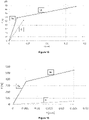
- the figure 9 thus highlights a modulation of rigidity of the flanges of configurations B, C, and D due to a modification of their active length or a modification of their points or their bearing surfaces when these are stressed, whether during assembly of the movement or during an impact of the watch case after assembly of the movement.
- the flange can be made of steel, in particular durnico steel.
- a shape memory alloy such as Nitinol, can advantageously be chosen for its superelastic properties.
- a flange formed from such an alloy has, in fact, the advantage of generating a force that varies significantly less than a flange made from a durnico steel beyond a given pre-stress threshold, and this due to the phase change of the material according to its rate of deformation according to the stresses it undergoes during fitting or that it is likely to undergo during an impact.
- This property is therefore particularly advantageous for mitigating as well as possible the variations in force induced by the variations in assembly configurations caused by the manufacturing and/or assembly tolerances of the movement and the case, and therefore makes it possible to propose a device for particularly robust assembly.
- a flange formed from such a superelastic alloy makes it possible to generate very substantial elastic restoring forces compared to those known from flanged fitting devices known from the prior art.
- the choice of such a material is therefore particularly advantageous with the aim of increasing the rigidity of the fitting, the advantages of which are those highlighted by studies of the plaintiff, and which are disclosed in the patent application EP2458456 , namely in particular a spectacular reduction in the acceleration undergone by the movement, for example during an impact on a hard surface.
- the invention also relates to a method of operating a fastening system which is the subject of the invention, in particular a method of operating the embodiments described above.
- the fastening system has an operation comprising a step of modifying the rigidity of the at least one flange, in particular modifying the bending rigidity of the at least one flange, when the movement is fixed and/or when the movement is moved relative to the watchcase element.
- the bent length of the at least one flange is modified, in particular the bent length of the at least one flange is reduced, when the movement is fixed and/or when the movement is moved relative to the element watchcase from a rest position in which the first surface 2b of the movement is in contact against the second surface 3b of the watchcase element.
- the timepiece 400 in particular a wristwatch, or the assembly 200 comprises a system 10 for fixing a watch movement 2 to an element 3 of the watch case 30, the system comprising at least one flange 1, in particular at least two flanges, preferably three flanges or four flanges, intended to come into contact with the movement on the one hand and with the watch case element on the other hand, the at least one flange being made of a superelastic alloy and/or of a shape memory alloy, in particular of a nickel-titanium alloy such as Nitinol.
- Nitinol is a superelastic, shape-memory alloy. Indeed, in a temperature range corresponding to the use which is made of the flanges (-10°C to 40°C for example), the Nitinol is in the austenitic phase, therefore superelastic.
- Nitinol is an alloy of Nickel and Titanium in which these two elements are present in approximately the same percentages, i.e. approximately 55% by weight or 60% by weight of Nickel and approximately 45% by weight or 40% by weight of titanium and possibly elements of addition in lesser proportion such as Chromium, Cobalt, or Niobium.
- Other shape memory alloys exist such as AuCd, CuAlBe, CuAINi or CuZnAl in monocrystalline or polycrystalline form.
- the alloys can also undergo special heat treatments to acquire their superelastic character.
- the 60NiTi alloy is nominally 60 wt% nickel and 40 wt% titanium.
- the 55NiTi alloy is nominally 55 wt% nickel and 45 wt% titanium.
- the Nitinol#1 alloy consists of 54.5% wt to 57.0% wt of nickel and between 43.0% wt and 45.5% wt of titanium with a maximum of 0.25% by weight of other elements such as chromium, cobalt, copper, iron or niobium in particular.
- Nitinol alloy having been the subject of studies, the results of which are represented on the figures 15 to 17 consists in particular of approximately 56% by weight of nickel and approximately 44% by weight of titanium and addition elements such as Cr, Cu and Fe.
- the CuAl12Be(0.45-0.68) alloy is nominally 12 wt% Aluminum and 0.45 wt% to 0.68 wt% Beryllium, with a balance of Copper.
- the CuAl13Ni4 alloy is nominally 83 wt% Copper, 13 wt% Aluminum and 4 wt% Nickel.
- the figure 15 illustrates a graph showing the evolution of the restoring force generated by two flanges in their elastic range, respectively made of durnico steel (curve 6) and Nitinol (curve 5a, 5b), according to their state of pre- "interference I" tension, once the movement is nested according to a configuration A.
- This graph shows a curve 5a, 5b comprising two distinct portions 5a, 5b of substantially different slopes, unlike curve 6 which has only one limited portion.
- the Nitinol flange is prestressed in such a way that it behaves according to the characteristic of the portion 5b of the curve.
- the variation in force produced by a Nitinol flange is minimized compared to that which is likely to produce a durnico steel flange.
- Nitinol flange In order to stiffen the casing as well as possible and to contain the superelastic nature of the alloy during the casing phase, the geometry of a Nitinol flange may evolve with respect to flanges known from the prior art.
- the thickness e of a Nitinol flange may, for example, be increased compared to that of a flange made of durnico steel, and/or the bending length Lf, constant or not depending on the stresses, may be minimized. .
- e ⁇ 0.5 mm for a Nitinol flange Preferably, e ⁇ 0.5 mm for a Nitinol flange.
- Lf ⁇ 1.35 mm for a Nitinol flange Preferably, Lf ⁇ 1.35 mm for a Nitinol flange.
- the figure 16 illustrates a graph showing the evolution of the restoring force generated respectively by two flanges in their elastic range, respectively made of durnico steel (curve 6) and Nitinol (curve 5a, 5b), according to their state of pre - "interference I" tension, once the movement is nested according to a configuration A.
- the figure 17 illustrates a graph showing the evolution of the restoring force generated respectively by two flanges in their elastic range, respectively made of durnico steel (curve 6) and Nitinol (curve 5a, 5b), according to their state of pre - "interference I" voltage, once the movement is interlocked according to a configuration A.
- Their “iso-constrained” geometry can be assimilated here to that of the figure 10 with a width L′ of greatest dimension of 2.05 mm.
- the system has the particularity of implementing a fitting that is particularly rigid and insensitive to variations in manufacturing and/or assembly tolerances.
- the active bending length Lf* of the flange corresponds to a limited portion of the total length L* of the flange.
- the length Lf* is in particular substantially less than the support length La* of the flange against the movement, in particular Lf* ⁇ La*/4.
- This length Lf* may turn out to be insufficient when assembling the movement in the case, which runs the risk of inducing residual deformation of the flange that could reduce the elastic restoring force potentially produced by said flange.
- This situation can in particular lead to the loss of contact between the surfaces 2b* and 3b*, which are respectively associated with the movement 2* and with the box 3*.
- This situation can also reduce the forces under the head of the screw 4*, which can lead to a risk of untimely unscrewing of said screw 4*.
- this length Lf* may then prove to be excessive once the movement is assembled in the case, in particular with regard to a predefined threshold of resistance to shocks and/or of a given amplitude of displacement of the movement, which also risks inducing a residual deformation of the flange which can reduce the elastic return force initially produced by said flange.
- the volume available at the interface of the movement and the case, the materials known from the prior art being able to be chosen to produce the flanges, cannot thus be sufficient to completely obviate the risks of residual plasticization of the said flanges at from a given shock threshold value.
- “superelastic alloy” is meant an alloy whose deformation at the elastic limit is greater than 2%, or even greater than 5%, or even greater than 8%.
Description
L'invention concerne un système de fixation d'un mouvement horloger à un élément de boîte de montre. L'invention concerne aussi un ensemble horloger comprenant un tel système. L'invention concerne encore une pièce d'horlogerie comprenant un tel système ou un tel ensemble. L'invention concerne enfin un procédé de fonctionnement d'un tel système ou d'un tel ensemble ou d'une telle pièce d'horlogerie.The invention relates to a system for attaching a watch movement to a watch case element. The invention also relates to a watch assembly comprising such a system. The invention also relates to a timepiece comprising such a system or such an assembly. The invention finally relates to a method of operating such a system or such an assembly or such a timepiece.
On emploie généralement deux ou trois brides d'emboîtage pour l'assemblage ou la fixation d'un mouvement horloger au sein d'une boîte de montre, notamment au sein d'une carrure.Two or three casing flanges are generally used for assembling or fixing a watch movement within a watch case, in particular within a middle part.
Lors de l'assemblage du mouvement au sein de la boîte, chaque bride d'emboîtage est insérée dans une découpe formée sur la circonférence interne de la carrure, puis fixée au mouvement par le biais d'un moyen de fixation.When assembling the movement within the case, each casing flange is inserted into a cutout formed on the internal circumference of the middle part, then fixed to the movement by means of a fixing means.
Cette découpe peut notamment être conformée de façon à ce que la bride puisse induire une force de précontrainte adéquate, qui permet de plaquer le mouvement à l'encontre de la carrure de la boîte afin de satisfaire des critères prédéfinis. Un critère peut, par exemple, être une minimisation de l'amplitude de débattement du mouvement pour une intensité donnée de choc, ainsi qu'une géométrie et un matériau donnés de bride, sans risque de plastification des brides.This cutout can in particular be shaped so that the flange can induce an adequate prestressing force, which makes it possible to press the movement against the middle of the case in order to satisfy predefined criteria. A criterion can, for example, be a minimization of the amplitude of displacement of the movement for a given intensity of impact, as well as a given geometry and material of flange, without risk of plasticization of the flanges.
Les
Toutefois, une telle solution peut poser des problèmes. Il existe en effet un risque de plastification des brides lors de l'assemblage et/ou sous l'effet d'un choc. Ceci peut conduire à une perte de contact non souhaitée du mouvement et de la carrure, voire à des risques de démontage non souhaités des brides.However, such a solution can cause problems. There is in fact a risk of plasticization of the flanges during assembly and/or under the effect of a shock. This can lead to an undesired loss of contact between the movement and the caseband, or even to the risk of undesired dismantling of the flanges.
Le document
Le document
Le but de l'invention est de fournir une pièce d'horlogerie comprenant un système de fixation d'un mouvement horloger dans une boîte de montre permettant de remédier aux inconvénients mentionnés précédemment et d'améliorer les dispositifs connus de l'art antérieur. En particulier, le système de fixation présente une fiabilité et une robustesse améliorées relativement aux systèmes connus de l'art antérieur.The object of the invention is to provide a timepiece comprising a system for fixing a timepiece movement in a watchcase making it possible to remedy the drawbacks mentioned above and to improve the known devices of the prior art. In particular, the fastening system has improved reliability and sturdiness compared to known systems of the prior art.
L'invention est définie par les revendications annexées.The invention is defined by the appended claims.
Selon un premier aspect, un système de fixation d'un mouvement horloger est déterminé par les définitions qui suivent.
- 1. Système de fixation d'un mouvement horloger à un élément de boîte de montre, le système comprenant :
- au moins une bride, en particulier au moins deux brides, de préférence trois brides ou quatre brides, destinée à venir en contact avec le mouvement d'une part et avec l'élément de boîte de montre d'autre part, et
- un dispositif de modification de la rigidité de l'au moins une bride, notamment de modification de la rigidité de flexion de l'au moins une bride, lorsque le mouvement est fixé et/ou déplacé relativement à l'élément de boîte de montre.
- 2. Système selon la
définition 1, caractérisé en ce que le dispositif de modification de la rigidité de l'au moins une bride est agencé de sorte que la longueur fléchie de l'au moins une bride est modifiée, notamment de sorte que la longueur fléchie de l'au moins une bride est diminuée, lorsque le mouvement est fixé à l'élément de boîte de montre ou déplacé relativement à l'élément de boîte de montre depuis une position de repos dans laquelle une première surface du mouvement est en contact contre une deuxième surface de l'élément de boîte. - 3. Système selon la
définition 1 ou 2, caractérisé en ce que l'appui ou le contact d'une première extrémité fléchie de l'au moins une bride à l'encontre du mouvement et/ou l'appui ou le contact d'une deuxième extrémité fléchie de l'au moins une bride à l'encontre de l'élément de boîte est (sont) modifié lorsque le mouvement est fixé à l'élément de boîte de montre ou déplacé relativement à l'élément de boîte de montre depuis une position de repos dans laquelle une première surface du mouvement est en contact contre une deuxième surface de l'élément de boîte. - 4. Système selon l'une des
définitions 1 à 3, caractérisé en ce que le dispositif de modification de la rigidité de l'au moins une bride comprend, à l'état fixé du mouvement à l'élément de boîte et le mouvement se trouvant en position de repos dans laquelle une première surface du mouvement est en contact contre une deuxième surface de l'élément de boîte, un premier jeu entre la bride et un point du mouvement contre lequel la bride peut venir en contact par flexion de la bride, la valeur du premier jeu étant inférieure à Lc1, voire inférieure à Lc1/3, voire inférieure à Lc1/4 et/ou la valeur du premier jeu est supérieure à Lc1/60, voire supérieure à Lc1/30, avec Lc1 étant la longueur d'une projection dans le plan du mouvement d'une troisième surface contre laquelle la bride peut venir en appui et la longueur Lc1 étant comprise entre Lf/10 et Lf avec Lf étant la longueur de bride fléchie, et/ou en ce que le dispositif de modification de la rigidité de l'au moins une bride comprend, à l'état fixé du mouvement à l'élément de boîte et le mouvement se trouvant en position de repos dans laquelle une première surface du mouvement est en contact contre une deuxième surface de l'élément de boîte, un deuxième jeu entre la bride et un point de l'élément de boîte contre lequel la bride peut venir en contact par flexion de la bride, la valeur du deuxième jeu étant inférieure à Lc2, voire inférieure à Lc2/3, voire inférieure à Lc2/4 et/ou la valeur du deuxième jeu est supérieure à Lc2/60, voire supérieure à Lc2/30, avec Lc2 étant la longueur d'une projection dans le plan du mouvement d'une cinquième surface contre laquelle la bride peut venir en appui et la longueur Lc2 étant comprise entre Lf/10 et Lf avec Lf mesurée à l'état de repos. - 5. Système selon l'une des
définitions 1 à 4, caractérisé en ce que le dispositif de modification de la rigidité de l'au moins une bride comprend :- une troisième surface formant un premier angle non nul avec un quatrième surface contre laquelle la bride est en appui lorsque le mouvement est dans une position de repos dans laquelle une première surface du mouvement est en contact contre une deuxième surface de l'élément de boîte, et/ou
- une cinquième surface formant un deuxième angle non nul avec une sixième surface contre laquelle la bride est en appui lorsque le mouvement est dans une position de repos dans laquelle une première surface du mouvement est en contact contre une deuxième surface de l'élément de boîte.
- 6. Système selon la définition 5, caractérisé en ce que le premier angle est inférieur à 45°, voire inférieur à 20°, voire inférieur à 15°, voire inférieur à 10° et/ou est supérieur à 1°, voire supérieur à 2° et/ou en ce que le deuxième angle est inférieur à 45°, voire inférieur à 20°, voire inférieur à 15°, voire inférieur à 10° et/ou est supérieur à 1°, voire supérieur à 2°.
- 7. Système selon la définition 5 ou 6, caractérisé en ce que la première surface est plane et/ou en ce que la deuxième surface est plane et/ou en ce que la troisième surface est plane et/ou en ce que la quatrième surface est plane et/ou en ce que la cinquième surface est plane et/ou en ce que la sixième surface est plane.
- 8. Système selon la définition 5 ou 6, caractérisé en ce que la troisième surface est bombée, notamment la troisième surface est une portion de cylindre, et/ou en ce que la cinquième surface est bombée, notamment la cinquième surface est une portion de cylindre.
- 9. Système selon l'une des
définitions 1 à 8, caractérisé en ce que l'au moins une bride comprend une section transversale dont le moment quadratique évolue selon un axe longitudinal, notamment par évolution de la largeur et/ou de l'épaisseur et/ou de sorte que la section transversale est telle que le profil des contraintes maximales est constant ou au moins sensiblement constant sur au moins une partie de la longueur de l'au moins une bride, notamment sur au moins la moitié de la longueur de ladite bride. - 10. Système selon l'une des
définitions 1 à 9, caractérisé en ce que l'au moins une bride est en un alliage superélastique et/ou en un alliage à mémoire de forme, notamment en un alliage nickel-titane tel que le Nitinol ou en ce que l'au moins une bride est en un alliage de nickel. - 11. Système selon l'une des
définitions 1 à 10, caractérisé en ce que l'au moins une bride comprend un élément de fixation au mouvement ou à l'élément de boîte, notamment un trou de passage de vis. Un ensemble horloger est déterminé par les définitions qui suivent. - 12. Ensemble horloger, notamment mouvement horloger et/ou élément de boîte de montre ou boîte de montre, comprenant un système selon l'une des
définitions 1 à 11. - 13. Ensemble horloger selon la
définition 12, caractérisé en ce que l'élément de boîte de montre est une carrure. - 14. Ensemble horloger selon la
définition 12 ou 13, caractérisé en ce que la troisième surface est réalisée sur le mouvement et/ou en ce que la quatrième surface est réalisée sur l'élément de boîte. - 15. Ensemble horloger selon la
définition 12 ou 13, caractérisé en ce que l'élément de boîte comprend un cercle d'emboîtage et/ou en ce que la quatrième surface est réalisée au moins en partie sur un cercle d'emboîtage ou en ce que le mouvement comprend un cercle d'emboîtage et/ou en ce que la troisième surface est réalisée au moins en partie sur un cercle d'emboîtage. Une pièce d'horlogerie est déterminée par la définition qui suit. - 16. Pièce d'horlogerie, notamment montre bracelet, comprenant un ensemble selon l'une des
définitions 12 à 15 et/ou ou un système selon l'une desdéfinitions 1 à 11. Un système de fixation d'un mouvement horloger est déterminé par les définitions qui suivent. - 17. Système de fixation d'un mouvement horloger à un élément de boîte de montre, le système comprenant au moins une bride, en particulier au moins deux brides, de préférence trois brides ou quatre brides, destinée à venir en contact avec le mouvement d'une part et avec l'élément de boîte de montre d'autre part, l'au moins une bride étant en un alliage superélastique et/ou en un alliage à mémoire de forme, notamment en un alliage nickel-titane tel que le Nitinol.
- 18. Système selon la définition 17, caractérisé en ce que l'au moins une bride comprend une section transversale dont le moment quadratique évolue selon un axe longitudinal, notamment par évolution de la largeur et/ou de l'épaisseur et/ou de sorte que la section transversale est telle que le profil des contraintes maximales est constant ou sensiblement constant sur au moins une partie de la longueur de l'au moins une bride, notamment sur au moins la moitié de la longueur de la bride.
- 19. Système selon l'une des définitions 17 à 18, caractérisé en ce que l'au moins une bride comprend un élément de fixation au mouvement ou à l'élément de boîte de montre, notamment un trou de passage de vis.
- 20. Système selon l'une des définitions 17 à 19, caractérisé en ce que l'épaisseur de l'au moins une bride est supérieure ou égale à 0,5 mm.
- 21. Système selon l'une des définitions 17 à 20, caractérisé en ce que la longueur fléchie de l'au moins une bride est inférieure ou égale à 1,35 mm. Un ensemble horloger est déterminé par la définition qui suit.
- 22. Ensemble horloger, notamment mouvement horloger ou élément de boîte de montre, comprenant un système selon l'une des définitions 17 à 21. Une pièce d'horlogerie est déterminée par la définition qui suit.
- 23. Pièce d'horlogerie, notamment montre bracelet, comprenant un ensemble selon la définition 22 et/ou ou un système selon l'une des définitions 17 à 21. Les figures annexées représentent, à titre d'exemples, deux modes de réalisation d'une pièce d'horlogerie selon l'invention.
- Les
figures 1 sont des vues en coupe d'un assemblage connu de l'art antérieur.et 2 - Les
figures 3 et 4 sont des vues d'un premier mode de réalisation d'une pièce d'horlogerie dans deux états. - Les
figures 5 et 6 sont des vues d'un deuxième mode de réalisation d'une pièce d'horlogerie dans deux états. - La
figure 7 est une vue en perspective de détail d'une première géométrie de bride pouvant être utilisée dans la pièce d'horlogerie selon l'invention. - La
figure 8 est un tableau récapitulatif illustrant le comportement de brides de même géométrie dans différents modes de réalisation. - La
figure 9 est un graphique illustrant les comportements de systèmes de de fixation de lafigure 8 lorsque le mouvement est déplacé relativement à la boîte. - La
figure 10 est une vue en perspective de détail d'une deuxième géométrie de bride pouvant être utilisée dans la pièce d'horlogerie selon l'invention. - La
figure 11 est une vue en coupe longitudinale d'une troisième géométrie de bride pouvant être utilisée dans la pièce d'horlogerie selon l'invention. - Les
figures 12 et13 sont des vues de détail d'exemples de géométries de surfaces de mouvement destinées à coopérer avec des brides. - La
figure 14 est une vue d'un troisième mode de réalisation d'une pièce d'horlogerie dans un état de repos. - Les
figures 15 à 17 sont des graphiques représentant des efforts de rappel d'un mouvement en fonction de son déplacement relativement à une boîte pour différents types de brides.
- 1. System for attaching a watch movement to an element of watch case, the system comprising:
- at least one flange, in particular at least two flanges, preferably three flanges or four flanges, intended to come into contact with the movement on the one hand and with the watch case element on the other hand, and
- a device for modifying the rigidity of the at least one flange, in particular for modifying the bending rigidity of the at least one flange, when the movement is fixed and/or moved relative to the watchcase element.
- 2. System according to
definition 1, characterized in that the device for modifying the rigidity of the at least one flange is arranged so that the bent length of the at least one flange is modified, in particular so that the length deflection of the at least one flange is reduced when the movement is fixed to the watch case element or moved relative to the watch case element from a rest position in which a first surface of the movement is in contact against a second surface of the box member. - 3. System according to
definition - 4. System according to one of definitions 1 to 3, characterized in that the device for modifying the rigidity of the at least one flange comprises, in the fixed state of the movement to the box element and the movement being in a rest position in which a first surface of the movement is in contact against a second surface of the case element, a first clearance between the flange and a point of the movement against which the flange can come into contact by bending of the flange , the value of the first set being less than Lc1, or even less than Lc1/3, or even less than Lc1/4 and/or the value of the first clearance is greater than Lc1/60, or even greater than Lc1/30, with Lc1 being the length of a projection in the plane of movement of a third surface against which the flange can come to bear and the length Lc1 being between Lf/10 and Lf with Lf being the length of flange deflected, and/or in that the device for modifying the stiffness of the at least one flange comprises, in the fixed state of the movement to the case element and the movement being in the rest position in which a first surface of the movement is in contact against a second surface of the box, a second clearance between the flange and a point of the box element against which the flange can come into contact by bending of the flange, the value of the second clearance being less than Lc2, or even less than Lc2/3, or even less at Lc2/4 and/or the value of the second game is higher than Lc2/60, or even higher re to Lc2/30, with Lc2 being the length of a projection in the plane of movement of a fifth surface against which the flange can bear and the length Lc2 being between Lf/10 and Lf with Lf measured at l state of rest.
- 5. System according to one of
definitions 1 to 4, characterized in that the device for modifying the rigidity of the at least one flange comprises:- a third surface forming a first non-zero angle with a fourth surface against which the flange bears when the movement is in a rest position in which a first surface of the movement is in contact against a second surface of the case element, and or
- a fifth surface forming a second non-zero angle with a sixth surface against which the flange bears when the movement is in a rest position in which a first surface of the movement is in contact against a second surface of the case element.
- 6. System according to definition 5, characterized in that the first angle is less than 45°, or even less than 20°, or even less than 15°, or even less than 10° and/or is greater than 1°, or even greater than 2° and/or in that the second angle is less than 45°, or even less than 20°, or even less than 15°, or even less than 10° and/or is greater than 1°, or even greater than 2°.
- 7. System according to
definition 5 or 6, characterized in that the first surface is planar and/or in that the second surface is planar and/or in that the third surface is planar and/or in that the fourth surface is planar and/or in that the fifth surface is planar and/or in that the sixth surface is planar. - 8. System according to
definition 5 or 6, characterized in that the third surface is curved, in particular the third surface is a portion of a cylinder, and/or in that the fifth surface is curved, in particular the fifth surface is a portion of cylinder. - 9. System according to one of
definitions 1 to 8, characterized in that the at least one flange comprises a cross section whose quadratic moment evolves along a longitudinal axis, in particular by evolution of the width and / or thickness and/or so that the cross-section is such that the profile of the maximum stresses is constant or at least substantially constant over at least part of the length of the at least one flange, in particular over at least half the length of said flange. - 10. System according to one of
definitions 1 to 9, characterized in that the at least one flange is made of a superelastic alloy and/or a shape memory alloy, in particular a nickel-titanium alloy such as Nitinol or in that the at least one flange is made of a nickel alloy. - 11. System according to one of
definitions 1 to 10, characterized in that the at least one flange comprises an element for fixing to the movement or to the case element, in particular a screw passage hole. A watch assembly is determined by the following definitions. - 12. Watch assembly, in particular watch movement and/or watch case element or watch case, comprising a system according to one of
definitions 1 to 11. - 13. Watch assembly according to
definition 12, characterized in that the watch case element is a middle part. - 14. Watch assembly according to
definition - 15. Watch assembly according to
definition - 16. Timepiece, in particular wristwatch, comprising an assembly according to one of
definitions 12 to 15 and/or a system according to one ofdefinitions 1 to 11. A system for fixing a watch movement is determined by the following definitions. - 17. System for fixing a watch movement to a watch case element, the system comprising at least one flange, in particular at least two flanges, preferably three flanges or four flanges, intended to come into contact with the movement of on the one hand and with the watchcase element on the other hand, the at least one flange being made of a superelastic alloy and/or of a shape memory alloy, in particular of a nickel-titanium alloy such as Nitinol .
- 18. System according to definition 17, characterized in that the at least one flange comprises a cross section whose quadratic moment changes along a longitudinal axis, in particular by changing the width and/or the thickness and/or so that the cross-section is such that the profile of the maximum stresses is constant or substantially constant over at least part of the length of the at least one flange, in particular over at least half the length of the flange.
- 19. System according to one of the definitions 17 to 18, characterized in that the at least one flange comprises an element for fixing to the movement or to the watchcase element, in particular a screw hole.
- 20. System according to one of definitions 17 to 19, characterized in that the thickness of the at least one flange is greater than or equal to 0.5 mm.
- 21. System according to one of definitions 17 to 20, characterized in that the bent length of the at least one flange is less than or equal to 1.35 mm. A watch assembly is determined by the following definition.
- 22. Timepiece assembly, in particular a timepiece movement or watch case element, comprising a system according to one of definitions 17 to 21. A timepiece is determined by the following definition.
- 23. Timepiece, in particular wristwatch, comprising an assembly according to definition 22 and/or a system according to one of definitions 17 to 21. The appended figures represent, by way of examples, two embodiments of a timepiece according to the invention.
- The
figures 1 and 2 are cross-sectional views of an assembly known from the prior art. - The
figure 3 and4 are views of a first embodiment of a timepiece in two states. - The
figure 5 and6 are views of a second embodiment of a timepiece in two states. - The
figure 7 is a detail perspective view of a first flange geometry that can be used in the timepiece according to the invention. - The
figure 8 is a summary table illustrating the behavior of flanges of the same geometry in different embodiments. - The
figure 9 is a graph illustrating the behaviors of fixation systems of thefigure 8 when the movement is moved relative to the box. - The
figure 10 is a detail perspective view of a second flange geometry that can be used in the timepiece according to the invention. - The
figure 11 is a view in longitudinal section of a third flange geometry that can be used in the timepiece according to the invention. - The
figure 12 and13 are detail views of examples of geometries of movement surfaces intended to cooperate with flanges. - The
figure 14 is a view of a third embodiment of a timepiece in a state of rest. - The
figures 15 to 17 are graphs representing restoring forces of a movement as a function of its displacement relative to a box for different types of flanges.
Un premier mode de réalisation d'une pièce d'horlogerie 400 est décrit ci-après en référence aux
Le mouvement horloger 2 et/ou un élément 3 de la boîte de montre et/ou la boîte 30 de montre peut constituer ou faire partie d'un ensemble horloger 200 comprenant ou prenant part à un système 10 de fixation du mouvement horloger 2 à l'élément 3 de boîte 30 de montre. L'élément de boîte de montre est une carrure ou un cercle d'agrandissement.The
Le système 10 de fixation du mouvement horloger 2 à l'élément 3 de boîte de montre comprend :
- au moins une
bride 1, en particulier au moins deux brides, de préférence trois brides ou quatre brides, destinée à venir en contact avec le mouvement d'une part et avec l'élément de boîte de montre d'autre part, et un dispositif 2a' de modification de la rigidité de l'au moins une bride, notamment de modification de la rigidité de flexion de l'au moins une bride, lors de la fixation du mouvement à l'élément de boîte et/ou lorsque le mouvement est déplacé relativement à l'élément de boîte de montre.
- at least one
flange 1, in particular at least two flanges, preferably three flanges or four flanges, intended to come into contact with the movement on the one hand and with the watch case element on the other hand, and - a
device 2a' for modifying the rigidity of the at least one flange, in particular for modifying the bending rigidity of the at least one flange, during the fixing of the movement to the element of case and/or when the movement is moved relative to the watch case element.
Le système présente la particularité de mettre en œuvre des brides d'emboîtage élastiques dont les rigidités sont susceptibles de varier en fonction des sollicitations qui leur sont appliquées, en particulier lors du déplacement du mouvement horloger en regard de la boîte de montre en cas de choc ou lors de l'assemblage du mouvement à la boîte. Selon un autre aspect, le système présente la particularité de mettre en œuvre un emboîtage particulièrement rigide et peu sensible aux variations de tolérances de fabrication et/ou d'assemblage. Une telle réalisation a pour avantage de proposer un système de fixation pérenne, qui obvie notamment aux risques de déformation plastique des brides prenant part à l'assemblage et/ou aux risques de démontage intempestif des moyens de fixation desdites brides, notamment en cas de choc de la montre.The system has the particularity of implementing elastic fitting flanges whose rigidities are likely to vary according to the stresses applied to them, in particular when the watch movement moves opposite the watch case in the event of an impact. or when assembling the movement to the case. According to another aspect, the system has the particularity of implementing a particularly rigid interlocking that is not very sensitive to variations in manufacturing and/or assembly tolerances. Such an embodiment has the advantage of proposing a permanent fastening system, which in particular obviates the risk of plastic deformation of the flanges taking part in the assembly and/or the risks of untimely dismantling of the fastening means of said flanges, in particular in the event of impact. of the watch.
La rigidité d'une bride peut être caractérisée par l'intensité de sa flèche suite à une sollicitation ou à un effort donné. Il est possible de moduler la rigidité d'une bride en modifiant sa longueur active et/ou en modifiant ses points ou surfaces d'appui lors de son chargement. Le dispositif de modification de la rigidité exploite cette possibilité.The rigidity of a flange can be characterized by the intensity of its deflection following a stress or a given effort. It is possible to modulate the rigidity of a flange by modifying its active length and/or by modifying its points or bearing surfaces during its loading. The stiffness modification device exploits this possibility.
Le dispositif de modification de la rigidité de l'au moins une bride est de préférence agencé de sorte que la longueur fléchie de l'au moins une bride est modifiée, notamment de sorte que la longueur fléchie de l'au moins une bride est diminuée, lorsque le mouvement est fixé à l'élément de boîte de montre ou déplacé relativement à l'élément de boîte de montre depuis une position de repos dans laquelle une première surface 2b du mouvement est en contact contre une deuxième surface 3b de l'élément de boîte. La première surface 2b est par exemple une face du mouvement. La deuxième surface 3b est par exemple une surface de portée réalisée dans la boîte, par exemple dans la carrure.The device for modifying the rigidity of the at least one flange is preferably arranged so that the bent length of the at least one flange is modified, in particular so that the bent length of the at least one flange is reduced , when the movement is fixed to the watchcase element or moved relative to the watchcase element from a rest position in which a
A l'état assemblé du mouvement dans la boîte, au moins une bride 1 est plaquée à l'encontre d'une surface 2A du mouvement. L'au moins une bride est en appui contre une surface 3A de la boîte, notamment contre une extrémité d'une surface 3A de la boîte. La surface 3A est par exemple une portée d'une découpe 31 ou d'un chambrage 31 réalisé dans l'élément de boîte, notamment dans la carrure. La bride 1 est ainsi déformée élastiquement lors de l'assemblage du mouvement de sorte à ce que la force de rappel élastique de la bride maintienne la surface 2b du mouvement 2 à l'encontre de la surface 3b de la boîte 3. La tenue de la bride sur le mouvement est ici assurée par une vis 4. La vis 4 est par exemple vissée dans un taraudage prévu dans le mouvement. La vis passe au travers d'un trou 14 pratiqué dans la bride 1. La tête de la vis est en appui à l'encontre d'une surface de la bride 1. Les première et deuxième surfaces 2b et 3b sont par exemple planes. Elles sont de préférence perpendiculaires à un axe A1 du mouvement. Cet axe A1 est perpendiculaire à un plan du mouvement, notamment à un plan d'un bâti du mouvement et/ou l'axe A1 est parallèle à la direction selon laquelle le mouvement est introduit dans l'élément 3 de boîte de montre.In the assembled state of the movement in the case, at least one
La longueur active de flexion Lf de la bride correspond à une portion limitée de la longueur totale L de la bride. La longueur active de flexion Lf s'étend entre une première zone formant une première extrémité 12 fléchie et une deuxième zone formant une deuxième extrémité fléchie 13. La première extrémité 12 se trouve à la limite de contact entre le mouvement et la bride. La deuxième extrémité 13 se trouve à la limite de contact entre la boîte et la bride. La longueur La est la longueur de la bride qui est en appui sur le mouvement. Cette longueur peut éventuellement être discontinue. Elle s'étend entre les limites extrêmes où la bride 1 est en appui sur le mouvement.The active bending length Lf of the flange corresponds to a limited portion of the total length L of the flange. The active bending length Lf extends between a first zone forming a first
Dans le premier mode de réalisation, la surface d'appui 2A du mouvement comporte au moins une portion 2a' de surface formant un angle α avec le bâti du mouvement. Cette portion 2a' est adjacente à une portion 2a contre laquelle la vis 4 plaque la bride à l'encontre du bâti du mouvement. La portion 2a est par exemple plane. Ainsi, la portion de surface 2a' forme l'angle α non nul avec la portion 2a contre laquelle la bride est en appui lorsque le mouvement est dans une position de repos dans laquelle la première surface 2b du mouvement est en contact contre la deuxième surface 3b de l'élément de boîte.In the first embodiment, the
Lors de l'assemblage du mouvement 2 au sein de la boîte 30, la bride 1 est déformée élastiquement par le contact avec tout ou partie de la surface 3A sous l'action de la vis 4. La bride est déformée élastiquement sur une distance axiale d'interférence correspondant à l'interférence de matière entre la bride et la boîte avant déformation élastique de la bride. Une fois le mouvement emboîté, la bride est plaquée à l'encontre de la surface 2A et maintenue en état de pré-tension par le biais de la vis 4. Dans les différentes configurations, la longueur de flexion Lf de la bride est notamment définie par la géométrie de la surface 2A. Au sein de la construction spécifique illustrée sur la
Lors du passage de la configuration de la
L'angle α est préférentiellement strictement inférieur à 45 °, voire inférieur à 20°, voire inférieur à 15°, voire inférieure à 10°. Cet angle α est préférentiellement supérieur à 1°, notamment supérieur à 2°. Ainsi, la portion 2a' doit être distinguée d'un simple chanfrein issu de la fabrication de la surface 2A. La portion 2a' peut, par ailleurs, occuper tout ou partie de la surface 2A.The angle α is preferably strictly less than 45°, or even less than 20°, or even less than 15°, or even less than 10°. This angle α is preferably greater than 1°, in particular greater than 2°. Thus, the
Bien entendu, il est possible de plaquer la bride à l'encontre de la portion 2a' dès l'assemblage, c'est-à-dire lors de l'assemblage ou lors de la fixation du mouvement au sein de la boîte, à savoir lorsque la distance d séparant le mouvement et la boîte est nulle. Une telle configuration a pour avantage d'augmenter la force de rappel produite par la bride dès l'assemblage du mouvement, et ce sans générer de contraintes susceptibles d'engendrer une déformation résiduelle de la bride.Of course, it is possible to press the flange against the
Ainsi, l'appui ou le contact de la première extrémité fléchie 12 de la bride à l'encontre du mouvement est modifié lorsque le mouvement est fixé à l'élément de boîte de montre ou déplacé relativement à l'élément de boîte de montre depuis une position de repos dans laquelle la première surface 2b du mouvement est en contact contre la deuxième surface 3b de l'élément de boîte.Thus, the support or the contact of the first
Dans ce premier mode de réalisation, le dispositif de modification de la rigidité de l'au moins une bride comprend la portion 2a'. La portion 2a' est par exemple plane.In this first embodiment, the device for modifying the rigidity of the at least one flange comprises the
Un deuxième mode de réalisation d'une pièce d'horlogerie 400 est décrit ci-après en référence aux
Dans le deuxième mode de réalisation, la surface d'appui 3A de la boîte comporte au moins une portion 3a' de surface formant un angle β avec le bâti du mouvement ou avec un plan perpendiculaire à l'axe A1 du mouvement. Cette portion 3a' est adjacente à une portion 3a contre laquelle la bride repose en position de repos du mouvement ou en cours de fixation du mouvement dans la boîte. La portion 3a est par exemple plane et est par exemple perpendiculaire à l'axe A1 du mouvement. Ainsi, la portion 3a' de surface 3A forme un angle β avec la portion 3a de surface 3A.In the second embodiment, the
Lors de l'assemblage du mouvement 2 au sein de la boîte 30, la bride 1 est déformée élastiquement par le contact avec tout ou partie de la surface 3A sous l'action de la vis 4. La bride est déformée élastiquement sur une distance axiale d'interférence correspondant à l'interférence de matière entre la bride et la boîte avant déformation élastique de la bride. Une fois le mouvement emboîté, la bride est plaquée à l'encontre de la surface 2A et maintenue en état de pré-tension par le biais de la vis 4. Dans les différentes configurations, la longueur de flexion Lf de la bride est notamment définie par la géométrie de la surface 3A. Au sein de la construction spécifique illustrée sur la
Lors du passage de la configuration de la
L'angle β est préférentiellement strictement inférieur à 45 °, voire inférieur à 20°, voire inférieur à 15°, voire inférieur à 10°. Cet angle β est préférentiellement supérieur à 1°, notamment supérieur à 2°. Ainsi, la portion 3a' doit être distinguée d'un simple chanfrein issu de la fabrication de la surface 3A. La portion 3a' peut, par ailleurs, occuper tout ou partie de la surface 3A.The angle β is preferably strictly less than 45°, or even less than 20°, or even less than 15°, or even less than 10°. This angle β is preferably greater than 1°, in particular greater than 2°. Thus, the
Bien entendu, il est possible de plaquer la bride à l'encontre de la portion 3a' dès l'assemblage du mouvement au sein de la boîte, à savoir lorsque la distance d séparant le mouvement et la boîte est nulle. Une telle configuration a pour avantage d'augmenter la force de rappel produite par la bride dès l'assemblage du mouvement, et ce sans générer de contraintes susceptibles d'engendrer une déformation résiduelle de la bride.Of course, it is possible to press the flange against the
Ainsi, l'appui ou le contact de la deuxième extrémité fléchie 13 de la bride à l'encontre de l'élément de boîte est modifié lorsque le mouvement est fixé à l'élément de boîte de montre ou déplacé relativement à l'élément de boîte de montre depuis une position de repos dans laquelle la première surface 2b du mouvement est en contact contre la deuxième surface 3b de l'élément de boîte.Thus, the support or the contact of the second
Dans ce deuxième mode de réalisation, le dispositif de modification de la rigidité de l'au moins une bride comprend la portion 3a'. La portion 3a' est par exemple plane.In this second embodiment, the device for modifying the rigidity of the at least one flange comprises the
Un troisième mode de réalisation d'une pièce d'horlogerie 400 est décrit ci-après. Ce mode est représenté sur la
Ainsi, l'appui ou le contact de la première extrémité fléchie 12 de la bride à l'encontre du mouvement et l'appui ou le contact de la deuxième extrémité fléchie 13 de la bride à l'encontre de l'élément de boîte sont modifiés lorsque le mouvement est fixé à l'élément de boîte de montre ou déplacé relativement à l'élément de boîte de montre depuis une position de repos dans laquelle la première surface 2b du mouvement est en contact contre la deuxième surface 3b de l'élément de boîte.Thus, the support or the contact of the first
Dans les différents modes de réalisation, un dispositif de modification de la rigidité de bride est avantageusement prévu au niveau de chaque bride. De préférence, dans une même pièce d'horlogerie, les dispositifs de modification de la rigidité de bride sont identiques pour chaque bride.In the various embodiments, a device for modifying the stiffness of the flange is advantageously provided at the level of each flange. Preferably, in the same timepiece, the flange stiffness modification devices are identical for each flange.
Chaque bride peut être de forme parallélépipédique ou sensiblement parallélépipédique comme représenté sur la
Avantageusement, une bride ou chaque bride comprend une section transversale S dont le moment quadratique évolue selon un axe longitudinal 11 de la bride.Advantageously, a flange or each flange comprises a cross section S whose quadratic moment evolves along a
Dans une première variante représentée sur la
Dans une deuxième variante représentée sur la
L'évolution de la largeur et/ou de l'épaisseur et/ou de la géométrie de la bride peut être telle que les sections transversales évoluent de sorte que le profil des contraintes maximales dans les sections est constant ou sensiblement constant au moins sur une partie de la longueur de la bride, notamment entre l'élément de fixation 14 et l'extrémité 15 de la bride, en particulier sur plus de la moitié de la portion s'étendant entre l'élément de fixation 14 et l'extrémité 15 de la bride. Autrement dit, la bride peut, notamment, présenter un profil d'égale résistance à la flexion ou «iso-contrainte». Plus généralement, les sections de la bride peuvent évoluer de façon à répartir au mieux les contraintes en son sein, et ainsi à les minimiser.The evolution of the width and/or the thickness and/or the geometry of the flange can be such that the cross-sections evolve so that the profile of the maximum stresses in the sections is constant or substantially constant at least over a part of the length of the flange, in particular between the fixing
Dans tous les modes de réalisation décrits plus haut, les portions 2a' ont été décrites comme réalisées sur le mouvement et les portions 3a' ont été décrites comme réalisées sur l'élément de boîte.In all the embodiments described above, the
Dans tous les modes de réalisation décrits plus haut, le mouvement est prévu pour être assemblé directement au sein d'une carrure. Toutefois, alternativement, le mouvement peut être assemblé sur un autre élément de boîte, comme notamment un fond ou une lunette, prévu pour être rapporté sur une carrure.In all the embodiments described above, the movement is designed to be assembled directly within a caseband. However, alternatively, the movement can be assembled on another case element, such as in particular a back or a bezel, provided to be attached to a middle part.
Bien entendu, l'ensemble horloger 200 peut également comprendre un cercle d'emboîtage ou cercle d'agrandissement, ce cercle d'emboîtage ou d'agrandissement pouvant être solidarisé au mouvement ou à la carrure par des moyens de fixation connexes. Dans une telle situation, les portions 2a' peuvent être réalisées au moins en partie sur le cercle d'emboîtage ou les portions 3a' peuvent être réalisées au moins en partie sur le cercle d'emboîtage.Of course, the
Dans tous les modes de réalisation décrits plus haut, les brides d'emboîtage ont été décrites fixées sur le mouvement. Alternativement, les moyens de fixation des brides peuvent être montés sur un cercle d'emboîtage. Alternativement encore, les moyens de fixation des brides peuvent être montés sur un élément de boîte, notamment sur une carrure.In all the embodiments described above, the casing flanges have been described fixed to the movement. Alternatively, the means for fixing the flanges can be mounted on a casing ring. Alternatively again, the means for fixing the flanges can be mounted on a case element, in particular on a middle part.
Dans tous les modes de réalisation décrits plus haut, les portions 2a' et 3a' ont été décrites comme des portions planes.In all the embodiments described above, the
Toutefois, alternativement, la portion 2a' et/ou la portion 3a' peut(vent) être convexe(s) ou bombée(s), notamment se présenter sous la forme d'une portion de cylindre, comme représenté sur la
Alternativement encore, la portion 2a' et/ou la portion 3a' peut(vent) être discontinue(s), notamment être formée(s) par un escalier, comme représenté sur la
Plus généralement, de préférence, à l'état fixé du mouvement à l'élément de boîte, le mouvement se trouvant en position de repos dans laquelle la première surface 2b du mouvement est en contact contre la deuxième surface 3b de l'élément de boîte, il peut exister un jeu e1 (
Plus généralement, de préférence, à l'état fixé du mouvement à l'élément de boîte, le mouvement se trouvant en position de repos dans laquelle la première surface 2b du mouvement est en contact contre la deuxième surface 3b de l'élément de boîte, il peut exister un jeu e2 (
Quelle que soit la variante de bride, chaque bride présente un élément de fixation 14 au mouvement ou à l'élément de boîte. Cet élément est par exemple un trou 14 de passage pour le passage d'une vis 4.Whatever the flange variant, each flange has a
Quelle que soit la variante de bride, la bride peut être réalisée en acier ou en un alliage superélastique et/ou en un alliage à mémoire de forme, notamment en un alliage nickel-titane tel que le Nitinol ou en un alliage de nickel.Whatever the flange variant, the flange can be made of steel or of a superelastic alloy and/or of a shape-memory alloy, in particular of a nickel-titanium alloy such as Nitinol or of a nickel alloy.
Quelle que soit la variante de bride, la bride 1 peut être plate ou non. Ainsi, la bride peut présenter une géométrie coudée. La bride 1 peut présenter un profil symétrique ou non.Regardless of the flange variant, the
La
La configuration A correspond à une configuration d'emboîtage selon l'art antérieur illustrée par les
La configuration B correspond à la configuration d'emboîtage du premier mode de réalisation illustrée par les
La configuration C correspond à la configuration d'emboîtage du deuxième mode de réalisation illustrée par les
La configuration D correspond à la configuration d'emboîtage du troisième mode de réalisation illustrée par la
On remarque que pour une même interférence I boîte - brides définissant une déformation élastique donnée des brides, les forces F de rappel élastique produites par les brides, suite à un choc d'une intensité donnée sur la pièce, varient sensiblement selon les configurations. Cela se traduit par des déplacements axiaux d des mouvements vis-à-vis de leur boîte respective, qui varient notablement, et donc des déformations résiduelles des brides Def qui peuvent subvenir de manière plus ou moins importante en fonction des configurations.It is noted that for the same box-flange interference I defining a given elastic deformation of the flanges, the elastic return forces F produced by the flanges, following an impact of a given intensity on the part, vary substantially according to the configurations. This results in axial displacements d of movements vis-à-vis their respective box, which vary significantly, and therefore residual deformations of the flanges Def which can occur to a greater or lesser extent depending on the configurations.
Le tableau de la
La
La
Comme vu précédemment, la bride peut être réalisée en acier, en particulier en acier durnico. Un alliage à mémoire de forme, comme le Nitinol, peut avantageusement être choisi pour ses propriétés superélastiques. Une bride formée en un tel alliage a, en effet, pour avantage de générer une force variant significativement moins qu'une bride réalisée en un acier durnico au-delà d'un seuil donné de précontrainte, et ce du fait du changement de phase du matériau selon son taux de déformation selon les sollicitations qu'elle subit lors de l'emboîtage ou qu'elle est susceptible de subir lors d'un choc. Cette propriété est donc particulièrement avantageuse pour pallier au mieux les variations de force induites par les variations de configurations d'assemblages causées par les tolérances de fabrication et/ou d'assemblage du mouvement et de la boîte, et permet donc de proposer un dispositif d'assemblage particulièrement robuste.As seen above, the flange can be made of steel, in particular durnico steel. A shape memory alloy, such as Nitinol, can advantageously be chosen for its superelastic properties. A flange formed from such an alloy has, in fact, the advantage of generating a force that varies significantly less than a flange made from a durnico steel beyond a given pre-stress threshold, and this due to the phase change of the material according to its rate of deformation according to the stresses it undergoes during fitting or that it is likely to undergo during an impact. This property is therefore particularly advantageous for mitigating as well as possible the variations in force induced by the variations in assembly configurations caused by the manufacturing and/or assembly tolerances of the movement and the case, and therefore makes it possible to propose a device for particularly robust assembly.
Par ailleurs, une bride formée en un tel alliage superélastique permet de générer des forces de rappel élastiques très conséquentes en regard de celles connues des dispositifs d'emboîtage à brides connus de l'art antérieur. Le choix d'un tel matériau est donc particulièrement avantageux dans le but d'augmenter la rigidité de l'emboîtage, dont les avantages sont ceux mis en évidence par le biais d'études de la demanderesse, et qui sont exposés dans la demande de brevet
L'invention porte aussi sur un procédé de fonctionnement d'un système de fixation objet de l'invention, notamment un procédé de fonctionnement des modes de réalisation décrits précédemment. Selon ce procédé de fonctionnement et/ou dans les différents modes de réalisation décrits précédemment, le système de fixation présente un fonctionnement comprenant une étape de modification de la rigidité de l'au moins une bride, notamment de modification de la rigidité de flexion de l'au moins une bride, lorsqu'on fixe le mouvement et/ou lorsqu'on déplace le mouvement relativement à l'élément de boîte de montre.The invention also relates to a method of operating a fastening system which is the subject of the invention, in particular a method of operating the embodiments described above. According to this operating method and/or in the various embodiments described above, the fastening system has an operation comprising a step of modifying the rigidity of the at least one flange, in particular modifying the bending rigidity of the at least one flange, when the movement is fixed and/or when the movement is moved relative to the watchcase element.
En particulier, on modifie la longueur fléchie de l'au moins une bride, notamment on diminue la longueur fléchie de l'au moins une bride, lorsqu'on fixe le mouvement et/ou lorsqu'on déplace le mouvement relativement à l'élément de boîte de montre depuis une position de repos dans laquelle la première surface 2b du mouvement est en contact contre la deuxième surface 3b de l'élément de boîte de montre.In particular, the bent length of the at least one flange is modified, in particular the bent length of the at least one flange is reduced, when the movement is fixed and/or when the movement is moved relative to the element watchcase from a rest position in which the
Ainsi, selon un deuxième aspect de l'invention, la pièce d'horlogerie 400, notamment une montre bracelet, ou l'ensemble 200 comprend un système 10 de fixation d'un mouvement horloger 2 à un élément 3 de boîte de montre 30, le système comprenant au moins une bride 1, en particulier au moins deux brides, de préférence trois brides ou quatre brides, destinée à venir en contact avec le mouvement d'une part et avec l'élément de boîte de montre d'autre part, l'au moins une bride étant en un alliage superélastique et/ou en un alliage à mémoire de forme, notamment en un alliage nickel-titane tel que le Nitinol.Thus, according to a second aspect of the invention, the
Le Nitinol est un alliage superélastique et à mémoire de forme. En effet, dans une plage de température correspondant à l'utilisation qui est faite des brides (-10°C à 40°C par exemple), le Nitinol est en phase austénitique, donc superélastique.Nitinol is a superelastic, shape-memory alloy. Indeed, in a temperature range corresponding to the use which is made of the flanges (-10°C to 40°C for example), the Nitinol is in the austenitic phase, therefore superelastic.
Le Nitinol est un alliage de Nickel et de Titane dans lequel ces deux éléments sont approximativement présents dans les mêmes pourcentages soit environ 55% pds ou 60% pds de Nickel et environ 45% pds ou 40% pds de titane et éventuellement des éléments d'addition en proportion moindre tels que le Chrome, le Cobalt, ou le Niobium. D'autres alliages à mémoire de forme existent tels que AuCd, CuAlBe, CuAINi ou CuZnAl sous forme monocristalline ou polycristalline.Nitinol is an alloy of Nickel and Titanium in which these two elements are present in approximately the same percentages, i.e. approximately 55% by weight or 60% by weight of Nickel and approximately 45% by weight or 40% by weight of titanium and possibly elements of addition in lesser proportion such as Chromium, Cobalt, or Niobium. Other shape memory alloys exist such as AuCd, CuAlBe, CuAINi or CuZnAl in monocrystalline or polycrystalline form.
Les alliages peuvent par ailleurs subir des traitements thermiques particuliers pour acquérir leur caractère de superélasticité.The alloys can also undergo special heat treatments to acquire their superelastic character.
Par exemple, l'alliage 60NiTi est constitué nominalement de 60%pds de nickel et 40%pds de titane. L'alliage 55NiTi est constitué nominalement de 55% pds de nickel et 45%pds de titane. L'alliage Nitinol#1 est constitué de 54.5% pds à 57.0% pds de nickel et entre 43.0% pds et 45.5% pds de titane avec au maximum 0.25%pds d'autres éléments tels que le chrome, le cobalt, le cuivre le fer ou le niobium notamment.For example, the 60NiTi alloy is nominally 60 wt% nickel and 40 wt% titanium. The 55NiTi alloy is nominally 55 wt% nickel and 45 wt% titanium. The
L'alliage de Nitinol ayant fait l'objet d'études dont les résultats sont représentés sur les
Par exemple, l'alliage CuAl12Be(0.45-0.68) est constitué nominalement de 12% pds d'Aluminium et de 0.45% pds à 0.68% pds de Beryllium, avec un solde de Cuivre.For example, the CuAl12Be(0.45-0.68) alloy is nominally 12 wt% Aluminum and 0.45 wt% to 0.68 wt% Beryllium, with a balance of Copper.
Par exemple, l'alliage CuAl13Ni4 est constitué nominalement de 83% pds de Cuivre, 13% pds d'Aluminium et de 4% pds de Nickel.For example, the CuAl13Ni4 alloy is nominally 83 wt% Copper, 13 wt% Aluminum and 4 wt% Nickel.
Tous les matériaux évoqués ci-dessus conviennent pour réaliser des brides.All the materials mentioned above are suitable for making flanges.
A titre d'exemple, la
Ce graphique fait état d'une courbe 5a, 5b comportant deux portions distinctes 5a, 5b de pentes sensiblement différentes, à la différence de la courbe 6 qui ne présente qu'une seule portion limitée. En configuration assemblée, la bride en Nitinol est précontrainte d'une telle manière qu'elle se comporte selon la caractéristique de la portion 5b de la courbe. Ainsi, pour une variation donnée d'interférence, la variation de force produite par une bride en Nitinol est minimisée en regard de celle qu'est susceptible de produire une bride en acier durnico.This graph shows a
Afin de rigidifier au mieux l'emboîtage et de contenir le caractère superélastique de l'alliage en phase d'emboîtage, la géométrie d'une bride en Nitinol pourra évoluer en regard des brides connues de l'art antérieur. L'épaisseur e d'une bride en Nitinol pourra, par exemple, être augmentée en regard de celle d'une bride faite en acier durnico, et/ou la longueur de flexion Lf, constante ou non en fonction des sollicitations, pourra être minimisée.In order to stiffen the casing as well as possible and to contain the superelastic nature of the alloy during the casing phase, the geometry of a Nitinol flange may evolve with respect to flanges known from the prior art. The thickness e of a Nitinol flange may, for example, be increased compared to that of a flange made of durnico steel, and/or the bending length Lf, constant or not depending on the stresses, may be minimized. .
Préférentiellement, e≥0,5 mm pour une bride en Nitinol.Preferably, e≥0.5 mm for a Nitinol flange.
Préférentiellement, Lf≤1,35 mm pour une bride en Nitinol.Preferably, Lf≤1.35 mm for a Nitinol flange.
A titre d'exemple, la
On remarque ici une force de rappel élastique considérablement augmentée en regard de celle produite par une bride en acier durnico, et ce sans risque de déformation résiduelle de la bride en Nitinol.We note here a considerably increased elastic restoring force compared to that produced by a durnico steel flange, and this without risk of residual deformation of the Nitinol flange.
Pour limiter l'augmentation d'épaisseur de la bride, on peut dans un même temps diminuer la longueur Lf de la bride. A titre d'exemple, la
On remarque également une force de rappel élastique considérablement augmentée en regard de celle produite par une bride en acier durnico, et ce sans risque de déformation résiduelle de la bride en Nitinol. Par ailleurs, pour une variation donnée d'interférence, la variation de force produite par une bride en Nitinol est minimisée en regard de celle qu'est susceptible de produire une bride en acier durnico. Ainsi, selon un deuxième aspect de l'invention, le système présente la particularité de mettre en œuvre un emboîtage particulièrement rigide et peu sensible aux variations de tolérances de fabrication et/ou d'assemblage.We also note a considerably increased elastic return force compared to that produced by a durnico steel flange, and this without risk of residual deformation of the Nitinol flange. Moreover, for a given interference variation, the variation in force produced by a Nitinol flange is minimized compared to that which is likely to produce a durnico steel flange. Thus, according to a second aspect of the invention, the system has the particularity of implementing a fitting that is particularly rigid and insensitive to variations in manufacturing and/or assembly tolerances.
Dans la réalisation connue de l'art antérieur et représenté sur les
A contrario, si la longueur Lf* est augmentée en regard de ces considérations, cette longueur Lf* peut alors s'avérer excessive une fois le mouvement assemblé dans la boîte, notamment en regard d'un seuil prédéfini de tenue aux chocs et/ou d'une amplitude donnée de déplacement du mouvement, ce qui risque également d'induire une déformation résiduelle de la bride pouvant amoindrir la force de rappel élastique initialement produite par ladite bride.On the other hand, if the length Lf* is increased with regard to these considerations, this length Lf* may then prove to be excessive once the movement is assembled in the case, in particular with regard to a predefined threshold of resistance to shocks and/or of a given amplitude of displacement of the movement, which also risks inducing a residual deformation of the flange which can reduce the elastic return force initially produced by said flange.
Ainsi, le volume à disposition au niveau de l'interface du mouvement et de la boîte, les matériaux connus de l'art antérieur pouvant être choisis pour réaliser les brides, ne peuvent ainsi suffire pour obvier totalement aux risques de plastification résiduelle desdites brides à partir d'une valeur seuil donnée de choc.Thus, the volume available at the interface of the movement and the case, the materials known from the prior art being able to be chosen to produce the flanges, cannot thus be sufficient to completely obviate the risks of residual plasticization of the said flanges at from a given shock threshold value.
Grâce aux solutions décrites dans ce document, ces problèmes peuvent être résolus et les systèmes de fixation peuvent être plus robustes et/ou plus fiables, du fait des matériaux utilisés pour les brides et/ou des géométries sur lesquelles reposent les brides. En effet, notamment selon des solutions décrites dans ce document les rigidités de brides élastiques d'emboîtage sont susceptibles de varier en fonction des sollicitations qui leur sont appliquées, en particulier en fonction du déplacement du mouvement horloger en regard de la boîte de montre, notamment lors de l'emboîtage et/ou lors d'un choc.Thanks to the solutions described in this document, these problems can be solved and the fastening systems can be more robust and/or more reliable, due to the materials used for the flanges and/or the geometries on which the flanges rest. Indeed, in particular according to the solutions described in this document, the rigidities of elastic casing flanges are likely to vary according to the stresses which are applied to them, in particular according to the displacement of the watch movement facing the watch case, in particular during fitting and/or during an impact.
Dans ce document, par "alliage superélastique", on entend un alliage dont la déformation à la limite élastique est supérieure à 2%, voire supérieure à 5%, voire supérieure à 8%.In this document, by "superelastic alloy" is meant an alloy whose deformation at the elastic limit is greater than 2%, or even greater than 5%, or even greater than 8%.
Dans ce document, les pourcentages en poids des éléments sont notés « % pds ».In this document, the percentages by weight of the elements are denoted “% wt”.
Claims (5)
- A timepiece (400), particularly a wristwatch, comprising:- a timepiece movement (2) having an axis (A1), a first flat surface (2b) that is perpendicular to the axis (A1) and a third surface (2A),- a watch case element (3) having a second flat bearing surface (3b) that is perpendicular to the axis (A1) and a fourth surface (3A), the watch case element being a middle or an enlarging ring, and- a system (10) for fixing the timepiece movement (2) to the watch case element (3),the system comprising:- at least two clamps (1), preferably three clamps or four clamps, which are intended to come into contact firstly with the movement and secondly with the watch case element, and- screws (4),the at least two clamps (1) being made of an alloy having a deformation at the elastic limit greater than 2%, or greater than 5%, or greater than 8%, the at least two clamps (1) being arranged to be elastically deformed when assembling the movement and to produce an elastic restoring force of each clamp holding the first surface (2b) against the second surface (3b), each clamp (1) being pressed against the third surface (2A) via one of said screws (4), under action of which each clamp bears against one said fourth surface (3A) of the watch case, notably a supporting area of a cutout (31) or of a recess (31) produced in the watch case element.
- The timepiece according to claim 1, wherein at least one of said clamps comprises a cross-section, the second moment of area of which changes along a longitudinal axis (11), particularly by change in the width and/or in the thickness and/or such that the cross-section is such that the profile of the maximum stresses is constant or substantially constant over at least part of the length of said clamp, particularly over at least half of the length of the clamp.
- The timepiece according to one of the preceding claims, wherein the at least one of said clamps comprises an element (14) for fixing to the movement or to the watch case element, particularly a screw (4) passage hole.
- The timepiece according to one of the preceding claims, wherein the thickness (e) of at least one of said clamps is greater than or equal to 0.5 mm.
- The timepiece according to one of the preceding claims, wherein the bent length (Lf) of at least one of said clamps is less than or equal to 1.35 mm.
Priority Applications (5)
| Application Number | Priority Date | Filing Date | Title |
|---|---|---|---|
| EP17201351.8A EP3483668B1 (en) | 2017-11-13 | 2017-11-13 | System for securing a clock movement in a watch case |
| US16/184,113 US11604436B2 (en) | 2017-11-13 | 2018-11-08 | System for fixing a timepiece movement in a watch case |
| US16/184,116 US11327442B2 (en) | 2017-11-13 | 2018-11-08 | System for fixing a timepiece movement in a watch case |
| CN201811348780.3A CN109782567A (en) | 2017-11-13 | 2018-11-13 | System for the fixed clock machine core in watchcase |
| JP2018212663A JP2019109226A (en) | 2017-11-13 | 2018-11-13 | System for fixing timepiece movement in small clock case |
Applications Claiming Priority (1)
| Application Number | Priority Date | Filing Date | Title |
|---|---|---|---|
| EP17201351.8A EP3483668B1 (en) | 2017-11-13 | 2017-11-13 | System for securing a clock movement in a watch case |
Publications (2)
| Publication Number | Publication Date |
|---|---|
| EP3483668A1 EP3483668A1 (en) | 2019-05-15 |
| EP3483668B1 true EP3483668B1 (en) | 2022-11-02 |
Family
ID=60301996
Family Applications (1)
| Application Number | Title | Priority Date | Filing Date |
|---|---|---|---|
| EP17201351.8A Active EP3483668B1 (en) | 2017-11-13 | 2017-11-13 | System for securing a clock movement in a watch case |
Country Status (3)
| Country | Link |
|---|---|
| EP (1) | EP3483668B1 (en) |
| JP (1) | JP2019109226A (en) |
| CN (1) | CN109782567A (en) |
Families Citing this family (1)
| Publication number | Priority date | Publication date | Assignee | Title |
|---|---|---|---|---|
| CN111772480B (en) * | 2020-07-09 | 2022-03-01 | 上海喆慧健康科技有限公司 | Powdery beverage brewing device |
Family Cites Families (12)
| Publication number | Priority date | Publication date | Assignee | Title |
|---|---|---|---|---|
| JPS4833328Y1 (en) * | 1969-08-25 | 1973-10-09 | ||
| JPS4989570A (en) * | 1972-12-26 | 1974-08-27 | ||
| DE2316784A1 (en) * | 1973-04-04 | 1974-10-17 | Kienhoefer & Moog Gmbh Kg | MOVEMENT RING FOR MOVEMENTS |
| JPS5573877U (en) * | 1978-11-16 | 1980-05-21 | ||
| JPH10288679A (en) * | 1997-04-15 | 1998-10-27 | Seiko Epson Corp | Thermal power generation type watch |
| JP2000111663A (en) * | 1998-09-30 | 2000-04-21 | Rhythm Watch Co Ltd | Frame installing structure and frame installing method |
| JP3610793B2 (en) * | 1998-11-26 | 2005-01-19 | セイコーエプソン株式会社 | Timing device |
| EP1182522A1 (en) * | 2000-08-22 | 2002-02-27 | Conseils et Manufactures VLG SA | Assembling device |
| JP2003344562A (en) * | 2002-05-30 | 2003-12-03 | Seiko Instruments Inc | Wristwatch |
| JP2008032418A (en) * | 2006-07-26 | 2008-02-14 | Seiko Instruments Inc | Wristwatch |
| JP4905815B2 (en) * | 2009-10-28 | 2012-03-28 | カシオ計算機株式会社 | Cushioning member, impact buffering structure of wristwatch, and wristwatch |
| EP2458456B1 (en) * | 2010-11-25 | 2020-03-18 | Rolex Sa | Watch with rigid casing and casing method |
-
2017
- 2017-11-13 EP EP17201351.8A patent/EP3483668B1/en active Active
-
2018
- 2018-11-13 CN CN201811348780.3A patent/CN109782567A/en active Pending
- 2018-11-13 JP JP2018212663A patent/JP2019109226A/en active Pending
Also Published As
| Publication number | Publication date |
|---|---|
| JP2019109226A (en) | 2019-07-04 |
| CN109782567A (en) | 2019-05-21 |
| EP3483668A1 (en) | 2019-05-15 |
Similar Documents
| Publication | Publication Date | Title |
|---|---|---|
| EP2674817B1 (en) | Manufacturing method of an arbour of a timepiece barrel | |
| EP3483667A1 (en) | System for securing a clock movement in a watch case | |
| EP2048548B1 (en) | Stricking mechanism | |
| EP2440085B1 (en) | Bracelet made up of articulated links | |
| EP2482144B1 (en) | Ratchet locking assembly system | |
| EP2693910B1 (en) | Watch strap strip | |
| EP2743781B1 (en) | Device for assembly by locking a joint | |
| EP2290476B1 (en) | Isochronism corrector for a timepiece escapement and an escapement equipped with such a corrector | |
| EP3451076B1 (en) | Stud-holder for a mechanical clockwork movement | |
| EP3483668B1 (en) | System for securing a clock movement in a watch case | |
| EP3182212A1 (en) | Composite part with resilient means under stress | |
| EP3257393B1 (en) | Screw for assembling two timepiece components | |
| EP3183618B1 (en) | Hand of a watch | |
| EP2798413B1 (en) | Spring for clock movement | |
| EP3736640B1 (en) | Clock balance | |
| US11327442B2 (en) | System for fixing a timepiece movement in a watch case | |
| EP3489766A1 (en) | Mechanism for correcting a function of a timepiece movement | |
| EP2643736B1 (en) | Watch with a rigid casing-up, and casing-up method | |
| EP3037893B1 (en) | Micromechanical or clock component with flexible guidance | |
| CH706645A1 (en) | Coupling system for coupling e.g. cog wheel with metal axle, in clockwork field, has plastically deformable material layer interposed between hole and axle and positioned to absorb plastic deformation related to driving operation | |
| EP2798414B1 (en) | Spring for clock movement | |
| EP3598241B1 (en) | Clock mechanism having a constant-force device | |
| EP3422117B1 (en) | Shock-absorber bearing for a shaft of a timepiece rotating componant | |
| EP3839656B1 (en) | Horological balance | |
| CH710007A2 (en) | Clock Hand. |
Legal Events
| Date | Code | Title | Description |
|---|---|---|---|
| PUAI | Public reference made under article 153(3) epc to a published international application that has entered the european phase |
Free format text: ORIGINAL CODE: 0009012 |
|
| STAA | Information on the status of an ep patent application or granted ep patent |
Free format text: STATUS: THE APPLICATION HAS BEEN PUBLISHED |
|
| AK | Designated contracting states |
Kind code of ref document: A1 Designated state(s): AL AT BE BG CH CY CZ DE DK EE ES FI FR GB GR HR HU IE IS IT LI LT LU LV MC MK MT NL NO PL PT RO RS SE SI SK SM TR |
|
| AX | Request for extension of the european patent |
Extension state: BA ME |
|
| STAA | Information on the status of an ep patent application or granted ep patent |
Free format text: STATUS: REQUEST FOR EXAMINATION WAS MADE |
|
| 17P | Request for examination filed |
Effective date: 20191114 |
|
| RBV | Designated contracting states (corrected) |
Designated state(s): AL AT BE BG CH CY CZ DE DK EE ES FI FR GB GR HR HU IE IS IT LI LT LU LV MC MK MT NL NO PL PT RO RS SE SI SK SM TR |
|
| RIN1 | Information on inventor provided before grant (corrected) |
Inventor name: REJZNER, JAMES Inventor name: CELANT, BENJAMIN Inventor name: JUNOD, BENOIT |
|
| STAA | Information on the status of an ep patent application or granted ep patent |
Free format text: STATUS: EXAMINATION IS IN PROGRESS |
|
| 17Q | First examination report despatched |
Effective date: 20200518 |
|
| STAA | Information on the status of an ep patent application or granted ep patent |
Free format text: STATUS: EXAMINATION IS IN PROGRESS |
|
| GRAP | Despatch of communication of intention to grant a patent |
Free format text: ORIGINAL CODE: EPIDOSNIGR1 |
|
| STAA | Information on the status of an ep patent application or granted ep patent |
Free format text: STATUS: GRANT OF PATENT IS INTENDED |
|
| INTG | Intention to grant announced |
Effective date: 20220517 |
|
| GRAS | Grant fee paid |
Free format text: ORIGINAL CODE: EPIDOSNIGR3 |
|
| GRAA | (expected) grant |
Free format text: ORIGINAL CODE: 0009210 |
|
| STAA | Information on the status of an ep patent application or granted ep patent |
Free format text: STATUS: THE PATENT HAS BEEN GRANTED |
|
| AK | Designated contracting states |
Kind code of ref document: B1 Designated state(s): AL AT BE BG CH CY CZ DE DK EE ES FI FR GB GR HR HU IE IS IT LI LT LU LV MC MK MT NL NO PL PT RO RS SE SI SK SM TR |
|
| REG | Reference to a national code |
Ref country code: GB Ref legal event code: FG4D Free format text: NOT ENGLISH |
|
| REG | Reference to a national code |
Ref country code: CH Ref legal event code: EP Ref country code: AT Ref legal event code: REF Ref document number: 1529191 Country of ref document: AT Kind code of ref document: T Effective date: 20221115 |
|
| REG | Reference to a national code |
Ref country code: DE Ref legal event code: R096 Ref document number: 602017063222 Country of ref document: DE |
|
| REG | Reference to a national code |
Ref country code: IE Ref legal event code: FG4D Free format text: LANGUAGE OF EP DOCUMENT: FRENCH |
|
| REG | Reference to a national code |
Ref country code: LT Ref legal event code: MG9D |
|
| REG | Reference to a national code |
Ref country code: NL Ref legal event code: MP Effective date: 20221102 |
|
| REG | Reference to a national code |
Ref country code: AT Ref legal event code: MK05 Ref document number: 1529191 Country of ref document: AT Kind code of ref document: T Effective date: 20221102 |
|
| PG25 | Lapsed in a contracting state [announced via postgrant information from national office to epo] |
Ref country code: SE Free format text: LAPSE BECAUSE OF FAILURE TO SUBMIT A TRANSLATION OF THE DESCRIPTION OR TO PAY THE FEE WITHIN THE PRESCRIBED TIME-LIMIT Effective date: 20221102 Ref country code: PT Free format text: LAPSE BECAUSE OF FAILURE TO SUBMIT A TRANSLATION OF THE DESCRIPTION OR TO PAY THE FEE WITHIN THE PRESCRIBED TIME-LIMIT Effective date: 20230302 Ref country code: NO Free format text: LAPSE BECAUSE OF FAILURE TO SUBMIT A TRANSLATION OF THE DESCRIPTION OR TO PAY THE FEE WITHIN THE PRESCRIBED TIME-LIMIT Effective date: 20230202 Ref country code: LT Free format text: LAPSE BECAUSE OF FAILURE TO SUBMIT A TRANSLATION OF THE DESCRIPTION OR TO PAY THE FEE WITHIN THE PRESCRIBED TIME-LIMIT Effective date: 20221102 Ref country code: FI Free format text: LAPSE BECAUSE OF FAILURE TO SUBMIT A TRANSLATION OF THE DESCRIPTION OR TO PAY THE FEE WITHIN THE PRESCRIBED TIME-LIMIT Effective date: 20221102 Ref country code: ES Free format text: LAPSE BECAUSE OF FAILURE TO SUBMIT A TRANSLATION OF THE DESCRIPTION OR TO PAY THE FEE WITHIN THE PRESCRIBED TIME-LIMIT Effective date: 20221102 Ref country code: AT Free format text: LAPSE BECAUSE OF FAILURE TO SUBMIT A TRANSLATION OF THE DESCRIPTION OR TO PAY THE FEE WITHIN THE PRESCRIBED TIME-LIMIT Effective date: 20221102 |
|
| PG25 | Lapsed in a contracting state [announced via postgrant information from national office to epo] |
Ref country code: RS Free format text: LAPSE BECAUSE OF FAILURE TO SUBMIT A TRANSLATION OF THE DESCRIPTION OR TO PAY THE FEE WITHIN THE PRESCRIBED TIME-LIMIT Effective date: 20221102 Ref country code: PL Free format text: LAPSE BECAUSE OF FAILURE TO SUBMIT A TRANSLATION OF THE DESCRIPTION OR TO PAY THE FEE WITHIN THE PRESCRIBED TIME-LIMIT Effective date: 20221102 Ref country code: LV Free format text: LAPSE BECAUSE OF FAILURE TO SUBMIT A TRANSLATION OF THE DESCRIPTION OR TO PAY THE FEE WITHIN THE PRESCRIBED TIME-LIMIT Effective date: 20221102 Ref country code: IS Free format text: LAPSE BECAUSE OF FAILURE TO SUBMIT A TRANSLATION OF THE DESCRIPTION OR TO PAY THE FEE WITHIN THE PRESCRIBED TIME-LIMIT Effective date: 20230302 Ref country code: HR Free format text: LAPSE BECAUSE OF FAILURE TO SUBMIT A TRANSLATION OF THE DESCRIPTION OR TO PAY THE FEE WITHIN THE PRESCRIBED TIME-LIMIT Effective date: 20221102 Ref country code: GR Free format text: LAPSE BECAUSE OF FAILURE TO SUBMIT A TRANSLATION OF THE DESCRIPTION OR TO PAY THE FEE WITHIN THE PRESCRIBED TIME-LIMIT Effective date: 20230203 |
|
| PG25 | Lapsed in a contracting state [announced via postgrant information from national office to epo] |
Ref country code: NL Free format text: LAPSE BECAUSE OF FAILURE TO SUBMIT A TRANSLATION OF THE DESCRIPTION OR TO PAY THE FEE WITHIN THE PRESCRIBED TIME-LIMIT Effective date: 20221102 |
|
| P01 | Opt-out of the competence of the unified patent court (upc) registered |
Effective date: 20230529 |
|
| REG | Reference to a national code |
Ref country code: BE Ref legal event code: MM Effective date: 20221130 |
|
| PG25 | Lapsed in a contracting state [announced via postgrant information from national office to epo] |
Ref country code: SM Free format text: LAPSE BECAUSE OF FAILURE TO SUBMIT A TRANSLATION OF THE DESCRIPTION OR TO PAY THE FEE WITHIN THE PRESCRIBED TIME-LIMIT Effective date: 20221102 Ref country code: RO Free format text: LAPSE BECAUSE OF FAILURE TO SUBMIT A TRANSLATION OF THE DESCRIPTION OR TO PAY THE FEE WITHIN THE PRESCRIBED TIME-LIMIT Effective date: 20221102 Ref country code: EE Free format text: LAPSE BECAUSE OF FAILURE TO SUBMIT A TRANSLATION OF THE DESCRIPTION OR TO PAY THE FEE WITHIN THE PRESCRIBED TIME-LIMIT Effective date: 20221102 Ref country code: DK Free format text: LAPSE BECAUSE OF FAILURE TO SUBMIT A TRANSLATION OF THE DESCRIPTION OR TO PAY THE FEE WITHIN THE PRESCRIBED TIME-LIMIT Effective date: 20221102 Ref country code: CZ Free format text: LAPSE BECAUSE OF FAILURE TO SUBMIT A TRANSLATION OF THE DESCRIPTION OR TO PAY THE FEE WITHIN THE PRESCRIBED TIME-LIMIT Effective date: 20221102 |
|
| REG | Reference to a national code |
Ref country code: DE Ref legal event code: R097 Ref document number: 602017063222 Country of ref document: DE |
|
| PG25 | Lapsed in a contracting state [announced via postgrant information from national office to epo] |
Ref country code: SK Free format text: LAPSE BECAUSE OF FAILURE TO SUBMIT A TRANSLATION OF THE DESCRIPTION OR TO PAY THE FEE WITHIN THE PRESCRIBED TIME-LIMIT Effective date: 20221102 Ref country code: LU Free format text: LAPSE BECAUSE OF NON-PAYMENT OF DUE FEES Effective date: 20221113 Ref country code: AL Free format text: LAPSE BECAUSE OF FAILURE TO SUBMIT A TRANSLATION OF THE DESCRIPTION OR TO PAY THE FEE WITHIN THE PRESCRIBED TIME-LIMIT Effective date: 20221102 |
|
| PLBE | No opposition filed within time limit |
Free format text: ORIGINAL CODE: 0009261 |
|
| STAA | Information on the status of an ep patent application or granted ep patent |
Free format text: STATUS: NO OPPOSITION FILED WITHIN TIME LIMIT |
|
| 26N | No opposition filed |
Effective date: 20230803 |
|
| PG25 | Lapsed in a contracting state [announced via postgrant information from national office to epo] |
Ref country code: IE Free format text: LAPSE BECAUSE OF NON-PAYMENT OF DUE FEES Effective date: 20221113 |
|
| PG25 | Lapsed in a contracting state [announced via postgrant information from national office to epo] |
Ref country code: SI Free format text: LAPSE BECAUSE OF FAILURE TO SUBMIT A TRANSLATION OF THE DESCRIPTION OR TO PAY THE FEE WITHIN THE PRESCRIBED TIME-LIMIT Effective date: 20221102 Ref country code: BE Free format text: LAPSE BECAUSE OF NON-PAYMENT OF DUE FEES Effective date: 20221130 |
|
| PGFP | Annual fee paid to national office [announced via postgrant information from national office to epo] |
Ref country code: GB Payment date: 20231120 Year of fee payment: 7 |
|
| PGFP | Annual fee paid to national office [announced via postgrant information from national office to epo] |
Ref country code: FR Payment date: 20231124 Year of fee payment: 7 Ref country code: DE Payment date: 20231107 Year of fee payment: 7 Ref country code: CH Payment date: 20231201 Year of fee payment: 7 |
|
| PG25 | Lapsed in a contracting state [announced via postgrant information from national office to epo] |
Ref country code: HU Free format text: LAPSE BECAUSE OF FAILURE TO SUBMIT A TRANSLATION OF THE DESCRIPTION OR TO PAY THE FEE WITHIN THE PRESCRIBED TIME-LIMIT; INVALID AB INITIO Effective date: 20171113 |