EP3483590B1 - Identifikations- und markierungssystem und -verfahren - Google Patents
Identifikations- und markierungssystem und -verfahren Download PDFInfo
- Publication number
- EP3483590B1 EP3483590B1 EP17200858.3A EP17200858A EP3483590B1 EP 3483590 B1 EP3483590 B1 EP 3483590B1 EP 17200858 A EP17200858 A EP 17200858A EP 3483590 B1 EP3483590 B1 EP 3483590B1
- Authority
- EP
- European Patent Office
- Prior art keywords
- tag
- dimensional
- encoding
- transmitter
- distribution
- Prior art date
- Legal status (The legal status is an assumption and is not a legal conclusion. Google has not performed a legal analysis and makes no representation as to the accuracy of the status listed.)
- Active
Links
Images
Classifications
-
- G—PHYSICS
- G01—MEASURING; TESTING
- G01N—INVESTIGATING OR ANALYSING MATERIALS BY DETERMINING THEIR CHEMICAL OR PHYSICAL PROPERTIES
- G01N21/00—Investigating or analysing materials by the use of optical means, i.e. using sub-millimetre waves, infrared, visible or ultraviolet light
- G01N21/17—Systems in which incident light is modified in accordance with the properties of the material investigated
- G01N21/25—Colour; Spectral properties, i.e. comparison of effect of material on the light at two or more different wavelengths or wavelength bands
- G01N21/31—Investigating relative effect of material at wavelengths characteristic of specific elements or molecules, e.g. atomic absorption spectrometry
- G01N21/35—Investigating relative effect of material at wavelengths characteristic of specific elements or molecules, e.g. atomic absorption spectrometry using infrared light
- G01N21/3581—Investigating relative effect of material at wavelengths characteristic of specific elements or molecules, e.g. atomic absorption spectrometry using infrared light using far infrared light; using Terahertz radiation
-
- G—PHYSICS
- G06—COMPUTING OR CALCULATING; COUNTING
- G06K—GRAPHICAL DATA READING; PRESENTATION OF DATA; RECORD CARRIERS; HANDLING RECORD CARRIERS
- G06K7/00—Methods or arrangements for sensing record carriers, e.g. for reading patterns
- G06K7/10—Methods or arrangements for sensing record carriers, e.g. for reading patterns by electromagnetic radiation, e.g. optical sensing; by corpuscular radiation
- G06K7/10009—Methods or arrangements for sensing record carriers, e.g. for reading patterns by electromagnetic radiation, e.g. optical sensing; by corpuscular radiation sensing by radiation using wavelengths larger than 0.1 mm, e.g. radio-waves or microwaves
-
- G—PHYSICS
- G01—MEASURING; TESTING
- G01N—INVESTIGATING OR ANALYSING MATERIALS BY DETERMINING THEIR CHEMICAL OR PHYSICAL PROPERTIES
- G01N21/00—Investigating or analysing materials by the use of optical means, i.e. using sub-millimetre waves, infrared, visible or ultraviolet light
- G01N21/17—Systems in which incident light is modified in accordance with the properties of the material investigated
- G01N21/25—Colour; Spectral properties, i.e. comparison of effect of material on the light at two or more different wavelengths or wavelength bands
- G01N21/31—Investigating relative effect of material at wavelengths characteristic of specific elements or molecules, e.g. atomic absorption spectrometry
- G01N21/35—Investigating relative effect of material at wavelengths characteristic of specific elements or molecules, e.g. atomic absorption spectrometry using infrared light
- G01N21/3581—Investigating relative effect of material at wavelengths characteristic of specific elements or molecules, e.g. atomic absorption spectrometry using infrared light using far infrared light; using Terahertz radiation
- G01N21/3586—Investigating relative effect of material at wavelengths characteristic of specific elements or molecules, e.g. atomic absorption spectrometry using infrared light using far infrared light; using Terahertz radiation by Terahertz time domain spectroscopy [THz-TDS]
Definitions
- the present invention relates to an identification and tagging system and method. Further, the present invention also relates to a tag for use in such a system and method.
- Terahertz radiation is considered radiation in the spectral region of 0.1 to 10 THz (wavelengths of approximately 3 mm to 30 ⁇ m).
- THz radiation For use in tagging applications THz radiation has some general advantages as compared to other parts of the electromagnetic spectrum. Other than visible or infrared waves, THz radiation can penetrate into organic materials such as fabrics or plastics. On the other hand, THz radiation does not cause any damage associated with X-rays or other ionizing radiation, as the photon energy involved is relatively low.
- US 2015/0170013 A1 discloses a process of encoding information in a volumetric tag inside a three dimensional physical object during manufacture thereof and reading the encoded information using a terahertz (THz) imaging reader.
- the encoded information is read by emitting a pulse of THz radiation toward the tagged object and measuring the reflected pulse from material interfaces resulting from the use of materials with a (relative to each other) high or low respective refractive index.
- materials with a (relative to each other) high or low respective refractive index For example, polystyrene (PS) and high density polyethylene (HDPE) are used as materials with different refractive properties for encoding and ABS is used as an enclosure material.
- PS polystyrene
- HDPE high density polyethylene
- Other suitable encoding materials as well as manufacturing methods are also disclosed in US 2015/0170013 A1 .
- a reader employed in a system of the above prior art can only read one tag at a time, wherein the angle of orientation of the reader relative to the tag is required to be within a given range.
- THz tags are disclosed in US2010/148050 A1 , which suggests a THz tagging/ identification method based on measuring the presence/absence of refracted, diffracted or dispersed radiation, or in US 2015/170013 A1 and US 2006/231625 A1 , which disclose a method for encoding information in a volumetric tag comprising a three dimensional, locally differing distribution of at least one encoding material and reading the encoded information using a THz imaging reader.
- a method for reading information encoded by a three-dimensional, locally differing distribution of at least one encoding material is provided, wherein respective transmission spectra of said three-dimensional tag are determined in a frequency band ranging above 0.1 THz in plural, preferably six or more, more preferably 36 or more, respective spatial directions.
- the frequency band has a lower limit of 0.1 THz or higher and an upper limit of more than 0.1 THz, preferably less than 10 THz.
- tags to be read are generally oriented in essentially the same manner, such as at a conveyor belt, as well as applications in which tags to be read are generally oriented in a random manner.
- the of spatial directions can be varied depending on the materials, tag size, resolution etc. in order to create distinct transmission profiles from different angles.
- the inventive method allows to determine transmission spectra of more than one tags simultaneously.
- a tag comprising at least three encoding materials having a respective attenuation coefficient different from one another is used as said three-dimensional tag.
- a three-dimensional tag comprising at least three encoding materials having a respective attenuation coefficient different from one another.
- the tag has an essentially cubic shape.
- essentially cubic means a shape with six surfaces in three essentially orthogonal spatial directions.
- the tag comprises an enclosure material having an attenuation coefficient different from the encoding materials.
- Tags according to or used for implementations of the present invention can be manufactured using, as encoding materials, a wide variety of materials known per se from the prior art for use in connection with THz applications, such as various crystal materials (e.g. silicon, crystal quartz, and sapphire) and polymers (e.g. polymethylpentene [TPX], polyethylene [PE], polypropylene [PP], and polytetrafluoroethylene [PTFE]).
- various crystal materials e.g. silicon, crystal quartz, and sapphire
- polymers e.g. polymethylpentene [TPX], polyethylene [PE], polypropylene [PP], and polytetrafluoroethylene [PTFE]
- the present invention provides a tagging and identification method wherein an item is tagged by providing the item with a three-dimensional, locally differing distribution of at least one encoding material thus defining a three-dimensional tag, and the encoded information is read according to the above described inventive method thereby identifying the tagged item.
- the present invention provides a system for reading information encoded by a three-dimensional, locally differing distribution of at least one encoding material thus defining a three-dimensional tag, wherein the system comprises plural, preferably six or more, more preferably 36 or more, transmitter-receiver pairs configured for determining respective transmission spectra in a frequency band ranging above 0.1 THz of said three-dimensional tag in a plurality of respective spatial directions, and computing means for retrieving the information from the transmission spectra.
- an essentially spherical arrangement can be set up such that transmitter and receiver pairs are located on opposite surfaces of a sphere along the surface of the sphere. This allows simultaneous scanning to achieve a volumetric image of the tag(s) positioned inside this sphere at an instant.
- THz imaging devices as known per se for example from Savage, V., Schmidt, R., Grossman, T., Fitzmaurice, G., and Hartmann, B., "A series of tubes: adding interactivity to 3D prints using internal pipes.” In Proceedings of the 27th annual ACM symposium on User interface software and technology (October 2014), 3-12 can be utilized for implementations of the present invention.
- the prior allows only reading one tag at a time with single scanner, as the known systems are based on reflected waves requiring a line of sight path between the transmitter and tag, the present invention based on transmission techniques allows to read more than one tag at a time: It is possible to detect multiple tags at the same time with a single scan.
- the present invention further allows encoding data using a 3D distribution of defects throughout the preferably cubic tag compared with 1D THz tags of the prior art. Therefore, by implementing the present invention the data storage capacity can be improved by three orders of magnitude for a given tag size. Moreover, the invention allows implementation of slice based transmission throughout the tag further improving the identification capability and also further improving the data storage capacity by coding slice based data in addition to the relative position of the defects distributed throughout the tag.
- slices correspond to beams which we can be assume to resemble focused Gaussian beams. However, they are in spherical coordinates.
- the optical properties, in the relevant frequency band, of the materials change at different temperatures, the attenuation coefficients will change and they will result in different readings.
- the following degrees of freedom for transmission based reading architecture can be taken advantage of: First, the combinations of different materials at a specific set of spherical angles result in different absorption ratios. Second, the absorption changes at different frequencies in a range of, for example, 0.1-10 THz. Third, the absorption coefficients change at different temperatures.
- the present invention thus allows substantially limitless variations of tags in order to enrich the type of the received waveforms, i.e. the signatures of different tags.
- TDS Time Domain Spectroscopy
- the present invention can also be advantageously implemented using a spectral encoding approach as described in Bernier, M., Garet, F., Perret, E., Duvillaret, L., and Tedjini, S. "Terahertz encoding approach for secured chipless radio frequency identification” Applied optics 50(23) (2011), 4648-4655 , by checking the resonance frequency changes due to defects in the volume.
- the number of materials can be much higher than in the prior art since the reflection and the reflection angle are not major concerns but the transmission is important, which allows more flexibility in the design.
- s the input radiation intensity
- abscoeff the material absorption coefficient
- thickness the thickness of the material
- Evaluation of the measurements can be advantageously based on pre-extracting signatures of different combinations of tag materials at different angles (e.g. 36 different angles for 6 different tagging materials in various positions inside a spherical tag) and building a table or waveform library thereof.
- the sampled data is correlated with respective elements of the library and the decoding is realized according to a maximum likelihood algorithm known per se from the prior art (least square method, fuzzy logic algorithm or the like).
- a maximum likelihood algorithm known per se from the prior art (least square method, fuzzy logic algorithm or the like).
- any of the embodiments described or options mentioned herein may be particularly advantageous depending on the actual conditions of application. Further, features of one embodiment may be combined with features of another embodiment as far as technically possible and unless indicated otherwise.
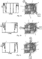
- FIG. 1a-1c depicts a tag 1 including four encoding materials 2, 3, 4 and 5 with locally differing three-dimensional distributions. All four encoding materials 2, 3, 4 and 5 have a respective attenuation coefficient different from one another, such that they allow a different transmission of radiation of a frequency in the Terahertz range (0.1 THz through 10 THz).
- the encoding materials 2, 3, 4 and 5 are enclosed in the enclosure material 6, e.g. a suitable resin material, having a transmittance for radiation of a frequency in the Terahertz range higher than the encoding materials 2, 3, 4 and 5.
- the purpose of the enclosure material 6 is protecting the encoding materials 2, 3, 4 and 5 from physical damage.
- a respective pair of transmitter TX and receiver RX is used for determining a respective transmission spectrum 7.
- the optical axes of the respective transmitter receiver pairs TX, RX are oriented at different angles relative to a reference plane (e.g. a surface plane) of the tag 1.
- the resulting transmission spectra 7 are different for different optical axes, as the distribution of encoding materials 2, 3, 4 and 5 along the respective transmission paths of radiation through the tag 1 is different from axis to axis.
- the locally different distribution of encoding materials 2, 3, 4 and 5 makes it possible to encode information on the tag 1 which is identifiable due to a unique signature of resulting transmission spectra 7 as explained above.
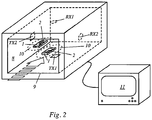
- the reader system depicted in Fig. 2 comprises a reader chamber 8 configured to receive, through the opening 9, items 10 tagged with respective tags 1, as indicated by the arrow symbolizing front access of the chamber 8.
- At least one, preferably more encoding materials 2 are distributed three-dimensionally in a locally differing manner in order to produce a unique signature of THz transmission spectra.
- a plurality of transmitter receiver pairs TX, RX are arranged defining a plurality of optical axes, respectively.
- the transmitter receiver pairs only a first transmitter receiver pairs TX1, RX1 and a second transmitter receiver pair TX2, RX2 are depicted, the optical axes of which are orthogonal relative to each other.
- All transmitter receiver pairs TX1, RX1, TX2, RX2 operate in a THz range (0.1 THz to 10 THz).
- the reader chamber 8 is connected to a computer 11 for evaluating receiver signals from the receivers RX1, RX2 in order to retrieve encoded information from transmission spectra represented by the receiver signals.
- the computer 11 has stored therein a database of pre-extracting signatures of different combinations of encoding materials 2 at different angles relative to the optical axes of the transmitter receiver pairs TX1, RX1, TX2, RX2. Whenever a reading is made by the receivers RX1, RX2 for identifying a tag 2, the computer 11 correlates receiver signals with respective elements of the database and thus decodes the tags 1 according to a maximum likelihood algorithm.
- a reference reader chamber like the reader chamber depicted in Fig. 2 can be used and multiple different tag templates can be scanned by transmitter receiver pairs TX1, RX1, TX2, RX2 of the reference reader chamber in order to create receiver signals that can be stored as respective signatures.
- the optical axes of respective transmitter receiver pairs are oriented at different angles relative to a reference plane (e.g. a surface plane) of the tag 1.
- the resulting transmission spectra 7 are different for different optical axes, as the distribution of encoding materials 2, 3, 4, 5 along the respective transmission paths of radiation through the tag 1 is different from axis to axis.
- Tag 10 Tagged item 2
- First encoding material 11 Computer 3
- Second encoding material TX Transmitter 4
- Third encoding material RX Receiver 5
- Fourth encoding material TX1 Transmitter of first pair 6
- Enclosure material RX1 Receiver of first pair 7 Transmission spectrum
- TX2 Transmitter of second pair 8 Reader chamber RX2 Receiver of second pair 9 Opening
Landscapes
- Physics & Mathematics (AREA)
- Health & Medical Sciences (AREA)
- Toxicology (AREA)
- General Physics & Mathematics (AREA)
- General Health & Medical Sciences (AREA)
- Engineering & Computer Science (AREA)
- Spectroscopy & Molecular Physics (AREA)
- Computer Vision & Pattern Recognition (AREA)
- Electromagnetism (AREA)
- Theoretical Computer Science (AREA)
- Artificial Intelligence (AREA)
- Life Sciences & Earth Sciences (AREA)
- Chemical & Material Sciences (AREA)
- Analytical Chemistry (AREA)
- Biochemistry (AREA)
- Immunology (AREA)
- Pathology (AREA)
- Radar Systems Or Details Thereof (AREA)
Claims (13)
- Verfahren zum Lesen von Informationen, die durch eine lokal unterschiedliche Verteilung von mindestens einem Kodiermaterial (2, 3, 4, 5) kodiert sind, wodurch ein Kennzeichen (1) definiert ist,wobei das Verfahren die Bestimmung eines Übertragungsspektrums (7) des Kennzeichens (1) in einem Frequenzband oberhalb von 0,1 THz umfasst,dadurch gekennzeichnet, dassdie lokal unterschiedliche Verteilung eine dreidimensionale Verteilung des mindestens einen Kodiermaterials (2, 3, 4, 5) ist,das Kennzeichen (1) ein dreidimensionales Kennzeichen (1) ist, unddas Verfahren das Bestimmen jeweiliger Übertragungsspektren (7) einschließlich des Übertragungsspektrums (7) in mehreren jeweiligen Raumrichtungen unter Verwendung jeweiliger Sender-Empfänger-Paare (TX1, RX1, TX2, RX2) aufweist.
- Verfahren gemäß Anspruch 1, wobei die Übertragungsspektren (7) in mindestens 6 verschiedenen Raumrichtungen bestimmt werden.
- Verfahren gemäß Anspruch 2, bei dem die Übertragungsspektren (7) in mindestens 36 verschiedenen Raumrichtungen bestimmt werden.
- Verfahren gemäß einem der Ansprüche 1 bis 3, wobei die Transmissionsspektren (7) von mehr als einem Kennzeichen (1) gleichzeitig bestimmt werden.
- Verfahren nach einem der Ansprüche 1 bis 4, wobei als dreidimensionales Kennzeichen (1) ein Kennzeichen (1) verwendet wird, das mindestens drei Kodiermaterialien (2, 3, 4, 5) aufweist, die jeweils einen voneinander verschiedenen Dämpfungskoeffizienten aufweisen.
- Verfahren zur Kennzeichnung und Identifizierung, umfassendKennzeichnen eines Gegenstandes (10) durch Versehen des Gegenstandes mit einer lokal unterschiedlichen Verteilung von mindestens einem Kodiermaterial (2, 3, 4, 5), wodurch ein Kennzeichen (1) definiert wird,dadurch gekennzeichnet, dassdie lokal unterschiedliche Verteilung eine dreidimensionale Verteilung des mindestens einen Kodiermaterials (2, 3, 4, 5) ist,das Kennzeichen (1) ein dreidimensionales Kennzeichen (1) ist, und
das Kennzeichnungs- und Identifizierungsverfahren des Weiteren aufweistdas Lesen der kodierten Information gemäß dem Verfahren gemäß einem der Ansprüche 1-4, wodurch der gekennzeichnete Gegenstand (10) identifiziert wird. - Verfahren zur Kennzeichnung und Identifizierung gemäß Anspruch 6,
wobei der Gegenstand (10) mit einer dreidimensionalen, lokal unterschiedlichen Verteilung von mindestens drei Kodiermaterialien (2, 3, 4, 5) versehen ist, die einen jeweils voneinander abweichenden Dämpfungskoeffizienten aufweisen. - System zum Lesen von Informationen, die durch eine lokal unterschiedliche Verteilung mindestens eines Kodiermaterials (2, 3, 4, 5) kodiert sind und so ein Kennzeichen (1) definieren,wobei das System umfasstein Sender-Empfänger-Paar, das so konfiguriert ist, dass es ein Übertragungsspektrum des Kennzeichens (1) in einem Frequenzband von über 0,1 THz bestimmt,dadurch gekennzeichnet, dass
die lokal unterschiedliche Verteilung eine dreidimensionale Verteilung des mindestens einen Kodiermaterials (2, 3, 4, 5) ist,das Kennzeichen (1) ein dreidimensionales Kennzeichen (1) ist, unddass das System mehrere Sender-Empfänger-Paare (TX1, RX1, TX2, RX2) einschließlich des Sender-Empfänger-Paares aufweist, die zum Bestimmen jeweiliger Übertragungsspektren (7) einschließlich des Übertragungsspektrums (7) in mehreren jeweiligen Raumrichtungen konfiguriert sind, undRechenmittel (11), die so konfiguriert sind, dass sie die in dem dreidimensionalen Kennzeichen (1) kodierten Informationen aus den Übertragungsspektren (7) abrufen. - System gemäß Anspruch 8, wobei die mehreren Sender-Empfänger-Paare (TX1, RX1, TX2, RX2) mindestens 6 Sender-Empfänger-Paare (TX1, RX1, TX2, RX2) umfassen.
- System gemäß Anspruch 9, wobei die mehreren Sender-Empfänger-Paare (TX1, RX1, TX2, RX2) mindestens 36 Sender-Empfänger-Paare (TX1, RX1, TX2, RX2) umfassen.
- Dreidimensionales Kennzeichen (1) mit einer lokal unterschiedlichen Verteilung von mindestens drei Kodiermaterialien (2, 3, 4, 5), die einen jeweils voneinander verschiedenen Dämpfungskoeffizienten aufweisen, zur Verwendung im Verfahren nach Anspruch 5.
- Dreidimensionales Kennzeichen (1) gemäß Anspruch 11, wobei das Kennzeichen (1) eine im wesentlichen kubische Form aufweist.
- Dreidimensionales Kennzeichen (1) gemäß Anspruch 11 oder Anspruch 12, das ferner ein Umhüllungsmaterial (6) mit einem jeweils von den Codierungsmaterialien (2, 3, 4, 5) verschiedenen Dämpfungskoeffizienten aufweist.
Priority Applications (1)
| Application Number | Priority Date | Filing Date | Title |
|---|---|---|---|
| EP17200858.3A EP3483590B1 (de) | 2017-11-09 | 2017-11-09 | Identifikations- und markierungssystem und -verfahren |
Applications Claiming Priority (1)
| Application Number | Priority Date | Filing Date | Title |
|---|---|---|---|
| EP17200858.3A EP3483590B1 (de) | 2017-11-09 | 2017-11-09 | Identifikations- und markierungssystem und -verfahren |
Publications (2)
| Publication Number | Publication Date |
|---|---|
| EP3483590A1 EP3483590A1 (de) | 2019-05-15 |
| EP3483590B1 true EP3483590B1 (de) | 2022-01-12 |
Family
ID=60382039
Family Applications (1)
| Application Number | Title | Priority Date | Filing Date |
|---|---|---|---|
| EP17200858.3A Active EP3483590B1 (de) | 2017-11-09 | 2017-11-09 | Identifikations- und markierungssystem und -verfahren |
Country Status (1)
| Country | Link |
|---|---|
| EP (1) | EP3483590B1 (de) |
Families Citing this family (1)
| Publication number | Priority date | Publication date | Assignee | Title |
|---|---|---|---|---|
| WO2022029135A1 (en) * | 2020-08-03 | 2022-02-10 | Jt International Sa | Measurement method and tag arranged in a smoking article or smoking articles packaging |
Family Cites Families (3)
| Publication number | Priority date | Publication date | Assignee | Title |
|---|---|---|---|---|
| GB0305606D0 (en) * | 2003-03-12 | 2003-04-16 | Univ The Glasgow | Security labelling |
| GB0704642D0 (en) * | 2007-03-09 | 2007-04-18 | Strep Ltd | Security mark |
| US20150170013A1 (en) | 2013-12-14 | 2015-06-18 | Microsoft Corporation | Fabricating Information Inside Physical Objects for Imaging in the Terahertz Region |
-
2017
- 2017-11-09 EP EP17200858.3A patent/EP3483590B1/de active Active
Also Published As
| Publication number | Publication date |
|---|---|
| EP3483590A1 (de) | 2019-05-15 |
Similar Documents
| Publication | Publication Date | Title |
|---|---|---|
| Cheng et al. | Passive polarimetric imaging of millimeter and terahertz waves for personnel security screening | |
| US20150170013A1 (en) | Fabricating Information Inside Physical Objects for Imaging in the Terahertz Region | |
| JP5166024B2 (ja) | 荷物及び人を検査するための反射及び透過モードのテラヘルツ画像化 | |
| CN106772301B (zh) | 一种基于介质射线追踪的多层非平行界面介质电磁散射仿真算法 | |
| Vasconcelos et al. | Transmission fingerprints in quasiperiodic dielectric multilayers | |
| Park et al. | Revealing the nature of blazar radio cores through multifrequency polarization observations with the Korean VLBI Network | |
| KR20160130482A (ko) | 초광대역 검출기 | |
| US9612357B1 (en) | Device for receiving/transmitting terahertz-gigahertz wave and the application thereof | |
| Doan et al. | Phase‐difference measurement‐based angle of arrival estimation using long‐baseline interferometer | |
| EP3483590A1 (de) | Identifikations- und markierungssystem und -verfahren | |
| Brignone et al. | Noise limitations on the recovery of average values of velocity profiles in pipelines by simple imaging systems | |
| El-Hadidy et al. | Improved RCS chipless RFID tag array for long reading range | |
| US10215787B2 (en) | Radio wave measurement device having a large aperture | |
| Zhao et al. | 2D metamaterial luneburg lens for enhancing the RCS of chipless dielectric resonator tags | |
| Amorim et al. | Chipless image-based system for spatial-frequency data encoding | |
| Chang et al. | Fss-tag: High accuracy material identification system based on frequency selective surface tag | |
| Claucherty et al. | Exploring the correlation between drug formulation and radio frequency performance in RFID-enabled pharmaceutical products | |
| Fenner et al. | Free space material characterization using genetic algorithms | |
| US20130176567A1 (en) | Composite Laminate Enabling Structural Monitoring Using Electromagnetic Radiation | |
| US11112487B2 (en) | Method for performing imaging polarimetry, transponder, and system for performing imaging polarimetry | |
| Weisenstein et al. | Conception and realization of a semiconductor based 240 GHz full 3D MIMO imaging system | |
| Thirion-Lefevre et al. | Bistatic scattering from forest components. Part I: Coherent polarimetric modelling and analysis of simulated results | |
| Sagers et al. | Scale model observations of coupled vertical modes in a translationally invariant wedge | |
| Laniel et al. | Radio frequency interactions with air cargo container materials for real-time cold chain monitoring | |
| Royo et al. | Influence of the Position of a UHF-RFID Tag Relative to the Antenna in the Information Reading |
Legal Events
| Date | Code | Title | Description |
|---|---|---|---|
| PUAI | Public reference made under article 153(3) epc to a published international application that has entered the european phase |
Free format text: ORIGINAL CODE: 0009012 |
|
| STAA | Information on the status of an ep patent application or granted ep patent |
Free format text: STATUS: THE APPLICATION HAS BEEN PUBLISHED |
|
| AK | Designated contracting states |
Kind code of ref document: A1 Designated state(s): AL AT BE BG CH CY CZ DE DK EE ES FI FR GB GR HR HU IE IS IT LI LT LU LV MC MK MT NL NO PL PT RO RS SE SI SK SM TR |
|
| AX | Request for extension of the european patent |
Extension state: BA ME |
|
| STAA | Information on the status of an ep patent application or granted ep patent |
Free format text: STATUS: REQUEST FOR EXAMINATION WAS MADE |
|
| 17P | Request for examination filed |
Effective date: 20191114 |
|
| RBV | Designated contracting states (corrected) |
Designated state(s): AL AT BE BG CH CY CZ DE DK EE ES FI FR GB GR HR HU IE IS IT LI LT LU LV MC MK MT NL NO PL PT RO RS SE SI SK SM TR |
|
| GRAP | Despatch of communication of intention to grant a patent |
Free format text: ORIGINAL CODE: EPIDOSNIGR1 |
|
| STAA | Information on the status of an ep patent application or granted ep patent |
Free format text: STATUS: GRANT OF PATENT IS INTENDED |
|
| RIC1 | Information provided on ipc code assigned before grant |
Ipc: G01N 21/3581 20140101AFI20210722BHEP Ipc: G06K 7/10 20060101ALI20210722BHEP Ipc: G01N 21/3586 20140101ALN20210722BHEP |
|
| INTG | Intention to grant announced |
Effective date: 20210804 |
|
| RIC1 | Information provided on ipc code assigned before grant |
Ipc: G01N 21/3581 20140101AFI20210726BHEP Ipc: G06K 7/10 20060101ALI20210726BHEP Ipc: G01N 21/3586 20140101ALN20210726BHEP |
|
| GRAS | Grant fee paid |
Free format text: ORIGINAL CODE: EPIDOSNIGR3 |
|
| GRAA | (expected) grant |
Free format text: ORIGINAL CODE: 0009210 |
|
| STAA | Information on the status of an ep patent application or granted ep patent |
Free format text: STATUS: THE PATENT HAS BEEN GRANTED |
|
| AK | Designated contracting states |
Kind code of ref document: B1 Designated state(s): AL AT BE BG CH CY CZ DE DK EE ES FI FR GB GR HR HU IE IS IT LI LT LU LV MC MK MT NL NO PL PT RO RS SE SI SK SM TR |
|
| REG | Reference to a national code |
Ref country code: GB Ref legal event code: FG4D |
|
| REG | Reference to a national code |
Ref country code: CH Ref legal event code: EP |
|
| REG | Reference to a national code |
Ref country code: DE Ref legal event code: R096 Ref document number: 602017052207 Country of ref document: DE |
|
| REG | Reference to a national code |
Ref country code: IE Ref legal event code: FG4D |
|
| REG | Reference to a national code |
Ref country code: AT Ref legal event code: REF Ref document number: 1462705 Country of ref document: AT Kind code of ref document: T Effective date: 20220215 |
|
| REG | Reference to a national code |
Ref country code: LT Ref legal event code: MG9D |
|
| REG | Reference to a national code |
Ref country code: NL Ref legal event code: MP Effective date: 20220112 |
|
| REG | Reference to a national code |
Ref country code: AT Ref legal event code: MK05 Ref document number: 1462705 Country of ref document: AT Kind code of ref document: T Effective date: 20220112 |
|
| PG25 | Lapsed in a contracting state [announced via postgrant information from national office to epo] |
Ref country code: NL Free format text: LAPSE BECAUSE OF FAILURE TO SUBMIT A TRANSLATION OF THE DESCRIPTION OR TO PAY THE FEE WITHIN THE PRESCRIBED TIME-LIMIT Effective date: 20220112 |
|
| PG25 | Lapsed in a contracting state [announced via postgrant information from national office to epo] |
Ref country code: SE Free format text: LAPSE BECAUSE OF FAILURE TO SUBMIT A TRANSLATION OF THE DESCRIPTION OR TO PAY THE FEE WITHIN THE PRESCRIBED TIME-LIMIT Effective date: 20220112 Ref country code: RS Free format text: LAPSE BECAUSE OF FAILURE TO SUBMIT A TRANSLATION OF THE DESCRIPTION OR TO PAY THE FEE WITHIN THE PRESCRIBED TIME-LIMIT Effective date: 20220112 Ref country code: PT Free format text: LAPSE BECAUSE OF FAILURE TO SUBMIT A TRANSLATION OF THE DESCRIPTION OR TO PAY THE FEE WITHIN THE PRESCRIBED TIME-LIMIT Effective date: 20220512 Ref country code: NO Free format text: LAPSE BECAUSE OF FAILURE TO SUBMIT A TRANSLATION OF THE DESCRIPTION OR TO PAY THE FEE WITHIN THE PRESCRIBED TIME-LIMIT Effective date: 20220412 Ref country code: LT Free format text: LAPSE BECAUSE OF FAILURE TO SUBMIT A TRANSLATION OF THE DESCRIPTION OR TO PAY THE FEE WITHIN THE PRESCRIBED TIME-LIMIT Effective date: 20220112 Ref country code: HR Free format text: LAPSE BECAUSE OF FAILURE TO SUBMIT A TRANSLATION OF THE DESCRIPTION OR TO PAY THE FEE WITHIN THE PRESCRIBED TIME-LIMIT Effective date: 20220112 Ref country code: ES Free format text: LAPSE BECAUSE OF FAILURE TO SUBMIT A TRANSLATION OF THE DESCRIPTION OR TO PAY THE FEE WITHIN THE PRESCRIBED TIME-LIMIT Effective date: 20220112 Ref country code: BG Free format text: LAPSE BECAUSE OF FAILURE TO SUBMIT A TRANSLATION OF THE DESCRIPTION OR TO PAY THE FEE WITHIN THE PRESCRIBED TIME-LIMIT Effective date: 20220412 |
|
| PG25 | Lapsed in a contracting state [announced via postgrant information from national office to epo] |
Ref country code: PL Free format text: LAPSE BECAUSE OF FAILURE TO SUBMIT A TRANSLATION OF THE DESCRIPTION OR TO PAY THE FEE WITHIN THE PRESCRIBED TIME-LIMIT Effective date: 20220112 Ref country code: LV Free format text: LAPSE BECAUSE OF FAILURE TO SUBMIT A TRANSLATION OF THE DESCRIPTION OR TO PAY THE FEE WITHIN THE PRESCRIBED TIME-LIMIT Effective date: 20220112 Ref country code: GR Free format text: LAPSE BECAUSE OF FAILURE TO SUBMIT A TRANSLATION OF THE DESCRIPTION OR TO PAY THE FEE WITHIN THE PRESCRIBED TIME-LIMIT Effective date: 20220413 Ref country code: FI Free format text: LAPSE BECAUSE OF FAILURE TO SUBMIT A TRANSLATION OF THE DESCRIPTION OR TO PAY THE FEE WITHIN THE PRESCRIBED TIME-LIMIT Effective date: 20220112 Ref country code: AT Free format text: LAPSE BECAUSE OF FAILURE TO SUBMIT A TRANSLATION OF THE DESCRIPTION OR TO PAY THE FEE WITHIN THE PRESCRIBED TIME-LIMIT Effective date: 20220112 |
|
| PG25 | Lapsed in a contracting state [announced via postgrant information from national office to epo] |
Ref country code: IS Free format text: LAPSE BECAUSE OF FAILURE TO SUBMIT A TRANSLATION OF THE DESCRIPTION OR TO PAY THE FEE WITHIN THE PRESCRIBED TIME-LIMIT Effective date: 20220512 |
|
| REG | Reference to a national code |
Ref country code: DE Ref legal event code: R097 Ref document number: 602017052207 Country of ref document: DE |
|
| PG25 | Lapsed in a contracting state [announced via postgrant information from national office to epo] |
Ref country code: SM Free format text: LAPSE BECAUSE OF FAILURE TO SUBMIT A TRANSLATION OF THE DESCRIPTION OR TO PAY THE FEE WITHIN THE PRESCRIBED TIME-LIMIT Effective date: 20220112 Ref country code: SK Free format text: LAPSE BECAUSE OF FAILURE TO SUBMIT A TRANSLATION OF THE DESCRIPTION OR TO PAY THE FEE WITHIN THE PRESCRIBED TIME-LIMIT Effective date: 20220112 Ref country code: RO Free format text: LAPSE BECAUSE OF FAILURE TO SUBMIT A TRANSLATION OF THE DESCRIPTION OR TO PAY THE FEE WITHIN THE PRESCRIBED TIME-LIMIT Effective date: 20220112 Ref country code: EE Free format text: LAPSE BECAUSE OF FAILURE TO SUBMIT A TRANSLATION OF THE DESCRIPTION OR TO PAY THE FEE WITHIN THE PRESCRIBED TIME-LIMIT Effective date: 20220112 Ref country code: DK Free format text: LAPSE BECAUSE OF FAILURE TO SUBMIT A TRANSLATION OF THE DESCRIPTION OR TO PAY THE FEE WITHIN THE PRESCRIBED TIME-LIMIT Effective date: 20220112 Ref country code: CZ Free format text: LAPSE BECAUSE OF FAILURE TO SUBMIT A TRANSLATION OF THE DESCRIPTION OR TO PAY THE FEE WITHIN THE PRESCRIBED TIME-LIMIT Effective date: 20220112 |
|
| PLBE | No opposition filed within time limit |
Free format text: ORIGINAL CODE: 0009261 |
|
| STAA | Information on the status of an ep patent application or granted ep patent |
Free format text: STATUS: NO OPPOSITION FILED WITHIN TIME LIMIT |
|
| PG25 | Lapsed in a contracting state [announced via postgrant information from national office to epo] |
Ref country code: AL Free format text: LAPSE BECAUSE OF FAILURE TO SUBMIT A TRANSLATION OF THE DESCRIPTION OR TO PAY THE FEE WITHIN THE PRESCRIBED TIME-LIMIT Effective date: 20220112 |
|
| 26N | No opposition filed |
Effective date: 20221013 |
|
| PG25 | Lapsed in a contracting state [announced via postgrant information from national office to epo] |
Ref country code: SI Free format text: LAPSE BECAUSE OF FAILURE TO SUBMIT A TRANSLATION OF THE DESCRIPTION OR TO PAY THE FEE WITHIN THE PRESCRIBED TIME-LIMIT Effective date: 20220112 |
|
| PG25 | Lapsed in a contracting state [announced via postgrant information from national office to epo] |
Ref country code: MC Free format text: LAPSE BECAUSE OF FAILURE TO SUBMIT A TRANSLATION OF THE DESCRIPTION OR TO PAY THE FEE WITHIN THE PRESCRIBED TIME-LIMIT Effective date: 20220112 |
|
| REG | Reference to a national code |
Ref country code: CH Ref legal event code: PL |
|
| REG | Reference to a national code |
Ref country code: BE Ref legal event code: MM Effective date: 20221130 |
|
| PG25 | Lapsed in a contracting state [announced via postgrant information from national office to epo] |
Ref country code: LI Free format text: LAPSE BECAUSE OF NON-PAYMENT OF DUE FEES Effective date: 20221130 Ref country code: IT Free format text: LAPSE BECAUSE OF FAILURE TO SUBMIT A TRANSLATION OF THE DESCRIPTION OR TO PAY THE FEE WITHIN THE PRESCRIBED TIME-LIMIT Effective date: 20220112 Ref country code: CH Free format text: LAPSE BECAUSE OF NON-PAYMENT OF DUE FEES Effective date: 20221130 |
|
| PG25 | Lapsed in a contracting state [announced via postgrant information from national office to epo] |
Ref country code: LU Free format text: LAPSE BECAUSE OF NON-PAYMENT OF DUE FEES Effective date: 20221109 |
|
| PG25 | Lapsed in a contracting state [announced via postgrant information from national office to epo] |
Ref country code: IE Free format text: LAPSE BECAUSE OF NON-PAYMENT OF DUE FEES Effective date: 20221109 |
|
| PG25 | Lapsed in a contracting state [announced via postgrant information from national office to epo] |
Ref country code: FR Free format text: LAPSE BECAUSE OF NON-PAYMENT OF DUE FEES Effective date: 20221130 Ref country code: BE Free format text: LAPSE BECAUSE OF NON-PAYMENT OF DUE FEES Effective date: 20221130 |
|
| PG25 | Lapsed in a contracting state [announced via postgrant information from national office to epo] |
Ref country code: HU Free format text: LAPSE BECAUSE OF FAILURE TO SUBMIT A TRANSLATION OF THE DESCRIPTION OR TO PAY THE FEE WITHIN THE PRESCRIBED TIME-LIMIT; INVALID AB INITIO Effective date: 20171109 |
|
| PG25 | Lapsed in a contracting state [announced via postgrant information from national office to epo] |
Ref country code: CY Free format text: LAPSE BECAUSE OF FAILURE TO SUBMIT A TRANSLATION OF THE DESCRIPTION OR TO PAY THE FEE WITHIN THE PRESCRIBED TIME-LIMIT Effective date: 20220112 |
|
| PG25 | Lapsed in a contracting state [announced via postgrant information from national office to epo] |
Ref country code: MK Free format text: LAPSE BECAUSE OF FAILURE TO SUBMIT A TRANSLATION OF THE DESCRIPTION OR TO PAY THE FEE WITHIN THE PRESCRIBED TIME-LIMIT Effective date: 20220112 |
|
| PG25 | Lapsed in a contracting state [announced via postgrant information from national office to epo] |
Ref country code: MT Free format text: LAPSE BECAUSE OF FAILURE TO SUBMIT A TRANSLATION OF THE DESCRIPTION OR TO PAY THE FEE WITHIN THE PRESCRIBED TIME-LIMIT Effective date: 20220112 |
|
| PGFP | Annual fee paid to national office [announced via postgrant information from national office to epo] |
Ref country code: TR Payment date: 20251107 Year of fee payment: 9 |
|
| PGFP | Annual fee paid to national office [announced via postgrant information from national office to epo] |
Ref country code: GB Payment date: 20260126 Year of fee payment: 9 |
|
| PGFP | Annual fee paid to national office [announced via postgrant information from national office to epo] |
Ref country code: DE Payment date: 20260127 Year of fee payment: 9 |