EP3483503A1 - Brennerdichtung einer gasturbine und verfahren zu deren herstellung - Google Patents
Brennerdichtung einer gasturbine und verfahren zu deren herstellung Download PDFInfo
- Publication number
- EP3483503A1 EP3483503A1 EP17201073.8A EP17201073A EP3483503A1 EP 3483503 A1 EP3483503 A1 EP 3483503A1 EP 17201073 A EP17201073 A EP 17201073A EP 3483503 A1 EP3483503 A1 EP 3483503A1
- Authority
- EP
- European Patent Office
- Prior art keywords
- funnel
- burner seal
- cooling
- burner
- seal according
- Prior art date
- Legal status (The legal status is an assumption and is not a legal conclusion. Google has not performed a legal analysis and makes no representation as to the accuracy of the status listed.)
- Granted
Links
Images



Classifications
-
- F—MECHANICAL ENGINEERING; LIGHTING; HEATING; WEAPONS; BLASTING
- F23—COMBUSTION APPARATUS; COMBUSTION PROCESSES
- F23R—GENERATING COMBUSTION PRODUCTS OF HIGH PRESSURE OR HIGH VELOCITY, e.g. GAS-TURBINE COMBUSTION CHAMBERS
- F23R3/00—Continuous combustion chambers using liquid or gaseous fuel
- F23R3/28—Continuous combustion chambers using liquid or gaseous fuel characterised by the fuel supply
- F23R3/283—Attaching or cooling of fuel injecting means including supports for fuel injectors, stems, or lances
-
- F—MECHANICAL ENGINEERING; LIGHTING; HEATING; WEAPONS; BLASTING
- F23—COMBUSTION APPARATUS; COMBUSTION PROCESSES
- F23D—BURNERS
- F23D2900/00—Special features of, or arrangements for burners using fluid fuels or solid fuels suspended in a carrier gas
- F23D2900/14—Special features of gas burners
- F23D2900/14001—Sealing or support of burner plate borders
-
- F—MECHANICAL ENGINEERING; LIGHTING; HEATING; WEAPONS; BLASTING
- F23—COMBUSTION APPARATUS; COMBUSTION PROCESSES
- F23R—GENERATING COMBUSTION PRODUCTS OF HIGH PRESSURE OR HIGH VELOCITY, e.g. GAS-TURBINE COMBUSTION CHAMBERS
- F23R2900/00—Special features of, or arrangements for continuous combustion chambers; Combustion processes therefor
- F23R2900/00012—Details of sealing devices
-
- F—MECHANICAL ENGINEERING; LIGHTING; HEATING; WEAPONS; BLASTING
- F23—COMBUSTION APPARATUS; COMBUSTION PROCESSES
- F23R—GENERATING COMBUSTION PRODUCTS OF HIGH PRESSURE OR HIGH VELOCITY, e.g. GAS-TURBINE COMBUSTION CHAMBERS
- F23R2900/00—Special features of, or arrangements for continuous combustion chambers; Combustion processes therefor
- F23R2900/00018—Manufacturing combustion chamber liners or subparts
-
- F—MECHANICAL ENGINEERING; LIGHTING; HEATING; WEAPONS; BLASTING
- F23—COMBUSTION APPARATUS; COMBUSTION PROCESSES
- F23R—GENERATING COMBUSTION PRODUCTS OF HIGH PRESSURE OR HIGH VELOCITY, e.g. GAS-TURBINE COMBUSTION CHAMBERS
- F23R2900/00—Special features of, or arrangements for continuous combustion chambers; Combustion processes therefor
- F23R2900/03042—Film cooled combustion chamber walls or domes
Definitions
- the invention relates to a burner seal of a gas turbine and to a method for their production.
- the invention relates to a burner seal with a substantially tubular base body which has an annular inlet lip on one inflow side and a funnel on its downstream side, an inner diameter of the inflow side being larger than an inner diameter of a sealing face arranged axially in front of the funnel, wherein distributed around the circumference in the main body cooling channels are formed.
- a burner seal of the above type is used to seal fuel nozzles of a combustion chamber of a gas turbine with respect to a top plate and / or a heat shield of the combustion chamber.
- the funnel of the burner seal projects into the combustion chamber and is exposed to the high temperatures prevailing there. As a result, it is necessary to sufficiently cool the burner seal and in particular the funnel. If there is insufficient cooling there is a risk that the funnel will burn off with the funnel-shaped lip formed on it.
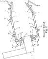
- FIG. 2 a simplified axial sectional view of a gas turbine combustor with burner seal.
- Fig. 3 is a schematic sectional view, analog Fig. 2 Showing the burner seal.
- combustion chamber comprises a combustion chamber wall 1 with a top plate 2, which is protected by a heat shield 3 against the combustion chamber.
- a heat shield 3 against the combustion chamber.
- shingles 7 are arranged, which by means of bolts 10 and nuts 11 are bolted to the combustion chamber wall 1 and shield them from the combustion chamber.
- annular combustion chamber At the in Fig. 2 shown construction is an annular combustion chamber. It should be understood that this has an outer and an inner combustion chamber wall based on a radial center direction based on an engine center axis. This is for the sake of simplicity in Fig. 2 not explained in detail.
- the Fig. 2 further shows that the heat shield 3 is provided with cooling holes 14 through which cooling air flowing through cooling air holes 15 of the head plate 2 is used for cooling the heat shield 3.
- the heat shield 3 is as in Fig. 2 represented by means of bolts 10 and nuts 11 mounted on the top plate 2.
- Both the top plate 2 and the heat shield 3 have a recess in which a burner seal 6 is arranged.
- a burner seal 6 is introduced from the outside a fuel nozzle 5 shown only schematically. This is performed through a recess of the combustion chamber head 4 and positioned in the burner seal 6.
- the burner seal 6 is floatingly mounted between the head plate 2 and the heat shield 3. This allows movement of the fuel nozzle 5 relative to the combustion chamber and has the same purpose as the fuel nozzle 5 place so that no leakage between the fuel nozzle 5 and the top plate 2 and the heat shield 3 is formed.
- the Fig. 2 shows by the dashed lines in a simplified representation of the flow path of cooling air, which flows from the interior of the combustion chamber head 4 along the burner seal 6.
- the Fig. 3 shows the structure of the burner seal 6 according to the prior art in a simplified representation.
- the burner seal 6 comprises an inlet lip 18, to which in the axial direction (with respect to a central axis of the fuel nozzle 5) a diameter region with a larger inner diameter adjoins. This results in flow paths to in the Fig. 3 dashed shown cooling air flow and dissipate through cooling holes 9.
- the cooling holes 9 are arranged in the axial direction in front of a sealing surface 16.
- the sealing surface 16 bears sealingly against the fuel nozzle 5.
- a funnel 17 (funnel-shaped lip) is provided, which extends into the interior of the combustion chamber, as in Fig. 2 is shown.
- the burner seal 6 comprises an annular web 19, which serves for fastening and mounting of the burner seal 6 on the top plate 2 and the heat shield 3, respectively.
- the burner seal 6 is designed to be aerodynamically low upstream of the combustion chamber head 4 in order to control the inflow of the cooling air (see FIG. Fig. 3 ) to improve.
- the inlet lip 18, which conducts the flow from the combustion chamber head 4 low to the fuel nozzle 5 is used.
- the burner seal 6 has a funnel-shaped shape (funnel 17) in order to allow the flow from the fuel nozzle to open as far as possible radially.
- the hopper 17, which protrudes into the combustion chamber, must be sufficiently cooled to prevent burning.
- the cooling air is passed through the discrete cooling air holes 9.
- the cooling holes 9 serve to direct the flow from the combustion chamber head 4 radially outwardly from the inside of the burner seal 6 to the outside thereof and to flow around the funnel 17 from its rear side.
- the funnel 17 is cooled by the cooling air on its rear side before the cooling air flows between the heat shield 3 and the burner seal 6 into the combustion chamber.
- the funnel 17 of the burner seal 6 is cooled only on its rear side, which faces away from the combustion chamber. This can not be sufficiently ensured that the hopper 17 and thus the burner seal 6 overheats and wears, for example by burning. Thus, the burner seal 6 must be replaced when worn. This requires extensive assembly work that is costly and time consuming.
- Another disadvantage is that the air flowing out of the burner seal 6 air can not be used to control emissions of the combustion chamber, since the air flow is very vague and untargeted.
- the invention is based on the object to provide a burner seal of the type mentioned, which avoids the disadvantages of the prior art with a simple structure and simple, cost-effective manufacturability and allows both improved cooling and improved air flow.
- Another object of the invention is to provide a method of making an improved burner gasket.
- cooling channels are each formed in the base body in the region of the sealing surface and the funnel and each exit from the funnel in an end region of the funnel in an exit hole.
- the object is achieved in that the burner seal is produced by means of an additive manufacturing method, for example by means of a laser deposition method (DLD) or a similar method.
- DLD laser deposition method
- the cooling channels according to the invention which are simple and inexpensive to implement by an additive method.
- Such cooling channels can not be produced by a conventional drilling method, since their course and their geometry are very complex.
- the cooling channels are designed so that they, viewed in the flow direction, relative to the fuel nozzle, are arranged in the interior of the burner seal in the region of the sealing surface and exit in the end region of the funnel.
- the cooling air flowing through the cooling channels can flow out at the end region of the funnel and effectively cool the entire funnel.
- the air flow can preferably be designed so that the exiting air is introduced to reduce emissions in the interior of the combustion chamber.
- the outlet hole opens in an outermost end region of the funnel. This can ensure that the cooling channel is passed through the entire funnel and exits at the substantially radially outwardly directed tip of the funnel. Thus, burnup of the funnel tip during operation can be avoided in a simple and cost-effective manner.
- the cooling passage extends completely through the funnel, the side of the funnel which is in the direction of flow to the combustion chamber as well as the side of the funnel facing away from the combustion chamber can be effectively cooled to the top of the funnel.
- a further improved effective cooling can be achieved if a center line of the exit hole of the cooling channel at the end region of the funnel at an angle of 70 to 90 ° to a centerline of the funnel lies.
- the center line of the outlet hole is in a range of 70 ° to 80 ° and is more preferably 75 °.
- inclination of the center line exiting cooling air can be aerodynamically mixed into the main flow of the combustion chamber.
- the cooling channel in each case has an inlet hole, which is arranged in a region of the larger inner diameter of the base body of the burner seal. It is particularly advantageous if the inlet hole is positioned on an upstream side of the sealing area. In this way, the cooling air can flow through the area with the larger inner diameter in the burner seal and be introduced in an optimal manner in the cooling channels.
- the cooling channel may be formed according to the invention in different ways. It may extend rectilinearly at an angle to the central axis of the burner seal or curved or spiral.
- the cooling channel can also be composed of a plurality of straight sections or different curved or curved sections.
- various variants result in order to ensure optimum cooling of the burner seal, in particular of the sealing area and of the funnel.
- the cross section of the inlet hole and / or the outlet hole in such a way that an optimized flow occurs.
- the holes may be circular, elliptical, diamond-shaped or teardrop-shaped.
- the cooling channels in terms of their cross-sectional shape between the inlet hole and the outlet hole variable form, for example, with an elliptical inlet hole and a round outlet hole.
- the cross-sectional profile of the respective cooling channel can also be made constant between the inlet hole and the outlet hole.
- the cross section of the cooling channel can also be formed so that the inlet hole is the smallest area in terms of its cross section and the cooling channel widens in cross section. He can form a cavity and rejuvenate to the exit hole.
- the burner seal preferably has a number of cooling holes between ten and forty.
- the narrowest hole diameter (entrance hole or exit hole) is, for example, 0.5 mm to 1 mm in a circular cross section and / or has an area of 0.8 mm 2 to 3 mm 2 .
- the measures according to the invention improve the cooling of the burner seal, resulting in less wear and lower maintenance costs.
- the air guide according to the invention results in improved emission control. As a result, in particular soot emissions can be reduced.
- the burner seal can be produced with very complex geometries of the cooling channels and their inlet and outlet holes. This is not possible with other manufacturing processes.
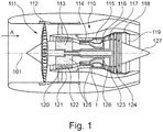
- the gas turbine engine 110 is a generalized example of a turbomachine, in which the invention can be applied.
- the engine 110 is formed in a conventional manner and comprises in succession an air inlet 111, a fan 112 circulating in a housing, a medium pressure compressor 113, a high pressure compressor 114, a combustion chamber 115, a high pressure turbine 116, a medium pressure turbine 117 and a low pressure turbine 118 and a Exhaust nozzle 119, which are all arranged around a central engine center axis 101.
- the intermediate pressure compressor 113 and the high pressure compressor 114 each include a plurality of stages, each of which includes a circumferentially extending array of fixed stationary vanes 120, commonly referred to as stator vanes, that radially inwardly from the core engine housing 121 into an annular flow passage through the compressors 113, 114 protrude.
- the compressors further include an array of compressor blades 122 projecting radially outwardly from a rotatable drum or disk 125 coupled to hubs 126 of high pressure turbine 116 and mid pressure turbine 117, respectively.
- the turbine sections 116, 117, 118 have similar stages, comprising an array of fixed vanes 123 projecting radially inward from the housing 121 into the annular flow passage through the turbines 116, 117, 118, and a downstream array of turbine blades 124, projecting outwardly from a rotatable hub 126.
- the compressor drum or compressor disk 125 and the vanes 122 disposed thereon and the turbine rotor hub 126 and turbine blades 124 disposed thereon rotate about the engine centerline 101 during operation.
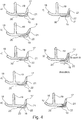
- the Fig. 4 shows different embodiments of the invention the burner seal 6 in an analog representation Fig. 3 , It can be seen in particular that adjacent to the region of larger inner diameter through which flows the cooling air (s. Fig. 3 ) In the axial direction in front of the sealing surface 16, an inlet hole 20 of a cooling channel 22 is arranged. The outflow of air from the cooling channel 22 takes place through an outlet hole 21.
- Fig. 4 show that the outlet hole 21 is positioned in each case on the combustion chamber side facing the funnel 17. As a result, the cooling air exits on the hot side of the funnel 17 and can hang as a cooling air film on the surface of the funnel.
- the cooling channel 22 can be dimensioned in different ways and formed in terms of its geometry.
- the cooling channel 22 is arcuately curved
- the Fig. 4b shows an s-shaped curvature, similar to the embodiment according to FIG Fig. 4c
- the outlet hole 21 is provided with an enlarged cross-section.
- the Fig. 4e shows a cross section of the cooling channel 22, which has a cavity 23 in its central region.
- the outlet hole 21 is positioned at a radially outer region of the funnel 17.
- the Fig. 4g shows a stepped, composed of rectilinear components cross-sectional shape of the cooling channel 22, while Fig. 4h shows an embodiment in which the cooling channel 22 is formed helically in order to optimize the cooling of the burner seal 6 and the funnel 17.
- the Fig. 4g shows views A and B, which in the FIGS. 5 and 6 are based on.
- the Fig. 5a shows each round entry holes 20 to which rectilinear ( Fig. 5a ), inclined ( Fig. 5b ), arcuate ( Fig. 5c ), coiled ( Fig. 5d ), diffuser-like extended ( Fig. 5e ) or provided with a cavity 23 ( Fig. 5f ) Connect courses of the cooling channels 22.
- the Fig. 6 shows in view A and view B possible embodiments of the entry holes 20 and the exit holes 21. These can be circular ( Fig. 6a ), oval ( Fig. 6b and 6c ) or diamond-shaped ( Fig. 6d ) be configured.
- Fig. 7 shows for clarity a perspective partial sectional view of the burner seal according to the invention, from which in particular the arrangement of the inlet hole 20, the outlet hole 21 and the cooling channel 22 results.
- the 8 and 9 each show perspective views of different design variants, which differ in particular with regard to the design and dimensioning of the inlet hole 20 and the outlet hole 21.
- FIGS. 10 to 12 show various variants of a particularly preferred embodiment of the present invention.
- the sealing surface 16 is formed with a smaller inner diameter than the upstream in the flow direction region of the inflow side with the annular inlet lip 18th
- the inlet holes 20 are distributed around the circumference provided at the transition region between the inflow side and the sealing surface 16. Starting from the inlet hole 20, the cooling channel 22 extends in the hopper 17 to an outermost end portion 17a of the hopper 17 and exits from the outermost end portion 17a of an outlet hole 21 from.
- the outermost end portion 17a of the funnel 17 is, as in particular from Fig. 10 it can be seen, arcuate in section, in particular formed semicircular.
- the exit hole 21 lies in this arcuate, outermost end portion 17a.
- a central axis 24, which leads through a center of the outlet hole 21, at an angle ⁇ to a main axis 25 of the burner seal 6 is arranged.
- the angle ⁇ is 75 °. In this way, a particularly good air flow of the cooling air through the funnel 17 and at the outlet of the funnel can be achieved.
- the entire funnel 17 can be cooled both on its side directed towards the combustion chamber and on its side facing away from the combustion chamber.
- the cooling channel 22 is guided through the hopper 17 such that a wall thickness is equal to the side facing the combustion chamber and to the side facing away from the combustion chamber side. This allows a particularly good stability of the funnel.
- a diameter of the cooling channel 22 tapers.
- the cooling channel is formed as a nozzle.
- the cooling channel can cool the sealing region 16, at which the burner seal 6 makes contact with the fuel nozzle, as well as effectively cool the funnel 17 up to the end region 17a of the funnel.
- cooling channel 22 can be dimensioned in a variety of ways and formed with respect to its geometry.
- the cooling channel is arcuately curved, starting from the entry hole 20 first a rectilinear region is formed substantially parallel to the sealing surface 16 and after the arc again a substantially rectilinear region is provided to the outermost end portion 17a of the funnel.
- the exit hole 21 is provided at the outermost tip of the hopper 17.
- Fig. 11b shows an S-shaped curvature of the cooling channel 22, wherein the funnel 17 projects slightly further into the combustion chamber.
- Fig. 11c shows an embodiment similar to Fig. 11b , wherein the exit hole 21 is aligned at almost a 90 ° angle to the central axis 25 of the burner seal.
- Fig. 11d shows an embodiment in which a cross section of the cooling channel 22, starting from the inlet hole 20 to the outlet hole 21 continuously tapers.
- Fig. 11e shows a cooling channel 22, which has a cavity 23 in a central region.
- Fig. 11f shows a cooling channel 22, wherein a diameter of the inlet hole 20 is smaller than a diameter of the outlet hole 21.
- the cooling channel of Fig. 11f a diffuser effect.
- Fig. 11g shows a stepped, composed of rectilinear components cross-sectional shape of the cooling channel 22nd
- Fig. 11h shows a preferred embodiment in which the cooling channel 22 is formed helically to optimize the cooling of the burner seal 6 of the hopper 17, in particular at the end facing the combustion chamber of the burner seal 6.
- FIG. 11g schematically again views A and B are shown, wherein the geometric shape of the inlet holes 20 and the outlet holes 21 in accordance with the in FIGS. 5 and 6 designed examples is designed. In this case, any combination in different geometric shapes of the inlet holes 20 and the outlet holes 21 are possible.
- Fig. 12 shows a further particularly preferred embodiment of the invention, which substantially the in Fig. 10 shown embodiment corresponds.
- the outermost end portion 17a formed rectilinear.
- the outermost end portion 17a forms an area E, which is parallel to the central axis 25 of the burner seal 6.
- the angle ⁇ is exactly 90 ° in this embodiment.
- the combustor seal 6 of a gas turbine shown provides a significant improvement in the cooling of the burner seal, resulting in less wear and, in particular, lower maintenance costs, since the combustor seal 6 no longer needs to be changed as frequently as in the prior art.
- the possibility of complete cooling of the funnel results from the inventive solution of providing the outlet hole 21 at the end region 17a of the funnel 17. It can also be avoided that regions which are too hot on the funnel 17 occur both on the side facing the combustion chamber and on the side of the funnel which faces away from the combustion chamber.
Landscapes
- Engineering & Computer Science (AREA)
- Chemical & Material Sciences (AREA)
- Combustion & Propulsion (AREA)
- Mechanical Engineering (AREA)
- General Engineering & Computer Science (AREA)
- Turbine Rotor Nozzle Sealing (AREA)
Abstract
Description
- Die Erfindung bezieht sich auf eine Brennerdichtung einer Gasturbine sowie auf ein Verfahren zu deren Herstellung.
- Im Einzelnen bezieht sich die Erfindung auf eine Brennerdichtung mit einem im Wesentlichen rohrförmigen Grundkörper, welcher an einer Einströmseite eine ringförmige Einlauflippe und an seiner Abströmseite einen Trichter aufweist, wobei ein Innendurchmesser der Einströmseite größer ausgebildet ist als ein Innendurchmesser einer axial vor dem Trichter angeordneten Dichtfläche, wobei um den Umfang verteilt in dem Grundkörper Kühlkanäle ausgebildet sind.
- Eine Brennerdichtung der oben stehenden Art wird verwendet, um Treibstoffdüsen einer Brennkammer einer Gasturbine gegenüber einer Kopfplatte und/oder einem Hitzeschild der Brennkammer abzudichten. Dabei steht insbesondere der Trichter der Brennerdichtung in den Brennraum vor und ist den dort herrschenden hohen Temperaturen ausgesetzt. Infolgedessen ist es erforderlich, die Brennerdichtung und insbesondere den Trichter ausreichend zu kühlen. Bei einer nicht ausreichenden Kühlung besteht die Gefahr, dass der Trichter mit der an ihm ausgebildeten trichterförmigen Lippe abbrennt.
- Nachfolgend wird der der Erfindung zu Grunde liegende Stand der Technik anhand der
Fig. 2 und3 beschrieben. Dabei zeigt dieFig. 2 eine vereinfachte Axial-Schnittansicht einer Gasturbinenbrennkammer mit Brennerdichtung. InFig. 3 ist eine schematische Schnittansicht, analogFig. 2 , der Brennerdichtung gezeigt. - Die in
Fig. 2 dargestellte Brennkammer umfasst eine Brennkammerwand 1 mit einer Kopfplatte 2, welche mittels eines Hitzeschilds 3 gegen den Brennraum geschützt ist. An der Innenseite der Brennkammerwand 1 sind Schindeln 7 angeordnet, welche mittels Bolzen 10 und Muttern 11 mit der Brennkammerwand 1 verschraubt sind und diese gegenüber dem Brennraum abschirmen. - Bei der in
Fig. 2 gezeigten Konstruktion handelt es sich um eine Ringbrennkammer. Es versteht sich, dass diese, bezogen auf eine Radialrichtung basierend auf einer Triebwerksmittelachse eine äußere und eine innere Brennkammerwand aufweist. Dies wird aus Gründen der Vereinfachung inFig. 2 im Einzelnen nicht erläutert. - In der Brennkammerwand 1 sind Zumischlöcher 8 vorgesehen, welche auch die Schindeln 7 durchgreifen und zur Zufuhr von Mischluft dienen. Die Brennkammerwand ist mit Prallkühllöchern 12 versehen, die Schindeln 7 weisen Effusionskühllöcher 13 auf. All dies ist aus dem Stand der Technik bekannt, sodass auf eine detaillierte weitergehende Beschreibung verzichtet werden kann.
- Die
Fig. 2 zeigt weiterhin, dass das Hitzeschild 3 mit Kühllöchern 14 versehen ist, durch welche Kühlluft, welche durch Kühlluftlöcher 15 der Kopfplatte 2 strömt, zur Kühlung des Hitzeschilds 3 Verwendung findet. Das Hitzeschild 3 ist, wie inFig. 2 dargestellt, mittels Bolzen 10 und Muttern 11 an der Kopfplatte 2 gelagert. - Sowohl die Kopfplatte 2 als auch das Hitzeschild 3 weisen eine Ausnehmung auf, in welcher eine Brennerdichtung 6 angeordnet ist. Durch die Brennerdichtung 6 wird von außen eine nur schematisch dargestellte Treibstoffdüse 5 eingeführt. Diese wird durch eine Ausnehmung des Brennkammerkopfes 4 durchgeführt und in der Brennerdichtung 6 positioniert.
- Um die Treibstoffdüse 5 gegenüber der Brennkammer in geeigneter Weise zu lagern und abzudichten, befindet sich zwischen der Kopfplatte 2 und dem Hitzeschild 3 schwimmend gelagert die Brennerdichtung 6. Diese erlaubt eine Bewegung der Treibstoffdüse 5 relativ zu der Brennkammer und hat gleichzeitig den Zweck, die Treibstoffdüse 5 so zu platzieren, dass keine Leckage zwischen der Treibstoffdüse 5 und der Kopfplatte 2 beziehungsweise dem Hitzeschild 3 entsteht. Die
Fig. 2 zeigt durch die gestrichelten Linien in vereinfachter Darstellung den Strömungsweg von Kühlluft, welche aus dem Innenraum des Brennkammerkopfes 4 entlang der Brennerdichtung 6 strömt. - Die
Fig. 3 zeigt den Aufbau der Brennerdichtung 6 gemäß dem Stand der Technik in vereinfachter Darstellung. Die Brennerdichtung 6 umfasst eine Einlauflippe 18, an die sich in axialer Richtung (bezogen auf eine Mittelachse der Treibstoffdüse 5) ein Durchmesserbereich mit einem größeren Innendurchmesser anschließt. Hierdurch ergeben sich Strömungswege, um die inFig. 3 gestrichelt dargestellte Kühlluftströmung einzuleiten und durch Kühllöcher 9 abzuführen. Die Kühllöcher 9 sind in Axialrichtung vor einer Dichtfläche 16 angeordnet. Die Dichtfläche 16 liegt dichtend gegen die Treibstoffdüse 5 an. In Axialrichtung anschließend an die Dichtfläche 16 ist ein Trichter 17 (trichterförmige Lippe) vorgesehen, welcher sich in den Innenraum der Brennkammer erstreckt, so wie dies inFig. 2 dargestellt ist. Weiterhin umfasst die Brennerdichtung 6 einen Ringsteg 19, welcher zur Befestigung und Lagerung der Brennerdichtung 6 an der Kopfplatte 2 beziehungsweise dem Hitzeschild 3 dient. - Die Brennerdichtung 6 ist stromauf zum Brennkammerkopf 4 weisend aerodynamisch günstig ausgebildet, um die Einströmung der Kühlluft (s.
Fig. 3 ) zu verbessern. Hierzu dient die Einlauflippe 18, welche die Strömung aus dem Brennkammerkopf 4 günstig zur Treibstoffdüse 5 leitet. Auch stromab zum Brennraum weisend weist die Brennerdichtung 6 eine trichterförmige Formgebung (Trichter 17) auf, um der Strömung aus der Treibstoffdüse die Möglichkeit zu geben, sich radial möglichst weit zu öffnen. Der Trichter 17, welcher in den Brennraum vorsteht, muss ausreichend gekühlt werden, um ein Abbrennen zu verhindern. Hierzu wird gemäß dem Stand der Technik die Kühlluft durch die diskreten Kühlluftlöcher 9 geleitet. Die Kühllöcher 9 dienen dazu, die Strömung aus dem Brennkammerkopf 4 radial nach außen von der Innenseite der Brennerdichtung 6 zu deren Außenseite zu leiten und den Trichter 17 von seiner Rückseite aus zu umströmen. Hierdurch wird der Trichter 17 durch die Kühlluft an seiner Rückseite gekühlt, bevor die Kühlluft zwischen Hitzeschild 3 und Brennerdichtung 6 in den Brennraum strömt. - Es erweist sich als nachteilig, dass der Trichter 17 der Brennerdichtung 6 nur an seiner Rückseite, welche dem Brennraum abgewandt ist, gekühlt wird. Hierdurch kann nicht ausreichend sichergestellt werden, dass der Trichter 17 und damit die Brennerdichtung 6 überhitzt und verschleißt, beispielsweise durch Abbrand. Somit muss die Brennerdichtung 6 bei Verschleiß ausgetauscht werden. Dies erfordert umfangreiche Montagearbeiten, die kostenintensiv und zeitaufwendig sind. Ein weiterer Nachteil besteht darin, dass die aus der Brennerdichtung 6 ausströmende Luft nicht zur Kontrolle von Emissionen der Brennkammer genutzt werden kann, da die Luftführung sehr unbestimmt und ungezielt erfolgt.
- Der Erfindung liegt die Aufgabe zu Grunde, eine Brennerdichtung der eingangs genannten Art zu schaffen, welche bei einfachem Aufbau und einfacher, kostengünstiger Herstellbarkeit die Nachteile des Standes der Technik vermeidet und sowohl eine verbesserte Kühlung als auch eine verbesserte Luftführung ermöglicht. Eine weitere Aufgabe der Erfindung besteht darin, ein Verfahren zur Herstellung einer verbesserten Brennerdichtung zu schaffen.
- Erfindungsgemäß wird die Aufgabe durch die Merkmalskombinationen der nebengeordneten Ansprüche gelöst. Die Unteransprüche zeigen weitere vorteilhafte Ausgestaltungen der Erfindung.
- Erfindungsgemäß ist somit vorgesehen, dass die Kühlkanäle jeweils in dem Grundkörper im Bereich der Dichtfläche und des Trichter ausgebildet sind und jeweils in einem Endbereich des Trichters in einem Austrittsloch aus dem Trichter austreten.
- Hinsichtlich des Verfahrens wird die Aufgabe dadurch gelöst, dass die Brennerdichtung mittels eines additiven Herstellverfahrens hergestellt wird, beispielsweise mittels eines Laserauftragsverfahrens (DLD) oder eines ähnlichen Verfahrens.
- Durch die erfindungsgemäße Lösung ist die Möglichkeit geschaffen worden, insbesondere den Bereich der Dichtfläche und des Trichters der Brennerdichtung sowie den im Wesentlichen radial nach außen gerichteten Bereich des Trichters bis zum Endbereich des Trichters intern zu kühlen. Hierzu dienen die erfindungsgemäßen Kühlkanäle, welche durch ein additives Verfahren einfach und kostengünstig realisierbar sind. Derartige Kühlkanäle können nicht durch ein herkömmliches Bohrverfahren erzeugt werden, da ihr Verlauf und ihre Geometrie sehr komplex sind. Die Kühlkanäle sind dabei so ausgebildet, dass sie, in Strömungsrichtung, bezogen auf die Treibstoffdüse, gesehen, im Inneren der Brennerdichtung im Bereich der Dichtfläche angeordnet sind und im Endbereich des Trichters austreten. Hierdurch kann die durch die Kühlkanäle strömende Kühlluft am Endbereich des Trichters ausströmen und in effektiver Weise den gesamten Trichter kühlen. Weiterhin kann die Luftströmung bevorzugt so gestaltet werden, dass die austretende Luft zur Reduzierung von Emissionen in den Innenraum der Brennkammer eingeleitet wird.
- Besonders bevorzugt mündet das Austrittsloch in einem äußersten Endbereich des Trichters. Dadurch kann sichergestellt werden, dass der Kühlkanal durch den kompletten Trichter hindurchgeführt wird und an der im Wesentlichen radial nach außen gerichteten Spitze des Trichters austritt. Somit kann auf einfache und kostengünstige Weise ein Abbrand der Trichterspitze im Betrieb vermieden werden. Da somit der Kühlkanal vollständig durch den Trichter verläuft, können die in Strömungsrichtung zur Brennkammer liegende Seite des Trichters als auch die von der Brennkammer abgewandte Seite des Trichters effektiv bis zur Spitze des Trichters gekühlt werden.
- Eine weiter verbesserte effektive Kühlung kann erreicht werden, wenn eine Mittellinie des Austrittslochs des Kühlkanals am Endbereich des Trichters in einem Winkel von 70 bis 90° zu einer Mittellinie des Trichters liegt. Besonders bevorzugt liegt die Mittellinie des Austrittslochs dabei in einem Bereich von 70° bis 80° und beträgt weiter bevorzugt 75°. Insbesondere im Bereich zwischen 70 und 80° Neigung der Mittellinie kann austretende Kühlluft strömungsgünstig in die Hauptströmung der Brennkammer zugemischt werden.
- Um die Luftströmung durch die Kühlkanäle zu optimieren, ist es besonders vorteilhaft, wenn der Kühlkanal jeweils ein Eintrittsloch aufweist, welches in einem Bereich des größeren Innendurchmessers des Grundkörpers der Brennerdichtung angeordnet ist. Besonders vorteilhaft ist es, wenn das Eintrittsloch an einer stromauf liegenden Seite des Dichtbereichs positioniert ist. Hierdurch kann die Kühlluft durch den Bereich mit dem größeren Innendurchmesser in die Brennerdichtung einströmen und in optimaler Weise in die Kühlkanäle eingeleitet werden.
- Der Kühlkanal kann erfindungsgemäß in unterschiedlicher Weise ausgebildet sein. Er kann sich geradlinig, mit einem Winkel zur Mittelachse der Brennerdichtung oder gekrümmt oder spiralförmig erstrecken. Der Kühlkanal kann auch aus mehreren geradlinigen Abschnitten oder unterschiedlichen gebogenen oder gekrümmten Abschnitten zusammengesetzt sein. Es ergeben sich erfindungsgemäß somit verschiedenste Varianten, um eine optimale Kühlung der Brennerdichtung, insbesondere des Dichtbereichs und des Trichters sicherzustellen.
- Weiterhin kann es erfindungsgemäß vorteilhaft sein, den Querschnitt des Eintrittslochs und/oder des Austrittslochs so auszugestalten, dass eine optimierte Durchströmung erfolgt. Die Löcher können kreisförmig, elliptisch, rautenförmig oder tropfenförmig ausgebildet sein.
- Weiterhin kann in vorteilhafter Weiterbildung der Erfindung vorgesehen sein, die Kühlkanäle hinsichtlich ihrer Querschnittsform zwischen dem Eintrittsloch und dem Austrittsloch variabel auszubilden, beispielsweise mit einem elliptischen Eintrittsloch und einem runden Austrittsloch. Der Querschnittsverlauf des jeweiligen Kühlkanals kann zwischen dem Eintrittsloch und dem Austrittsloch auch konstant ausgestaltet sein. Es ist jedoch auch möglich, den Kühlkanal in Richtung des Austrittsloches aufzuweiten, sodass das Eintrittsloch einen engsten Querschnitt bildet und der Kühlkanal als Diffusor wirkt. Es ist alternativ auch möglich, den Kühlkanal düsenartig auszugestalten und somit das Austrittsloch mit einer geringeren Querschnittsfläche auszugestalten, als das Eintrittsloch. Der Querschnitt des Kühlkanals kann auch so ausgebildet sein, dass das Eintrittsloch hinsichtlich seines Querschnitts den kleinsten Bereich darstellt und sich der Kühlkanal im Querschnitt aufweitet. Er kann dabei eine Kavität bilden und sich zum Austrittsloch hin wiederum verjüngen.
- Die Brennerdichtung weist bevorzugterweise eine Anzahl von Kühllöchern zwischen zehn bis vierzig auf. Der engste Lochdurchmesser (Eintrittsloch oder Austrittsloch) beträgt beispielsweise bei einem kreisförmigen Querschnitt 0,5 mm bis 1 mm und/oder hat eine Fläche von 0,8 mm2 bis 3 mm2.
- Durch die erfindungsgemäßen Maßnahmen verbessert sich die Kühlung der Brennerdichtung, sodass sich ein geringerer Verschleiß und geringere Wartungskosten ergeben. Zusätzlich resultiert die erfindungsgemäße Luftführung in einer verbesserten Emissionskontrolle. Hierdurch können insbesondere Ruß-Emissionen reduziert werden.
- Mittels des erfindungsgemäßen Herstellungsverfahrens kann die Brennerdichtung mit sehr komplexen Geometrien der Kühlkanäle sowie deren Eintritts- und Austrittslöchern hergestellt werden. Dies ist mit anderen Herstellungsverfahren nicht möglich.
- Im Folgenden wird die Erfindung anhand von Ausführungsbeispielen in Verbindung mit der Zeichnung beschrieben. Dabei zeigt:
- Fig. 1
- ein Gasturbinentriebwerk zur Verwendung der erfindungsgemäßen Gasturbinenbrennkammer,
- Fig. 2
- eine vereinfachte Axialschnittansicht einer Gasturbinenbrennkammer gemäß dem Stand der Technik,
- Fig. 3
- eine vergrößerte Detailansicht der in
Fig. 2 gezeigten Brennerdichtung, - Fig. 4
- Schnittansichten unterschiedlicher Ausführungsbeispiele der Brennerdichtung und der Kühlkanäle in analoger Darstellung zu
Fig. 3 , - Fig. 5
- unterschiedliche Ausgestaltungsvarianten in Ansicht A gemäß
Fig. 4 , - Fig. 6
- unterschiedliche Ausgestaltungsvarianten in Ansicht A oder B gemäß
Fig. 4 , - Fig. 7
- eine Teilschnittansicht eines erfindungsgemäßen Ausführungsbeispiels analog
Fig. 4 , - Fig. 8 und 9
- perspektivische Ansichten unterschiedlicher Ausführungsbeispiele der Brennerdichtung,
- Fig. 10
- eine Schnittansicht einer Brennerdichtung gemäß einem besonders bevorzugten Ausführungsbeispiels der Erfindung,
- Fig. 11a-11
- h unterschiedliche Ausführungsbeispiele der Brennerdichtung mit alternativen Ausgestaltungen der Kühlkanäle gemäß dem besonders bevorzugtem Ausführungsbeispiel von
Fig. 10 und - Fig. 12
- eine Teilschnittansicht einer Brennerdichtung gemäß einem weiteren bevorzugten Ausführungsbeispiel der Erfindung.
- Das Gasturbinentriebwerk 110 gemäß
Fig. 1 ist ein allgemein dargestelltes Beispiel einer Turbomaschine, bei der die Erfindung Anwendung finden kann. Das Triebwerk 110 ist in herkömmlicher Weise ausgebildet und umfasst in Strömungsrichtung hintereinander einen Lufteinlass 111, einen in einem Gehäuse umlaufenden Fan 112, einen Mitteldruckkompressor 113, einen Hochdruckkompressor 114, eine Brennkammer 115, eine Hochdruckturbine 116, eine Mitteldruckturbine 117 und eine Niederdruckturbine 118 sowie eine Abgasdüse 119, die sämtlich um eine zentrale Triebwerksmittelachse 101 angeordnet sind. - Der Mitteldruckkompressor 113 und der Hochdruckkompressor 114 umfassen jeweils mehrere Stufen, von denen jede eine in Umfangsrichtung verlaufende Anordnung fester stationärer Leitschaufeln 120 aufweist, die allgemein als Statorschaufeln bezeichnet werden und die radial nach innen vom Kerntriebwerksgehäuse 121 in einen ringförmigen Strömungskanal durch die Kompressoren 113, 114 vorstehen. Die Kompressoren weisen weiter eine Anordnung von Kompressorlaufschaufeln 122 auf, die radial nach außen von einer drehbaren Trommel oder Scheibe 125 vorstehen, die mit Naben 126 der Hochdruckturbine 116 beziehungsweise der Mitteldruckturbine 117 gekoppelt sind.
- Die Turbinenabschnitte 116, 117, 118 weisen ähnliche Stufen auf, umfassend eine Anordnung von festen Leitschaufeln 123, die radial nach innen vom Gehäuse 121 in den ringförmigen Strömungskanal durch die Turbinen 116, 117, 118 vorstehen, und eine nachfolgende Anordnung von Turbinenschaufeln 124, die nach außen von einer drehbaren Nabe 126 vorstehen. Die Kompressortrommel oder Kompressorscheibe 125 und die darauf angeordneten Schaufeln 122 sowie die Turbinenrotornabe 126 und die darauf angeordneten Turbinenlaufschaufeln 124 drehen sich im Betrieb um die Triebwerksmittelachse 101.
- Die
Fig. 4 zeigt unterschiedliche erfindungsgemäße Ausführungsbeispiele der Brennerdichtung 6 in analoger Darstellung zuFig. 3 . Dabei ist insbesondere ersichtlich, dass angrenzend an den Bereich größeren Innendurchmessers, durch welchen die Kühlluft einströmt (s.Fig. 3 ) in Axialrichtung vor der Dichtfläche 16 ein Eintrittsloch 20 eines Kühlkanals 22 angeordnet ist. Die Ausströmung der Luft aus dem Kühlkanal 22 erfolgt durch ein Austrittsloch 21. - Die unterschiedlichen Ausgestaltungsvarianten der
Fig. 4 zeigen, dass das Austrittsloch 21 jeweils an der dem Brennraum zugewandten Seite des Trichters 17 positioniert ist. Hierdurch tritt die Kühlluft an der heißen Seite des Trichters 17 aus und kann sich als Kühlluftfilm auf die Oberfläche des Trichters auflegen. - Die Ausführungsbeispiele der
Fig. 4 zeigen, dass der Kühlkanal 22 in unterschiedlicher Weise dimensioniert und hinsichtlich seiner Geometrie ausgebildet sein kann. GemäßFig. 4a ist der Kühlkanal 22 bogenförmig gekrümmt, dieFig. 4b zeigt eine s-förmige Krümmung, ähnlich der Ausgestaltung gemäßFig. 4c . GemäßFig. 4d ist das Austrittsloch 21 mit einem vergrößerten Querschnitt versehen. DieFig. 4e zeigt einen Querschnitt des Kühlkanals 22, welcher in seinem mittleren Bereich eine Kavität 23 aufweist. GemäßFig. 4f ist das Austrittsloch 21 an einem radial außen liegenden Bereich des Trichters 17 positioniert. DieFig. 4g zeigt eine gestufte, aus geradlinigen Komponenten zusammengesetzte Querschnittsform des Kühlkanals 22, währendFig. 4h ein Ausführungsbeispiel zeigt, bei welchem der Kühlkanal 22 wendelartig ausgebildet ist, um die Kühlung der Brennerdichtung 6 beziehungsweise des Trichters 17 zu optimieren. - Die
Fig. 4g zeigt Ansichten A und B, welche in denFig. 5 und 6 zu Grunde gelegt sind. DieFig. 5a zeigt jeweils runde Eintrittslöcher 20, an welche sich geradlinige (Fig. 5a ), schräg gestellte (Fig. 5b ), bogenförmige (Fig. 5c ), gewendelte (Fig. 5d ), diffusorartig erweiterte (Fig. 5e ) oder mit einer Kavität 23 versehene (Fig. 5f ) Verläufe der Kühlkanäle 22 anschließen. - Die
Fig. 6 zeigt in Ansicht A beziehungsweise Ansicht B mögliche Ausgestaltungen der Eintrittslöcher 20 und der Austrittslöcher 21. Diese können kreisrund (Fig. 6a ), oval (Fig. 6b und 6c ) oder rautenförmig (Fig. 6d ) ausgestaltet sein. - Die
Fig. 7 zeigt zur Verdeutlichung eine perspektivische Teil-Schnittansicht der erfindungsgemäßen Brennerdichtung, aus welcher sich insbesondere die Anordnung des Eintrittslochs 20, des Austrittslochs 21 sowie des Kühlkanals 22 ergibt. - Die
Fig. 8 und 9 zeigen jeweils perspektivische Darstellungen unterschiedlicher Ausgestaltungsvarianten, welche sich insbesondere hinsichtlich der Ausgestaltung und Dimensionierung des Eintrittslochs 20 und des Austrittslochs 21 unterscheiden. - Die
Figuren 10 bis 12 zeigen verschiedene Varianten einer besonders bevorzugten Ausgestaltung der vorliegenden Erfindung. - Wie in
Fig. 10 gezeigt, dichtet die Brennerdichtung 6 an der Treibstoffdüse 5 mit der Dichtfläche 16 ab. Die Dichtfläche 16 ist mit einem kleineren Innendurchmesser ausgebildet als der in durch Strömungsrichtung davorliegende Bereich der Einströmseite mit der ringförmigen Einlauflippe 18. - Die Eintrittslöcher 20 sind dabei um den Umfang verteilt am Übergangsbereich zwischen der Einströmseite und der Dichtfläche 16 vorgesehen. Ausgehend vom Eintrittsloch 20 verläuft der Kühlkanal 22 im Trichter 17 bis zu einem äußersten Endbereich 17a des Trichters 17 und tritt aus dem äußersten Endbereich 17a aus einem Austrittsloch 21 aus.
- Der äußerste Endbereich 17a des Trichters 17 ist, wie insbesondere aus
Fig. 10 ersichtlich ist, im Schnitt bogenförmig, insbesondere halbkreisförmig ausgebildet. Das Austrittsloch 21 liegt dabei in diesem bogenförmigen, äußersten Endbereich 17a. Wie ausFig. 10 ersichtlich ist, ist eine Mittelachse 24, welche durch einen Mittelpunkt des Austrittslochs 21 führt, in einem Winkel α zu einer Hauptachse 25 der Brennerdichtung 6 angeordnet. In dem inFig. 10 gezeigten Ausführungsbeispiel beträgt der Winkel α dabei 75°. Hierdurch kann eine besonders gute Luftführung der Kühlluft durch den Trichter 17 sowie beim Austritt des Trichters erreicht werden. - Insbesondere kann der gesamte Trichter 17 sowohl an seiner zur Brennkammer gerichteten Seite als auch an seiner von der Brennkammer abgewandten Seite gekühlt werden. Hierbei ist der Kühlkanal 22 durch den Trichter 17 derart geführt, dass eine Wandstärke zu der zur Brennkammer gerichteten Seite als auch zu der von der Brennkammer abgewandten Seite gleich ist. Hierdurch wird eine besonders gute Stabilität des Trichters ermöglicht. In Strömungsrichtung verjüngt sich ein Durchmesser des Kühlkanals 22. Somit ist der Kühlkanal als Düse ausgebildet.
- Somit kann der Kühlkanal einerseits den Dichtbereich 16 kühlen, an welchem die Brennerdichtung 6 Kontakt mit der Treibstoffdüse hat, als auch den Trichter 17 bis zum Endbereich 17a des Trichters effektiv kühlen.
-
Fig. 11a bis 11h zeigen verschiedene Varianten für die Formgebung des Trichters. Hierbei wird deutlich, dass der Kühlkanal 22 in unterschiedlichster Weise dimensioniert und hinsichtlich seiner Geometrie ausgebildet sein kann. - In
Fig. 11a ist der Kühlkanal bogenförmig gekrümmt, wobei ausgehend vom Eintrittsloch 20 zuerst ein geradliniger Bereich im Wesentlichen parallel zur Dichtfläche 16 ausgebildet ist und nach dem Bogen ebenfalls wiederum ein im Wesentlichen geradliniger Bereich bis zum äußersten Endbereich 17a des Trichters vorgesehen ist. Das Austrittsloch 21 ist an der äußersten Spitze des Trichters 17 vorgesehen. -
Fig. 11b zeigt eine s-förmige Krümmung des Kühlkanals 22, wobei der Trichter 17 etwas weiter in den Brennraum hineinragt. -
Fig. 11c zeigt eine Ausgestaltung ähnlich zuFig. 11b , wobei das Austrittsloch 21 fast in einem 90°-Winkel zur Mittelachse 25 der Brennerdichtung ausgerichtet ist. -
Fig. 11d zeigt eine Ausführungsform, bei der sich ein Querschnitt des Kühlkanals 22 ausgehend vom Eintrittsloch 20 bis zum Austrittsloch 21 kontinuierlich verjüngt. -
Fig. 11e zeigt einen Kühlkanal 22, welcher in einem mittleren Bereich eine Kavität 23 aufweist. Dadurch kann eine verbesserte Kühlung an der Dichtfläche 16 erreicht werden. -
Fig. 11f zeigt einen Kühlkanal 22, bei dem ein Durchmesser des Eintrittslochs 20 kleiner ist als ein Durchmesser des Austrittslochs 21. Somit weist der Kühlkanal vonFig. 11f eine Diffusorwirkung auf. -
Fig. 11g zeigt eine gestufte, aus geradlinigen Komponenten zusammengesetzte Querschnittsform des Kühlkanals 22. -
Fig. 11h zeigt eine bevorzugte Ausführungsform, bei der der Kühlkanal 22 wendelartig ausgebildet ist, um die Kühlung der Brennerdichtung 6 des Trichters 17, insbesondere am zum Brennraum gerichteten Ende der Brennerdichtung 6, zu optimieren. - In
Fig. 11g sind schematisch nochmals die Ansichten A und B dargestellt, wobei die geometrische Form der Eintrittslöcher 20 und der Austrittslöcher 21 gemäß den inFig. 5 und 6 gezeigten Beispielen gestaltet ist. Hierbei sind auch beliebige Kombination in unterschiedlichen geometrischen Formen der Eintrittslöcher 20 bzw. der Austrittslöcher 21 möglich. -
Fig. 12 zeigt eine weitere besonders bevorzugte Ausgestaltung der Erfindung, welche im Wesentlichen der inFig. 10 gezeigten Ausgestaltung entspricht. Im Unterschied dazu ist bei der inFig. 12 gezeigten bevorzugten Ausführungsform der äußerste Endbereich 17a geradlinig ausgebildet. Dabei bildet der äußerste Endbereich 17a eine Fläche E, welche parallel zur Mittelachse 25 der Brennerdichtung 6 ist. Der Winkel α beträgt in diesem Ausführungsbeispiel genau 90°. - Somit stellt die gezeigte Brennerdichtung 6 einer Gasturbine eine deutliche Verbesserung einer Kühllung der Brennerdichtung bereit, so dass sich ein geringerer Verschleiß und insbesondere auch geringere Wartungskosten ergeben, da die Brennerdichtung 6 nicht mehr so häufig wie im Stand der Technik ausgewechselt werden muss. Zusätzlich ergibt sich durch die erfindungsgemäße Lösung des Vorsehens des Austrittsloch 21 am Endbereich 17a des Trichters 17 die Möglichkeit, einer vollständigen Kühlung des Trichters. Auch kann vermieden werden, dass am Trichter 17 zu heiße Bereiche sowohl an der Brennkammer gerichteten Seite als auch von der Brennkammer abgewandten Seite des Trichters auftreten.
- Alternativ kann die vorliegende Erfindung auch durch die nachfolgenden Sätze beschrieben werden:
- 1. Brennerdichtung einer Gasturbine mit einem im Wesentlichen rohrförmigen Grundkörper, welcher an einer Einströmseite eine ringförmige Einlauflippe (18) und an seiner Abströmseite einen Trichter (17) aufweist, wobei ein Innendurchmesser der Einströmseite größer ausgebildet ist, als ein Innendurchmesser einer axial vor dem Trichter angeordneten Dichtfläche (16), wobei um den Umfang verteilt in dem Grundkörper Kühlkanäle (22) ausgebildet sind, dadurch gekennzeichnet, dass die Kühlkanäle (22) jeweils in dem Grundkörper im Bereich der Dichtfläche (16) und des Trichters (17) ausgebildet sind und jeweils in einem axial nach außen weisenden Bereich des Trichters (17) in einem Austrittsloch (21) münden.
- 2. Brennerdichtung nach Satz 1, dadurch gekennzeichnet, dass die Kühlkanäle (22) jeweils ein Eintrittsloch (20) aufweisen, welches in einem Bereich des größeren Innendurchmessers des Grundkörpers angeordnet ist.
- 3. Brennerdichtung nach Satz 1 oder 2, dadurch gekennzeichnet, dass die Kühlkanäle (22) jeweils ein Eintrittsloch (20) aufweisen, welches in dem Dichtbereich (16) angeordnet ist.
- 4. Brennerdichtung nach einem der Sätze 1 bis 3, dadurch gekennzeichnet, dass das Austrittsloch (21) zur Ausbildung eines Kühlluftfilms auf der Außenseite des Trichters (17) ausgestaltet ist.
- 5. Brennerdichtung nach einem der Sätze 1 bis 4, dadurch gekennzeichnet, dass das Austrittsloch (21) zur Ausbildung eines Kühlluftstroms in radial nach außen weisender Richtung aus dem Trichter (17) ausgestaltet ist.
- 6. Brennerdichtung nach einem der Sätze 1 bis 5, dadurch gekennzeichnet, dass der Kühlkanal (22) mit einem kreisförmigen, elliptischen, rautenförmigen und/oder tropfenförmigen Querschnitt versehen ist.
- 7. Brennerdichtung nach einem der Sätze 1 bis 6, dadurch gekennzeichnet, dass der Querschnitt des Kühlkanals (22) über dessen Länge variabel ausgebildet ist.
- 8. Brennerdichtung nach einem der Sätze 1 bis 7, dadurch gekennzeichnet, dass der Kühlkanal (22) über seine Länge gekrümmt, gebogen und/oder geradlinig ausgebildet ist.
- 9. Brennerdichtung nach einem der Sätze 1 bis 8, dadurch gekennzeichnet, dass die Flächen des Eintrittslochs (20) und des Austrittslochs (21) jeweils gleich oder unterschiedlich bemessen sind.
- 10. Verfahren zur Herstellung einer Brennerdichtung (6) nach einem der Sätze 1 bis 9, wobei das Verfahren ein additives Verfahren ist.
-
- 1
- Brennkammerwand
- 2
- Kopfplatte
- 3
- Hitzeschild
- 4
- Brennkammerkopf
- 5
- Treibstoffdüse
- 6
- Brennerdichtung
- 7
- Schindel
- 8
- Zumischloch
- 9
- Kühlloch
- 10
- Bolzen
- 11
- Mutter
- 12
- Prallkühlloch
- 13
- Effusionskühlloch
- 14
- Kühlloch
- 15
- Kühlluftloch
- 16
- Dichtfläche
- 17
- Trichter
- 17a
- äußerster Endbereich des Trichters
- 18
- Einlauflippe
- 19
- Ringsteg
- 20
- Eintrittsloch
- 21
- Austrittsloch
- 22
- Kühlkanal
- 23
- Kavität
- 24
- Mittelachse
- 25
- Mittelachse der Brennerdichtung
- α
- Winkel zwischen Mittelachse 24 des Austrittslochs und Mittelachse 25 der Brennerdichtung
- E
- Fläche des äußersten Endbereichs 17a
- 101
- Triebwerksmittelachse
- 110
- Gasturbinentriebwerk / Kerntriebwerk
- 111
- Lufteinlass
- 112
- Fan
- 113
- Mitteldruckkompressor (Verdichter)
- 114
- Hochdruckkompressor
- 115
- Brennkammer
- 116
- Hochdruckturbine
- 117
- Mitteldruckturbine
- 118
- Niederdruckturbine
- 119
- Abgasdüse
- 120
- Leitschaufeln
- 121
- Kerntriebwerksgehäuse
- 122
- Kompressorlaufschaufeln
- 123
- Leitschaufeln
- 124
- Turbinenschaufeln
- 125
- Kompressortrommel oder -scheibe
- 126
- Turbinenrotornabe
- 127
- Auslasskonus
Claims (10)
- Brennerdichtung einer Gasturbine mit einem im Wesentlichen rohrförmigen Grundkörper, welcher an einer Einströmseite eine ringförmige Einlauflippe (18) und an seiner Abströmseite einen Trichter (17) aufweist, wobei ein Innendurchmesser der Einströmseite größer ausgebildet ist, als ein Innendurchmesser einer axial vor dem Trichter angeordneten Dichtfläche (16), wobei um den Umfang verteilt in dem Grundkörper Kühlkanäle (22) ausgebildet sind, wobei die Kühlkanäle (22) jeweils in dem Grundkörper im Bereich der Dichtfläche (16) und des Trichters (17) ausgebildet sind und jeweils in einem Endbereich (17a) des Trichters (17) in einem Austrittsloch (21) münden.
- Brennerdichtung nach Anspruch 1, wobei das Austrittsloch (21) in einem äußersten Endbereich (17a) des Trichters mündet.
- Brennerdichtung nach einem der vorherigen Ansprüche, wobei eine Mittelachse (24) des Austrittslochs (21) in einem Winkel (α) von 70° bis 90°, insbesondere 70° bis 80° und weiter insbesondere 75°, zur einer Mittelachse (25) der Brennerdichtung liegt.
- Brennerdichtung nach Anspruch 1, wobei die Kühlkanäle (22) jeweils ein Eintrittsloch (20) aufweisen, welches in einem Bereich des größeren Innendurchmessers des Grundkörpers angeordnet ist.
- Brennerdichtung nach Anspruch 1 oder 2, wobei die Kühlkanäle (22) jeweils ein Eintrittsloch (20) aufweisen, welches in dem Dichtbereich (16) angeordnet ist.
- Brennerdichtung nach einem der Ansprüche 1 bis 5, wobei der Kühlkanal (22) mit einem kreisförmigen, elliptischen, rautenförmigen und/oder tropfenförmigen Querschnitt versehen ist.
- Brennerdichtung nach einem der Ansprüche 1 bis 6, wobei der Querschnitt des Kühlkanals (22) über dessen Länge variabel ausgebildet ist.
- Brennerdichtung nach einem der Ansprüche 1 bis 7, wobei der Kühlkanal (22) über seine Länge gekrümmt, gebogen und/oder geradlinig ausgebildet ist.
- Brennerdichtung nach einem der Ansprüche 1 bis 8, wobei die Flächen des Eintrittslochs (20) und des Austrittslochs (21) jeweils gleich oder unterschiedlich bemessen sind.
- Verfahren zur Herstellung einer Brennerdichtung (6) nach einem der Ansprüche 1 bis 9, wobei das Verfahren ein additives Verfahren ist.
Priority Applications (1)
| Application Number | Priority Date | Filing Date | Title |
|---|---|---|---|
| EP17201073.8A EP3483503B1 (de) | 2017-11-10 | 2017-11-10 | Brennerdichtung einer gasturbine und verfahren zu deren herstellung |
Applications Claiming Priority (1)
| Application Number | Priority Date | Filing Date | Title |
|---|---|---|---|
| EP17201073.8A EP3483503B1 (de) | 2017-11-10 | 2017-11-10 | Brennerdichtung einer gasturbine und verfahren zu deren herstellung |
Publications (2)
| Publication Number | Publication Date |
|---|---|
| EP3483503A1 true EP3483503A1 (de) | 2019-05-15 |
| EP3483503B1 EP3483503B1 (de) | 2021-01-06 |
Family
ID=60320705
Family Applications (1)
| Application Number | Title | Priority Date | Filing Date |
|---|---|---|---|
| EP17201073.8A Active EP3483503B1 (de) | 2017-11-10 | 2017-11-10 | Brennerdichtung einer gasturbine und verfahren zu deren herstellung |
Country Status (1)
| Country | Link |
|---|---|
| EP (1) | EP3483503B1 (de) |
Cited By (1)
| Publication number | Priority date | Publication date | Assignee | Title |
|---|---|---|---|---|
| DE102024200444A1 (de) * | 2024-01-18 | 2025-07-24 | Rolls-Royce Deutschland Ltd & Co Kg | Düsenbaugruppe für eine Brennkammer eines Triebwerks und Brennerdichtung |
Citations (4)
| Publication number | Priority date | Publication date | Assignee | Title |
|---|---|---|---|---|
| DE19508111A1 (de) * | 1995-03-08 | 1996-09-12 | Bmw Rolls Royce Gmbh | Hitzeschild-Anordnung für eine Gasturbinen-Brennkammer |
| US20080236169A1 (en) * | 2007-03-30 | 2008-10-02 | Eduardo Hawie | Combustor floating collar with louver |
| US20140367494A1 (en) * | 2013-06-14 | 2014-12-18 | Delavan Inc | Additively manufactured nozzle tip for fuel injector |
| US20150260409A1 (en) * | 2014-03-11 | 2015-09-17 | Rolls-Royce Deutschland Ltd & Co Kg | Gas turbine combustion chamber and method for manufacturing the same |
-
2017
- 2017-11-10 EP EP17201073.8A patent/EP3483503B1/de active Active
Patent Citations (4)
| Publication number | Priority date | Publication date | Assignee | Title |
|---|---|---|---|---|
| DE19508111A1 (de) * | 1995-03-08 | 1996-09-12 | Bmw Rolls Royce Gmbh | Hitzeschild-Anordnung für eine Gasturbinen-Brennkammer |
| US20080236169A1 (en) * | 2007-03-30 | 2008-10-02 | Eduardo Hawie | Combustor floating collar with louver |
| US20140367494A1 (en) * | 2013-06-14 | 2014-12-18 | Delavan Inc | Additively manufactured nozzle tip for fuel injector |
| US20150260409A1 (en) * | 2014-03-11 | 2015-09-17 | Rolls-Royce Deutschland Ltd & Co Kg | Gas turbine combustion chamber and method for manufacturing the same |
Cited By (1)
| Publication number | Priority date | Publication date | Assignee | Title |
|---|---|---|---|---|
| DE102024200444A1 (de) * | 2024-01-18 | 2025-07-24 | Rolls-Royce Deutschland Ltd & Co Kg | Düsenbaugruppe für eine Brennkammer eines Triebwerks und Brennerdichtung |
Also Published As
| Publication number | Publication date |
|---|---|
| EP3483503B1 (de) | 2021-01-06 |
Similar Documents
| Publication | Publication Date | Title |
|---|---|---|
| EP3182011B1 (de) | Wand eines mittels kühlluft zu kühlenden bauteils, insbesondere einer gasturbinenbrennkammerwand | |
| DE60314476T2 (de) | Anordnung eines Gehäuses einer Gasturbine und einer Rotorschaufel | |
| EP3239612B1 (de) | Gasturbinenbrennkammer | |
| EP2503246B1 (de) | Segmentierter Brennkammerkopf | |
| EP2927594B1 (de) | Brennkammer einer Gasturbine | |
| EP3093447B1 (de) | Rotor einer turbine einer gasturbine mit verbesserter kühlluftführung | |
| EP2179143B1 (de) | Spaltkühlung zwischen brennkammerwand und turbinenwand einer gasturbinenanlage | |
| EP2824282A1 (de) | Gasturbine mit Hochdruckturbinenkühlsystem | |
| CH702000A2 (de) | Wirbelkammern zur Spaltströmungssteuerung. | |
| DE102012015449A1 (de) | Gasturbinenbrennkammer mit Mischluftöffnungen und Luftleitelementen in modularer Bauweise | |
| DE102011054586A1 (de) | Dichtungsanordnung für eine Turbomaschine | |
| DE102011050464A1 (de) | Vorrichtung und Filterungssysteme in Bezug auf Brennkammern in Verbrennungsturbinen | |
| DE102011050491A1 (de) | Vorrichtung und Filterungssysteme in Bezug auf Brennkammern in Verbrennungsturbinen | |
| DE102014204468A1 (de) | Gasturbinenbrennkammer sowie Verfahren zu deren Herstellung | |
| EP3245451B1 (de) | Gasturbinenbrennkammer mit wandkonturierung | |
| DE102016212649A1 (de) | Brennerdichtung einer Gasturbine und Verfahren zu deren Herstellung | |
| EP3159487B1 (de) | Stator einer turbine einer gasturbine mit verbesserter kühlluftführung | |
| EP3321589B1 (de) | Treibstoffdüse einer gasturbine mit drallerzeuger | |
| DE112017002151T5 (de) | Verdichterdiffusor und gasturbine | |
| EP3483503B1 (de) | Brennerdichtung einer gasturbine und verfahren zu deren herstellung | |
| DE102014214775A1 (de) | Fluggasturbine mit einer Dichtung zur Abdichtung einer Zündkerze an der Brennkammerwand einer Gasturbine | |
| DE102012002465A1 (de) | Gasturbinenbrennkammer mit unsymmetrischen Kraftstoffdüsen | |
| EP1847682A1 (de) | Verfahren zum Zuführen eines Fluides in den die Turbine durchströmenden Hauptgasstrom und dementsprechende Turbinenschaufel | |
| DE102017119070B4 (de) | Strahltriebwerk | |
| EP1288574A1 (de) | Brennkammeranordnung |
Legal Events
| Date | Code | Title | Description |
|---|---|---|---|
| PUAI | Public reference made under article 153(3) epc to a published international application that has entered the european phase |
Free format text: ORIGINAL CODE: 0009012 |
|
| STAA | Information on the status of an ep patent application or granted ep patent |
Free format text: STATUS: THE APPLICATION HAS BEEN PUBLISHED |
|
| AK | Designated contracting states |
Kind code of ref document: A1 Designated state(s): AL AT BE BG CH CY CZ DE DK EE ES FI FR GB GR HR HU IE IS IT LI LT LU LV MC MK MT NL NO PL PT RO RS SE SI SK SM TR |
|
| AX | Request for extension of the european patent |
Extension state: BA ME |
|
| STAA | Information on the status of an ep patent application or granted ep patent |
Free format text: STATUS: REQUEST FOR EXAMINATION WAS MADE |
|
| 17P | Request for examination filed |
Effective date: 20191015 |
|
| RBV | Designated contracting states (corrected) |
Designated state(s): AL AT BE BG CH CY CZ DE DK EE ES FI FR GB GR HR HU IE IS IT LI LT LU LV MC MK MT NL NO PL PT RO RS SE SI SK SM TR |
|
| RIC1 | Information provided on ipc code assigned before grant |
Ipc: F23R 3/28 20060101ALI20191028BHEP Ipc: F23R 3/10 20060101AFI20191028BHEP |
|
| STAA | Information on the status of an ep patent application or granted ep patent |
Free format text: STATUS: EXAMINATION IS IN PROGRESS |
|
| 17Q | First examination report despatched |
Effective date: 20191218 |
|
| GRAP | Despatch of communication of intention to grant a patent |
Free format text: ORIGINAL CODE: EPIDOSNIGR1 |
|
| STAA | Information on the status of an ep patent application or granted ep patent |
Free format text: STATUS: GRANT OF PATENT IS INTENDED |
|
| INTG | Intention to grant announced |
Effective date: 20200623 |
|
| GRAS | Grant fee paid |
Free format text: ORIGINAL CODE: EPIDOSNIGR3 |
|
| GRAA | (expected) grant |
Free format text: ORIGINAL CODE: 0009210 |
|
| STAA | Information on the status of an ep patent application or granted ep patent |
Free format text: STATUS: THE PATENT HAS BEEN GRANTED |
|
| RIN1 | Information on inventor provided before grant (corrected) |
Inventor name: CLEMEN, CARSTEN |
|
| AK | Designated contracting states |
Kind code of ref document: B1 Designated state(s): AL AT BE BG CH CY CZ DE DK EE ES FI FR GB GR HR HU IE IS IT LI LT LU LV MC MK MT NL NO PL PT RO RS SE SI SK SM TR |
|
| REG | Reference to a national code |
Ref country code: GB Ref legal event code: FG4D Free format text: NOT ENGLISH |
|
| REG | Reference to a national code |
Ref country code: AT Ref legal event code: REF Ref document number: 1352767 Country of ref document: AT Kind code of ref document: T Effective date: 20210115 Ref country code: CH Ref legal event code: EP |
|
| REG | Reference to a national code |
Ref country code: DE Ref legal event code: R096 Ref document number: 502017008934 Country of ref document: DE |
|
| REG | Reference to a national code |
Ref country code: IE Ref legal event code: FG4D Free format text: LANGUAGE OF EP DOCUMENT: GERMAN |
|
| REG | Reference to a national code |
Ref country code: NL Ref legal event code: MP Effective date: 20210106 |
|
| REG | Reference to a national code |
Ref country code: LT Ref legal event code: MG9D |
|
| PG25 | Lapsed in a contracting state [announced via postgrant information from national office to epo] |
Ref country code: LT Free format text: LAPSE BECAUSE OF FAILURE TO SUBMIT A TRANSLATION OF THE DESCRIPTION OR TO PAY THE FEE WITHIN THE PRESCRIBED TIME-LIMIT Effective date: 20210106 Ref country code: BG Free format text: LAPSE BECAUSE OF FAILURE TO SUBMIT A TRANSLATION OF THE DESCRIPTION OR TO PAY THE FEE WITHIN THE PRESCRIBED TIME-LIMIT Effective date: 20210406 Ref country code: FI Free format text: LAPSE BECAUSE OF FAILURE TO SUBMIT A TRANSLATION OF THE DESCRIPTION OR TO PAY THE FEE WITHIN THE PRESCRIBED TIME-LIMIT Effective date: 20210106 Ref country code: GR Free format text: LAPSE BECAUSE OF FAILURE TO SUBMIT A TRANSLATION OF THE DESCRIPTION OR TO PAY THE FEE WITHIN THE PRESCRIBED TIME-LIMIT Effective date: 20210407 Ref country code: HR Free format text: LAPSE BECAUSE OF FAILURE TO SUBMIT A TRANSLATION OF THE DESCRIPTION OR TO PAY THE FEE WITHIN THE PRESCRIBED TIME-LIMIT Effective date: 20210106 Ref country code: NO Free format text: LAPSE BECAUSE OF FAILURE TO SUBMIT A TRANSLATION OF THE DESCRIPTION OR TO PAY THE FEE WITHIN THE PRESCRIBED TIME-LIMIT Effective date: 20210406 Ref country code: PT Free format text: LAPSE BECAUSE OF FAILURE TO SUBMIT A TRANSLATION OF THE DESCRIPTION OR TO PAY THE FEE WITHIN THE PRESCRIBED TIME-LIMIT Effective date: 20210506 |
|
| PG25 | Lapsed in a contracting state [announced via postgrant information from national office to epo] |
Ref country code: SE Free format text: LAPSE BECAUSE OF FAILURE TO SUBMIT A TRANSLATION OF THE DESCRIPTION OR TO PAY THE FEE WITHIN THE PRESCRIBED TIME-LIMIT Effective date: 20210106 Ref country code: PL Free format text: LAPSE BECAUSE OF FAILURE TO SUBMIT A TRANSLATION OF THE DESCRIPTION OR TO PAY THE FEE WITHIN THE PRESCRIBED TIME-LIMIT Effective date: 20210106 Ref country code: LV Free format text: LAPSE BECAUSE OF FAILURE TO SUBMIT A TRANSLATION OF THE DESCRIPTION OR TO PAY THE FEE WITHIN THE PRESCRIBED TIME-LIMIT Effective date: 20210106 Ref country code: RS Free format text: LAPSE BECAUSE OF FAILURE TO SUBMIT A TRANSLATION OF THE DESCRIPTION OR TO PAY THE FEE WITHIN THE PRESCRIBED TIME-LIMIT Effective date: 20210106 |
|
| PG25 | Lapsed in a contracting state [announced via postgrant information from national office to epo] |
Ref country code: IS Free format text: LAPSE BECAUSE OF FAILURE TO SUBMIT A TRANSLATION OF THE DESCRIPTION OR TO PAY THE FEE WITHIN THE PRESCRIBED TIME-LIMIT Effective date: 20210506 |
|
| REG | Reference to a national code |
Ref country code: DE Ref legal event code: R097 Ref document number: 502017008934 Country of ref document: DE |
|
| PG25 | Lapsed in a contracting state [announced via postgrant information from national office to epo] |
Ref country code: SM Free format text: LAPSE BECAUSE OF FAILURE TO SUBMIT A TRANSLATION OF THE DESCRIPTION OR TO PAY THE FEE WITHIN THE PRESCRIBED TIME-LIMIT Effective date: 20210106 Ref country code: CZ Free format text: LAPSE BECAUSE OF FAILURE TO SUBMIT A TRANSLATION OF THE DESCRIPTION OR TO PAY THE FEE WITHIN THE PRESCRIBED TIME-LIMIT Effective date: 20210106 Ref country code: EE Free format text: LAPSE BECAUSE OF FAILURE TO SUBMIT A TRANSLATION OF THE DESCRIPTION OR TO PAY THE FEE WITHIN THE PRESCRIBED TIME-LIMIT Effective date: 20210106 |
|
| PLBE | No opposition filed within time limit |
Free format text: ORIGINAL CODE: 0009261 |
|
| STAA | Information on the status of an ep patent application or granted ep patent |
Free format text: STATUS: NO OPPOSITION FILED WITHIN TIME LIMIT |
|
| PG25 | Lapsed in a contracting state [announced via postgrant information from national office to epo] |
Ref country code: SK Free format text: LAPSE BECAUSE OF FAILURE TO SUBMIT A TRANSLATION OF THE DESCRIPTION OR TO PAY THE FEE WITHIN THE PRESCRIBED TIME-LIMIT Effective date: 20210106 Ref country code: RO Free format text: LAPSE BECAUSE OF FAILURE TO SUBMIT A TRANSLATION OF THE DESCRIPTION OR TO PAY THE FEE WITHIN THE PRESCRIBED TIME-LIMIT Effective date: 20210106 Ref country code: DK Free format text: LAPSE BECAUSE OF FAILURE TO SUBMIT A TRANSLATION OF THE DESCRIPTION OR TO PAY THE FEE WITHIN THE PRESCRIBED TIME-LIMIT Effective date: 20210106 |
|
| 26N | No opposition filed |
Effective date: 20211007 |
|
| PG25 | Lapsed in a contracting state [announced via postgrant information from national office to epo] |
Ref country code: ES Free format text: LAPSE BECAUSE OF FAILURE TO SUBMIT A TRANSLATION OF THE DESCRIPTION OR TO PAY THE FEE WITHIN THE PRESCRIBED TIME-LIMIT Effective date: 20210106 Ref country code: AL Free format text: LAPSE BECAUSE OF FAILURE TO SUBMIT A TRANSLATION OF THE DESCRIPTION OR TO PAY THE FEE WITHIN THE PRESCRIBED TIME-LIMIT Effective date: 20210106 |
|
| PG25 | Lapsed in a contracting state [announced via postgrant information from national office to epo] |
Ref country code: SI Free format text: LAPSE BECAUSE OF FAILURE TO SUBMIT A TRANSLATION OF THE DESCRIPTION OR TO PAY THE FEE WITHIN THE PRESCRIBED TIME-LIMIT Effective date: 20210106 |
|
| PG25 | Lapsed in a contracting state [announced via postgrant information from national office to epo] |
Ref country code: IT Free format text: LAPSE BECAUSE OF FAILURE TO SUBMIT A TRANSLATION OF THE DESCRIPTION OR TO PAY THE FEE WITHIN THE PRESCRIBED TIME-LIMIT Effective date: 20210106 |
|
| PG25 | Lapsed in a contracting state [announced via postgrant information from national office to epo] |
Ref country code: IS Free format text: LAPSE BECAUSE OF FAILURE TO SUBMIT A TRANSLATION OF THE DESCRIPTION OR TO PAY THE FEE WITHIN THE PRESCRIBED TIME-LIMIT Effective date: 20210506 |
|
| PG25 | Lapsed in a contracting state [announced via postgrant information from national office to epo] |
Ref country code: MC Free format text: LAPSE BECAUSE OF FAILURE TO SUBMIT A TRANSLATION OF THE DESCRIPTION OR TO PAY THE FEE WITHIN THE PRESCRIBED TIME-LIMIT Effective date: 20210106 |
|
| REG | Reference to a national code |
Ref country code: CH Ref legal event code: PL |
|
| GBPC | Gb: european patent ceased through non-payment of renewal fee |
Effective date: 20211110 |
|
| PG25 | Lapsed in a contracting state [announced via postgrant information from national office to epo] |
Ref country code: LU Free format text: LAPSE BECAUSE OF NON-PAYMENT OF DUE FEES Effective date: 20211110 Ref country code: BE Free format text: LAPSE BECAUSE OF NON-PAYMENT OF DUE FEES Effective date: 20211130 |
|
| REG | Reference to a national code |
Ref country code: BE Ref legal event code: MM Effective date: 20211130 |
|
| PG25 | Lapsed in a contracting state [announced via postgrant information from national office to epo] |
Ref country code: LI Free format text: LAPSE BECAUSE OF NON-PAYMENT OF DUE FEES Effective date: 20211130 Ref country code: CH Free format text: LAPSE BECAUSE OF NON-PAYMENT OF DUE FEES Effective date: 20211130 |
|
| PG25 | Lapsed in a contracting state [announced via postgrant information from national office to epo] |
Ref country code: IE Free format text: LAPSE BECAUSE OF NON-PAYMENT OF DUE FEES Effective date: 20211110 Ref country code: GB Free format text: LAPSE BECAUSE OF NON-PAYMENT OF DUE FEES Effective date: 20211110 |
|
| PG25 | Lapsed in a contracting state [announced via postgrant information from national office to epo] |
Ref country code: NL Free format text: LAPSE BECAUSE OF NON-PAYMENT OF DUE FEES Effective date: 20210206 Ref country code: CY Free format text: LAPSE BECAUSE OF FAILURE TO SUBMIT A TRANSLATION OF THE DESCRIPTION OR TO PAY THE FEE WITHIN THE PRESCRIBED TIME-LIMIT Effective date: 20210106 |
|
| P01 | Opt-out of the competence of the unified patent court (upc) registered |
Effective date: 20230528 |
|
| PG25 | Lapsed in a contracting state [announced via postgrant information from national office to epo] |
Ref country code: HU Free format text: LAPSE BECAUSE OF FAILURE TO SUBMIT A TRANSLATION OF THE DESCRIPTION OR TO PAY THE FEE WITHIN THE PRESCRIBED TIME-LIMIT; INVALID AB INITIO Effective date: 20171110 |
|
| REG | Reference to a national code |
Ref country code: AT Ref legal event code: MM01 Ref document number: 1352767 Country of ref document: AT Kind code of ref document: T Effective date: 20221110 |
|
| PG25 | Lapsed in a contracting state [announced via postgrant information from national office to epo] |
Ref country code: AT Free format text: LAPSE BECAUSE OF NON-PAYMENT OF DUE FEES Effective date: 20221110 |
|
| PG25 | Lapsed in a contracting state [announced via postgrant information from national office to epo] |
Ref country code: MK Free format text: LAPSE BECAUSE OF FAILURE TO SUBMIT A TRANSLATION OF THE DESCRIPTION OR TO PAY THE FEE WITHIN THE PRESCRIBED TIME-LIMIT Effective date: 20210106 |
|
| PG25 | Lapsed in a contracting state [announced via postgrant information from national office to epo] |
Ref country code: MT Free format text: LAPSE BECAUSE OF FAILURE TO SUBMIT A TRANSLATION OF THE DESCRIPTION OR TO PAY THE FEE WITHIN THE PRESCRIBED TIME-LIMIT Effective date: 20210106 |
|
| PG25 | Lapsed in a contracting state [announced via postgrant information from national office to epo] |
Ref country code: TR Free format text: LAPSE BECAUSE OF FAILURE TO SUBMIT A TRANSLATION OF THE DESCRIPTION OR TO PAY THE FEE WITHIN THE PRESCRIBED TIME-LIMIT Effective date: 20210106 |
|
| PGFP | Annual fee paid to national office [announced via postgrant information from national office to epo] |
Ref country code: DE Payment date: 20251126 Year of fee payment: 9 |
|
| PGFP | Annual fee paid to national office [announced via postgrant information from national office to epo] |
Ref country code: FR Payment date: 20251124 Year of fee payment: 9 |