EP3483468A1 - Load energy-absorber - Google Patents
Load energy-absorber Download PDFInfo
- Publication number
- EP3483468A1 EP3483468A1 EP17823947.1A EP17823947A EP3483468A1 EP 3483468 A1 EP3483468 A1 EP 3483468A1 EP 17823947 A EP17823947 A EP 17823947A EP 3483468 A1 EP3483468 A1 EP 3483468A1
- Authority
- EP
- European Patent Office
- Prior art keywords
- reinforcement
- woven textile
- corner
- load energy
- energy absorber
- Prior art date
- Legal status (The legal status is an assumption and is not a legal conclusion. Google has not performed a legal analysis and makes no representation as to the accuracy of the status listed.)
- Withdrawn
Links
Images


Classifications
-
- F—MECHANICAL ENGINEERING; LIGHTING; HEATING; WEAPONS; BLASTING
- F16—ENGINEERING ELEMENTS AND UNITS; GENERAL MEASURES FOR PRODUCING AND MAINTAINING EFFECTIVE FUNCTIONING OF MACHINES OR INSTALLATIONS; THERMAL INSULATION IN GENERAL
- F16F—SPRINGS; SHOCK-ABSORBERS; MEANS FOR DAMPING VIBRATION
- F16F7/00—Vibration-dampers; Shock-absorbers
- F16F7/12—Vibration-dampers; Shock-absorbers using plastic deformation of members
- F16F7/124—Vibration-dampers; Shock-absorbers using plastic deformation of members characterised by their special construction from fibre-reinforced plastics
-
- B—PERFORMING OPERATIONS; TRANSPORTING
- B29—WORKING OF PLASTICS; WORKING OF SUBSTANCES IN A PLASTIC STATE IN GENERAL
- B29C—SHAPING OR JOINING OF PLASTICS; SHAPING OF MATERIAL IN A PLASTIC STATE, NOT OTHERWISE PROVIDED FOR; AFTER-TREATMENT OF THE SHAPED PRODUCTS, e.g. REPAIRING
- B29C70/00—Shaping composites, i.e. plastics material comprising reinforcements, fillers or preformed parts, e.g. inserts
- B29C70/02—Shaping composites, i.e. plastics material comprising reinforcements, fillers or preformed parts, e.g. inserts comprising combinations of reinforcements, e.g. non-specified reinforcements, fibrous reinforcing inserts and fillers, e.g. particulate fillers, incorporated in matrix material, forming one or more layers and with or without non-reinforced or non-filled layers
- B29C70/021—Combinations of fibrous reinforcement and non-fibrous material
- B29C70/023—Combinations of fibrous reinforcement and non-fibrous material with reinforcing inserts
-
- B—PERFORMING OPERATIONS; TRANSPORTING
- B29—WORKING OF PLASTICS; WORKING OF SUBSTANCES IN A PLASTIC STATE IN GENERAL
- B29C—SHAPING OR JOINING OF PLASTICS; SHAPING OF MATERIAL IN A PLASTIC STATE, NOT OTHERWISE PROVIDED FOR; AFTER-TREATMENT OF THE SHAPED PRODUCTS, e.g. REPAIRING
- B29C70/00—Shaping composites, i.e. plastics material comprising reinforcements, fillers or preformed parts, e.g. inserts
- B29C70/04—Shaping composites, i.e. plastics material comprising reinforcements, fillers or preformed parts, e.g. inserts comprising reinforcements only, e.g. self-reinforcing plastics
- B29C70/06—Fibrous reinforcements only
- B29C70/10—Fibrous reinforcements only characterised by the structure of fibrous reinforcements, e.g. hollow fibres
- B29C70/16—Fibrous reinforcements only characterised by the structure of fibrous reinforcements, e.g. hollow fibres using fibres of substantial or continuous length
- B29C70/22—Fibrous reinforcements only characterised by the structure of fibrous reinforcements, e.g. hollow fibres using fibres of substantial or continuous length oriented in at least two directions forming a two dimensional structure
-
- B—PERFORMING OPERATIONS; TRANSPORTING
- B60—VEHICLES IN GENERAL
- B60R—VEHICLES, VEHICLE FITTINGS, OR VEHICLE PARTS, NOT OTHERWISE PROVIDED FOR
- B60R19/00—Wheel guards; Radiator guards, e.g. grilles; Obstruction removers; Fittings damping bouncing force in collisions
- B60R19/02—Bumpers, i.e. impact receiving or absorbing members for protecting vehicles or fending off blows from other vehicles or objects
- B60R19/24—Arrangements for mounting bumpers on vehicles
- B60R19/26—Arrangements for mounting bumpers on vehicles comprising yieldable mounting means
- B60R19/34—Arrangements for mounting bumpers on vehicles comprising yieldable mounting means destroyed upon impact, e.g. one-shot type
-
- F—MECHANICAL ENGINEERING; LIGHTING; HEATING; WEAPONS; BLASTING
- F16—ENGINEERING ELEMENTS AND UNITS; GENERAL MEASURES FOR PRODUCING AND MAINTAINING EFFECTIVE FUNCTIONING OF MACHINES OR INSTALLATIONS; THERMAL INSULATION IN GENERAL
- F16F—SPRINGS; SHOCK-ABSORBERS; MEANS FOR DAMPING VIBRATION
- F16F7/00—Vibration-dampers; Shock-absorbers
- F16F7/003—One-shot shock absorbers
- F16F7/006—One-shot shock absorbers using textile means
-
- B—PERFORMING OPERATIONS; TRANSPORTING
- B29—WORKING OF PLASTICS; WORKING OF SUBSTANCES IN A PLASTIC STATE IN GENERAL
- B29K—INDEXING SCHEME ASSOCIATED WITH SUBCLASSES B29B, B29C OR B29D, RELATING TO MOULDING MATERIALS OR TO MATERIALS FOR MOULDS, REINFORCEMENTS, FILLERS OR PREFORMED PARTS, e.g. INSERTS
- B29K2105/00—Condition, form or state of moulded material or of the material to be shaped
- B29K2105/06—Condition, form or state of moulded material or of the material to be shaped containing reinforcements, fillers or inserts
- B29K2105/08—Condition, form or state of moulded material or of the material to be shaped containing reinforcements, fillers or inserts of continuous length, e.g. cords, rovings, mats, fabrics, strands or yarns
- B29K2105/0872—Prepregs
- B29K2105/089—Prepregs fabric
-
- B—PERFORMING OPERATIONS; TRANSPORTING
- B29—WORKING OF PLASTICS; WORKING OF SUBSTANCES IN A PLASTIC STATE IN GENERAL
- B29K—INDEXING SCHEME ASSOCIATED WITH SUBCLASSES B29B, B29C OR B29D, RELATING TO MOULDING MATERIALS OR TO MATERIALS FOR MOULDS, REINFORCEMENTS, FILLERS OR PREFORMED PARTS, e.g. INSERTS
- B29K2307/00—Use of elements other than metals as reinforcement
- B29K2307/04—Carbon
-
- B—PERFORMING OPERATIONS; TRANSPORTING
- B29—WORKING OF PLASTICS; WORKING OF SUBSTANCES IN A PLASTIC STATE IN GENERAL
- B29K—INDEXING SCHEME ASSOCIATED WITH SUBCLASSES B29B, B29C OR B29D, RELATING TO MOULDING MATERIALS OR TO MATERIALS FOR MOULDS, REINFORCEMENTS, FILLERS OR PREFORMED PARTS, e.g. INSERTS
- B29K2995/00—Properties of moulding materials, reinforcements, fillers, preformed parts or moulds
- B29K2995/0037—Other properties
- B29K2995/0089—Impact strength or toughness
-
- B—PERFORMING OPERATIONS; TRANSPORTING
- B29—WORKING OF PLASTICS; WORKING OF SUBSTANCES IN A PLASTIC STATE IN GENERAL
- B29L—INDEXING SCHEME ASSOCIATED WITH SUBCLASS B29C, RELATING TO PARTICULAR ARTICLES
- B29L2031/00—Other particular articles
- B29L2031/30—Vehicles, e.g. ships or aircraft, or body parts thereof
- B29L2031/3044—Bumpers
-
- F—MECHANICAL ENGINEERING; LIGHTING; HEATING; WEAPONS; BLASTING
- F16—ENGINEERING ELEMENTS AND UNITS; GENERAL MEASURES FOR PRODUCING AND MAINTAINING EFFECTIVE FUNCTIONING OF MACHINES OR INSTALLATIONS; THERMAL INSULATION IN GENERAL
- F16F—SPRINGS; SHOCK-ABSORBERS; MEANS FOR DAMPING VIBRATION
- F16F2224/00—Materials; Material properties
- F16F2224/02—Materials; Material properties solids
- F16F2224/0233—Materials; Material properties solids deforming plastically in operation
-
- F—MECHANICAL ENGINEERING; LIGHTING; HEATING; WEAPONS; BLASTING
- F16—ENGINEERING ELEMENTS AND UNITS; GENERAL MEASURES FOR PRODUCING AND MAINTAINING EFFECTIVE FUNCTIONING OF MACHINES OR INSTALLATIONS; THERMAL INSULATION IN GENERAL
- F16F—SPRINGS; SHOCK-ABSORBERS; MEANS FOR DAMPING VIBRATION
- F16F2224/00—Materials; Material properties
- F16F2224/02—Materials; Material properties solids
- F16F2224/0241—Fibre-reinforced plastics [FRP]
-
- F—MECHANICAL ENGINEERING; LIGHTING; HEATING; WEAPONS; BLASTING
- F16—ENGINEERING ELEMENTS AND UNITS; GENERAL MEASURES FOR PRODUCING AND MAINTAINING EFFECTIVE FUNCTIONING OF MACHINES OR INSTALLATIONS; THERMAL INSULATION IN GENERAL
- F16F—SPRINGS; SHOCK-ABSORBERS; MEANS FOR DAMPING VIBRATION
- F16F2226/00—Manufacturing; Treatments
- F16F2226/04—Assembly or fixing methods; methods to form or fashion parts
-
- F—MECHANICAL ENGINEERING; LIGHTING; HEATING; WEAPONS; BLASTING
- F16—ENGINEERING ELEMENTS AND UNITS; GENERAL MEASURES FOR PRODUCING AND MAINTAINING EFFECTIVE FUNCTIONING OF MACHINES OR INSTALLATIONS; THERMAL INSULATION IN GENERAL
- F16F—SPRINGS; SHOCK-ABSORBERS; MEANS FOR DAMPING VIBRATION
- F16F2236/00—Mode of stressing of basic spring or damper elements or devices incorporating such elements
- F16F2236/04—Compression
Definitions
- the present invention relates to a load energy absorber.
- Atypical automobile includes a bumper coupled to the front and rear of a vehicle body that absorbs impact energy during a collision to protect the vehicle body and vehicle occupants.
- the bumper needs to absorb energy in an irreversible manner when a large load is applied such as when the automobile collides with an obstacle.
- a bumper includes a structure supporting the bumper on a front side member with a crash box, which serves as a load energy absorber.
- a crash box serves to protect the vehicle occupants by absorbing load energy during a collision and to reduce damage to functional components. Additionally, when a vehicle cannot be driven due to a breakdown or the like and needs to be towed and moved by another vehicle to a safe site (repair site) or fixed to a movable carriage for transportation, the crash box serves to transmit a bending load to the front side member and ensure safety of the moved vehicle or fixed vehicle.
- patent document 1 discloses a load energy absorber 80 formed from a fiber-reinforced resin.
- the load energy absorber 80 includes a substantially corrugated beam 81 and a coupling portion 82 integrated with one end 81a of the beam 81.
- the cross-section of the beam 81 in a direction in which ridges alternate with furrows is shaped as an open cross-section including two grooves 83 arranged in parallel.
- each groove 83 includes a flat rectangular bottom wall 83a forming a bottom surface of the groove 83 and rectangular flat side walls 83b forming side surfaces of the groove 83. Further, the beam 81 includes a corner 83c at a portion continuous with the bottom wall 83a and the side wall 83b.
- Bolts 85 are inserted through the coupling portion 82 and a bumper reinforcement 86, and nuts 87 are fastened to the bolts 85. This fixes the load energy absorber 80 to the bumper reinforcement 86.
- the load energy absorber 80 crushes in the longitudinal direction of the groove 83 to absorb the impact load.
- Patent Document 1 Japanese Laid-Open Patent Publication No. 2007-8283
- One object of the present invention is to provide a load energy absorber that minimizes increases in cost and mass while ensuring the strength of the corner.
- a load energy absorber formed by a fiber-reinforced resin that achieves the above object according to one embodiment of the present invention includes a multi-layer woven textile or a laminated woven textile serving as a reinforcement base material, a resin serving as a matrix, a slit, a joining yarn, and a reinforcement member.
- the reinforcement base material includes a corner formed by bending the reinforcement base material.
- the slit is arranged in the reinforcement base material at a portion where at least the corner is formed.
- the joining yarn joins woven layers of the multi-layer woven textile or the laminated woven textile.
- the joining yarn is configured to join the woven layers in a state in which the woven layers of the multi-layer woven textile or the laminated woven textile are divided into two or more in a thickness-wise direction.
- the reinforcement member is accommodated inside the slit.
- the reinforcement member ensures strength of the corner so that the load energy absorber is crushed in the load input direction in a preferred manner thereby absorbing the impact load energy.
- the multi-layer woven textile or the laminated woven textile is divided in the thickness-wise direction to form the slit.
- the reinforcement member is accommodated in the slit to ensure the strength of the corner. Accordingly, there is no need to increase the number or the thickness of the woven layers in the multi-layer woven textile or the laminated woven textile, which serves as the reinforcement base material, to ensure strength of the corner. Further, the strength of the corner is increased without increasing the thickness of portions other than the corner. Also, the mass of the load energy absorber is not increased more than necessary. Further, the reinforcement member is accommodated in the slit so that there is no need to arrange a separate component at the corner and couple the separate component to prevent removal from the corner. Thus, the mass of the load energy absorber and the manufacturing cost are not increased.
- the reinforcement member is a reinforcement fiber.
- the reinforcement member and the reinforcement base material are both reinforcement fibers. This limits decreases in strength caused by mixing materials that differ from the reinforcement fiber.
- the reinforcement fiber is one of a plurality of reinforcement fibers.
- the reinforcement fibers are arranged so that fiber axis directions are a single direction.
- the fiber axis direction is the load input direction.
- the reinforcement fiber improves strength in the load input direction.
- a left front side member 11 and a right front side member 11 construct a vehicle body.
- a rear end of a crash box 20, which serves as a load energy absorber, is fixed by a bracket 12 to each side member 11.
- a bumper reinforcement 14 is fixed to a front end of each of the two crash boxes 20.
- the crash box 20 is formed from a fiber-reinforced resin that includes a multi-layer woven textile 40 as a reinforcement base material and a resin 13 as a matrix.
- the multi-layer woven textile 40 is formed by weaving warps 41 and wefts 42.
- the warps 41 are interlaced with the wefts 42 of the multi-layer woven textile 40.
- the interlacement inseparably binds woven layers 44 of the multi-layer woven textile 40.
- the warps 41 form joining yarns that join the woven layers 44 of the multi-layer woven textile 40.
- the warps 41 and the wefts 42 are formed by carbon fibers that serve as reinforcement fibers.
- the crash box 20 includes a substantially corrugated beam 21.
- a cross-section of the beam 21 in a direction in which ridges alternate with furrows is shaped as an open cross-section that includes two grooves 22 arranged in parallel.
- a direction in which the two grooves 22 are arranged and a direction in which the ridges alternate with the furrows will be referred to as a transverse direction, and a direction in which the groove 22 extends will be referred to as a longitudinal direction.
- the crash box 20 is used in a state in which a load is input in the longitudinal direction of the beam 21.
- the warps 41 of the multi-layer woven textile 40 extend in the transverse direction of the beam 21 in an oscillating state, and the wefts 42 of the multi-layer woven textile 40 extend in the longitudinal direction of the beam 21 in a non- oscillating state.
- the beam 21 is formed by shaping the multi-layer woven textile 40 to have an open cross-section.
- Each groove 22 of the beam 21 includes a flat rectangular bottom wall 22a that forms a bottom of the groove 22 and flat rectangular side walls 22b that project from two long edges of the bottom wall 22a.
- the beam 21 includes a flat rectangular connection portion 22c continuous with the grooves 22 that are adjacent to each other in the transverse direction.
- the beam 21 includes flanges 22d located at both transverse ends of the beam 21.
- Each flange 22d projects from the long edge of one of the side walls 22b forming each groove 22 that is not connected with the connection portion 22c. Accordingly, one of the flanges 22d, one of the grooves 22, the connection portion 22c, the other one of grooves 22, and the other one of the flanges 22d are arranged in the transverse direction of the beam 21.
- the beam 21 includes two bottom corners 24 near the bottom wall 22a of each groove 22.
- the bottom corner 24 is formed by bending the flat multi-layer woven textile 40.
- the bottom corner 24 is the portion extending in the longitudinal direction of the beam 21 along a ridge line between the bottom wall 22a and the side wall 22b of each groove 22.
- the beam 21 includes a connection portion corner 25 and a flange corner 26.
- the connection portion corner 25 extends along a ridge line between each groove 22 and the connection portion 22c
- the flange corner 26 extends along a ridge line between each flange 22d and the side wall 22b.
- the crash box 20 includes a first coupling portion 31 at one longitudinal end of the beam 21 and a second coupling portion 32 at the other longitudinal end of the beam 21.
- the first coupling portion 31 and the second coupling portion 32 are formed by shaping the multi-layer woven textile 40.
- the first coupling portion 31 and the second coupling portion 32 are flat plates. A direction in which surfaces of the first coupling portion 31 and the second coupling portion 32 extend is orthogonal to the longitudinal direction of the beam 21.
- the first coupling portion 31 and the second coupling portion 32 are bent from each longitudinal end of the beam 21.
- the first coupling portion 31 is shaped to project from one of the longitudinal ends of each flange 22d and the connection portion 22c in a direction opposite to the direction in which the grooves 22 are recessed from surfaces of the connection portion 22c and the flange 22d.
- the second coupling portion 32 is shaped to project from the other one of the longitudinal ends of each flange 22d and the connection portion 22c in the direction in which the grooves 22 are recessed from the surfaces of the connection portion 22c and the flange 22d.
- the first coupling portion 31 and the second coupling portion 32 include bolt holes 31a and 32a.
- a bolt 33 is inserted through each bolt hole 31a of the first coupling portion 31 and extended through the bumper reinforcement 14.
- a nut 34 is fastened to the bolt 33 extended through the bumper reinforcement 14 to fix the crash box 20 to the bumper reinforcement 14.
- a bolt 33 is inserted through the bolt hole 32a of the second coupling portion 32 and extended through the front side member 11 and the bracket 12.
- a nut 34 is fastened to the bolt 33, which is extended through the front side member 11 and the bracket 12 to fix the crash box 20 to the front side member 11 with the bracket 12.
- portions defining the bottom wall 22a and the side walls 22b that are continuous with the bottom corners 24 are formed by a main body 40a of the multi-layer woven textile 40.
- the woven layers 44 of the multi-layer woven textile 40 are all joined by the warps 41, which serve as the joining yarns (not shown).
- Each bottom corner 24 is formed by segments 40c of the multi-layer woven textile 40.
- Fig. 4 is a schematic diagram of the multi-layer woven textile 40.
- Fig. 4 shows the multi-layer woven textile 40 prior to the formation of the bottom corner 24.
- the segments 40c are formed by a slit 40b dividing the multi-layer woven textile 40 into two. More specifically, in the multi-layer woven textile 40, the woven layers 44 that are continuous with the woven layers 44 of the main body 40a are divided into two by the slit 40b in a thickness direction (lamination direction) of the woven layers 44.
- the woven layers 44 of each of the two segments 40c are joined by the warps 41 (joining yarns).
- the number of the woven layers 44 in each of the two segments 40c is one half of that of the woven layers 44 in the main body 40a.
- each bottom corner 24 includes the slit 40b that is opened to separate the two segments 40c from each other.
- the bottom corner 24 includes an accommodation portion 28 surrounded by two segments 40c.
- the accommodation portion 28 is hollow and formed by opening the slit 40b so that the two segments 40c define a hollow.
- the accommodation portion 28 is also the slit 40b.
- the accommodation portion 28 extends in the longitudinal direction of the beam 21.
- the crash box 20 includes a reinforcement member 29 that is accommodated in the accommodation portion 28 of each bottom corner 24.
- the reinforcement member 29 of the crash box 20 is a bundle of reinforcement fibers 29a.
- the reinforcement fibers 29a are arranged in a single direction.
- a fiber axis direction of each reinforcement fiber 29a is oriented in the longitudinal direction of the beam 21.
- an orientation angle of the reinforcement fibers 29a is set to 0°.
- the accommodation portion 28 is filled with reinforcement fibers 29a in a state extending straight in the longitudinal direction of the beam 21.
- the reinforcement fibers 29a of the reinforcement member 29 are formed by the same carbon fibers as the warps 41 and the wefts 42.
- the crash box 20 is used so that a load input direction is the longitudinal direction of the beam 21. Accordingly, the bottom corners 24 of the crash box 20 accommodate the reinforcement fibers 29a in a state in which the fiber axis direction of the reinforcement fibers 29a extends in the load input direction. As a result, the reinforcement members 29 increase the strength of the crash box 20 in the load input direction is so that the strength is higher in the bottom corners 24 than other portions (bottom wall 22a, side walls 22b, and connection portion corners 25 and 26).
- the crash box 20 when an impact load is applied to the bumper reinforcement 14 in a direction shown by arrow Y in Fig. 1 , the crash box 20 is crushed in the longitudinal direction of the beam 21 to absorb the impact load energy.
- the reinforcement fibers 29a of the reinforcement member 29 absorb the impact load energy at the bottom corner 24 of the crash box 20.
- the number of the reinforcement fibers 29a in the reinforcement members 29 and the type of the reinforcement fibers 29a are set to absorb the targeted impact load.
- Figs. 5A to 5D show only a portion proximate to the bottom corners 24 and do not show other portions.
- the multi-layer woven textile 40 is first woven into a flat rectangular shape.
- the multi-layer woven textile 40 includes two longitudinal ends, each having an end surface 40d that is rectangular in a front view.
- a transverse direction of the end surface 40d will be referred to as a thickness-wise direction (lamination direction) of the multi-layer woven textile 40, and a longitudinal direction of the end surface 40d will be referred to as a widthwise direction of the multi-layer woven textile 40.
- the thickness of the multi-layer woven textile 40 is set to be the same as other portions of the beam 21 excluding the bottom corners 24.
- the multi-layer woven textile 40 includes the slits 40b at the middle of the multi-layer woven textile 40 in the thickness direction.
- the slits 40b allow for separation of the woven layers 44 that are adjacent to each other in the thickness-wise direction.
- the woven layers 44 located toward both widthwise sides from each slit 40b are joined by the warps 41 (now shown) in the thickness-wise direction.
- the slit 40b extends over the entire length of the multi-layer woven textile 40 in the longitudinal direction.
- the multi-layer woven textile 40 is shaped to form the beam 21, the first coupling portion 31, and the second coupling portion 32.
- the bottom corners 24 are formed by bending the multi-layer woven textile 40 from a middle part of the slits 40b in the longitudinal direction of the end surface 40d.
- the two segments 40C are spread apart in the thickness direction to open the slits 40b and form the hollow accommodation portion 28.
- the reinforcement fibers 29a are inserted in the accommodation portion 28.
- the reinforcement fibers 29a are inserted in a state in which the fiber axis direction of the reinforcement fibers 29a extends straight in the longitudinal direction of the multi-layer woven textile 40 so that the accommodation portion 28 is filled with the reinforcement fibers 29a.
- the multi-layer woven textile 40 is impregnated with resin 13 and hardened to complete manufacturing of the crash box 20.
- the reinforcement base material may be a laminated woven textile 50 instead of the multi-layer woven textile.
- a portion corresponding to each bottom corner 24 of the crash box 20 is divided into two, with one half of the flat woven textiles 51 on one side in the lamination direction (thickness-wise direction) and the other one half of the flat woven textiles 51 on the other side.
- One half of the flat woven textiles 51 on one side are joined by a joining yarn 52a in a state separated from the other half of the flat woven textiles 51 on the other side.
- the laminated woven textile 50 includes a slit 53 between one half of the flat woven textiles 51 on one side and the other half of the flat woven textile 51 on the other side.
- the hollow accommodation portion 28 is formed in each bottom corner 24 when the two halves of the flat woven textile 51 of the two sides are spread apart in the thickness-wise direction to open the slit 53.
- the bottom corner 24 is formed by inserting the reinforcement fibers 29a into the accommodation portion 28.
- the portions where the reinforcement members 29 ensure strength is not limited to the bottom corners 24 and may include the bottom wall 22a or the side walls 22b.
- the corner having its strength ensured by the reinforcement member 29 may be at least one of the connection portion corners 25 or the flange corner 26 in addition to the bottom corners 24.
- the corner having its strength ensured by the reinforcement members 29 may be at least one of the connection portion corners 25 or the flange corners 26 in addition to the bottom corners 24.
- the reinforcement fibers 29a of the reinforcement member 29 may include reinforcement fibers extending in a fiber axis direction that differs from the longitudinal direction of the beam 21.
- the reinforcement member 29 may be reinforcement fibers that include first reinforcement fibers 29a and second reinforcement fibers 29a.
- the fiber axis direction of the first reinforcement fibers 29a extends in the longitudinal direction of the beam 21 and is oriented at 0°.
- the fiber axis direction of the second reinforcement fibers 29a, which are fixed in advance to the first reinforcement fibers 29a, is oriented at 45° or 90°.
- the reinforcement member 29 does not have to be the reinforcement fibers 29a of carbon fibers and may be, for example, reinforcement fibers of metal fibers.
- the reinforcement fibers 29a of the reinforcement member 29 may be of a different type from that forming the multi-layer woven textiles 40 of the beam 21.
- the reinforcement fiber 29a of the reinforcement member 29 may have a higher strength than that forming the multi-layer woven textile 40 to increase strength of the bottom corners 24.
- the reinforcement member 29 does not have to be reinforcement fibers and may be a plate of metal or the like.
- two slits 40b may be formed in the thickness-wise direction of the multi-layer woven textile 40 or the laminated woven textile 50.
- three or more slits 40b may be formed.
- the load energy absorber may be used as a pillar reinforcement. In this case, the load input direction would be 90°.
- the load energy absorber may be used as a rocker.
Landscapes
- Engineering & Computer Science (AREA)
- Mechanical Engineering (AREA)
- General Engineering & Computer Science (AREA)
- Textile Engineering (AREA)
- Chemical & Material Sciences (AREA)
- Composite Materials (AREA)
- Vibration Dampers (AREA)
- Laminated Bodies (AREA)
Abstract
Description
- The present invention relates to a load energy absorber.
- Atypical automobile (vehicle) includes a bumper coupled to the front and rear of a vehicle body that absorbs impact energy during a collision to protect the vehicle body and vehicle occupants. The bumper needs to absorb energy in an irreversible manner when a large load is applied such as when the automobile collides with an obstacle. A bumper includes a structure supporting the bumper on a front side member with a crash box, which serves as a load energy absorber.
- A crash box serves to protect the vehicle occupants by absorbing load energy during a collision and to reduce damage to functional components. Additionally, when a vehicle cannot be driven due to a breakdown or the like and needs to be towed and moved by another vehicle to a safe site (repair site) or fixed to a movable carriage for transportation, the crash box serves to transmit a bending load to the front side member and ensure safety of the moved vehicle or fixed vehicle.
- As shown in
Fig. 8 , patent document 1 discloses a load energy absorber 80 formed from a fiber-reinforced resin. The load energy absorber 80 includes a substantiallycorrugated beam 81 and acoupling portion 82 integrated with oneend 81a of thebeam 81. The cross-section of thebeam 81 in a direction in which ridges alternate with furrows is shaped as an open cross-section including twogrooves 83 arranged in parallel. - With the
beam 81, a direction in which the twogrooves 83 are arranged and a direction in which the ridges alternate with the furrows will be referred to as a transverse direction, and a direction in which thegrooves 83 extend will be referred to as a longitudinal direction. Eachgroove 83 includes a flat rectangular bottom wall 83a forming a bottom surface of thegroove 83 and rectangular flat side walls 83b forming side surfaces of thegroove 83. Further, thebeam 81 includes acorner 83c at a portion continuous with the bottom wall 83a and the side wall 83b. -
Bolts 85 are inserted through thecoupling portion 82 and abumper reinforcement 86, andnuts 87 are fastened to thebolts 85. This fixes the load energy absorber 80 to thebumper reinforcement 86. When an impact load is applied to thebumper reinforcement 86 in a direction indicated by arrow R, the load energy absorber 80 crushes in the longitudinal direction of thegroove 83 to absorb the impact load. - Patent Document 1: Japanese Laid-Open Patent Publication No.
2007-8283 - With the load energy absorber 80, when an impact load is applied, stress concentration has a tendency to occur at each
corner 83c of thebeam 81. When strength of thecorner 83c is not sufficient, crushing does not occur in a preferred manner and impact load energy may not be sufficiently absorbed. To ensure strength of thecorner 83c, there is a need to, for example, increase the thickness of thecorner 83c or reinforce thecorner 83c with a separate component. However, when increasing the thickness of thecorner 83c to ensure strength, the proximity of thecorner 83c (bottom wall 83a and side walls 83b) will also be increased in thickness. This will increase the mass of the load energy absorber 80. Further, the arrangement of a separate component at thecorner 83c to ensure strength requires welding (stitching) to prevent removal of the separate component from thecorner 83c. This increases cost and the mass. - One object of the present invention is to provide a load energy absorber that minimizes increases in cost and mass while ensuring the strength of the corner.
- A load energy absorber formed by a fiber-reinforced resin that achieves the above object according to one embodiment of the present invention includes a multi-layer woven textile or a laminated woven textile serving as a reinforcement base material, a resin serving as a matrix, a slit, a joining yarn, and a reinforcement member. The reinforcement base material includes a corner formed by bending the reinforcement base material. The slit is arranged in the reinforcement base material at a portion where at least the corner is formed. The joining yarn joins woven layers of the multi-layer woven textile or the laminated woven textile. The joining yarn is configured to join the woven layers in a state in which the woven layers of the multi-layer woven textile or the laminated woven textile are divided into two or more in a thickness-wise direction. The reinforcement member is accommodated inside the slit.
- Accordingly, when an impact load is applied in a load input direction to the load energy absorber including the corner, stress concentration occurs at the corner in the load input direction. The reinforcement member ensures strength of the corner so that the load energy absorber is crushed in the load input direction in a preferred manner thereby absorbing the impact load energy.
- With such a load energy absorber, the multi-layer woven textile or the laminated woven textile is divided in the thickness-wise direction to form the slit. The reinforcement member is accommodated in the slit to ensure the strength of the corner. Accordingly, there is no need to increase the number or the thickness of the woven layers in the multi-layer woven textile or the laminated woven textile, which serves as the reinforcement base material, to ensure strength of the corner. Further, the strength of the corner is increased without increasing the thickness of portions other than the corner. Also, the mass of the load energy absorber is not increased more than necessary. Further, the reinforcement member is accommodated in the slit so that there is no need to arrange a separate component at the corner and couple the separate component to prevent removal from the corner. Thus, the mass of the load energy absorber and the manufacturing cost are not increased.
- Preferably, with the load energy absorber, the reinforcement member is a reinforcement fiber.
- Accordingly, the reinforcement member and the reinforcement base material are both reinforcement fibers. This limits decreases in strength caused by mixing materials that differ from the reinforcement fiber.
- Preferably, the reinforcement fiber is one of a plurality of reinforcement fibers. The reinforcement fibers are arranged so that fiber axis directions are a single direction. The fiber axis direction is the load input direction.
- Accordingly, the reinforcement fiber improves strength in the load input direction.
-
-
Fig. 1 is a plan view of a bumper reinforcement and a crash box according to one embodiment of the present invention. -
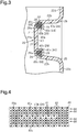
Fig. 2 is a perspective view of the crash box inFig. 1 . -
Fig. 3 is a cross-sectional view of the crash box inFig. 2 . -
Fig. 4 is schematic diagram showing a portion of a multi-layer woven textile inFig. 3 in a state in which a slit is formed. -
Fig. 5A is a perspective view showing a portion of the multi-layer woven textile including a slit inFig. 3 -
Fig. 5B is a perspective view showing a portion of the multi-layer woven textile in a state in which bottom corners have been formed. -
Fig. 5C is a perspective view showing a portion of the multi-layer woven textile inFig. 3 in a state in which the slit is open. -
Fig. 5D is a perspective view showing a portion of the multi-layer woven textile inFig. 3 in a state in which reinforcement fibers are inserted in the slit. -
Fig. 6 is a schematic view of a laminated woven textile according to another example. -
Fig. 7 is a cross-sectional view showing a portion of the bottom corner according to a further example. -
Fig. 8 is a perspective view of the prior art. - One embodiment of a load energy absorber embodied in a crash box will now be described with reference to
Figs. 1 to 5 . - As shown in
Fig. 1 , a leftfront side member 11 and a rightfront side member 11 construct a vehicle body. A rear end of acrash box 20, which serves as a load energy absorber, is fixed by abracket 12 to eachside member 11. Abumper reinforcement 14 is fixed to a front end of each of the twocrash boxes 20. - As shown in
Fig. 2 , thecrash box 20 is formed from a fiber-reinforced resin that includes a multi-layer woventextile 40 as a reinforcement base material and aresin 13 as a matrix. As shown inFig. 4 , the multi-layer woventextile 40 is formed by weavingwarps 41 andwefts 42. The warps 41 are interlaced with thewefts 42 of the multi-layer woventextile 40. The interlacement inseparably bindswoven layers 44 of the multi-layer woventextile 40. Thus, thewarps 41 form joining yarns that join thewoven layers 44 of the multi-layer woventextile 40. In the present embodiment, thewarps 41 and thewefts 42 are formed by carbon fibers that serve as reinforcement fibers. - As shown in
Fig. 2 , thecrash box 20 includes a substantially corrugatedbeam 21. A cross-section of thebeam 21 in a direction in which ridges alternate with furrows is shaped as an open cross-section that includes twogrooves 22 arranged in parallel. With thebeam 21, a direction in which the twogrooves 22 are arranged and a direction in which the ridges alternate with the furrows will be referred to as a transverse direction, and a direction in which thegroove 22 extends will be referred to as a longitudinal direction. Thecrash box 20 is used in a state in which a load is input in the longitudinal direction of thebeam 21. - In the
beam 21, thewarps 41 of the multi-layer woventextile 40 extend in the transverse direction of thebeam 21 in an oscillating state, and thewefts 42 of the multi-layer woventextile 40 extend in the longitudinal direction of thebeam 21 in a non- oscillating state. Thebeam 21 is formed by shaping the multi-layer woventextile 40 to have an open cross-section. - Each
groove 22 of thebeam 21 includes a flat rectangularbottom wall 22a that forms a bottom of thegroove 22 and flatrectangular side walls 22b that project from two long edges of thebottom wall 22a. Thebeam 21 includes a flatrectangular connection portion 22c continuous with thegrooves 22 that are adjacent to each other in the transverse direction. - Further, the
beam 21 includesflanges 22d located at both transverse ends of thebeam 21. Eachflange 22d projects from the long edge of one of theside walls 22b forming eachgroove 22 that is not connected with theconnection portion 22c. Accordingly, one of theflanges 22d, one of thegrooves 22, theconnection portion 22c, the other one ofgrooves 22, and the other one of theflanges 22d are arranged in the transverse direction of thebeam 21. - The
beam 21 includes twobottom corners 24 near thebottom wall 22a of eachgroove 22. Thebottom corner 24 is formed by bending the flat multi-layerwoven textile 40. Thebottom corner 24 is the portion extending in the longitudinal direction of thebeam 21 along a ridge line between thebottom wall 22a and theside wall 22b of eachgroove 22. Further, thebeam 21 includes aconnection portion corner 25 and aflange corner 26. Theconnection portion corner 25 extends along a ridge line between eachgroove 22 and theconnection portion 22c, and theflange corner 26 extends along a ridge line between eachflange 22d and theside wall 22b. - The
crash box 20 includes afirst coupling portion 31 at one longitudinal end of thebeam 21 and asecond coupling portion 32 at the other longitudinal end of thebeam 21. Thefirst coupling portion 31 and thesecond coupling portion 32 are formed by shaping the multi-layer woventextile 40. Thefirst coupling portion 31 and thesecond coupling portion 32 are flat plates. A direction in which surfaces of thefirst coupling portion 31 and thesecond coupling portion 32 extend is orthogonal to the longitudinal direction of thebeam 21. - The
first coupling portion 31 and thesecond coupling portion 32 are bent from each longitudinal end of thebeam 21. Thefirst coupling portion 31 is shaped to project from one of the longitudinal ends of eachflange 22d and theconnection portion 22c in a direction opposite to the direction in which thegrooves 22 are recessed from surfaces of theconnection portion 22c and theflange 22d. Thesecond coupling portion 32 is shaped to project from the other one of the longitudinal ends of eachflange 22d and theconnection portion 22c in the direction in which thegrooves 22 are recessed from the surfaces of theconnection portion 22c and theflange 22d. - The
first coupling portion 31 and thesecond coupling portion 32 includebolt holes 31a and 32a. Abolt 33 is inserted through each bolt hole 31a of thefirst coupling portion 31 and extended through thebumper reinforcement 14. Anut 34 is fastened to thebolt 33 extended through thebumper reinforcement 14 to fix thecrash box 20 to thebumper reinforcement 14. Abolt 33 is inserted through thebolt hole 32a of thesecond coupling portion 32 and extended through thefront side member 11 and thebracket 12. Anut 34 is fastened to thebolt 33, which is extended through thefront side member 11 and thebracket 12 to fix thecrash box 20 to thefront side member 11 with thebracket 12. - The structure for ensuring strength of the
bottom corners 24 in thecrash box 20 will now be described. - As shown in
Fig. 3 , portions defining thebottom wall 22a and theside walls 22b that are continuous with thebottom corners 24 are formed by amain body 40a of the multi-layer woventextile 40. In themain body 40a, thewoven layers 44 of the multi-layer woventextile 40 are all joined by thewarps 41, which serve as the joining yarns (not shown). Eachbottom corner 24 is formed bysegments 40c of the multi-layer woventextile 40. -
Fig. 4 is a schematic diagram of the multi-layer woventextile 40.Fig. 4 shows the multi-layer woventextile 40 prior to the formation of thebottom corner 24. Thesegments 40c are formed by aslit 40b dividing the multi-layer woventextile 40 into two. More specifically, in the multi-layer woventextile 40, thewoven layers 44 that are continuous with thewoven layers 44 of themain body 40a are divided into two by theslit 40b in a thickness direction (lamination direction) of the woven layers 44. The woven layers 44 of each of the twosegments 40c are joined by the warps 41 (joining yarns). The number of thewoven layers 44 in each of the twosegments 40c is one half of that of thewoven layers 44 in themain body 40a. - As shown in
Fig. 3 , eachbottom corner 24 includes theslit 40b that is opened to separate the twosegments 40c from each other. Thebottom corner 24 includes anaccommodation portion 28 surrounded by twosegments 40c. Theaccommodation portion 28 is hollow and formed by opening theslit 40b so that the twosegments 40c define a hollow. Thus, theaccommodation portion 28 is also theslit 40b. Theaccommodation portion 28 extends in the longitudinal direction of thebeam 21. - The
crash box 20 includes areinforcement member 29 that is accommodated in theaccommodation portion 28 of eachbottom corner 24. Thereinforcement member 29 of thecrash box 20 is a bundle ofreinforcement fibers 29a. In thereinforcement member 29, thereinforcement fibers 29a are arranged in a single direction. A fiber axis direction of eachreinforcement fiber 29a is oriented in the longitudinal direction of thebeam 21. In thebeam 21, an orientation angle of thereinforcement fibers 29a is set to 0°. Theaccommodation portion 28 is filled withreinforcement fibers 29a in a state extending straight in the longitudinal direction of thebeam 21. Thereinforcement fibers 29a of thereinforcement member 29 are formed by the same carbon fibers as thewarps 41 and thewefts 42. - The
crash box 20 is used so that a load input direction is the longitudinal direction of thebeam 21. Accordingly, thebottom corners 24 of thecrash box 20 accommodate thereinforcement fibers 29a in a state in which the fiber axis direction of thereinforcement fibers 29a extends in the load input direction. As a result, thereinforcement members 29 increase the strength of thecrash box 20 in the load input direction is so that the strength is higher in thebottom corners 24 than other portions (bottom wall 22a,side walls 22b, andconnection portion corners 25 and 26). - In the
above crash box 20, when an impact load is applied to thebumper reinforcement 14 in a direction shown by arrow Y inFig. 1 , thecrash box 20 is crushed in the longitudinal direction of thebeam 21 to absorb the impact load energy. Thereinforcement fibers 29a of thereinforcement member 29 absorb the impact load energy at thebottom corner 24 of thecrash box 20. In thecrash box 20, the number of thereinforcement fibers 29a in thereinforcement members 29 and the type of thereinforcement fibers 29a are set to absorb the targeted impact load. - A method for manufacturing the
crash box 20 will now be described with reference toFigs. 5A to 5D. Figs. 5A to 5D show only a portion proximate to thebottom corners 24 and do not show other portions. - As shown in
Fig. 5A , the multi-layer woventextile 40 is first woven into a flat rectangular shape. The multi-layer woventextile 40 includes two longitudinal ends, each having anend surface 40d that is rectangular in a front view. A transverse direction of theend surface 40d will be referred to as a thickness-wise direction (lamination direction) of the multi-layer woventextile 40, and a longitudinal direction of theend surface 40d will be referred to as a widthwise direction of the multi-layer woventextile 40. - The thickness of the multi-layer woven
textile 40 is set to be the same as other portions of thebeam 21 excluding thebottom corners 24. The multi-layer woventextile 40 includes theslits 40b at the middle of the multi-layer woventextile 40 in the thickness direction. Theslits 40b allow for separation of thewoven layers 44 that are adjacent to each other in the thickness-wise direction. In the multi-layer woventextile 40, thewoven layers 44 located toward both widthwise sides from eachslit 40b are joined by the warps 41 (now shown) in the thickness-wise direction. Theslit 40b extends over the entire length of the multi-layer woventextile 40 in the longitudinal direction. - Subsequently, the multi-layer woven
textile 40 is shaped to form thebeam 21, thefirst coupling portion 31, and thesecond coupling portion 32. When forming thebeam 21, as shown inFig. 5B , thebottom corners 24 are formed by bending the multi-layer woventextile 40 from a middle part of theslits 40b in the longitudinal direction of theend surface 40d. - Then, as shown in
Fig. 5C , in the multi-layer woventextile 40, the two segments 40C are spread apart in the thickness direction to open theslits 40b and form thehollow accommodation portion 28. - Subsequently, as shown in
Fig. 5D , thereinforcement fibers 29a are inserted in theaccommodation portion 28. Thereinforcement fibers 29a are inserted in a state in which the fiber axis direction of thereinforcement fibers 29a extends straight in the longitudinal direction of the multi-layer woventextile 40 so that theaccommodation portion 28 is filled with thereinforcement fibers 29a. Then, the multi-layer woventextile 40 is impregnated withresin 13 and hardened to complete manufacturing of thecrash box 20. - The above embodiment has the advantages described below.
- (1) The
crash box 20 includes theslit 40b that divides the multi-layer woventextile 40 in the thickness direction at thebottom corners 24. Theslit 40b is opened to form theaccommodation portion 28 that accommodates thereinforcement fibers 29a so as to ensure strength of thebottom corner 24. Accordingly, there is no need to increase the thickness of the entire multi-layer woventextile 40 to ensure strength of thebottom corner 24. Thus, the strength at thebottom corners 24 can be ensured without excessively reinforcing portions other than thebottom corners 24 such as thebottom wall 22a or theside walls 22b. Further, thereinforcement fibers 29a are accommodated in theslit 40b. Thus, there is no need to arrange a separate component at thebottom corner 24 or weld a separate component to prevent removal from thebottom corner 24. As a result, a situation is avoided in which the mass of thecrash box 20 is increased more than necessary or the manufacturing cost of thecrash box 20 is increased. This minimizes increases in cost and mass of thecrash box 20 to minimal and ensures the strength of thebottom corners 24. - (2) The
accommodation portion 28 of eachbottom corner 24 is formed by thesegments 40c of the multi-layer woventextile 40 divided by theslit 40b in the thickness-wise direction. Thus, the formation of theaccommodation portion 28 does not increase the number of components or the mass. - (3) The multi-layer woven
textile 40 is employed as the reinforcement base material of thecrash box 20. When manufacturing the multi-layer woventextile 40, theslit 40b that forms theaccommodation portion 28 can be formed at a portion corresponding to thebottom corner 24. Accordingly, the portion that forms theaccommodation portion 28 can be manufactured with a loom, and the steps for forming theaccommodation portion 28 are not increased. - (4) The
reinforcement member 29 accommodated in theaccommodation portion 28 of eachbottom corner 24 is thereinforcement fibers 29a. Accordingly, the strength of thebottom corner 24 can easily be adjusted to the targeted strength by adjusting the number of thereinforcement fibers 29a. - (5) The fiber axis direction of the
reinforcement fibers 29a extends in the input load direction on thecrash box 20. Accordingly, thereinforcement fibers 29a absorb an impact load in a preferred manner. - (6) The fiber axis direction of the
reinforcement fibers 29a is the same as the longitudinal direction in which thebottom corner 24 continuously extends thereby improving strength of thebottom corner 24. - (7) The reinforcement fibers forming the multi-layer woven
textile 40 and the reinforcement fibers forming thereinforcement member 29 are both carbon fibers. This limits decreases in strength caused by mixing different types of materials in thecrash box 20. - The above embodiment may be modified as described below.
- The reinforcement base material may be a laminated woven
textile 50 instead of the multi-layer woven textile. For example, as shown inFig. 6 , with a plurality of flat woventextiles 51, a portion corresponding to eachbottom corner 24 of thecrash box 20 is divided into two, with one half of the flat woventextiles 51 on one side in the lamination direction (thickness-wise direction) and the other one half of the flat woventextiles 51 on the other side. One half of the flat woventextiles 51 on one side are joined by a joiningyarn 52a in a state separated from the other half of the flat woventextiles 51 on the other side. At other portions of the laminated woventextiles 50 that do not correspond to thebottom corners 24, the flat woventextiles 51 are joined by the joiningyarn 52b. The laminated woventextile 50 includes aslit 53 between one half of the flat woventextiles 51 on one side and the other half of the flat woventextile 51 on the other side. - In the laminated woven
textile 50, thehollow accommodation portion 28 is formed in eachbottom corner 24 when the two halves of the flat woventextile 51 of the two sides are spread apart in the thickness-wise direction to open theslit 53. Thebottom corner 24 is formed by inserting thereinforcement fibers 29a into theaccommodation portion 28. - In the
crash box 20, the portions where thereinforcement members 29 ensure strength is not limited to thebottom corners 24 and may include thebottom wall 22a or theside walls 22b. - The corner having its strength ensured by the
reinforcement member 29 may be at least one of theconnection portion corners 25 or theflange corner 26 in addition to thebottom corners 24. - The corner having its strength ensured by the
reinforcement members 29 may be at least one of theconnection portion corners 25 or theflange corners 26 in addition to thebottom corners 24. - The
reinforcement fibers 29a of thereinforcement member 29 may include reinforcement fibers extending in a fiber axis direction that differs from the longitudinal direction of thebeam 21. For example, thereinforcement member 29 may be reinforcement fibers that includefirst reinforcement fibers 29a andsecond reinforcement fibers 29a. The fiber axis direction of thefirst reinforcement fibers 29a extends in the longitudinal direction of thebeam 21 and is oriented at 0°. The fiber axis direction of thesecond reinforcement fibers 29a, which are fixed in advance to thefirst reinforcement fibers 29a, is oriented at 45° or 90°. - The
reinforcement member 29 does not have to be thereinforcement fibers 29a of carbon fibers and may be, for example, reinforcement fibers of metal fibers. - The
reinforcement fibers 29a of thereinforcement member 29 may be of a different type from that forming the multi-layer woventextiles 40 of thebeam 21. - The
reinforcement fiber 29a of thereinforcement member 29 may have a higher strength than that forming the multi-layer woventextile 40 to increase strength of thebottom corners 24. - The
reinforcement member 29 does not have to be reinforcement fibers and may be a plate of metal or the like. - As shown in
Fig. 7 , twoslits 40b (accommodation portions 28) may be formed in the thickness-wise direction of the multi-layer woventextile 40 or the laminated woventextile 50. Alternatively, three ormore slits 40b may be formed. - The load energy absorber may be used as a pillar reinforcement. In this case, the load input direction would be 90°.
- The load energy absorber may be used as a rocker.
Claims (5)
- A load energy absorber formed by a fiber-reinforced resin, comprising:a multi-layer woven textile or a laminated woven textile serving as a reinforcement base material, wherein the reinforcement base material includes a corner formed by bending the reinforcement base material;a resin serving as a matrix;a slit arranged in the reinforcement base material at a portion where at least the corner is formed;a joining yarn that joins woven layers of the multi-layer woven textile or the laminated woven textile, wherein the joining yarn is configured to join the woven layers in a state in which the woven layers of the multi-layer woven textile or the laminated woven textile are divided into two or more in a thickness-wise direction; anda reinforcement member accommodated inside the slit.
- The load energy absorber according to claim 1, wherein the reinforcement member is a reinforcement fiber.
- The load energy absorber according to claim 2, wherein
the reinforcement fiber is one of a plurality of reinforcement fibers,
the reinforcement fibers are arranged so that fiber axis directions extend in a single direction, and
the main axis direction is a load input direction. - The load energy absorber according to claim 2 or 3, wherein the reinforcement fiber forming the multi-layer woven textile or the laminated woven textile is the same as the reinforcement fiber forming the reinforcement member.
- The load energy absorber according to any one of claims 1 to 4, wherein the load energy absorber is a crash box.
Applications Claiming Priority (2)
| Application Number | Priority Date | Filing Date | Title |
|---|---|---|---|
| JP2016133529A JP6558316B2 (en) | 2016-07-05 | 2016-07-05 | Load energy absorber |
| PCT/JP2017/021841 WO2018008340A1 (en) | 2016-07-05 | 2017-06-13 | Load energy-asborber |
Publications (2)
| Publication Number | Publication Date |
|---|---|
| EP3483468A1 true EP3483468A1 (en) | 2019-05-15 |
| EP3483468A4 EP3483468A4 (en) | 2019-07-03 |
Family
ID=60912684
Family Applications (1)
| Application Number | Title | Priority Date | Filing Date |
|---|---|---|---|
| EP17823947.1A Withdrawn EP3483468A4 (en) | 2016-07-05 | 2017-06-13 | Load energy-absorber |
Country Status (5)
| Country | Link |
|---|---|
| US (1) | US20190323574A1 (en) |
| EP (1) | EP3483468A4 (en) |
| JP (1) | JP6558316B2 (en) |
| CN (1) | CN109416100A (en) |
| WO (1) | WO2018008340A1 (en) |
Families Citing this family (5)
| Publication number | Priority date | Publication date | Assignee | Title |
|---|---|---|---|---|
| JP2019151130A (en) * | 2018-02-28 | 2019-09-12 | マツダ株式会社 | Vehicle impact absorption structure |
| JP6756792B2 (en) * | 2018-09-27 | 2020-09-16 | 本田技研工業株式会社 | Rear structure of the car body |
| JP7260777B2 (en) * | 2019-05-31 | 2023-04-19 | キョーラク株式会社 | shock absorber |
| GB2585012B (en) * | 2019-06-24 | 2021-11-17 | Jaguar Land Rover Ltd | Securing method for composite structure post-crash |
| CN117565809B (en) * | 2024-01-12 | 2024-04-30 | 广东粤港澳大湾区黄埔材料研究院 | Composite material energy-absorbing box and anti-collision beam assembly |
Family Cites Families (14)
| Publication number | Priority date | Publication date | Assignee | Title |
|---|---|---|---|---|
| US3487518A (en) * | 1965-08-12 | 1970-01-06 | Henry Hopfeld | Method for making a reinforced structural member |
| JP3486034B2 (en) * | 1995-12-25 | 2004-01-13 | 株式会社豊田自動織機 | Three-dimensional fiber structure |
| JP2009235655A (en) * | 2008-03-28 | 2009-10-15 | Unitika Textiles Ltd | Woven fabric |
| JP2010152782A (en) * | 2008-12-26 | 2010-07-08 | Sony Corp | Electronic device |
| BR112013018135A2 (en) * | 2011-04-04 | 2019-09-24 | Global Safety Txtiles Gmbh | textile element for structure and method for fabrication thereof |
| US8440045B2 (en) * | 2011-09-14 | 2013-05-14 | Sikorsky Aircraft Corporation | Conformal deltoid noodle for a composite structure |
| EP2787241A4 (en) * | 2011-11-28 | 2015-07-08 | Teijin Ltd | Shock absorption member |
| JP5776537B2 (en) * | 2011-12-26 | 2015-09-09 | トヨタ車体株式会社 | Shock absorber for vehicle |
| EP3009467B1 (en) * | 2013-06-12 | 2018-12-05 | Honda Motor Co., Ltd. | Fiber-reinforced resin member |
| WO2015119206A1 (en) * | 2014-02-06 | 2015-08-13 | 帝人株式会社 | Resin shock-absorbing member and vehicle component |
| US11137044B2 (en) * | 2014-02-24 | 2021-10-05 | Teijin Limited | Resin-made impact absorption member |
| JP5962724B2 (en) * | 2014-09-04 | 2016-08-03 | 株式会社豊田自動織機 | Energy absorbing member |
| JP5880671B1 (en) * | 2014-11-28 | 2016-03-09 | 株式会社豊田自動織機 | Shock absorber and method for producing shock absorber |
| US9682674B2 (en) * | 2014-12-11 | 2017-06-20 | Shape Corp. | Pultruded beam, and apparatus and methods for manufacturing |
-
2016
- 2016-07-05 JP JP2016133529A patent/JP6558316B2/en not_active Expired - Fee Related
-
2017
- 2017-06-13 WO PCT/JP2017/021841 patent/WO2018008340A1/en unknown
- 2017-06-13 EP EP17823947.1A patent/EP3483468A4/en not_active Withdrawn
- 2017-06-13 CN CN201780039830.7A patent/CN109416100A/en active Pending
- 2017-06-13 US US16/312,659 patent/US20190323574A1/en not_active Abandoned
Also Published As
| Publication number | Publication date |
|---|---|
| JP2018003994A (en) | 2018-01-11 |
| JP6558316B2 (en) | 2019-08-14 |
| EP3483468A4 (en) | 2019-07-03 |
| WO2018008340A1 (en) | 2018-01-11 |
| WO2018008340A8 (en) | 2018-12-27 |
| US20190323574A1 (en) | 2019-10-24 |
| CN109416100A (en) | 2019-03-01 |
Similar Documents
| Publication | Publication Date | Title |
|---|---|---|
| EP3483468A1 (en) | Load energy-absorber | |
| EP2965953B1 (en) | Bumper device for automobile | |
| US9919668B2 (en) | Vehicle energy absorption structure and energy absorption member | |
| CN105008210A (en) | Frame structure for vehicle | |
| US10286955B2 (en) | Rear vehicle-body structure of vehicle | |
| KR20200091665A (en) | Vehicle rear chassis module | |
| KR20150145356A (en) | Bumper back beam for vehicle | |
| CN109955904B (en) | Floor structure of vehicle body | |
| JP5734174B2 (en) | Auto body structure | |
| US20150137538A1 (en) | Bumper back beam made of composite material and having improved energy absorption rate, and bumper including same | |
| CN113942584A (en) | Beam lap joint reinforcing structure and rear wall body-in-white beam | |
| JP2013212731A (en) | Vehicle | |
| KR102255692B1 (en) | Imapact beam | |
| JP6686700B2 (en) | Flanges for fiber-reinforced resin parts and flange structure for fiber-reinforced resin parts | |
| WO2019224973A1 (en) | Body side panel | |
| JP2020175768A (en) | Vehicle structure and vehicle manufacturing method | |
| CN205381315U (en) | Body structure and have vehicle of this body structure | |
| CN109070820B (en) | Energy absorbing structure | |
| CN107848474B (en) | Beam for bumper | |
| JP7416657B2 (en) | composite structure | |
| JP6112686B2 (en) | Auto body structure | |
| KR102023131B1 (en) | Rear bumper back beam for vehicles | |
| JP2018144631A (en) | Bumper for vehicle | |
| US9840285B2 (en) | Front vehicle body and method of fabricating front vehicle body | |
| CN214929549U (en) | Impact absorbing member |
Legal Events
| Date | Code | Title | Description |
|---|---|---|---|
| PUAI | Public reference made under article 153(3) epc to a published international application that has entered the european phase |
Free format text: ORIGINAL CODE: 0009012 |
|
| 17P | Request for examination filed |
Effective date: 20181211 |
|
| AK | Designated contracting states |
Kind code of ref document: A1 Designated state(s): AL AT BE BG CH CY CZ DE DK EE ES FI FR GB GR HR HU IE IS IT LI LT LU LV MC MK MT NL NO PL PT RO RS SE SI SK SM TR |
|
| AX | Request for extension of the european patent |
Extension state: BA ME |
|
| A4 | Supplementary search report drawn up and despatched |
Effective date: 20190531 |
|
| RIC1 | Information provided on ipc code assigned before grant |
Ipc: F16F 7/00 20060101AFI20190524BHEP Ipc: B60R 19/34 20060101ALI20190524BHEP Ipc: B29C 70/86 20060101ALI20190524BHEP Ipc: F16F 7/12 20060101ALI20190524BHEP Ipc: B29C 70/22 20060101ALI20190524BHEP Ipc: B29C 70/20 20060101ALI20190524BHEP |
|
| DAV | Request for validation of the european patent (deleted) | ||
| DAX | Request for extension of the european patent (deleted) | ||
| STAA | Information on the status of an ep patent application or granted ep patent |
Free format text: STATUS: THE APPLICATION HAS BEEN WITHDRAWN |
|
| 17Q | First examination report despatched |
Effective date: 20200929 |
|
| 18W | Application withdrawn |
Effective date: 20201002 |