EP3483380A1 - A method for determining a fully extended position of a screening body of a screening device - Google Patents
A method for determining a fully extended position of a screening body of a screening device Download PDFInfo
- Publication number
- EP3483380A1 EP3483380A1 EP18205241.5A EP18205241A EP3483380A1 EP 3483380 A1 EP3483380 A1 EP 3483380A1 EP 18205241 A EP18205241 A EP 18205241A EP 3483380 A1 EP3483380 A1 EP 3483380A1
- Authority
- EP
- European Patent Office
- Prior art keywords
- screening
- screening body
- spring element
- roller tube
- electric motor
- Prior art date
- Legal status (The legal status is an assumption and is not a legal conclusion. Google has not performed a legal analysis and makes no representation as to the accuracy of the status listed.)
- Granted
Links
Images


Classifications
-
- E—FIXED CONSTRUCTIONS
- E06—DOORS, WINDOWS, SHUTTERS, OR ROLLER BLINDS IN GENERAL; LADDERS
- E06B—FIXED OR MOVABLE CLOSURES FOR OPENINGS IN BUILDINGS, VEHICLES, FENCES OR LIKE ENCLOSURES IN GENERAL, e.g. DOORS, WINDOWS, BLINDS, GATES
- E06B9/00—Screening or protective devices for wall or similar openings, with or without operating or securing mechanisms; Closures of similar construction
- E06B9/56—Operating, guiding or securing devices or arrangements for roll-type closures; Spring drums; Tape drums; Counterweighting arrangements therefor
- E06B9/60—Spring drums operated only by closure members
-
- E—FIXED CONSTRUCTIONS
- E06—DOORS, WINDOWS, SHUTTERS, OR ROLLER BLINDS IN GENERAL; LADDERS
- E06B—FIXED OR MOVABLE CLOSURES FOR OPENINGS IN BUILDINGS, VEHICLES, FENCES OR LIKE ENCLOSURES IN GENERAL, e.g. DOORS, WINDOWS, BLINDS, GATES
- E06B9/00—Screening or protective devices for wall or similar openings, with or without operating or securing mechanisms; Closures of similar construction
- E06B9/24—Screens or other constructions affording protection against light, especially against sunshine; Similar screens for privacy or appearance; Slat blinds
- E06B9/40—Roller blinds
- E06B9/42—Parts or details of roller blinds, e.g. suspension devices, blind boxes
-
- E—FIXED CONSTRUCTIONS
- E06—DOORS, WINDOWS, SHUTTERS, OR ROLLER BLINDS IN GENERAL; LADDERS
- E06B—FIXED OR MOVABLE CLOSURES FOR OPENINGS IN BUILDINGS, VEHICLES, FENCES OR LIKE ENCLOSURES IN GENERAL, e.g. DOORS, WINDOWS, BLINDS, GATES
- E06B9/00—Screening or protective devices for wall or similar openings, with or without operating or securing mechanisms; Closures of similar construction
- E06B9/56—Operating, guiding or securing devices or arrangements for roll-type closures; Spring drums; Tape drums; Counterweighting arrangements therefor
- E06B9/68—Operating devices or mechanisms, e.g. with electric drive
- E06B9/72—Operating devices or mechanisms, e.g. with electric drive comprising an electric motor positioned inside the roller
-
- E—FIXED CONSTRUCTIONS
- E06—DOORS, WINDOWS, SHUTTERS, OR ROLLER BLINDS IN GENERAL; LADDERS
- E06B—FIXED OR MOVABLE CLOSURES FOR OPENINGS IN BUILDINGS, VEHICLES, FENCES OR LIKE ENCLOSURES IN GENERAL, e.g. DOORS, WINDOWS, BLINDS, GATES
- E06B9/00—Screening or protective devices for wall or similar openings, with or without operating or securing mechanisms; Closures of similar construction
- E06B9/56—Operating, guiding or securing devices or arrangements for roll-type closures; Spring drums; Tape drums; Counterweighting arrangements therefor
- E06B9/68—Operating devices or mechanisms, e.g. with electric drive
-
- E—FIXED CONSTRUCTIONS
- E06—DOORS, WINDOWS, SHUTTERS, OR ROLLER BLINDS IN GENERAL; LADDERS
- E06B—FIXED OR MOVABLE CLOSURES FOR OPENINGS IN BUILDINGS, VEHICLES, FENCES OR LIKE ENCLOSURES IN GENERAL, e.g. DOORS, WINDOWS, BLINDS, GATES
- E06B9/00—Screening or protective devices for wall or similar openings, with or without operating or securing mechanisms; Closures of similar construction
- E06B9/56—Operating, guiding or securing devices or arrangements for roll-type closures; Spring drums; Tape drums; Counterweighting arrangements therefor
- E06B9/80—Safety measures against dropping or unauthorised opening; Braking or immobilising devices; Devices for limiting unrolling
- E06B9/82—Safety measures against dropping or unauthorised opening; Braking or immobilising devices; Devices for limiting unrolling automatic
-
- E—FIXED CONSTRUCTIONS
- E06—DOORS, WINDOWS, SHUTTERS, OR ROLLER BLINDS IN GENERAL; LADDERS
- E06B—FIXED OR MOVABLE CLOSURES FOR OPENINGS IN BUILDINGS, VEHICLES, FENCES OR LIKE ENCLOSURES IN GENERAL, e.g. DOORS, WINDOWS, BLINDS, GATES
- E06B9/00—Screening or protective devices for wall or similar openings, with or without operating or securing mechanisms; Closures of similar construction
- E06B9/56—Operating, guiding or securing devices or arrangements for roll-type closures; Spring drums; Tape drums; Counterweighting arrangements therefor
- E06B9/80—Safety measures against dropping or unauthorised opening; Braking or immobilising devices; Devices for limiting unrolling
- E06B9/82—Safety measures against dropping or unauthorised opening; Braking or immobilising devices; Devices for limiting unrolling automatic
- E06B9/88—Safety measures against dropping or unauthorised opening; Braking or immobilising devices; Devices for limiting unrolling automatic for limiting unrolling
-
- E—FIXED CONSTRUCTIONS
- E06—DOORS, WINDOWS, SHUTTERS, OR ROLLER BLINDS IN GENERAL; LADDERS
- E06B—FIXED OR MOVABLE CLOSURES FOR OPENINGS IN BUILDINGS, VEHICLES, FENCES OR LIKE ENCLOSURES IN GENERAL, e.g. DOORS, WINDOWS, BLINDS, GATES
- E06B9/00—Screening or protective devices for wall or similar openings, with or without operating or securing mechanisms; Closures of similar construction
- E06B9/56—Operating, guiding or securing devices or arrangements for roll-type closures; Spring drums; Tape drums; Counterweighting arrangements therefor
- E06B9/68—Operating devices or mechanisms, e.g. with electric drive
- E06B2009/6809—Control
- E06B2009/6818—Control using sensors
- E06B2009/6854—Control using sensors sensing torque
-
- E—FIXED CONSTRUCTIONS
- E06—DOORS, WINDOWS, SHUTTERS, OR ROLLER BLINDS IN GENERAL; LADDERS
- E06B—FIXED OR MOVABLE CLOSURES FOR OPENINGS IN BUILDINGS, VEHICLES, FENCES OR LIKE ENCLOSURES IN GENERAL, e.g. DOORS, WINDOWS, BLINDS, GATES
- E06B9/00—Screening or protective devices for wall or similar openings, with or without operating or securing mechanisms; Closures of similar construction
- E06B9/56—Operating, guiding or securing devices or arrangements for roll-type closures; Spring drums; Tape drums; Counterweighting arrangements therefor
- E06B9/68—Operating devices or mechanisms, e.g. with electric drive
- E06B2009/6809—Control
- E06B2009/6872—Control using counters to determine shutter position
-
- E—FIXED CONSTRUCTIONS
- E06—DOORS, WINDOWS, SHUTTERS, OR ROLLER BLINDS IN GENERAL; LADDERS
- E06B—FIXED OR MOVABLE CLOSURES FOR OPENINGS IN BUILDINGS, VEHICLES, FENCES OR LIKE ENCLOSURES IN GENERAL, e.g. DOORS, WINDOWS, BLINDS, GATES
- E06B9/00—Screening or protective devices for wall or similar openings, with or without operating or securing mechanisms; Closures of similar construction
- E06B9/56—Operating, guiding or securing devices or arrangements for roll-type closures; Spring drums; Tape drums; Counterweighting arrangements therefor
- E06B9/68—Operating devices or mechanisms, e.g. with electric drive
- E06B9/72—Operating devices or mechanisms, e.g. with electric drive comprising an electric motor positioned inside the roller
- E06B2009/725—Operating devices or mechanisms, e.g. with electric drive comprising an electric motor positioned inside the roller with epicyclic or planetary gear train
-
- G—PHYSICS
- G01—MEASURING; TESTING
- G01P—MEASURING LINEAR OR ANGULAR SPEED, ACCELERATION, DECELERATION, OR SHOCK; INDICATING PRESENCE, ABSENCE, OR DIRECTION, OF MOVEMENT
- G01P3/00—Measuring linear or angular speed; Measuring differences of linear or angular speeds
- G01P3/42—Devices characterised by the use of electric or magnetic means
- G01P3/44—Devices characterised by the use of electric or magnetic means for measuring angular speed
- G01P3/46—Devices characterised by the use of electric or magnetic means for measuring angular speed by measuring amplitude of generated current or voltage
- G01P3/465—Devices characterised by the use of electric or magnetic means for measuring angular speed by measuring amplitude of generated current or voltage by using dynamo-electro tachometers or electric generator
Definitions
- the present invention relates to a method for determining a fully extended position of a screening body of a screening device of the type adapted for mounting on a frame structure with frame members comprising top and bottom members as well as side members and lining an opening in a building, in particular a door or a window, the screening device comprising a top element, the top element comprising a roller tube, a screening body attached to the roller tube, a first end section comprising a first spring element and a second end section comprising a second spring element, a bottom element attached to the screening body, an end stop adapted for abutment with the bottom element in a fully extended position of the screening body, in which all of the screening body is rolled off of the roller tube, an electric motor connected to and adapted for rotating the roller tube, the first spring element and the second spring element such as to drive the screening body between a fully retracted position, in which all of the screening body is rolled onto the roller tube and the fully extended position of the screening body while tensioning or relaxing the first spring element and the second
- the invention further relates to a method for operating a screening device of the above type following determination of the fully extended position of the screening body of the screening device.
- connection operation used in the connection operation of the screening device is intended to mean the process of moving the screening body from a fully retracted position of the screening body, in which all of the screening body is rolled onto the roller tube, to a partly or fully extended position of the screening body and back to the fully retracted position of the screening body.
- a well-known problem in relation to screening devices of the above mentioned type lies in the risk of the screening body of the screening device sagging and/or wrinkling during operation. If the screening body of the screening device is caused to sag and/or wrinkle during operation there is a risk of the screening body getting damaged or getting stuck. This in turn may damage or jam the driving mechanism. Furthermore, the appearance of the screening device in the fully extended position may become aesthetically unpleasing for the user. In screening devices operated by means of an electric motor it is therefore essential that the control system is enabled to determine and/or detect the fully extended position of the screening body of the screening device.
- EP 3 121 364 A1 describes a method for controlling a driving unit of a roller shutter in which a learning process is employed in order to enable the controller to detect the fully extended position and the fully retracted position of the screening body.
- the controller drives the screening body between its fully extended position and its fully retracted position a predetermined number of times, such as four times, and in doing so detects when a threshold of for instance a torque or an intensity of the current drawn by the electric motor driving the screening body is exceeded within a predetermined time span and registers the corresponding position of the screening body.
- the position of the screening body may, for instance, be defined as a number of revolutions of the roller tube of the screening device.
- the prior art methods have the drawback of being excessively cumbersome and time consuming to perform. Furthermore, the prior art methods pose a significant risk of inaccurate detection of the fully extended position of the screening body. Therefore, in the prior art methods, a risk of sagging and/or wrinkling of the screening body of the screening device in the fully extended position is nevertheless still occurring, and in consequence the screening body may still wrinkle or get stuck.
- step e) includes performing the said measurement over a time span taking into account a delay in time with respect to the point of time at which the electric motor is stopped in step d), with which the release of a tension of the first spring element and the second spring element corresponding to the difference between the first tension level, T 1 , and the second tension level, T 2 , occurs or may occur.
- the method according to the invention comprises the further steps of counting the number of operations of the screening device performed, and repeating steps a) to g) following a predetermined number of operations of the screening device to obtain a corrected version, R corr , of the value R.
- the predetermined number of operations is 200, 500 or 1000.
- the above and other objects are achieved, also for operations of the screening device following the first operation in which the fully extended position of the screening body of the screening device is determined, by means of a method for operating a screening device of the above type following determination of the fully extended position of the screening body of the screening device, where the method comprises the steps of performing the method according to the first aspect of the invention to obtain a value R, and, for operations of the screening device following the performance of the method according to the first aspect of the invention, controlling the electric motor to drive the screening body and the bottom element from the fully retracted position of the screening body towards the fully extended position of the screening body by moving the roller tube a number of revolutions being equal to the value R or equal to a fraction of the value R.
- the above and other objects are achieved, also for operations of the screening device following an operation in which the fully extended position of the screening body of the screening device is re-determined, by means of a method for operating a screening device of the above type following redetermination of the fully extended position of the screening body of the screening device, where the method comprises the steps of performing the method according to the first aspect of the invention to obtain a corrected version, R corr , of the value R, and, for operations of the screening device following the performance of the method according to the first aspect of the invention, controlling the electric motor to drive the screening body and the bottom element from the fully retracted position of the screening body towards the fully extended position of the screening body by moving the roller tube a number of revolutions being equal to the corrected version, R corr , of the value R or being equal to a fraction of the corrected version, R corr , of the value R.
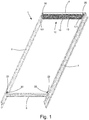
- a first embodiment of a screening device 12 mounted in a roof window 1 is shown.
- the roof window 1 shown in Fig. 1 is adapted for mounting in an inclined roof.
- the roof window 1 comprises a frame 2 and an openable sash supporting a glass pane.
- the openable sash and the glass pane are omitted on Fig. 1 .
- the roof window is of the kind shown and described in for instance Applicant's WO 2015/028031 A1 ; however, the principle underlying the invention is applicable to all kinds of roof windows, in that the sash may be top hung, centre hung, have hinge axis at position between the top and centre or of the kind that is top hung during normal operation but which pivots for cleaning by means of an intermediate frame.
- the frame 2 comprises a top frame member 4, a bottom frame member 5 and two side frame members 6, 7.
- the sash comprises a top sash member, a bottom sash member and two side sash members.
- the screening device 12 is in the embodiment shown is installed at the top frame member 4 of the roof window 1.
- the screening device 12 may in principle be any feasible type of screening device 12.
- the screening device is a roller blind.
- the screening device may be a roller shutter.
- a screening device 12 according to the invention may also be mounted at other frame members of the roof window, or on a façade window or a door.
- the screening device 12 generally comprises a screening body 14 and a top element 13 with two end sections 16, 17.
- the screening device 12 is connected to the side frame members 6 and 7 at the end sections 16, 17 of the top element 13 by means of supporting means including a set of mounting brackets (not visible in Figs. 1 and 2 ) fastened to the respective side frame member 6, 7 cooperating with end sections 16, 17 as will be described in further detail below.
- the set of mounting bracket may be fastened to the frame at the factory such that the roof window is prepared for subsequent mounting of the screening device, and possibly the screening device 12 may be pre-mounted at the factory as well.
- the screening body 14 is wound on a roller tube indicated by reference numeral 15 in Figs. 2 and 3 , but in fact hidden behind the screening body 14.
- the screening device 12 further comprises a bottom bar 19 and two winding wheels 20.
- the winding wheels 20 are adapted for receiving a respective wire 21 ( Fig. 3 ) which is wound onto the winding wheels 20 when pulling up the screening body 14 and out from the winding wheels 20 when pulling down the screening body 14.
- the screening device 12 further comprises return pulleys 22 ( Fig. 3 ) around which the wires 21 are lead and returned to the bottom bar 19.
- the screening arrangement further comprises a motor 18, in the embodiment shown an electric motor, adapted for driving the screening device 12.
- the motor 18 is connected to the winding wheels 20 via a suitable transmission such as to enable moving the screening body 14 between a fully retracted position, in which the screening body 14 does not cover the glass pane of the window, and in the embodiment shown is wound onto a roller tube 15, and a fully extended position, in which the screening body 14 covers substantially all of the glass pane of the window.
- the motor 18 comprises in the embodiment shown a tachometer 181, a printed circuit board 182 and a planetary gear 183. The motor 18 is connected to and adapted for rotating the roller tube 15.
- the motor 18 is connected to a rotatable cap 184, which in turn is connected to the roller tube 15 at an inner side of the roller tube 15 such that the motor 18 in operation may rotate the roller tube 15.
- the printed circuit board 182 comprises a data storage device adapted and arranged for being in data communication with the tachometer 181 and a control device adapted and arranged for being in data communication with the tachometer 181 and with the data storage device.
- each end section 16 and 17 generally comprises a respective end piece 161 and 171, a respective inner piece (not shown on Fig. 4 ) and a respective rod element (not visible on Fig. 4 ).
- the rod element of the end section 16 connects the end piece 161 and the inner piece of the end section 16, and the rod element of the end section 17 connects the end piece 171 and the inner piece of the end section 17.
- the end piece 161 and the inner piece of the end section 16 are connected to opposite longitudinal ends of the rod element of the end section 16, and the end piece 171 and the inner piece of the end section 17 are connected to opposite longitudinal ends of the rod element of the end section 17.
- the end section 16 further comprises a spring element 164 having one end attached to a first rotatable holder 166 and the opposite end attached to a second rotatable holder 167 ( Fig. 5 ), which in turn is attached fixedly to the winding wheel 20.
- a rotatable element 165 or ring is arranged on the second rotatable holder 167.
- the rotatable element 165 is freely rotatable with respect to the second rotatable holder 167.
- the rotatable element 165 is not attached to the spring element 164.
- the rotatable element 165 can thus rotate freely with respect to the spring element 164.
- the rotatable element 165 is in the assembled condition of the screening device 12 attached to the roller tube 15.
- the motor 18 is furthermore connected to and adapted for rotating the spring element 164. More particularly, the motor 18 is connected to the rotatable element 165, which in turn is connected to the roller tube 15 and the spring element 164 such that the motor 18 in operation may rotate the spring element 164.
- the spring element 164, the second rotatable holder 167 and the rotatable element 165 are arranged concentrically on the rod element 163 of the end section 16 between the end piece 161 and the inner piece 162.
- the first rotatable holder 166 is arranged concentrically on the rod element 163 of the end section 16, optionally on a seat or bearing 168, between the end piece 161 and the inner piece 162. Also, the winding wheel 20 is arranged concentrically with respect to the rod element 163 adjacent to the end piece 161. Furthermore, the rotatable holder 166 is in the assembled condition of the screening device 12 attached to an inner surface of the roller tube 15. The rotatable holder 166 can thus rotate with the roller tube 15.
- the end section 17 further comprises a spring element 174 having one end attached to a first rotatable holder 176 and the opposite end attached to a second rotatable holder (not visible), which in turn is attached to the winding wheel 20.
- a rotatable element 175 or ring is arranged on the second rotatable holder.
- the rotatable element 175 is not attached to the spring element 174.
- the rotatable element 175 is in the assembled condition of the screening device 12 attached to the roller tube 15.
- the spring element 174, the first rotatable holder 176, the second rotatable holder and the rotatable element 175 are arranged concentrically on the rod element of the end section 17 between the end piece 171 and the inner piece (not shown).
- the winding wheel 20 is arranged concentrically on the rod element (not visible) adjacent to the end piece 171. Furthermore, the rotatable holder 176 is in the assembled condition of the screening device 12 attached to an inner surface of the roller tube 15. Thus, the motor 18 is likewise connected to and adapted for rotating the spring element 174.
- the respective spring element 164, 174 and the respective winding wheel 20 may rotate together.
- the spring elements 164 and 174 are in an embodiment a helical spring.
- the spring elements 164 and 174 have an inherent pretension state.
- One of the end sections 16 and 17, in the embodiment shown the end section 16, is furthermore connected to the motor 18. More particularly, the motor 18, in the embodiment shown (cf. Fig. 5 ) the printed circuit board 182 of the motor 18, is attached to the inner piece 162 of the end section 16 in a non-rotatable manner. Thereby, the inner piece 162, the printed circuit board 182 and the rod element 163 are connected in such a manner that they form one rigid element.
- the rotatable element 165 and 175, respectively, as well as the end cap 184 are not attached to the spring element 164 and 174, respectively.
- the rotatable element 165 and 175, respectively, as well as the end cap 184 rotate, during operation of the motor 18 and thus during operation of the screening device 12, with the roller tube 15.
- the first rotatable holder 166 and 176, respectively, and the respective second rotatable holder are attached to the spring element 164 and 174, respectively.
- the first rotatable holder 166 and 176, respectively, and the second rotatable holder 167 and 177, respectively, also rotate, during operation of the motor 18 and thus during operation of the screening device 12, with the roller tube 15.
- the spring element 164 and 174, respectively also rotates, namely in such a way that the opposite ends of the spring element 164 and 174, respectively, rotate in the same direction but at different speeds.
- the speed of rotation is dependent on the position of the bottom element 19 of the screening device 12.
- the diameter of the wire 21 on the winding wheel 20 is smaller than the diameter of the screening body 14 on the roller tube 15.
- the diameter of the wire 21 on the winding wheel 20 is approximately equal to the diameter of the screening body 14 on the roller tube 15.
- the method according to the invention is intended to be performed at least the first time after mounting that the screening body is moved from the fully retracted position to the fully extended position such as to calibrate the screening device.
- the method may be repeated at predetermined intervals during the life time of the screening device such as to recalibrate the screening device.
- a first step 100 the roller tube 15 of the screening device 12 is rotated by means of the electric motor 18 such as to drive the screening body 14 and the bottom bar or element 19 from the fully retracted position to the fully extended position of the screening body 14.
- the first spring element 164 and the second spring element 174 will both be tensioned to a first tension level, T 1 , due to the opposite ends of the spring element 164 and 174, respectively, being rotated in the same direction but at different speeds.
- the bottom element 19 abuts the end stop 23.
- the first tension level, T 1 is above a tension level, T IP , corresponding to the inherent pretension of the first spring element 164 and the second spring element 174.
- a breaking current being detected. More precisely, the electric motor 18 is stopped when the current drawn by the electric motor 18 reaches a breaking current corresponding to a predetermined current level above the current level needed to drive the screening device 12 at standard operating conditions, i.e. at any position between the fully retracted position and the fully extended position.
- the first spring element 164 and the second spring element 174 will be tensioned to a second tension level, T 2 , which is above the first tension level, T 1 .
- the screening body 14 and the bottom element 19 will in effect be positioned a small distance beyond the fully extended position. Therefore, the screening body 14 may, to some extend be caused to hang.
- a third step 102 the number of revolutions, R d , of the roller tube necessary to drive the screening body 14 and the bottom element 19 from the fully retracted position to the position of the screening body 1 at which the motor 18 is stopped in step 101 is measured by means of the tachometer 181 of the electric motor 18.
- the third step 102 is in practice performed during the performance of the first step 100.
- a fourth step 103 the measured number of revolutions, R d , is transmitted to and stored in the data storage device of the control unit of the screening device 12.
- the control unit, and thus the data storage device may be a unit separate from the electric motor 18, or it may be integrated on the printed circuit board 182 of the electric motor 18.
- a fifth step 104 the number of revolutions, R b , of the roller tube 15, that a release of a tension of the first spring element 164 and the second spring element 174 corresponding to the difference, ⁇ T, between the first tension level, T 1 , and the second tension level, T 2 , will cause the roller tube 15 and thus the screening body 14 to move back towards the fully retracted position is measured by means of the tachometer 181 of the electric motor 18.
- the electric motor 18 is stopped or off during the performance of the fifth step 104. Also, the winding wheels 20 do not rotate or move during the performance of the fifth step 104.
- a sixth step 105 the measured number of revolutions, R b , is stored in the data storage device of the control unit of the screening device 12.
- a value R R d - R b is calculated and stored in the data storage device of the printed circuit board 182.
- the value R thus obtained is read by the control unit of the screening device 12 as corresponding to the screening body 14 being in its fully extended position and is used in subsequent operations of the screening body 14 to denote that the screening body 14 has reached its fully extended position.
- step 107 the number of operations of the screening device 12 are counted, and the first to seventh steps 100-106 are repeated 108 following the occurrence of a predetermined number of operations of the screening device 12 to obtain a corrected version, R corr , of the value R.
- the predetermined number of operations of the screening device may be any suitable number upon which redetermination of the fully extended position of the screening body of the screening device may be needed, nonlimiting examples being 200, 500 or 1000 operations.
- the corrected version, R corr , of the value R is stored in the data storage device of the printed circuit board 182 by replacing or overwriting the existing value R and/or a previously stored corrected version of the value R.
- a method according to the invention for operating a screening device 12 may comprise performing the first to seventh steps 100-106 described above, and for operations following thereupon controlling 109 the electric motor 18 to drive the screening body 14 and the bottom element 19 from the fully retracted position to the fully extended position in dependence of the value R calculated and stored in the seventh step 106.
- the electric motor 18 may be controlled to drive the screening body 14 and the bottom element 19 from the fully retracted position of the screening body 14 towards the fully extended position of the screening body 14 by moving the roller tube 15 a number of revolutions being equal to the value R or equal to a fraction of the value R calculated and stored in the seventh step 106.
- the method for operating a screening device 12 may in an alternative version comprise the steps of performing the first to eighth steps 100-107 described above, and for operations following thereupon controlling 109 the electric motor 18 to drive the screening body 14 and the bottom element 19 from the fully retracted position to the fully extended position in dependence of the corrected version, R corr , of the value R calculated and stored in the eighth step 107.
- the electric motor 18 may be controlled to drive the screening body 14 and the bottom element 19 from the fully retracted position of the screening body 14 towards the fully extended position of the screening body 14 by moving the roller tube 15 a number of revolutions being equal to the corrected version, R corr , of the value R or equal to a fraction of the corrected version, R corr , of the value R calculated and stored in the eighth step 107.
Landscapes
- Engineering & Computer Science (AREA)
- Structural Engineering (AREA)
- Architecture (AREA)
- Civil Engineering (AREA)
- Operating, Guiding And Securing Of Roll- Type Closing Members (AREA)
- Power-Operated Mechanisms For Wings (AREA)
Abstract
Description
- The present invention relates to a method for determining a fully extended position of a screening body of a screening device of the type adapted for mounting on a frame structure with frame members comprising top and bottom members as well as side members and lining an opening in a building, in particular a door or a window, the screening device comprising a top element, the top element comprising a roller tube, a screening body attached to the roller tube, a first end section comprising a first spring element and a second end section comprising a second spring element, a bottom element attached to the screening body, an end stop adapted for abutment with the bottom element in a fully extended position of the screening body, in which all of the screening body is rolled off of the roller tube, an electric motor connected to and adapted for rotating the roller tube, the first spring element and the second spring element such as to drive the screening body between a fully retracted position, in which all of the screening body is rolled onto the roller tube and the fully extended position of the screening body while tensioning or relaxing the first spring element and the second spring element, the electric motor comprising a tachometer, and a control unit adapted for controlling the electric motor, the control unit comprising a data storage device.
- The invention further relates to a method for operating a screening device of the above type following determination of the fully extended position of the screening body of the screening device.
- As used herein the term "operation" used in the connection operation of the screening device is intended to mean the process of moving the screening body from a fully retracted position of the screening body, in which all of the screening body is rolled onto the roller tube, to a partly or fully extended position of the screening body and back to the fully retracted position of the screening body.
- A well-known problem in relation to screening devices of the above mentioned type lies in the risk of the screening body of the screening device sagging and/or wrinkling during operation. If the screening body of the screening device is caused to sag and/or wrinkle during operation there is a risk of the screening body getting damaged or getting stuck. This in turn may damage or jam the driving mechanism. Furthermore, the appearance of the screening device in the fully extended position may become aesthetically unpleasing for the user. In screening devices operated by means of an electric motor it is therefore essential that the control system is enabled to determine and/or detect the fully extended position of the screening body of the screening device.
- In the prior art, various methods have been suggested in an attempt of alleviating the above problem. For instance,
EP 3 121 364 A1 describes a method for controlling a driving unit of a roller shutter in which a learning process is employed in order to enable the controller to detect the fully extended position and the fully retracted position of the screening body. In the learning process the controller drives the screening body between its fully extended position and its fully retracted position a predetermined number of times, such as four times, and in doing so detects when a threshold of for instance a torque or an intensity of the current drawn by the electric motor driving the screening body is exceeded within a predetermined time span and registers the corresponding position of the screening body. The position of the screening body may, for instance, be defined as a number of revolutions of the roller tube of the screening device. - However, the prior art methods have the drawback of being excessively cumbersome and time consuming to perform. Furthermore, the prior art methods pose a significant risk of inaccurate detection of the fully extended position of the screening body. Therefore, in the prior art methods, a risk of sagging and/or wrinkling of the screening body of the screening device in the fully extended position is nevertheless still occurring, and in consequence the screening body may still wrinkle or get stuck.
- Thus, there is a desire to propose an improved method of the type mentioned by way of introduction, with which the above drawbacks are more fully alleviated.
- It is therefore the object of the invention to provide an improved method for determining a fully extended position of a screening body of a screening device, and more particularly such a method which may be performed automatically by a control device of the screening device in a simple and straight forward manner, and which method to a wide extend or even fully ensures that sagging and/or wrinkling of the screening body of the screening device is avoided, thus ensuring both a smooth operation of the screening device in which the screening body does not wrinkle or get stuck and an aesthetically pleasing appearance of the screening device in the fully extended position.
- In a first aspect of the invention the above and other objects are achieved by means of a method of the type mentioned by way of introduction and comprising the steps of:
- a) rotating, by means of the electric motor, the roller tube such as to drive the screening body and the bottom element from the fully retracted position to the fully extended position of the screening body, in which the first spring element and the second spring element are tensioned to a first tension level, T1, and the bottom element abuts the end stop,
- b) stopping the electric motor when the current drawn by the electric motor reaches a breaking current corresponding to a predetermined current level above the current level needed to drive the screening device, at which point the first spring element and the second spring element are tensioned to a second tension level, T2, above the first tension level, T1,
- c) measuring, by means of the tachometer, the number of revolutions, Rd, of the roller tube necessary to drive the screening body and the bottom element from the fully retracted position to the position of the screening body at which the motor is stopped in step b),
- d) storing the measured number of revolutions, Rd, in the data storage device,
- e) measuring by means of the tachometer the number of revolutions, Rb, of the roller tube, that a release of a tension of the first spring element and the second spring element corresponding to the difference, ΔT, between the first tension level, T1, and the second tension level, T2, will cause the roller tube to move back towards the fully retracted position,
- f)storing the measured number of revolutions, Rb, in the data storage device, and
- g) calculating and storing in the data storage device a value R = Rd - Rb.
- Thereby, and particularly in virtue of the steps of measuring by means of the tachometer the number of revolutions, Rb, of the roller tube, that a release of a tension of the first spring element and the second spring element corresponding to the difference, ΔT, between the first tension level, T1, and the second tension level, T2, will cause the roller tube to move back towards the fully retracted position, storing the measured number of revolutions, Rb, in the data storage device, and calculating and storing in the data storage device a value R = Rd - Rb, a method for determining a fully extended position of a screening body of a screening device is obtained which may be performed automatically by a control device of the screening device in a simple and straight forward manner.
- Since the release of the difference, ΔT, in tension levels will cause the screening body to be stretched out, such a method furthermore to a very high extent or even completely ensures that sagging and/or wrinkling of the screening body of the screening device is avoided, thus ensuring both a smooth operation of the screening device in which the screening body does not wrinkle or get stuck and an aesthetically pleasing appearance of the screening device in the fully extended position.
- It has turned out that in practice a delay may sometimes occur before the difference, ΔT, in tension levels is actually released by the first spring element and the second spring element.
- Therefore, in an embodiment step e) includes performing the said measurement over a time span taking into account a delay in time with respect to the point of time at which the electric motor is stopped in step d), with which the release of a tension of the first spring element and the second spring element corresponding to the difference between the first tension level, T1, and the second tension level, T2, occurs or may occur.
- Thereby, it is ensured that the said delay, any time occurring in connection with a determination or redetermination of the fully extended position of the screening body of the screening device, is taken into due account. Thus, a correct measurement of the number of revolutions, Rb, and consequently a correct calculation of the value R is always obtained, which in turn ensures that the determination or redetermination of the fully extended position of the screening body of the screening device is always performed correctly.
- In an embodiment the method according to the invention comprises the further steps of counting the number of operations of the screening device performed, and repeating steps a) to g) following a predetermined number of operations of the screening device to obtain a corrected version, Rcorr, of the value R.
- Thereby, redetermination of the fully extended position of the screening body of the screening device of the screening device with suitable intervals is ensured to always ensure correct operation of the screening device.
- In an embodiment the predetermined number of operations is 200, 500 or 1000.
- Thereby, redetermination of the fully extended position of the screening body of the screening device of the screening device with suitable short intervals is ensured to always ensure correct operation of the screening device.
- In a second aspect of the invention the above and other objects are achieved, also for operations of the screening device following the first operation in which the fully extended position of the screening body of the screening device is determined, by means of a method for operating a screening device of the above type following determination of the fully extended position of the screening body of the screening device, where the method comprises the steps of performing the method according to the first aspect of the invention to obtain a value R, and, for operations of the screening device following the performance of the method according to the first aspect of the invention, controlling the electric motor to drive the screening body and the bottom element from the fully retracted position of the screening body towards the fully extended position of the screening body by moving the roller tube a number of revolutions being equal to the value R or equal to a fraction of the value R.
- In a third aspect of the invention the above and other objects are achieved, also for operations of the screening device following an operation in which the fully extended position of the screening body of the screening device is re-determined, by means of a method for operating a screening device of the above type following redetermination of the fully extended position of the screening body of the screening device, where the method comprises the steps of performing the method according to the first aspect of the invention to obtain a corrected version, Rcorr, of the value R, and, for operations of the screening device following the performance of the method according to the first aspect of the invention, controlling the electric motor to drive the screening body and the bottom element from the fully retracted position of the screening body towards the fully extended position of the screening body by moving the roller tube a number of revolutions being equal to the corrected version, Rcorr, of the value R or being equal to a fraction of the corrected version, Rcorr, of the value R.
- In the following description embodiments of the invention will be described with reference to the schematic drawings, in which
-
Fig. 1 is a perspective view of a roof window comprising a screening device, -
Fig. 2 is a close up of the top element and screening device ofFig. 1 and comprising a roller tube, the frame member of the roof window being shown, -
Fig. 3 is a close up of the top element and screening device ofFig. 1 and comprising a roller tube, wires and return pulleys, -
Fig. 4 is a partially exploded view of the top element of the screening device ofFig. 1 , the roller tube and thus also the screening body being removed for the sake of simplicity, -
Fig. 5 is an exploded view of a first end section of the screening device ofFig. 1 , and -
Fig. 6 is a diagram schematically illustrating a method according to the invention. - Referring initially to
Figs. 1 and2 , a first embodiment of ascreening device 12 mounted in aroof window 1 is shown. Theroof window 1 shown inFig. 1 is adapted for mounting in an inclined roof. Theroof window 1 comprises a frame 2 and an openable sash supporting a glass pane. For the sake of simplicity, the openable sash and the glass pane are omitted onFig. 1 . In the embodiment shown, the roof window is of the kind shown and described in for instance Applicant'sWO 2015/028031 A1 ; however, the principle underlying the invention is applicable to all kinds of roof windows, in that the sash may be top hung, centre hung, have hinge axis at position between the top and centre or of the kind that is top hung during normal operation but which pivots for cleaning by means of an intermediate frame. The frame 2 comprises atop frame member 4, a bottom frame member 5 and twoside frame members - The
screening device 12 is in the embodiment shown is installed at thetop frame member 4 of theroof window 1. Thescreening device 12 may in principle be any feasible type ofscreening device 12. In the embodiment shown the screening device is a roller blind. In another embodiment the screening device may be a roller shutter. It is noted that ascreening device 12 according to the invention may also be mounted at other frame members of the roof window, or on a façade window or a door. - Turning now also to
Figs. 3 and 4 , an embodiment of ascreening device 12 according to the invention will be described in more detail. Thescreening device 12 generally comprises ascreening body 14 and atop element 13 with twoend sections screening device 12 is connected to theside frame members end sections top element 13 by means of supporting means including a set of mounting brackets (not visible inFigs. 1 and2 ) fastened to the respectiveside frame member end sections screening device 12 may be pre-mounted at the factory as well. In a manner known per se thescreening body 14 is wound on a roller tube indicated byreference numeral 15 inFigs. 2 and 3 , but in fact hidden behind thescreening body 14. InFig. 4 , theroller tube 15 and thus also thescreening body 14 has been removed for easy readability. In the embodiment shown, thescreening device 12 further comprises abottom bar 19 and two windingwheels 20. The windingwheels 20 are adapted for receiving a respective wire 21 (Fig. 3 ) which is wound onto the windingwheels 20 when pulling up thescreening body 14 and out from the windingwheels 20 when pulling down thescreening body 14. To this end thescreening device 12 further comprises return pulleys 22 (Fig. 3 ) around which thewires 21 are lead and returned to thebottom bar 19. - As shown om
Fig. 4 the screening arrangement further comprises amotor 18, in the embodiment shown an electric motor, adapted for driving thescreening device 12. To this end themotor 18 is connected to the windingwheels 20 via a suitable transmission such as to enable moving thescreening body 14 between a fully retracted position, in which thescreening body 14 does not cover the glass pane of the window, and in the embodiment shown is wound onto aroller tube 15, and a fully extended position, in which thescreening body 14 covers substantially all of the glass pane of the window. Themotor 18 comprises in the embodiment shown atachometer 181, a printedcircuit board 182 and aplanetary gear 183. Themotor 18 is connected to and adapted for rotating theroller tube 15. More particularly, themotor 18 is connected to arotatable cap 184, which in turn is connected to theroller tube 15 at an inner side of theroller tube 15 such that themotor 18 in operation may rotate theroller tube 15. The printedcircuit board 182 comprises a data storage device adapted and arranged for being in data communication with thetachometer 181 and a control device adapted and arranged for being in data communication with thetachometer 181 and with the data storage device. - Referring still to
Fig. 4 , eachend section respective end piece Fig. 4 ) and a respective rod element (not visible onFig. 4 ). The rod element of theend section 16 connects theend piece 161 and the inner piece of theend section 16, and the rod element of theend section 17 connects theend piece 171 and the inner piece of theend section 17. Theend piece 161 and the inner piece of theend section 16 are connected to opposite longitudinal ends of the rod element of theend section 16, and theend piece 171 and the inner piece of theend section 17 are connected to opposite longitudinal ends of the rod element of theend section 17. - Referring also to
Fig. 5 , theend section 16 further comprises aspring element 164 having one end attached to a firstrotatable holder 166 and the opposite end attached to a second rotatable holder 167 (Fig. 5 ), which in turn is attached fixedly to the windingwheel 20. Arotatable element 165 or ring is arranged on the secondrotatable holder 167. Therotatable element 165 is freely rotatable with respect to the secondrotatable holder 167. Therotatable element 165 is not attached to thespring element 164. Therotatable element 165 can thus rotate freely with respect to thespring element 164. Therotatable element 165 is in the assembled condition of thescreening device 12 attached to theroller tube 15. Themotor 18 is furthermore connected to and adapted for rotating thespring element 164. More particularly, themotor 18 is connected to therotatable element 165, which in turn is connected to theroller tube 15 and thespring element 164 such that themotor 18 in operation may rotate thespring element 164. Thespring element 164, the secondrotatable holder 167 and therotatable element 165 are arranged concentrically on therod element 163 of theend section 16 between theend piece 161 and theinner piece 162. The firstrotatable holder 166 is arranged concentrically on therod element 163 of theend section 16, optionally on a seat or bearing 168, between theend piece 161 and theinner piece 162. Also, the windingwheel 20 is arranged concentrically with respect to therod element 163 adjacent to theend piece 161. Furthermore, therotatable holder 166 is in the assembled condition of thescreening device 12 attached to an inner surface of theroller tube 15. Therotatable holder 166 can thus rotate with theroller tube 15. - Likewise, the
end section 17 further comprises aspring element 174 having one end attached to a firstrotatable holder 176 and the opposite end attached to a second rotatable holder (not visible), which in turn is attached to the windingwheel 20. Arotatable element 175 or ring is arranged on the second rotatable holder. Therotatable element 175 is not attached to thespring element 174. Therotatable element 175 is in the assembled condition of thescreening device 12 attached to theroller tube 15. Thespring element 174, the firstrotatable holder 176, the second rotatable holder and therotatable element 175 are arranged concentrically on the rod element of theend section 17 between theend piece 171 and the inner piece (not shown). Also, the windingwheel 20 is arranged concentrically on the rod element (not visible) adjacent to theend piece 171. Furthermore, therotatable holder 176 is in the assembled condition of thescreening device 12 attached to an inner surface of theroller tube 15. Thus, themotor 18 is likewise connected to and adapted for rotating thespring element 174. - Thus, the
respective spring element wheel 20 may rotate together. Thespring elements spring elements - One of the
end sections end section 16, is furthermore connected to themotor 18. More particularly, themotor 18, in the embodiment shown (cf.Fig. 5 ) the printedcircuit board 182 of themotor 18, is attached to theinner piece 162 of theend section 16 in a non-rotatable manner. Thereby, theinner piece 162, the printedcircuit board 182 and therod element 163 are connected in such a manner that they form one rigid element. - The
rotatable element end cap 184 are not attached to thespring element rotatable element end cap 184 rotate, during operation of themotor 18 and thus during operation of thescreening device 12, with theroller tube 15. - The first
rotatable holder spring element rotatable holder rotatable holder 167 and 177, respectively, also rotate, during operation of themotor 18 and thus during operation of thescreening device 12, with theroller tube 15. During rotation of firstrotatable holder rotatable holder 167 and 177, respectively, thespring element spring element bottom element 19 of thescreening device 12. - Furthermore, when the
screening body 14 is in the fully retracted position and is fully rolled up onto theroller tube 15, the diameter of thewire 21 on the windingwheel 20 is smaller than the diameter of thescreening body 14 on theroller tube 15. When thescreening body 14 is in a position midway between the fully retracted position and the fully extended position, the diameter of thewire 21 on the windingwheel 20 is approximately equal to the diameter of thescreening body 14 on theroller tube 15. - With reference now to
Fig. 6 , a method according to the invention for determining a fully extended position of a screening body of a screening device will be described. The method according to the invention is intended to be performed at least the first time after mounting that the screening body is moved from the fully retracted position to the fully extended position such as to calibrate the screening device. The method may be repeated at predetermined intervals during the life time of the screening device such as to recalibrate the screening device. - In a
first step 100 theroller tube 15 of thescreening device 12 is rotated by means of theelectric motor 18 such as to drive thescreening body 14 and the bottom bar orelement 19 from the fully retracted position to the fully extended position of thescreening body 14. In the fully extended position of thescreening body 14 thefirst spring element 164 and thesecond spring element 174 will both be tensioned to a first tension level, T1, due to the opposite ends of thespring element screening body 14, thebottom element 19 abuts theend stop 23. The first tension level, T1, is above a tension level, TIP, corresponding to the inherent pretension of thefirst spring element 164 and thesecond spring element 174. - In a
second step 101 theelectric motor 18 is stopped in reaction to a breaking current being detected. More precisely, theelectric motor 18 is stopped when the current drawn by theelectric motor 18 reaches a breaking current corresponding to a predetermined current level above the current level needed to drive thescreening device 12 at standard operating conditions, i.e. at any position between the fully retracted position and the fully extended position. When theelectric motor 18 is stopped in reaction to the said breaking current being detected, thefirst spring element 164 and thesecond spring element 174 will be tensioned to a second tension level, T2, which is above the first tension level, T1. Furthermore, when theelectric motor 18 is stopped in reaction to the said breaking current being detected, thescreening body 14 and thebottom element 19 will in effect be positioned a small distance beyond the fully extended position. Therefore, thescreening body 14 may, to some extend be caused to hang. - In a
third step 102 the number of revolutions, Rd, of the roller tube necessary to drive thescreening body 14 and thebottom element 19 from the fully retracted position to the position of thescreening body 1 at which themotor 18 is stopped instep 101 is measured by means of thetachometer 181 of theelectric motor 18. Thethird step 102 is in practice performed during the performance of thefirst step 100. - In a
fourth step 103 the measured number of revolutions, Rd, is transmitted to and stored in the data storage device of the control unit of thescreening device 12. The control unit, and thus the data storage device, may be a unit separate from theelectric motor 18, or it may be integrated on the printedcircuit board 182 of theelectric motor 18. - When the
electric motor 18 is stopped as explained in thesecond step 101 above, a part of the tension of thespring elements screening body 14 will be pulled a short distance back towards the fully retracted position, thus causing thescreening body 14 to be stretched. This release of tension may occur immediately upon stopping theelectric motor 18, or it may alternatively occur following a delay in time with respect to the point of time at which theelectric motor 18 is stopped. - Thus, in a
fifth step 104 the number of revolutions, Rb, of theroller tube 15, that a release of a tension of thefirst spring element 164 and thesecond spring element 174 corresponding to the difference, ΔT, between the first tension level, T1, and the second tension level, T2, will cause theroller tube 15 and thus thescreening body 14 to move back towards the fully retracted position is measured by means of thetachometer 181 of theelectric motor 18. Theelectric motor 18 is stopped or off during the performance of thefifth step 104. Also, the windingwheels 20 do not rotate or move during the performance of thefifth step 104. - In a
sixth step 105 the measured number of revolutions, Rb, is stored in the data storage device of the control unit of thescreening device 12. - Finally, in a seventh step 106 a value R = Rd - Rb is calculated and stored in the data storage device of the printed
circuit board 182. - Subsequently, the value R thus obtained is read by the control unit of the
screening device 12 as corresponding to thescreening body 14 being in its fully extended position and is used in subsequent operations of thescreening body 14 to denote that thescreening body 14 has reached its fully extended position. - In an optional
eighth step 107 the number of operations of thescreening device 12 are counted, and the first to seventh steps 100-106 are repeated 108 following the occurrence of a predetermined number of operations of thescreening device 12 to obtain a corrected version, Rcorr, of the value R. The predetermined number of operations of the screening device may be any suitable number upon which redetermination of the fully extended position of the screening body of the screening device may be needed, nonlimiting examples being 200, 500 or 1000 operations. The corrected version, Rcorr, of the value R is stored in the data storage device of the printedcircuit board 182 by replacing or overwriting the existing value R and/or a previously stored corrected version of the value R. - Still referring to
Fig. 6 , a method according to the invention for operating ascreening device 12 may comprise performing the first to seventh steps 100-106 described above, and for operations following thereupon controlling 109 theelectric motor 18 to drive thescreening body 14 and thebottom element 19 from the fully retracted position to the fully extended position in dependence of the value R calculated and stored in theseventh step 106. - For instance, the
electric motor 18 may be controlled to drive thescreening body 14 and thebottom element 19 from the fully retracted position of thescreening body 14 towards the fully extended position of thescreening body 14 by moving the roller tube 15 a number of revolutions being equal to the value R or equal to a fraction of the value R calculated and stored in theseventh step 106. - The method for operating a
screening device 12 according to the invention may in an alternative version comprise the steps of performing the first to eighth steps 100-107 described above, and for operations following thereupon controlling 109 theelectric motor 18 to drive thescreening body 14 and thebottom element 19 from the fully retracted position to the fully extended position in dependence of the corrected version, Rcorr, of the value R calculated and stored in theeighth step 107. - For instance, the
electric motor 18 may be controlled to drive thescreening body 14 and thebottom element 19 from the fully retracted position of thescreening body 14 towards the fully extended position of thescreening body 14 by moving the roller tube 15 a number of revolutions being equal to the corrected version, Rcorr, of the value R or equal to a fraction of the corrected version, Rcorr, of the value R calculated and stored in theeighth step 107. - The person skilled in the art realizes that the present invention by no means is limited to the preferred embodiments described above. On the contrary, many modifications and variations are possible within the scope of the appended claims.
Claims (8)
- A method for determining a fully extended position of a screening body of a screening device adapted for mounting on a frame structure with frame members comprising top and bottom members as well as side members and lining an opening in a building, in particular a door or a window, the screening device (12) comprising:a top element (13), the top element comprising a roller tube (15), a screening body (14) attached to the roller tube, a first end section (16) comprising a first spring element (164) and a second end section (17) comprising a second spring element (174),a bottom element (19) attached to the screening body,an end stop (23) adapted for abutment with the bottom element in a fully extended position of the screening body, in which all of the screening body is rolled off of the roller tube,an electric motor (18) connected to and adapted for rotating the roller tube, the first spring element and the second spring element such as to drive the screening body between a fully retracted position, in which all of the screening body is rolled onto the roller tube and the fully extended position of the screening body while tensioning or relaxing the first spring element and the second spring element, the electric motor comprising a tachometer (181), anda control unit adapted for controlling the electric motor, the control unit comprising a data storage device,the method comprising the following steps:a) rotating (100), by means of the electric motor, the roller tube such as to drive the screening body and the bottom element from the fully retracted position to the fully extended position of the screening body, in which the first spring element and the second spring element are tensioned to a first tension level, T1, and the bottom element abuts the end stop,b) stopping (101) the electric motor when the current drawn by the electric motor reaches a breaking current corresponding to a predetermined current level above the current level needed to drive the screening device, at which point the first spring element and the second spring element are tensioned to a second tension level, T2, above the first tension level, T1,c) measuring (102), by means of the tachometer, the number of revolutions, Rd, of the roller tube necessary to drive the screening body and the bottom element from the fully retracted position to the position of the screening body at which the motor is stopped in step b),d) storing (103) the measured number of revolutions, Rd, in the data storage device,e) measuring (104) by means of the tachometer the number of revolutions, Rb, of the roller tube, that a release of a tension of the first spring element and the second spring element corresponding to the difference, ΔT, between the first tension level, T1, and the second tension level, T2, will cause the roller tube to move back towards the fully retracted position,f)storing (105) the measured number of revolutions, Rb, in the data storage device, andg) calculating and storing (106) in the data storage device a value R = Rd - Rb.
- A method according to claim 1, wherein step e) includes performing the said measurement over a time span taking into account a delay in time with respect to the point of time at which the electric motor is stopped in step d), with which the release of a tension of the first spring element and the second spring element corresponding to the difference between the first tension level, T1, and the second tension level, T2, occurs or may occur.
- A method according to any one of the above claims, and comprising the further steps of
counting the number of operations of the screening device performed, and
repeating steps a) to g) following a predetermined number of operations of the screening device to obtain a corrected version, Rcorr, of the value R. - A method according to claim 3, wherein the predetermined number of operations is 200, 500 or 1000.
- A method for operating a screening device, the method comprising the steps of:performing the method according to claim 1 or 2, and,for operations of the screening device following the performance of the method according to claim 1 or 2, controlling the electric motor to drive the screening body and the bottom element from the fully retracted position of the screening body towards the fully extended position of the screening body in dependence of the value R.
- A method according to claim 5, wherein the step of controlling the electric motor to drive the screening body and the bottom element from the fully retracted position of the screening body towards the fully extended position of the screening body includes moving the roller tube a number of revolutions being equal to the value R or equal to a fraction of the value R.
- A method for operating a screening device, the method comprising the steps of:performing the method according to claim 3 or 4, and,for operations of the screening device following the performance of the method according to claim 3 or 4, controlling the electric motor to drive the screening body and the bottom element from the fully retracted position of the screening body to the fully extended position of the screening body in dependence of the corrected version, Rcorr, of the value R.
- A method according to claim 7, wherein the step of controlling the electric motor to drive the screening body and the bottom element from the fully retracted position of the screening body towards the fully extended position of the screening body includes moving the roller tube a number of revolutions being equal to the corrected version, Rcorr, of the value R or being equal to a fraction of the corrected version, Rcorr, of the value R.
Applications Claiming Priority (1)
| Application Number | Priority Date | Filing Date | Title |
|---|---|---|---|
| DKPA201770848A DK179835B1 (en) | 2017-11-10 | 2017-11-10 | A method for determining a fully extended position of a screening body of a screening device |
Publications (2)
| Publication Number | Publication Date |
|---|---|
| EP3483380A1 true EP3483380A1 (en) | 2019-05-15 |
| EP3483380B1 EP3483380B1 (en) | 2020-09-23 |
Family
ID=64267696
Family Applications (1)
| Application Number | Title | Priority Date | Filing Date |
|---|---|---|---|
| EP18205241.5A Active EP3483380B1 (en) | 2017-11-10 | 2018-11-08 | A method for determining a fully extended position of a screening body of a screening device |
Country Status (3)
| Country | Link |
|---|---|
| US (1) | US10718157B2 (en) |
| EP (1) | EP3483380B1 (en) |
| DK (2) | DK179835B1 (en) |
Families Citing this family (3)
| Publication number | Priority date | Publication date | Assignee | Title |
|---|---|---|---|---|
| DE102020107958B4 (en) * | 2020-03-23 | 2026-03-12 | Hbpo Gmbh | Device for regulating airflow |
| WO2021237188A1 (en) * | 2020-05-22 | 2021-11-25 | Lutron Technology Company Llc | Battery-operated window treatment |
| US20240200404A1 (en) * | 2022-12-19 | 2024-06-20 | Vkr Holding A/S | Screening arrangement comprising a suspension assembly, and a method of mounting the screening arrangement |
Citations (4)
| Publication number | Priority date | Publication date | Assignee | Title |
|---|---|---|---|---|
| FR2604203A2 (en) * | 1981-04-28 | 1988-03-25 | Franciaflex | Blind with lateral guiding and long extension such as a sunshade for glasshouses, verandas and the like |
| FR2716922A1 (en) * | 1994-02-23 | 1995-09-08 | Mado Nederland Bv | Motor driven roller for protection blind |
| EP0784146A1 (en) * | 1996-01-12 | 1997-07-16 | Somfy | Motorised closure or solar protection installation |
| WO2016135015A1 (en) * | 2015-02-23 | 2016-09-01 | Nice S.P.A. | Actuating device for moving a barrier |
Family Cites Families (21)
| Publication number | Priority date | Publication date | Assignee | Title |
|---|---|---|---|---|
| PL190556B1 (en) | 1997-08-12 | 2005-12-30 | Vkr Holding As | Bracket for a shielding unit |
| DE19861119B4 (en) | 1998-03-06 | 2004-05-27 | Hans Arnhold | Shutter control |
| ES2197071T3 (en) | 1999-02-12 | 2004-01-01 | Vkr Holding A/S | SUPPORT MEDIA FOR A SCREENING DEVICE. |
| FR2802240B1 (en) | 1999-12-10 | 2002-01-18 | Simbac S P A | FIXING DEVICE FOR A WINDING SHAFT AND HANDLING MECHANISM OF A CLOSURE OR SUN PROTECTION SYSTEM COMPRISING SUCH A DEVICE |
| SE525534C2 (en) | 2003-02-04 | 2005-03-08 | Odin Ab | Drop down Fittings |
| EP1500775A1 (en) | 2003-07-21 | 2005-01-26 | VKR Holding A/S | Supporting means and screening device for use with such supporting means |
| EP1807598B1 (en) | 2004-11-01 | 2013-04-24 | VKR Holding A/S | Supporting means facilitating the installation of a screening device, and a window for cooperation with the supporting means |
| US7637302B2 (en) | 2005-06-30 | 2009-12-29 | Hunter Douglas Inc. | Lock lever mounting bracket for headrails on coverings for architectural openings |
| JP4833332B2 (en) | 2006-03-27 | 2011-12-07 | ヴィーケーアール・ホールディング・アー・エス | Bracket member, connecting member, window or door, and screening device for supporting screening device provided in frame of window or door |
| FR2925932B1 (en) * | 2007-12-26 | 2011-08-26 | Somfy Sas | METHOD FOR ADJUSTING A MOTORIZED SOLAR PROTECTION SYSTEM NOT COMPRISING A FRONT STOP. |
| KR101988496B1 (en) * | 2010-01-22 | 2019-06-12 | 헌터더글라스인코포레이티드 | Power assist module for roller shades |
| CA2828819C (en) * | 2012-10-03 | 2020-03-10 | Hunter Douglas Inc. | Methods and apparatus to control an architectural opening covering assembly |
| DE102013100314A1 (en) | 2013-01-11 | 2014-07-17 | SCHÜCO International KG | Mounting arrangement for a sunshade |
| DK178463B1 (en) | 2013-08-30 | 2016-03-29 | Vkr Holding As | A window system for mounting in an inclined surface of a building providing improved load transfer |
| FR3024176B1 (en) | 2014-07-25 | 2016-08-05 | Somfy Sas | METHOD FOR CONTROLLING A WINDING ACTUATOR, CONFIGURED WINDING ACTUATOR FOR SUCH A METHOD AND SOLAR CLOSURE OR PROTECTION PLANT COMPRISING SUCH ACTUATOR |
| EP3091168B1 (en) | 2015-05-07 | 2018-06-20 | VKR Holding A/S | A screening device for a window, a method for operating an electric screening device and use of a screening device |
| FR3039189B1 (en) | 2015-07-23 | 2017-09-01 | Somfy Sas | METHOD FOR CONTROLLING A SCREEN RELEASE ACTUATOR AND SYSTEM IMPLEMENTING SAID METHOD |
| WO2017089863A1 (en) | 2015-11-24 | 2017-06-01 | Kvadrat A/S | Mounting device for a roller blind or the like |
| EP3181799B1 (en) * | 2015-12-15 | 2018-07-18 | VKR Holding A/S | Electrically and manually adjustable screening device and method for screening a window |
| EP3205808B1 (en) | 2016-02-10 | 2020-12-23 | VKR Holding A/S | Screening arrangement with mounting brackets |
| EP3219898B1 (en) | 2016-03-14 | 2018-10-03 | VKR Holding A/S | Battery powered winding shaft for a roller blind |
-
2017
- 2017-11-10 DK DKPA201770848A patent/DK179835B1/en active IP Right Grant
-
2018
- 2018-11-08 EP EP18205241.5A patent/EP3483380B1/en active Active
- 2018-11-08 DK DK18205241.5T patent/DK3483380T3/en active
- 2018-11-09 US US16/186,130 patent/US10718157B2/en active Active
Patent Citations (4)
| Publication number | Priority date | Publication date | Assignee | Title |
|---|---|---|---|---|
| FR2604203A2 (en) * | 1981-04-28 | 1988-03-25 | Franciaflex | Blind with lateral guiding and long extension such as a sunshade for glasshouses, verandas and the like |
| FR2716922A1 (en) * | 1994-02-23 | 1995-09-08 | Mado Nederland Bv | Motor driven roller for protection blind |
| EP0784146A1 (en) * | 1996-01-12 | 1997-07-16 | Somfy | Motorised closure or solar protection installation |
| WO2016135015A1 (en) * | 2015-02-23 | 2016-09-01 | Nice S.P.A. | Actuating device for moving a barrier |
Also Published As
| Publication number | Publication date |
|---|---|
| DK201770848A1 (en) | 2019-07-26 |
| EP3483380B1 (en) | 2020-09-23 |
| DK179835B1 (en) | 2019-07-26 |
| US10718157B2 (en) | 2020-07-21 |
| DK3483380T3 (en) | 2020-11-16 |
| US20190145164A1 (en) | 2019-05-16 |
Similar Documents
| Publication | Publication Date | Title |
|---|---|---|
| EP3483380B1 (en) | A method for determining a fully extended position of a screening body of a screening device | |
| EP2973990B1 (en) | Methods and apparatus to control an architectural opening covering assembly | |
| US8350513B2 (en) | Method for controlling a roller shade using a variable linear velocity | |
| US7116072B1 (en) | Motorized barrier operator system for setting a down force adjustment to a minimum value and method for programming the same | |
| US12006765B2 (en) | Window covering | |
| US20080100241A1 (en) | Control device for opening/closing member | |
| JP3987150B2 (en) | Solar radiation shielding and solar radiation protection device | |
| EP2075401B1 (en) | Einstellverfahren einer motorisierten Sonnenschutzanlage, die keinen Endanschlag umfasst | |
| BR102013025485A2 (en) | Methods and equipment for controlling an architectural opening cover assembly | |
| US20050109472A1 (en) | Cord winding device for a blind | |
| EP1811273B1 (en) | Method of measuring the movement of a roller blind and configuration and control methods using the measurement method | |
| US9328556B2 (en) | Motorized transitional shade system | |
| RU2017129237A (en) | WIND-DOOR DOOR | |
| EP1446548B1 (en) | Method for matching the command issued of the direction of an electric motor in a closure installation or the like such as a roller shutter | |
| EP4367357B1 (en) | Method for adjusting a motorised roller system and motorised roller system using said method | |
| JP6674071B2 (en) | Method of controlling operation of motorized drive of sliding windows for buildings | |
| KR20180023180A (en) | Electric blind controlled automatically | |
| CN103261557B (en) | The operation method of the actuator of operation rolling louver | |
| JP5238392B2 (en) | Roller blind screen lifting device | |
| CN208718528U (en) | A kind of climate sensitivity Switch for door and window device | |
| WO2002006622A1 (en) | Shutter winding structure | |
| JP3820723B2 (en) | Electric shutter obstacle detection device | |
| JP2004108000A (en) | Overwind preventing device | |
| EP3128100B1 (en) | Method of controlling a motorised sun shading system | |
| JP7801179B2 (en) | Shutter stop position setting method and electric shutter |
Legal Events
| Date | Code | Title | Description |
|---|---|---|---|
| PUAI | Public reference made under article 153(3) epc to a published international application that has entered the european phase |
Free format text: ORIGINAL CODE: 0009012 |
|
| STAA | Information on the status of an ep patent application or granted ep patent |
Free format text: STATUS: THE APPLICATION HAS BEEN PUBLISHED |
|
| AK | Designated contracting states |
Kind code of ref document: A1 Designated state(s): AL AT BE BG CH CY CZ DE DK EE ES FI FR GB GR HR HU IE IS IT LI LT LU LV MC MK MT NL NO PL PT RO RS SE SI SK SM TR |
|
| AX | Request for extension of the european patent |
Extension state: BA ME |
|
| STAA | Information on the status of an ep patent application or granted ep patent |
Free format text: STATUS: REQUEST FOR EXAMINATION WAS MADE |
|
| 17P | Request for examination filed |
Effective date: 20191115 |
|
| RBV | Designated contracting states (corrected) |
Designated state(s): AL AT BE BG CH CY CZ DE DK EE ES FI FR GB GR HR HU IE IS IT LI LT LU LV MC MK MT NL NO PL PT RO RS SE SI SK SM TR |
|
| GRAP | Despatch of communication of intention to grant a patent |
Free format text: ORIGINAL CODE: EPIDOSNIGR1 |
|
| STAA | Information on the status of an ep patent application or granted ep patent |
Free format text: STATUS: GRANT OF PATENT IS INTENDED |
|
| RIC1 | Information provided on ipc code assigned before grant |
Ipc: E06B 9/88 20060101ALI20200331BHEP Ipc: E06B 9/60 20060101ALI20200331BHEP Ipc: E06B 9/72 20060101AFI20200331BHEP Ipc: E06B 9/68 20060101ALI20200331BHEP |
|
| INTG | Intention to grant announced |
Effective date: 20200429 |
|
| GRAS | Grant fee paid |
Free format text: ORIGINAL CODE: EPIDOSNIGR3 |
|
| GRAA | (expected) grant |
Free format text: ORIGINAL CODE: 0009210 |
|
| STAA | Information on the status of an ep patent application or granted ep patent |
Free format text: STATUS: THE PATENT HAS BEEN GRANTED |
|
| AK | Designated contracting states |
Kind code of ref document: B1 Designated state(s): AL AT BE BG CH CY CZ DE DK EE ES FI FR GB GR HR HU IE IS IT LI LT LU LV MC MK MT NL NO PL PT RO RS SE SI SK SM TR |
|
| REG | Reference to a national code |
Ref country code: GB Ref legal event code: FG4D |
|
| REG | Reference to a national code |
Ref country code: CH Ref legal event code: EP |
|
| REG | Reference to a national code |
Ref country code: IE Ref legal event code: FG4D |
|
| REG | Reference to a national code |
Ref country code: DE Ref legal event code: R096 Ref document number: 602018008077 Country of ref document: DE Ref country code: AT Ref legal event code: REF Ref document number: 1316540 Country of ref document: AT Kind code of ref document: T Effective date: 20201015 |
|
| REG | Reference to a national code |
Ref country code: DK Ref legal event code: T3 Effective date: 20201111 |
|
| REG | Reference to a national code |
Ref country code: NL Ref legal event code: FP |
|
| PG25 | Lapsed in a contracting state [announced via postgrant information from national office to epo] |
Ref country code: HR Free format text: LAPSE BECAUSE OF FAILURE TO SUBMIT A TRANSLATION OF THE DESCRIPTION OR TO PAY THE FEE WITHIN THE PRESCRIBED TIME-LIMIT Effective date: 20200923 Ref country code: BG Free format text: LAPSE BECAUSE OF FAILURE TO SUBMIT A TRANSLATION OF THE DESCRIPTION OR TO PAY THE FEE WITHIN THE PRESCRIBED TIME-LIMIT Effective date: 20201223 Ref country code: SE Free format text: LAPSE BECAUSE OF FAILURE TO SUBMIT A TRANSLATION OF THE DESCRIPTION OR TO PAY THE FEE WITHIN THE PRESCRIBED TIME-LIMIT Effective date: 20200923 Ref country code: FI Free format text: LAPSE BECAUSE OF FAILURE TO SUBMIT A TRANSLATION OF THE DESCRIPTION OR TO PAY THE FEE WITHIN THE PRESCRIBED TIME-LIMIT Effective date: 20200923 Ref country code: NO Free format text: LAPSE BECAUSE OF FAILURE TO SUBMIT A TRANSLATION OF THE DESCRIPTION OR TO PAY THE FEE WITHIN THE PRESCRIBED TIME-LIMIT Effective date: 20201223 Ref country code: GR Free format text: LAPSE BECAUSE OF FAILURE TO SUBMIT A TRANSLATION OF THE DESCRIPTION OR TO PAY THE FEE WITHIN THE PRESCRIBED TIME-LIMIT Effective date: 20201224 |
|
| REG | Reference to a national code |
Ref country code: AT Ref legal event code: MK05 Ref document number: 1316540 Country of ref document: AT Kind code of ref document: T Effective date: 20200923 |
|
| PG25 | Lapsed in a contracting state [announced via postgrant information from national office to epo] |
Ref country code: LV Free format text: LAPSE BECAUSE OF FAILURE TO SUBMIT A TRANSLATION OF THE DESCRIPTION OR TO PAY THE FEE WITHIN THE PRESCRIBED TIME-LIMIT Effective date: 20200923 Ref country code: RS Free format text: LAPSE BECAUSE OF FAILURE TO SUBMIT A TRANSLATION OF THE DESCRIPTION OR TO PAY THE FEE WITHIN THE PRESCRIBED TIME-LIMIT Effective date: 20200923 |
|
| REG | Reference to a national code |
Ref country code: LT Ref legal event code: MG4D |
|
| PG25 | Lapsed in a contracting state [announced via postgrant information from national office to epo] |
Ref country code: EE Free format text: LAPSE BECAUSE OF FAILURE TO SUBMIT A TRANSLATION OF THE DESCRIPTION OR TO PAY THE FEE WITHIN THE PRESCRIBED TIME-LIMIT Effective date: 20200923 Ref country code: PT Free format text: LAPSE BECAUSE OF FAILURE TO SUBMIT A TRANSLATION OF THE DESCRIPTION OR TO PAY THE FEE WITHIN THE PRESCRIBED TIME-LIMIT Effective date: 20210125 Ref country code: RO Free format text: LAPSE BECAUSE OF FAILURE TO SUBMIT A TRANSLATION OF THE DESCRIPTION OR TO PAY THE FEE WITHIN THE PRESCRIBED TIME-LIMIT Effective date: 20200923 Ref country code: CZ Free format text: LAPSE BECAUSE OF FAILURE TO SUBMIT A TRANSLATION OF THE DESCRIPTION OR TO PAY THE FEE WITHIN THE PRESCRIBED TIME-LIMIT Effective date: 20200923 Ref country code: SM Free format text: LAPSE BECAUSE OF FAILURE TO SUBMIT A TRANSLATION OF THE DESCRIPTION OR TO PAY THE FEE WITHIN THE PRESCRIBED TIME-LIMIT Effective date: 20200923 Ref country code: LT Free format text: LAPSE BECAUSE OF FAILURE TO SUBMIT A TRANSLATION OF THE DESCRIPTION OR TO PAY THE FEE WITHIN THE PRESCRIBED TIME-LIMIT Effective date: 20200923 |
|
| PG25 | Lapsed in a contracting state [announced via postgrant information from national office to epo] |
Ref country code: AL Free format text: LAPSE BECAUSE OF FAILURE TO SUBMIT A TRANSLATION OF THE DESCRIPTION OR TO PAY THE FEE WITHIN THE PRESCRIBED TIME-LIMIT Effective date: 20200923 Ref country code: AT Free format text: LAPSE BECAUSE OF FAILURE TO SUBMIT A TRANSLATION OF THE DESCRIPTION OR TO PAY THE FEE WITHIN THE PRESCRIBED TIME-LIMIT Effective date: 20200923 Ref country code: ES Free format text: LAPSE BECAUSE OF FAILURE TO SUBMIT A TRANSLATION OF THE DESCRIPTION OR TO PAY THE FEE WITHIN THE PRESCRIBED TIME-LIMIT Effective date: 20200923 Ref country code: IS Free format text: LAPSE BECAUSE OF FAILURE TO SUBMIT A TRANSLATION OF THE DESCRIPTION OR TO PAY THE FEE WITHIN THE PRESCRIBED TIME-LIMIT Effective date: 20210123 Ref country code: PL Free format text: LAPSE BECAUSE OF FAILURE TO SUBMIT A TRANSLATION OF THE DESCRIPTION OR TO PAY THE FEE WITHIN THE PRESCRIBED TIME-LIMIT Effective date: 20200923 |
|
| REG | Reference to a national code |
Ref country code: DE Ref legal event code: R097 Ref document number: 602018008077 Country of ref document: DE |
|
| PG25 | Lapsed in a contracting state [announced via postgrant information from national office to epo] |
Ref country code: SK Free format text: LAPSE BECAUSE OF FAILURE TO SUBMIT A TRANSLATION OF THE DESCRIPTION OR TO PAY THE FEE WITHIN THE PRESCRIBED TIME-LIMIT Effective date: 20200923 Ref country code: MC Free format text: LAPSE BECAUSE OF FAILURE TO SUBMIT A TRANSLATION OF THE DESCRIPTION OR TO PAY THE FEE WITHIN THE PRESCRIBED TIME-LIMIT Effective date: 20200923 |
|
| PG25 | Lapsed in a contracting state [announced via postgrant information from national office to epo] |
Ref country code: LU Free format text: LAPSE BECAUSE OF NON-PAYMENT OF DUE FEES Effective date: 20201108 |
|
| PLBE | No opposition filed within time limit |
Free format text: ORIGINAL CODE: 0009261 |
|
| STAA | Information on the status of an ep patent application or granted ep patent |
Free format text: STATUS: NO OPPOSITION FILED WITHIN TIME LIMIT |
|
| PG25 | Lapsed in a contracting state [announced via postgrant information from national office to epo] |
Ref country code: SI Free format text: LAPSE BECAUSE OF FAILURE TO SUBMIT A TRANSLATION OF THE DESCRIPTION OR TO PAY THE FEE WITHIN THE PRESCRIBED TIME-LIMIT Effective date: 20200923 |
|
| 26N | No opposition filed |
Effective date: 20210624 |
|
| PG25 | Lapsed in a contracting state [announced via postgrant information from national office to epo] |
Ref country code: IT Free format text: LAPSE BECAUSE OF FAILURE TO SUBMIT A TRANSLATION OF THE DESCRIPTION OR TO PAY THE FEE WITHIN THE PRESCRIBED TIME-LIMIT Effective date: 20200923 Ref country code: IE Free format text: LAPSE BECAUSE OF NON-PAYMENT OF DUE FEES Effective date: 20201108 |
|
| PG25 | Lapsed in a contracting state [announced via postgrant information from national office to epo] |
Ref country code: TR Free format text: LAPSE BECAUSE OF FAILURE TO SUBMIT A TRANSLATION OF THE DESCRIPTION OR TO PAY THE FEE WITHIN THE PRESCRIBED TIME-LIMIT Effective date: 20200923 Ref country code: MT Free format text: LAPSE BECAUSE OF FAILURE TO SUBMIT A TRANSLATION OF THE DESCRIPTION OR TO PAY THE FEE WITHIN THE PRESCRIBED TIME-LIMIT Effective date: 20200923 Ref country code: CY Free format text: LAPSE BECAUSE OF FAILURE TO SUBMIT A TRANSLATION OF THE DESCRIPTION OR TO PAY THE FEE WITHIN THE PRESCRIBED TIME-LIMIT Effective date: 20200923 |
|
| PG25 | Lapsed in a contracting state [announced via postgrant information from national office to epo] |
Ref country code: MK Free format text: LAPSE BECAUSE OF FAILURE TO SUBMIT A TRANSLATION OF THE DESCRIPTION OR TO PAY THE FEE WITHIN THE PRESCRIBED TIME-LIMIT Effective date: 20200923 |
|
| REG | Reference to a national code |
Ref country code: CH Ref legal event code: PL |
|
| PG25 | Lapsed in a contracting state [announced via postgrant information from national office to epo] |
Ref country code: LI Free format text: LAPSE BECAUSE OF NON-PAYMENT OF DUE FEES Effective date: 20211130 Ref country code: CH Free format text: LAPSE BECAUSE OF NON-PAYMENT OF DUE FEES Effective date: 20211130 |
|
| PGFP | Annual fee paid to national office [announced via postgrant information from national office to epo] |
Ref country code: NL Payment date: 20251015 Year of fee payment: 8 |
|
| PGFP | Annual fee paid to national office [announced via postgrant information from national office to epo] |
Ref country code: DE Payment date: 20251007 Year of fee payment: 8 |
|
| PGFP | Annual fee paid to national office [announced via postgrant information from national office to epo] |
Ref country code: GB Payment date: 20251016 Year of fee payment: 8 |
|
| PGFP | Annual fee paid to national office [announced via postgrant information from national office to epo] |
Ref country code: DK Payment date: 20251112 Year of fee payment: 8 |
|
| PGFP | Annual fee paid to national office [announced via postgrant information from national office to epo] |
Ref country code: FR Payment date: 20251023 Year of fee payment: 8 |
|
| PGFP | Annual fee paid to national office [announced via postgrant information from national office to epo] |
Ref country code: BE Payment date: 20251015 Year of fee payment: 8 |