EP3483294A1 - Rolled h-beam steel and production method therefor - Google Patents
Rolled h-beam steel and production method therefor Download PDFInfo
- Publication number
- EP3483294A1 EP3483294A1 EP17846496.2A EP17846496A EP3483294A1 EP 3483294 A1 EP3483294 A1 EP 3483294A1 EP 17846496 A EP17846496 A EP 17846496A EP 3483294 A1 EP3483294 A1 EP 3483294A1
- Authority
- EP
- European Patent Office
- Prior art keywords
- less
- flange
- rolled
- shaped steel
- width direction
- Prior art date
- Legal status (The legal status is an assumption and is not a legal conclusion. Google has not performed a legal analysis and makes no representation as to the accuracy of the status listed.)
- Granted
Links
Images


Classifications
-
- B—PERFORMING OPERATIONS; TRANSPORTING
- B21—MECHANICAL METAL-WORKING WITHOUT ESSENTIALLY REMOVING MATERIAL; PUNCHING METAL
- B21B—ROLLING OF METAL
- B21B1/00—Metal-rolling methods or mills for making semi-finished products of solid or profiled cross-section; Sequence of operations in milling trains; Layout of rolling-mill plant, e.g. grouping of stands; Succession of passes or of sectional pass alternations
- B21B1/08—Metal-rolling methods or mills for making semi-finished products of solid or profiled cross-section; Sequence of operations in milling trains; Layout of rolling-mill plant, e.g. grouping of stands; Succession of passes or of sectional pass alternations for rolling structural sections, i.e. work of special cross-section, e.g. angle steel
- B21B1/088—H- or I-sections
-
- C—CHEMISTRY; METALLURGY
- C22—METALLURGY; FERROUS OR NON-FERROUS ALLOYS; TREATMENT OF ALLOYS OR NON-FERROUS METALS
- C22C—ALLOYS
- C22C38/00—Ferrous alloys, e.g. steel alloys
- C22C38/18—Ferrous alloys, e.g. steel alloys containing chromium
- C22C38/40—Ferrous alloys, e.g. steel alloys containing chromium with nickel
- C22C38/42—Ferrous alloys, e.g. steel alloys containing chromium with nickel with copper
-
- B—PERFORMING OPERATIONS; TRANSPORTING
- B21—MECHANICAL METAL-WORKING WITHOUT ESSENTIALLY REMOVING MATERIAL; PUNCHING METAL
- B21B—ROLLING OF METAL
- B21B1/00—Metal-rolling methods or mills for making semi-finished products of solid or profiled cross-section; Sequence of operations in milling trains; Layout of rolling-mill plant, e.g. grouping of stands; Succession of passes or of sectional pass alternations
- B21B1/08—Metal-rolling methods or mills for making semi-finished products of solid or profiled cross-section; Sequence of operations in milling trains; Layout of rolling-mill plant, e.g. grouping of stands; Succession of passes or of sectional pass alternations for rolling structural sections, i.e. work of special cross-section, e.g. angle steel
-
- C—CHEMISTRY; METALLURGY
- C21—METALLURGY OF IRON
- C21D—MODIFYING THE PHYSICAL STRUCTURE OF FERROUS METALS; GENERAL DEVICES FOR HEAT TREATMENT OF FERROUS OR NON-FERROUS METALS OR ALLOYS; MAKING METAL MALLEABLE, e.g. BY DECARBURISATION OR TEMPERING
- C21D7/00—Modifying the physical properties of iron or steel by deformation
- C21D7/13—Modifying the physical properties of iron or steel by deformation by hot working
-
- C—CHEMISTRY; METALLURGY
- C22—METALLURGY; FERROUS OR NON-FERROUS ALLOYS; TREATMENT OF ALLOYS OR NON-FERROUS METALS
- C22C—ALLOYS
- C22C38/00—Ferrous alloys, e.g. steel alloys
-
- C—CHEMISTRY; METALLURGY
- C22—METALLURGY; FERROUS OR NON-FERROUS ALLOYS; TREATMENT OF ALLOYS OR NON-FERROUS METALS
- C22C—ALLOYS
- C22C38/00—Ferrous alloys, e.g. steel alloys
- C22C38/001—Ferrous alloys, e.g. steel alloys containing N
-
- C—CHEMISTRY; METALLURGY
- C22—METALLURGY; FERROUS OR NON-FERROUS ALLOYS; TREATMENT OF ALLOYS OR NON-FERROUS METALS
- C22C—ALLOYS
- C22C38/00—Ferrous alloys, e.g. steel alloys
- C22C38/002—Ferrous alloys, e.g. steel alloys containing In, Mg, or other elements not provided for in one single group C22C38/001 - C22C38/60
-
- C—CHEMISTRY; METALLURGY
- C22—METALLURGY; FERROUS OR NON-FERROUS ALLOYS; TREATMENT OF ALLOYS OR NON-FERROUS METALS
- C22C—ALLOYS
- C22C38/00—Ferrous alloys, e.g. steel alloys
- C22C38/005—Ferrous alloys, e.g. steel alloys containing rare earths, i.e. Sc, Y, Lanthanides
-
- C—CHEMISTRY; METALLURGY
- C22—METALLURGY; FERROUS OR NON-FERROUS ALLOYS; TREATMENT OF ALLOYS OR NON-FERROUS METALS
- C22C—ALLOYS
- C22C38/00—Ferrous alloys, e.g. steel alloys
- C22C38/02—Ferrous alloys, e.g. steel alloys containing silicon
-
- C—CHEMISTRY; METALLURGY
- C22—METALLURGY; FERROUS OR NON-FERROUS ALLOYS; TREATMENT OF ALLOYS OR NON-FERROUS METALS
- C22C—ALLOYS
- C22C38/00—Ferrous alloys, e.g. steel alloys
- C22C38/04—Ferrous alloys, e.g. steel alloys containing manganese
-
- C—CHEMISTRY; METALLURGY
- C22—METALLURGY; FERROUS OR NON-FERROUS ALLOYS; TREATMENT OF ALLOYS OR NON-FERROUS METALS
- C22C—ALLOYS
- C22C38/00—Ferrous alloys, e.g. steel alloys
- C22C38/06—Ferrous alloys, e.g. steel alloys containing aluminium
-
- C—CHEMISTRY; METALLURGY
- C22—METALLURGY; FERROUS OR NON-FERROUS ALLOYS; TREATMENT OF ALLOYS OR NON-FERROUS METALS
- C22C—ALLOYS
- C22C38/00—Ferrous alloys, e.g. steel alloys
- C22C38/18—Ferrous alloys, e.g. steel alloys containing chromium
- C22C38/40—Ferrous alloys, e.g. steel alloys containing chromium with nickel
- C22C38/44—Ferrous alloys, e.g. steel alloys containing chromium with nickel with molybdenum or tungsten
-
- C—CHEMISTRY; METALLURGY
- C22—METALLURGY; FERROUS OR NON-FERROUS ALLOYS; TREATMENT OF ALLOYS OR NON-FERROUS METALS
- C22C—ALLOYS
- C22C38/00—Ferrous alloys, e.g. steel alloys
- C22C38/18—Ferrous alloys, e.g. steel alloys containing chromium
- C22C38/40—Ferrous alloys, e.g. steel alloys containing chromium with nickel
- C22C38/46—Ferrous alloys, e.g. steel alloys containing chromium with nickel with vanadium
-
- C—CHEMISTRY; METALLURGY
- C22—METALLURGY; FERROUS OR NON-FERROUS ALLOYS; TREATMENT OF ALLOYS OR NON-FERROUS METALS
- C22C—ALLOYS
- C22C38/00—Ferrous alloys, e.g. steel alloys
- C22C38/18—Ferrous alloys, e.g. steel alloys containing chromium
- C22C38/40—Ferrous alloys, e.g. steel alloys containing chromium with nickel
- C22C38/48—Ferrous alloys, e.g. steel alloys containing chromium with nickel with niobium or tantalum
-
- C—CHEMISTRY; METALLURGY
- C22—METALLURGY; FERROUS OR NON-FERROUS ALLOYS; TREATMENT OF ALLOYS OR NON-FERROUS METALS
- C22C—ALLOYS
- C22C38/00—Ferrous alloys, e.g. steel alloys
- C22C38/18—Ferrous alloys, e.g. steel alloys containing chromium
- C22C38/40—Ferrous alloys, e.g. steel alloys containing chromium with nickel
- C22C38/50—Ferrous alloys, e.g. steel alloys containing chromium with nickel with titanium or zirconium
-
- C—CHEMISTRY; METALLURGY
- C22—METALLURGY; FERROUS OR NON-FERROUS ALLOYS; TREATMENT OF ALLOYS OR NON-FERROUS METALS
- C22C—ALLOYS
- C22C38/00—Ferrous alloys, e.g. steel alloys
- C22C38/18—Ferrous alloys, e.g. steel alloys containing chromium
- C22C38/40—Ferrous alloys, e.g. steel alloys containing chromium with nickel
- C22C38/58—Ferrous alloys, e.g. steel alloys containing chromium with nickel with more than 1.5% by weight of manganese
-
- C—CHEMISTRY; METALLURGY
- C22—METALLURGY; FERROUS OR NON-FERROUS ALLOYS; TREATMENT OF ALLOYS OR NON-FERROUS METALS
- C22C—ALLOYS
- C22C38/00—Ferrous alloys, e.g. steel alloys
- C22C38/60—Ferrous alloys, e.g. steel alloys containing lead, selenium, tellurium, or antimony, or more than 0.04% by weight of sulfur
-
- B—PERFORMING OPERATIONS; TRANSPORTING
- B21—MECHANICAL METAL-WORKING WITHOUT ESSENTIALLY REMOVING MATERIAL; PUNCHING METAL
- B21B—ROLLING OF METAL
- B21B27/00—Rolls, roll alloys or roll fabrication; Lubricating, cooling or heating rolls while in use
- B21B27/02—Shape or construction of rolls
-
- C—CHEMISTRY; METALLURGY
- C21—METALLURGY OF IRON
- C21D—MODIFYING THE PHYSICAL STRUCTURE OF FERROUS METALS; GENERAL DEVICES FOR HEAT TREATMENT OF FERROUS OR NON-FERROUS METALS OR ALLOYS; MAKING METAL MALLEABLE, e.g. BY DECARBURISATION OR TEMPERING
- C21D6/00—Heat treatment of ferrous alloys
- C21D6/004—Heat treatment of ferrous alloys containing Cr and Ni
-
- C—CHEMISTRY; METALLURGY
- C21—METALLURGY OF IRON
- C21D—MODIFYING THE PHYSICAL STRUCTURE OF FERROUS METALS; GENERAL DEVICES FOR HEAT TREATMENT OF FERROUS OR NON-FERROUS METALS OR ALLOYS; MAKING METAL MALLEABLE, e.g. BY DECARBURISATION OR TEMPERING
- C21D6/00—Heat treatment of ferrous alloys
- C21D6/005—Heat treatment of ferrous alloys containing Mn
-
- C—CHEMISTRY; METALLURGY
- C21—METALLURGY OF IRON
- C21D—MODIFYING THE PHYSICAL STRUCTURE OF FERROUS METALS; GENERAL DEVICES FOR HEAT TREATMENT OF FERROUS OR NON-FERROUS METALS OR ALLOYS; MAKING METAL MALLEABLE, e.g. BY DECARBURISATION OR TEMPERING
- C21D6/00—Heat treatment of ferrous alloys
- C21D6/008—Heat treatment of ferrous alloys containing Si
-
- C—CHEMISTRY; METALLURGY
- C21—METALLURGY OF IRON
- C21D—MODIFYING THE PHYSICAL STRUCTURE OF FERROUS METALS; GENERAL DEVICES FOR HEAT TREATMENT OF FERROUS OR NON-FERROUS METALS OR ALLOYS; MAKING METAL MALLEABLE, e.g. BY DECARBURISATION OR TEMPERING
- C21D8/00—Modifying the physical properties of ferrous metals or ferrous alloys by deformation combined with, or followed by, heat treatment
Definitions
- the present invention relates to rolled H-shaped steel manufactured by performing hot rolling on a steel billet, and a manufacturing method thereof.
- H-shaped steel has been widely used as a material of a construction structure, a civil engineering structure, an offshore structure, and the like, and H-shaped steels having various cross sections have been used.
- H-shaped steel using a slab having a rectangular cross section and obtained through continuous casting with high productivity as a steel material and manufactured by hot rolling requires a low manufacturing cost, and is used in various fields.
- H-shaped steel manufactured from a slab has been manufactured by an edging method illustrated in FIG. 1(a) .
- the edging method is a rolling method in which grooves for guiding a steel material to a caliber center of rolls are first formed on end portions of a slab, rolling is performed in a width direction of the slab, and the end portions of the slab are elongated in a thickness direction of the slab, to thereby form flange portions.
- alloy elements including Mn are concentrated.
- the central segregation portion is further aggregated at a part where a web and a flange intersect, which is a so-called "fillet portion", which sometimes exerts an adverse effect on toughness.
- Patent Documents 4 and 5 disclose a method of solving the macrosegregation other than the heat treatment.
- Patent Document 4 discloses a method in which reduction is performed before solidification is completed in continuous casting.
- Patent Document 5 discloses a method in which a caliber for performing edging in a slab width direction of a rough rolling mill is formed into a box caliber with a flat bottom, which is called as a wedge method.
- each countermeasure has a problem that the productivity is impaired with respect to the edging method being the conventional technique.
- the present invention has an object to provide rolled H-shaped steel and a manufacturing method thereof in which a macrosegregation of fillet portions is reduced without impairing the productivity with respect to the edging method being the conventional technique.
- the present invention is characterized in that it includes a step of creating splits by using a shaping caliber formed with projections which create splits vertically with respect to a width direction of a material to be rolled, and performing sequential bending by setting the splits as starting points.
- a central segregation portion is dispersed in the whole of flanges at a time of forming the flanges from a slab, resulting in that an aggregation of a central segregation portion at fillet portions can be suppressed without impairing the productivity.
- the gist of the present invention is as follows.
- the present invention it becomes possible to obtain H-shaped steel excellent in toughness of fillet portions through simple steps without performing special heat treatment such as preliminary heating, and reheating, temperature retention, or the like after rolling. Therefore, it becomes possible to further improve reliability of a steel structure which uses rolled H-shaped steel as a member without impairing an economic efficiency, and as described above, the present invention contributes to the industry quite significantly.
- the present inventors obtained a finding that, if splits are created when forming flange portions and the flange portions are bent to be manufactured, a segregation is dispersed in the whole of the flanges, resulting in that an aggregation of the segregation at fillet portions is improved. First, this finding will be briefly described.
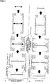
- FIGS. 1 are schematic explanatory diagrams regarding a comparison between a so-called “edging method” being one of rough rolling methods in a conventional manufacturing method of H-shaped steel, and a so-called “split method” being a rough rolling method in the manufacturing method of the H-shaped steel according to the present embodiment.
- the edging method is a method in which grooves for guiding a slab to a caliber center are applied to end portions of the slab at a time of performing rough rolling when manufacturing H-shaped steel from the slab, and hot rolling is performed by using caliber rolls attached to a rough rolling mill.
- the slab heated in a heating furnace is rolled in a width direction, and the end portions of the slab are elongated in a thickness direction of the slab, flange portions are formed.
- intermediate rolling with an intermediate rolling mill finish rolling with a finish rolling mill, and the like are further performed to finely adjust a shape and a size of a product, to thereby manufacture a final H-shaped steel product.
- grooves (splits) whose depth is deeper than that of the grooves in the aforementioned edging method are applied, with a split-creating caliber, to end faces of a slab at a time of performing rough rolling when manufacturing H-shaped steel from the slab.
- rolling and shaping are performed on the applied grooves so as to widen the end portions of the slab formed as divided parts, by using caliber rolls of a shaping caliber formed with projections to widen the grooves.
- a method of forming flange portions by performing such rolling and shaping in a widening manner a plurality of times while changing angles, for example, is the split method.
- intermediate rolling, finish rolling, and the like are further performed to manufacture a final H-shaped steel product.
- the present inventors focused attention on a central segregation portion being a part in which mainly an Mn concentration is high and which exists in a slab, and found out that there is a large difference in a state of aggregation or dispersion of the central segregation portion of the slab between rough rolling performed by the edging method and rough rolling performed by the split method.
- the split method employs a method such that a slab is not rolled in a width direction almost at all and flange portions are widened, so that rough rolling is performed in a state where the central segregation portion is dispersed in the whole of the flange portions and thus is not aggregated in fillet portions. It has become known that by setting a tip angle of projections of a split-creating caliber to an acute angle of 40° or less, in particular, it is possible to suppress the aggregation of the central segregation portion.
- vTrs (Charpy transition temperature) becomes 0°C or less at F/6 at which an average mechanical property of H-shaped steel is exhibited, and a difference between vTrs at F/6 and vTrs at a most embrittled portion at which the toughness becomes the worst due to the central segregation portion can be suppressed to within 40°C, as illustrated in FIG. 2 . It can be inferred that this is because the embrittlement caused by MnS, island martensite (MA) being a hard phase, and upper bainite which exist in the central segregation portion in which mainly the Mn concentration is high, is suppressed.
- MnS island martensite
- MA island martensite
- C facilitates a generation of MA at a fillet portion to lower toughness.
- C can improve strength at a low price, and a complete removal of C leads to an increase in cost in terms of a steelmaking process, so that a C amount is set to 0.01% or more.
- the C amount exceeds 0.25%, MA increases at a position of the fillet portion where a central segregation portion is aggregated to lower the toughness, so that the C amount is limited to 0.25% or less.
- the C amount is preferably set to 0.20% or less, and more preferably set to less than 0.17%.
- Si is a deoxidizing element and it also contributes to the improvement of the strength, but, it is an element which causes generation of MA, similarly to C. If an Si amount exceeds 0.50%, a hard phase is generated, which reduces the toughness of a base material and a weld heat-affected zone, so that the Si amount is limited to 0.50% or less.
- the Si amount is preferably 0.30% or less, more preferably set to 0.20% or less, and still more preferably set to 0.10% or less. However, if Si is not contained, a cost increases in terms of a deoxidizing process, so that Si is contained in an amount of 0.05% or more.
- a central segregation portion of a slab is aggregated in fillet portions.
- Mn is likely to be aggregated in the central segregation portion in particular, and when a concentration of Mn is locally increased, an increase in hardness is facilitated by a formation of MA being an embrittlement phase, an increase in upper bainite being a coarse structure, an increase in MnS, and an increase in hardenability.
- the toughness is lowered significantly.
- Mn in an amount exceeding 2.50% is contained, the toughness of the base material and the weld heat-affected zone is impaired due to an increase in inclusions and the like in the fillet portions.
- the Mn amount is limited to 2.50% or less.
- the Mn amount is preferably set to 2.00% or less, and more preferably set to 1.80% or less.
- Mn is an element effective for making a crystal grain diameter finer, so that Mn is contained in an amount of 0.40% or more.
- P causes a weld crack and a reduction in the toughness due to a solidifying segregation, and thus an amount thereof should be reduced as much as possible.
- the P amount is preferably limited to 0.050% or less, and is more preferably 0.010% or less. Note that a lower limit of P may be 0.001% or more since a cost in the steelmaking process greatly increases if the P amount is lowered to less than 0.001%.
- S forms MnS in a central segregation portion formed by the solidifying segregation, and it causes not only the weld crack and the reduction in the toughness but also a hydrogen crack and the like, and thus an amount thereof should be reduced as much as possible.
- the S amount is preferably limited to 0.050% or less, and is more preferably 0.010% or less. Note that a lower limit of S may be 0.001% or more since a cost in the steelmaking process greatly increases if the S amount is lowered to less than 0.001%.
- optional additive elements it is also possible to make one or two or more of Cu, Ni, Cr, V, Mo, Nb, Ti, Al, and N to be contained as optional additive elements for the purpose of improving the strength and the toughness. Note that since the optional additive elements are not necessarily added, a lower limit value of a content of each optional additive element is 0%.
- Cu is an element which contributes to the improvement of the strength. However, if a Cu amount exceeds 0.70%, the strength is excessively increased to lower the toughness, so that the Cu amount is limited to 0.70% or less.
- the Cu amount is preferably set to 0.50% or less, more preferably set to 0.30% or less, and still more preferably set to 0.10% or less.
- a lower limit of the Cu amount is preferably 0.01%.
- Ni is an element which is quite effective for increasing the strength and the toughness. However, since Ni is an expensive element, in order to suppress an increase in an alloying cost, an Ni amount is limited to 0.70% or less, preferably set to 0.50% or less, more preferably set to 0.30% or less, and still more preferably set to 0.10% or less. The Ni amount is preferably 0.01% or more, and more preferably set to 0.02% or more.
- Cr is also an element which contributes to the improvement of the strength. However, if Cr in an amount exceeding 0.50% is added, a carbide is generated, which may impair the toughness, so that the Cr amount is limited to 0.50% or less, and preferably set to 0.30% or less. A lower limit of the Cr amount is preferably set to 0.01%.
- V is an element which forms a nitride (VN), and it may be contained in an amount of 0.01% or more for increasing the strength of the base material.
- the V amount is preferably set to 0.02% or more, and more preferably set to 0.03% or more.
- an upper limit of the V amount is limited to 0.12%, and preferably limited to 0.08%.
- Mo is an element which increases the hardenability to contribute to the improvement of the strength.
- Mo in an amount exceeding 0.30% is added, a precipitation of Mo carbide (Mo 2 C) or a generation of MA at the fillet portion is facilitated, and the toughness of the weld heat-affected zone in particular sometimes deteriorates, so that the Mo amount is limited to 0.30% or less, and preferably set to 0.15% or less.
- a lower limit of the Mo amount is preferably 0.01%.
- Nb is an element which makes ferrite finer to improve the toughness. However, if Nb in an amount exceeding 0.08% is added, a ferrite transformation is excessively suppressed to facilitate the generation of MA, so that the Nb amount is limited to 0.08% or less, preferably set to 0.05% or less, and more preferably set to 0.03% or less.
- Ti is an element which forms TiN, and if a Ti amount exceeds 0.05%, TiN becomes coarse and becomes a starting point of a brittle fracture, so that the Ti amount is limited to 0.05% or less.
- the Ti amount is preferably set to 0.03% or less, and more preferably set to 0.02% or less.
- a lower limit of the Ti amount may be 0%, but, a fine TiN makes a contribution to make a structure finer, so that Ti in an amount of 0.005% or more may be contained.
- Al is a deoxidizing element, and if an Al amount exceeds 0.07%, the toughness of the base material and the weld heat-affected zone is lowered by inclusions, so that the Al amount is limited to 0.07% or less.
- the Al amount is preferably 0.05% or less, more preferably set to 0.04% or less, and still more preferably set to 0.03% or less.
- a lower limit of the Al amount is not defined, and may be 0%, but, since Al is a useful deoxidizing element, Al in an amount of 0.01% or more may be contained.
- N is an element which lowers the toughness of the base material and the weld heat-affected zone. If an N amount exceeds 0.020%, low-temperature toughness is impaired by solid-solution N and a formation of coarse precipitates, so that the N amount is limited to 0.020% or less.
- the N amount is preferably set to 0.010% or less, and more preferably set to 0.007% or less. On the other hand, if the N amount is tried to be reduced to less than 0.002%, a cost in the steelmaking process is increased, so that the N amount may be 0.002% or more. From a viewpoint of cost, the N amount may be 0.003% or more.
- one or two of REM and Ca may be contained as optional additive elements for the purpose of controlling a form of inclusions.
- REM and Ca are deoxidizing elements, and they also contribute to control of a form of a sulfide, so that they may be added.
- oxides of REM and Ca are easily floated in molten steel, an amount of REM and an amount of Ca contained in the steel are limited to 0.010% or less and 0.0050% or less, respectively.
- a lower limit of each of the REM amount and the Ca amount is preferably set to 0.0005%.
- FIG. 3 is a schematic explanatory diagram illustrating positions where a mechanical test and an observation of a metal structure are performed.
- FIG. 3 explanation will be made on results obtained by performing verification on a metal structure and properties mainly at the positions illustrated in FIG. 3 .
- a position of 1/6 in a flange width direction from an end face in the flange width direction in a flange and 1/4 in a flange thickness direction from a face of the flange positioned on a side opposite to that of a web (namely, a lateral surface), is in the middle of a flange end portion where a temperature is likely to lower when performing hot rolling and a flange center portion where the temperature is unlikely to lower. Further, there is no chance that the central segregation portion is observed at this part. Therefore, it can be considered that at the position, average chemical components and mechanical properties of H-shaped steel are exhibited based on a temperature distribution.
- the position is represented as "F/6-t/4" by using a flange width F and a flange thickness t.
- the H-shaped steel according to the present embodiment suppresses a material variation in the flanges. For this reason, the observation of the metal structure and the measurement of the mechanical properties (strength and Charpy absorbed energy) of the H-shaped steel are performed by collecting a sample piece from each of a position of a most embrittled portion in the vicinity of F/2-3t/4 and a position of F/6-t/4 of the H-shaped steel illustrated in FIG. 3 .
- the position of the most embrittled portion is not fixed with respect a horizontal direction of the drawing, namely, the flange width direction, depending on a situation when performing rough rolling of flanges. Accordingly, a part where the central segregation portion is aggregated is made to appear by a nital etchant, and then a part at which a straight line indicating a position of 3/4 in the flange thickness direction from a face of the flange positioned on a side opposite to that of a web (3t/4) and the part where the above-described central segregation portion is aggregated intersect is set as a position of the most embrittled portion. From the most embrittled portion whose position is specified, the sample piece is collected, and the observation of the metal structure and the measurement of the mechanical properties are carried out.
- the metal structure of the rolled H-shaped steel of the present invention is evaluated by an optical microscope, a scanning electron microscope (SEM), and an electron probe micro analyzer (EPMA).
- SEM scanning electron microscope
- EPMA electron probe micro analyzer
- a visual field of 10 mm ⁇ 10 mm in which the most embrittled portion illustrated in FIG. 3 is set as a center is identified.
- an electrolytic polishing is performed, and then an Mn concentration at the set position of the most embrittled portion is measured under conditions of an acceleration voltage of 20 kV, a beam shape of a band shape with a length of 20 ⁇ m, and a step of 20 ⁇ m.
- an average value of 12500 points to be values of top 5% or more (this is referred to as a "top 5% average value”) is determined, and set as an Mn concentration (CMn-max) at the most embrittled portion.
- the sample is collected from the position of F/6-t/4, and a value of an Mn concentration determined by analyzing chemical components of the sample according to JIS G0404 (2014 edition), is set as an Mn concentration (CMn) at the position of F/6-t/4.
- CMn-max a value of dividing (CMn-max) by (CMn)
- CMn a value of dividing (CMn-max) by (CMn)
- a target value of the strength of the rolled H-shaped steel according to the present invention is set based on the steel material standard EN10225 adopted in the European region. It is desirable that a yield point (YP) or 0.2% yield strength and a tensile strength (TS) measured at room temperature by using the sample piece collected from the position of F/6-t/4 are 325 MPa or more and 450 MPa or more, respectively.
- a target value of the toughness is set to ⁇ vTrs ⁇ 40°C.
- FIG. 2 is a diagram illustrating a correlation between a segregation degree and a Charpy transition temperature difference ⁇ vTrs in H-shaped steel.
- the segregation degree in FIG. 2 indicates a concentration ratio of Mn between the most embrittled portion and the position of F/6-t/4 described above while referring to FIG. 3 .
- the Charpy transition temperature difference ⁇ vTrs between the most embrittled portion and the position of F/6-t/4 is 40°C or less.
- the aggregation of the central segregation portion is suppressed, and it is possible to obtain rolled H-shaped steel with better uniformity in a cross section of flanges, when compared to a conventional product.
- vTrs at the position of F/6-t/4 is 0°C or less.
- the segregation degree illustrated in FIG. 2 is preferably 1.6 or less. It is more preferable that the segregation degree is 1.5 or less, since as the segregation degree is lowered, the aggregation of the central segregation portion is further suppressed and the embrittlement characteristic becomes better. Further, there is no chance that the segregation degree becomes less than 1.0 in terms of a characteristic of numeric value, and the segregation degree is preferably 1.0 or more or 1.1 or more, for example.
- a manufacturing method of the H-shaped steel according to the present embodiment will be described.
- a rectangular steel billet excellent in productivity is heated and hot rolling composed of a rough rolling step, an intermediate rolling step, and a finish rolling step is performed through steps illustrated in FIG. 4 , and accelerated cooling is performed by a water cooler, to thereby manufacture the H-shape steel.
- the rough rolling is performed by the split method illustrated in FIG. 1(b) .
- a steelmaking step an upstream side of a heating furnace in FIG. 4
- chemical components of molten steel are adjusted, and then casting is performed, thereby obtaining a rectangular steel billet (which is also referred to as so-called "slab").
- the casting is preferably continuous casting from a viewpoint of productivity.
- a thickness of the steel billet is preferably set to 200 mm or more from a viewpoint of productivity, and is preferably 350 mm or less when taking a reduction in the segregation, homogeneity of a heating temperature in the hot rolling, and the like into consideration.
- the steel billet is heated by using the heating furnace, and the hot rolling is performed.
- the rough rolling based on the split method illustrated in FIG. 1(b) is performed by using a rough rolling mill.
- the intermediate rolling is performed by using an intermediate universal rolling mill (an intermediate rolling mill) and water coolers.
- the finish rolling is performed by using a finish rolling mill, and the hot rolling is terminated.
- Heating temperature of steel billet 1100 to 1350°C
- the heating temperature of the steel billet is set to 1100 to 1350°C. If the heating temperature is low, a deformation resistance becomes high, so that the heating temperature of the steel billet is set to 1100°C or more for securing a shaping property in the hot rolling. On the other hand, if the heating temperature of the steel billet exceeds 1350°C, there is a chance that an oxide on a surface of the steel billet being a material is smelted to damage an inside of the heating furnace. In order to cause sufficient solid-solution of the element such as Nb which forms a precipitate, a lower limit of the heating temperature of the steel billet is preferably set to 1150°C or more.
- the heating temperature of the steel billet is preferably set to 1200°C or more.
- an upper limit of the heating temperature of the steel billet it is preferable to set an upper limit of the heating temperature of the steel billet to 1300°C or less.
- a lower limit of the split length H is set to satisfy 0.5F - 0.5T or more with respect to the thickness T of the steel billet having the rectangular cross section and the flange width F of the rolled H-shaped steel formed by the finish rolling step. This is for suppressing a reduction amount in a caliber with an obtuse angle by which the aggregation of the central segregation portion is likely to occur, by performing the rolling and shaping based on the split method until when the flange width after the rough rolling becomes about the same as a flange width of a product.
- an upper limit of the split length H is not particularly provided, it is desirably 0.8F - 0.5T or less, since if the split length H exceeds 0.8F - 0.5T, excessive edging rolling becomes required when performing the intermediate rolling, which deteriorates the productivity.
- the caliber tip angle (the tip angle of the projection of the inner periphery of the caliber) illustrated in FIG. 1(b) and FIG. 5 is only required to be set to an angle which is acute enough to create a split, and an upper limit thereof may be set to 40°, for example. This is because if the caliber tip angle exceeds 40°, the central segregation portion of the slab is not dispersed in the flanges, and is aggregated in the fillet portions, similarly to the edging rolling illustrated in FIG. 1(a) . By setting the caliber tip angle to 40° or less, the central segregation portion is dispersed without being aggregated in the flanges when performing the rolling with the split-creating caliber as illustrated in the split method in FIG. 1(b) , and it becomes possible to suppress the reduction in the toughness at the fillet portions.
- a lower limit of the caliber tip angle is not particularly provided, it is preferably 25° or more, since if the caliber tip angle is less than 25°, there is a possibility that rolls are broken when performing the rolling.
- the central segregation portion of the slab is not divided into right and left flanges in an I-posture as illustrated in FIG. 1(b) , but is dispersed in either the left flange or the right flange.
- a central segregation portion is dispersed in a flange portion, and remains in a region 15 mm or more apart from a vicinity of a center of the flange width toward one end face or both end faces in the flange width direction and within 2 mm from a flange surface layer in the thickness direction (in the flange thickness direction from a flange face positioned on a side opposite to that of a web), in the flange.
- the central segregation portion dispersed in the flange portion remains in the region along the predetermined length.
- the central segregation portion dispersed in the vicinity of the surface layer can be made to appear by the identification using the nital etchant described above.
- a top 5% average concentration of Mn in the central segregation portion dispersed in the vicinity of the surface layer is set to (CMn-surface), and a segregation degree at this position (CMn-surface) / (CMn) is desirably not less than 1.1 nor more than 1.6.
- the segregation degree at the flange surface layer tends to be higher when compared to the edging method. If the segregation degree is 1.1 or more, there is a merit such that a crack on the surface can be visually checked, and it becomes easy to perform the inspection, and further, it also becomes possible to trace a plurality of products to be manufactured as respective individuals, based on the crack on the surface.
- the segregation degree exceeds 1.6, a large number of cracks are likely to occur on the flange surface, so that the segregation degree is desirably not less than 1.1 nor more than 1.6.
- the way of determining the top 5% average concentration regarding (CMn-surface) is according to the way of determining the top 5% average concentration regarding (CMn-max) described above.
- the ways of determining the numeric values are basically the same in which only the positions of collecting the samples are different.
- the controlled rolling is a manufacturing method of controlling a rolling temperature and a reduction ratio.
- the interpass water-cooled rolling the water cooling is performed between rolling passes, to thereby perform rolling while providing a temperature difference between a surface layer portion and an inner portion of the flange.
- the interpass water-cooled rolling is a manufacturing method in which, for example, a flange surface temperature is lowered to 700°C or less through the water cooling performed between the rolling passes, and then rolling is performed in a recuperation process.
- the interpass water-cooled rolling When the interpass water-cooled rolling is performed, it is preferable to perform water cooling between the rolling passes by using water coolers provided in front of and behind the intermediate universal rolling mill, and it is preferable that spray cooling of flange lateral surfaces with the use of the water cooler, and reverse rolling are repeatedly conducted.
- the interpass water-cooled rolling even if a reduction ratio is small, it is possible to introduce a working strain into an inside of the sheet in the thickness direction. Further, by reducing the rolling temperature in a short period of time by the water cooling, the productivity is also improved.
- the rolled H-shaped steel manufactured by the manufacturing method of the H-shaped steel according to the present embodiment described above it is possible to complete the rolling and shaping by dispersing the central segregation portion which exists in the slab before being subjected to the rolling and shaping, without making the central segregation portion aggregate in the fillet portions.
- the rolled H-shaped steel is manufactured in which ⁇ vTrs is 40°C or less in the flanges after performing the rolling and shaping, and the segregation degree thereof becomes 1.6 or less (refer to FIG. 2 ).
- the central segregation portion dispersed in the flange remains in the region 15 mm or more apart from the center of the flange width toward one end face or both end faces in the flange width direction and within 2 mm in the flange thickness direction from the face positioned on the side opposite to that of the web, in the flange, but, the central segregation portion is not aggregated, so that it can be estimated that there is no influence almost at all with respect to the toughness and the embrittlement characteristic.
- various examinations, experiments, and so on have been conventionally required to examine the state of the inside of the flange, in the H-shaped steel product according to the present embodiment, it is possible to visually check the flange face positioned on the side opposite to that of the web.
- samples were collected from rolled H-shaped steels each manufactured by satisfying the chemical composition and the manufacturing condition described in the above-described embodiment, and the samples were subjected to a chemical analysis.
- samples were collected from rolled H-shaped steels each of which did not satisfy either the chemical composition or the manufacturing condition described in the above-described embodiment, and the samples were subjected to a similar chemical analysis.
- steels having chemical compositions (unit: mass%) shown in Table 1 were smelted, and steel billets each having a thickness of 250 to 300 mm were manufactured through continuous casting.
- the steels were smelted in a converter, subjected to primary deoxidation, components were adjusted by adding an alloy thereto, and according to need, vacuum degassing treatment was conducted.
- the obtained steel billets were subjected to hot rolling under manufacturing conditions shown in Table 2.
- rough rolling was performed, and subsequently, by using an intermediate universal rolling mill and water coolers provided in front of and behind the intermediate universal rolling mill, spray cooling of flange lateral surfaces, reverse rolling, and water cooling after the rolling were conducted according to need.
- TEMPERATURE (°C) CALIBER TIP ANGLE (°) SPLIT LENGTH (mm) SLAB THICKNESS (mm) FLANGE WIDTH (mm) 0.5F-0.5T 1 1350 40 150 250 500 125 2 1350 40 100 250 400 75 3 1300 30 280 250 700 225 4 1300 30 100 300 400 50 5 1250 40 200 300 500 100 6 1250 40 200 300 600 150 7 1200 40 300 300 700 200 8 1200 40 120 300 500 100 9 1100 25 160 300 600 150 10 1100 25 210 300 700 200 11 1100 40 170 300 600 150 12 1200 40 250 250 500 125 13 1200 40 300 250 600 175 28 1250 40 200 250 500 125
- test pieces in which a rolling direction was set to a longitudinal direction were collected to measure the mechanical properties.
- the yield point (YP), the tensile strength (TS), and vTrs were measured.
- a tensile test was conducted based on JIS Z 2241 (2011 edition), and a Charpy impact test was conducted based on JIS Z 2242 (2005 edition).
- the central segregation remained within 2 mm from a surface layer 15 mm or more apart from a center of the flange width toward at least one end face in the flange width direction, and as the Mn concentration of the surface layer portion, (CMn-surface) was measured and calculated through the EPMA regarding a region including no central segregation parallel to the flange thickness direction and positioned at 10 mm below the flange surface layer in the thickness direction (refer to FIG. 3 ).
- the yield point (YP) or the 0.2% yield strength at room temperature is 335 MPa or more
- the tensile strenght (TS) at room temperature is 450 MPa or more
- ⁇ vTrs is 40°C or less.
- the strength at room temperature is within the target range, and ⁇ vTrs satisfies the target value of 40°C or less.
- the segregation degree of Mn was 1.6 or less.
- the segregation degree of Mn is desirably 1.5 or less, and more desirably 1.4 or less.
- test pieces in which a rolling direction was set to a longitudinal direction were collected to measure the mechanical properties, similarly to the above-described examples.
- the mechanical properties the yield point (YP), the tensile strength (TS), and vTrs were measured.
- samples were collected from the respective positions of the most embrittled portion, the surface layer portion, and F/6-t/4, and (CMn-max) and (CMn-surface) were measured and calculated through the EPMA, and (CMn) was measured and calculated through the method described in JIS G0404 (2014 edition), similarly to the above-described examples.
- the present invention is applicable to rolled H-shaped steel manufactured by performing hot rolling on a steel billet, and a manufacturing method thereof.
Landscapes
- Chemical & Material Sciences (AREA)
- Engineering & Computer Science (AREA)
- Mechanical Engineering (AREA)
- Materials Engineering (AREA)
- Metallurgy (AREA)
- Organic Chemistry (AREA)
- Crystallography & Structural Chemistry (AREA)
- Physics & Mathematics (AREA)
- Thermal Sciences (AREA)
- Heat Treatment Of Steel (AREA)
- Metal Rolling (AREA)
- Rod-Shaped Construction Members (AREA)
Abstract
Description
- This application is based upon and claims the benefit of priority of the prior Japanese Patent Application No.
2016-166535 - The present invention relates to rolled H-shaped steel manufactured by performing hot rolling on a steel billet, and a manufacturing method thereof.
- Conventionally, H-shaped steel has been widely used as a material of a construction structure, a civil engineering structure, an offshore structure, and the like, and H-shaped steels having various cross sections have been used. In particular, H-shaped steel using a slab having a rectangular cross section and obtained through continuous casting with high productivity as a steel material and manufactured by hot rolling, requires a low manufacturing cost, and is used in various fields. Conventionally, H-shaped steel manufactured from a slab has been manufactured by an edging method illustrated in
FIG. 1(a) . The edging method is a rolling method in which grooves for guiding a steel material to a caliber center of rolls are first formed on end portions of a slab, rolling is performed in a width direction of the slab, and the end portions of the slab are elongated in a thickness direction of the slab, to thereby form flange portions. In a central segregation portion formed when casting the slab, alloy elements including Mn are concentrated. By performing the rolling with the edging method, the central segregation portion is further aggregated at a part where a web and a flange intersect, which is a so-called "fillet portion", which sometimes exerts an adverse effect on toughness. - In view of such problems, in order to solve a macrosegregation (the aggregation of the central segregation portion), it is effective to perform heating at a high temperature for a certain period of time to diffuse Mn and the like, and there has been proposed a method in which heat treatment is performed on a steel billet before being subjected to hot rolling (refer to Patent Document 1, for example). Further, in order to facilitate the diffusion, it is effective to perform rolling to apply a strain, and then perform retention at a high temperature, and there has been proposed a method in which a steel billet is subjected to rough rolling, and then reheated before intermediate rolling (refer to Patent Documents 2 and 3, for example).
- Further, there has been proposed a method of solving the macrosegregation other than the heat treatment (refer to
Patent Documents 4 and 5, for example).Patent Document 4 discloses a method in which reduction is performed before solidification is completed in continuous casting. Meanwhile, Patent Document 5 discloses a method in which a caliber for performing edging in a slab width direction of a rough rolling mill is formed into a box caliber with a flat bottom, which is called as a wedge method. -
- [Patent Document 1] Japanese Laid-open Patent Publication No.
2012-180584 - [Patent Document 2] Japanese Laid-open Patent Publication No.
H6-122921 - [Patent Document 3] Japanese Laid-open Patent Publication No.
H6-122922 - [Patent Document 4] Japanese Laid-open Patent Publication No.
H5-305395 - [Patent Document 5] Japanese Laid-open Patent Publication No.
H7-88502 - As described above, various countermeasures have been conventionally proposed in order to suppress the reduction in the toughness of the fillet portions of the rolled H-shaped steel caused by the macrosegregation. However, each countermeasure has a problem that the productivity is impaired with respect to the edging method being the conventional technique.
- Accordingly, in view of such actual circumstance, the present invention has an object to provide rolled H-shaped steel and a manufacturing method thereof in which a macrosegregation of fillet portions is reduced without impairing the productivity with respect to the edging method being the conventional technique.
- The present invention is characterized in that it includes a step of creating splits by using a shaping caliber formed with projections which create splits vertically with respect to a width direction of a material to be rolled, and performing sequential bending by setting the splits as starting points. According to the step as described above, a central segregation portion is dispersed in the whole of flanges at a time of forming the flanges from a slab, resulting in that an aggregation of a central segregation portion at fillet portions can be suppressed without impairing the productivity.
- The gist of the present invention is as follows.
- [1] Rolled H-shaped steel is characterized in that it includes a chemical composition comprising : in mass%, C: 0.01 to 0.25%; Si: 0.05% to 0.50%; Mn: 0.40 to 2.50%; P: 0.050% or less; S: 0.050% or less; N: 0.020% or less; Cu: 0.70% or less; Ni: 0.70% or less; Cr: 0.50% or less; V: 0.12% or less; Mo: 0.30% or less; Nb: 0.08% or less; Ti: 0.05% or less; Al: 0.07% or less; REM: 0.010% or less; Ca: 0.0050% or less; and the balance: Fe and inevitable impurities, in which: a top 5% average value of Mn concentrations in a most embrittled portion in a flange is 1.6 times or less an Mn concentration at a position of 1/6 in a flange width direction from an end face in the flange width direction and 1/4 in a flange thickness direction from a face of a flange positioned on a side opposite to that of a web; and a top 5% average value of Mn concentrations in a central segregation portion dispersed in a region 15 mm or more apart from a center of the flange width toward one end face or both end faces in the flange width direction and within 2 mm from a flange surface layer in the thickness direction is not less than 1.1 times nor more than 1.6 times the Mn concentration at the position of 1/6 in the flange width direction from the end face in the flange width direction and 1/4 in the flange thickness direction from the face of the flange positioned on the side opposite to that of the web.
- [2] A manufacturing method of rolled H-shaped steel being a manufacturing method of manufacturing the rolled H-shaped steel described in [1] is characterized in that it includes heating a steel billet having a rectangular cross section to 1100 to 1350°C, and sequentially performing a rough rolling step, an intermediate rolling step, and a finish rolling step, in which: to a rolling mill which performs the rough rolling step, a plurality of calibers of three or more to shape a material to be rolled are provided; at least one of the plurality of calibers is a split-creating caliber provided to a pair of upper and lower rolls and formed with projections which create splits vertically with respect to a width direction of the material to be rolled; and in a subsequent stage of the split-creating caliber, a shaping caliber which sequentially bends divided parts formed by the split-creating caliber is provided.
- [3] The manufacturing method of the rolled H-shaped steel described in [2] is characterized in that a tip angle of the projections formed in the split-creating caliber is 40° or less.
- [4] The manufacturing method of the rolled H-shaped steel described in [2] or [3] is characterized in that a length H of the split created by the projection, a thickness T of the steel billet having the rectangular cross section, and a width F of a flange of the rolled H-shaped steel formed by the finish rolling step satisfy the following expression (1).

- According to the present invention, it becomes possible to obtain H-shaped steel excellent in toughness of fillet portions through simple steps without performing special heat treatment such as preliminary heating, and reheating, temperature retention, or the like after rolling. Therefore, it becomes possible to further improve reliability of a steel structure which uses rolled H-shaped steel as a member without impairing an economic efficiency, and as described above, the present invention contributes to the industry quite significantly.
-
-
FIGS. 1 are schematic explanatory diagrams regarding a comparison between an "edging method" and a "split method". -
FIG. 2 is a diagram illustrating a correlation between a segregation degree and a Charpy transition temperature difference ΔvTrs. -
FIG. 3 is a schematic explanatory diagram illustrating positions where a mechanical test and an observation of a metal structure are performed. -
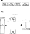
FIG. 4 is a schematic explanatory diagram illustrating manufacturing steps of H-shaped steel according to an embodiment of the present invention. -
FIG. 5 is a schematic explanatory diagram illustrating rolls used for rough rolling and a shape of a material to be rolled. - Hereinafter, an embodiment of the present invention will be described while referring to the drawings. Note that in the present specification and the drawings, components having substantially the same functional configurations are denoted by the same reference numerals to omit overlapped explanation.
- The present inventors obtained a finding that, if splits are created when forming flange portions and the flange portions are bent to be manufactured, a segregation is dispersed in the whole of the flanges, resulting in that an aggregation of the segregation at fillet portions is improved. First, this finding will be briefly described.
- Note that a manufacturing method of H-shaped steel according to the present embodiment in which flange portions are bent to perform rolling and shaping, is referred to as a "split method" in the present specification.
- First, an outline of the aforementioned "split method" will be briefly described while referring to
FIGS. 1. FIGS. 1 are schematic explanatory diagrams regarding a comparison between a so-called "edging method" being one of rough rolling methods in a conventional manufacturing method of H-shaped steel, and a so-called "split method" being a rough rolling method in the manufacturing method of the H-shaped steel according to the present embodiment. - As illustrated in
FIG. 1(a) , the edging method is a method in which grooves for guiding a slab to a caliber center are applied to end portions of the slab at a time of performing rough rolling when manufacturing H-shaped steel from the slab, and hot rolling is performed by using caliber rolls attached to a rough rolling mill. When the slab heated in a heating furnace is rolled in a width direction, and the end portions of the slab are elongated in a thickness direction of the slab, flange portions are formed. On the material to be rolled formed with the flange portions as described above, intermediate rolling with an intermediate rolling mill, finish rolling with a finish rolling mill, and the like are further performed to finely adjust a shape and a size of a product, to thereby manufacture a final H-shaped steel product. - On the other hand, as illustrated in
FIG. 1(b) , in the split method, grooves (splits) whose depth is deeper than that of the grooves in the aforementioned edging method are applied, with a split-creating caliber, to end faces of a slab at a time of performing rough rolling when manufacturing H-shaped steel from the slab. Subsequently, rolling and shaping are performed on the applied grooves so as to widen the end portions of the slab formed as divided parts, by using caliber rolls of a shaping caliber formed with projections to widen the grooves. A method of forming flange portions by performing such rolling and shaping in a widening manner a plurality of times while changing angles, for example, is the split method. On the material to be rolled formed with the flange portions as described above, intermediate rolling, finish rolling, and the like are further performed to manufacture a final H-shaped steel product. - When comparing the edging method with the split method illustrated in
FIGS. 1 , the present inventors focused attention on a central segregation portion being a part in which mainly an Mn concentration is high and which exists in a slab, and found out that there is a large difference in a state of aggregation or dispersion of the central segregation portion of the slab between rough rolling performed by the edging method and rough rolling performed by the split method. - Specifically, as illustrated in
FIG. 1(a) , in the edging method, it is known that the central segregation portion is aggregated in fillet portions when a slab is rolled in a width direction by caliber rolls. On the other hand, as illustrated inFIG. 1(b) , the split method employs a method such that a slab is not rolled in a width direction almost at all and flange portions are widened, so that rough rolling is performed in a state where the central segregation portion is dispersed in the whole of the flange portions and thus is not aggregated in fillet portions. It has become known that by setting a tip angle of projections of a split-creating caliber to an acute angle of 40° or less, in particular, it is possible to suppress the aggregation of the central segregation portion. - Further, the present inventors found out that, by using the split method, vTrs (Charpy transition temperature) becomes 0°C or less at F/6 at which an average mechanical property of H-shaped steel is exhibited, and a difference between vTrs at F/6 and vTrs at a most embrittled portion at which the toughness becomes the worst due to the central segregation portion can be suppressed to within 40°C, as illustrated in
FIG. 2 . It can be inferred that this is because the embrittlement caused by MnS, island martensite (MA) being a hard phase, and upper bainite which exist in the central segregation portion in which mainly the Mn concentration is high, is suppressed. - Hereinbelow, rolled H-shaped steel according to the present embodiment and a manufacturing method thereof based on the findings as described above will be described in detail. Note that in the description hereinbelow, the description of "%" regarding a component means "mass%" unless otherwise specified.
- First, a composition of components (a chemical composition) of H-shaped steel will be described.
- C facilitates a generation of MA at a fillet portion to lower toughness. However, C can improve strength at a low price, and a complete removal of C leads to an increase in cost in terms of a steelmaking process, so that a C amount is set to 0.01% or more. On the other hand, if the C amount exceeds 0.25%, MA increases at a position of the fillet portion where a central segregation portion is aggregated to lower the toughness, so that the C amount is limited to 0.25% or less. The C amount is preferably set to 0.20% or less, and more preferably set to less than 0.17%.
- Si is a deoxidizing element and it also contributes to the improvement of the strength, but, it is an element which causes generation of MA, similarly to C. If an Si amount exceeds 0.50%, a hard phase is generated, which reduces the toughness of a base material and a weld heat-affected zone, so that the Si amount is limited to 0.50% or less. The Si amount is preferably 0.30% or less, more preferably set to 0.20% or less, and still more preferably set to 0.10% or less. However, if Si is not contained, a cost increases in terms of a deoxidizing process, so that Si is contained in an amount of 0.05% or more.
- In H-shaped steel manufactured by the edging method, a central segregation portion of a slab is aggregated in fillet portions. Mn is likely to be aggregated in the central segregation portion in particular, and when a concentration of Mn is locally increased, an increase in hardness is facilitated by a formation of MA being an embrittlement phase, an increase in upper bainite being a coarse structure, an increase in MnS, and an increase in hardenability. As a result of this, the toughness is lowered significantly. In particular, if Mn in an amount exceeding 2.50% is contained, the toughness of the base material and the weld heat-affected zone is impaired due to an increase in inclusions and the like in the fillet portions. For this reason, the Mn amount is limited to 2.50% or less. The Mn amount is preferably set to 2.00% or less, and more preferably set to 1.80% or less. On the other hand, Mn is an element effective for making a crystal grain diameter finer, so that Mn is contained in an amount of 0.40% or more.
- P causes a weld crack and a reduction in the toughness due to a solidifying segregation, and thus an amount thereof should be reduced as much as possible. The P amount is preferably limited to 0.050% or less, and is more preferably 0.010% or less. Note that a lower limit of P may be 0.001% or more since a cost in the steelmaking process greatly increases if the P amount is lowered to less than 0.001%.
- S forms MnS in a central segregation portion formed by the solidifying segregation, and it causes not only the weld crack and the reduction in the toughness but also a hydrogen crack and the like, and thus an amount thereof should be reduced as much as possible. The S amount is preferably limited to 0.050% or less, and is more preferably 0.010% or less. Note that a lower limit of S may be 0.001% or more since a cost in the steelmaking process greatly increases if the S amount is lowered to less than 0.001%.
- In addition, it is also possible to make one or two or more of Cu, Ni, Cr, V, Mo, Nb, Ti, Al, and N to be contained as optional additive elements for the purpose of improving the strength and the toughness. Note that since the optional additive elements are not necessarily added, a lower limit value of a content of each optional additive element is 0%.
- Cu is an element which contributes to the improvement of the strength. However, if a Cu amount exceeds 0.70%, the strength is excessively increased to lower the toughness, so that the Cu amount is limited to 0.70% or less. The Cu amount is preferably set to 0.50% or less, more preferably set to 0.30% or less, and still more preferably set to 0.10% or less. A lower limit of the Cu amount is preferably 0.01%.
- Ni is an element which is quite effective for increasing the strength and the toughness. However, since Ni is an expensive element, in order to suppress an increase in an alloying cost, an Ni amount is limited to 0.70% or less, preferably set to 0.50% or less, more preferably set to 0.30% or less, and still more preferably set to 0.10% or less. The Ni amount is preferably 0.01% or more, and more preferably set to 0.02% or more.
- Cr is also an element which contributes to the improvement of the strength. However, if Cr in an amount exceeding 0.50% is added, a carbide is generated, which may impair the toughness, so that the Cr amount is limited to 0.50% or less, and preferably set to 0.30% or less. A lower limit of the Cr amount is preferably set to 0.01%.
- V is an element which forms a nitride (VN), and it may be contained in an amount of 0.01% or more for increasing the strength of the base material. The V amount is preferably set to 0.02% or more, and more preferably set to 0.03% or more. On the other hand, since V is an expensive element, an upper limit of the V amount is limited to 0.12%, and preferably limited to 0.08%.
- Mo is an element which increases the hardenability to contribute to the improvement of the strength. However, if Mo in an amount exceeding 0.30% is added, a precipitation of Mo carbide (Mo2C) or a generation of MA at the fillet portion is facilitated, and the toughness of the weld heat-affected zone in particular sometimes deteriorates, so that the Mo amount is limited to 0.30% or less, and preferably set to 0.15% or less. A lower limit of the Mo amount is preferably 0.01%.
- Nb is an element which makes ferrite finer to improve the toughness. However, if Nb in an amount exceeding 0.08% is added, a ferrite transformation is excessively suppressed to facilitate the generation of MA, so that the Nb amount is limited to 0.08% or less, preferably set to 0.05% or less, and more preferably set to 0.03% or less.
- Ti is an element which forms TiN, and if a Ti amount exceeds 0.05%, TiN becomes coarse and becomes a starting point of a brittle fracture, so that the Ti amount is limited to 0.05% or less. The Ti amount is preferably set to 0.03% or less, and more preferably set to 0.02% or less. A lower limit of the Ti amount may be 0%, but, a fine TiN makes a contribution to make a structure finer, so that Ti in an amount of 0.005% or more may be contained.
- Al is a deoxidizing element, and if an Al amount exceeds 0.07%, the toughness of the base material and the weld heat-affected zone is lowered by inclusions, so that the Al amount is limited to 0.07% or less. The Al amount is preferably 0.05% or less, more preferably set to 0.04% or less, and still more preferably set to 0.03% or less. A lower limit of the Al amount is not defined, and may be 0%, but, since Al is a useful deoxidizing element, Al in an amount of 0.01% or more may be contained.
- N is an element which lowers the toughness of the base material and the weld heat-affected zone. If an N amount exceeds 0.020%, low-temperature toughness is impaired by solid-solution N and a formation of coarse precipitates, so that the N amount is limited to 0.020% or less. The N amount is preferably set to 0.010% or less, and more preferably set to 0.007% or less. On the other hand, if the N amount is tried to be reduced to less than 0.002%, a cost in the steelmaking process is increased, so that the N amount may be 0.002% or more. From a viewpoint of cost, the N amount may be 0.003% or more.
- Besides, one or two of REM and Ca may be contained as optional additive elements for the purpose of controlling a form of inclusions.
- REM and Ca are deoxidizing elements, and they also contribute to control of a form of a sulfide, so that they may be added. However, since oxides of REM and Ca are easily floated in molten steel, an amount of REM and an amount of Ca contained in the steel are limited to 0.010% or less and 0.0050% or less, respectively. A lower limit of each of the REM amount and the Ca amount is preferably set to 0.0005%.
- Next, a metal structure and properties of the rolled H-shaped steel according to the present invention will be described.
FIG. 3 is a schematic explanatory diagram illustrating positions where a mechanical test and an observation of a metal structure are performed. Hereinafter, explanation will be made on results obtained by performing verification on a metal structure and properties mainly at the positions illustrated inFIG. 3 . - As illustrated in
FIG. 3 , a position of 1/6 in a flange width direction from an end face in the flange width direction in a flange and 1/4 in a flange thickness direction from a face of the flange positioned on a side opposite to that of a web (namely, a lateral surface), is in the middle of a flange end portion where a temperature is likely to lower when performing hot rolling and a flange center portion where the temperature is unlikely to lower. Further, there is no chance that the central segregation portion is observed at this part. Therefore, it can be considered that at the position, average chemical components and mechanical properties of H-shaped steel are exhibited based on a temperature distribution. - Note that in the present specification, the position is represented as "F/6-t/4" by using a flange width F and a flange thickness t.
- The H-shaped steel according to the present embodiment suppresses a material variation in the flanges. For this reason, the observation of the metal structure and the measurement of the mechanical properties (strength and Charpy absorbed energy) of the H-shaped steel are performed by collecting a sample piece from each of a position of a most embrittled portion in the vicinity of F/2-3t/4 and a position of F/6-t/4 of the H-shaped steel illustrated in
FIG. 3 . - The position of the most embrittled portion is not fixed with respect a horizontal direction of the drawing, namely, the flange width direction, depending on a situation when performing rough rolling of flanges. Accordingly, a part where the central segregation portion is aggregated is made to appear by a nital etchant, and then a part at which a straight line indicating a position of 3/4 in the flange thickness direction from a face of the flange positioned on a side opposite to that of a web (3t/4) and the part where the above-described central segregation portion is aggregated intersect is set as a position of the most embrittled portion. From the most embrittled portion whose position is specified, the sample piece is collected, and the observation of the metal structure and the measurement of the mechanical properties are carried out.
- The metal structure of the rolled H-shaped steel of the present invention is evaluated by an optical microscope, a scanning electron microscope (SEM), and an electron probe micro analyzer (EPMA). By using the optical microscope, a visual field of 10 mm × 10 mm in which the most embrittled portion illustrated in
FIG. 3 is set as a center, is identified. In the identified visual field, an electrolytic polishing is performed, and then an Mn concentration at the set position of the most embrittled portion is measured under conditions of an acceleration voltage of 20 kV, a beam shape of a band shape with a length of 20 µm, and a step of 20 µm. Among 500 points × 500 points in the visual field, an average value of 12500 points to be values of top 5% or more (this is referred to as a "top 5% average value") is determined, and set as an Mn concentration (CMn-max) at the most embrittled portion. - Meanwhile, the sample is collected from the position of F/6-t/4, and a value of an Mn concentration determined by analyzing chemical components of the sample according to JIS G0404 (2014 edition), is set as an Mn concentration (CMn) at the position of F/6-t/4. Besides, a value (CMn-max) / (CMn) as a result of dividing (CMn-max) by (CMn), is evaluated as a segregation degree.
- A target value of the strength of the rolled H-shaped steel according to the present invention is set based on the steel material standard EN10225 adopted in the European region. It is desirable that a yield point (YP) or 0.2% yield strength and a tensile strength (TS) measured at room temperature by using the sample piece collected from the position of F/6-t/4 are 325 MPa or more and 450 MPa or more, respectively. A target value of the toughness is set to ΔvTrs ≤ 40°C.
-
FIG. 2 is a diagram illustrating a correlation between a segregation degree and a Charpy transition temperature difference ΔvTrs in H-shaped steel. The segregation degree inFIG. 2 indicates a concentration ratio of Mn between the most embrittled portion and the position of F/6-t/4 described above while referring toFIG. 3 . - As illustrated in
FIG. 2 , in rolled H-shaped steel manufactured by a conventional edging method, the segregation degree exceeds 1.6, and the Charpy transition temperature difference ΔvTrs between the most embrittled portion and the position of F/6-t/4 exceeds 40°C. In this state, since a large amount of Mn is segregated in the most embrittled portion, MnS, island martensite (MA) being a hard phase, upper bainite, and the like are formed, and it becomes impossible to suppress the embrittlement. - On the other hand, in rolled H-shaped steel manufactured by the split method, the Charpy transition temperature difference ΔvTrs between the most embrittled portion and the position of F/6-t/4 is 40°C or less. Specifically, in the state where the segregation degree is 1.6 or less, the aggregation of the central segregation portion is suppressed, and it is possible to obtain rolled H-shaped steel with better uniformity in a cross section of flanges, when compared to a conventional product.
- Note that when a seismic force or the like is applied to a steel structure building used under a general temperature condition, in order to satisfy predetermined mechanical properties without causing a brittle fracture of H-shaped steel being a member of the steel structure building, it is desirable that vTrs at the position of F/6-t/4 is 0°C or less.
- As described above, in the rolled H-shaped steel according to the present invention, the segregation degree illustrated in
FIG. 2 is preferably 1.6 or less. It is more preferable that the segregation degree is 1.5 or less, since as the segregation degree is lowered, the aggregation of the central segregation portion is further suppressed and the embrittlement characteristic becomes better. Further, there is no chance that the segregation degree becomes less than 1.0 in terms of a characteristic of numeric value, and the segregation degree is preferably 1.0 or more or 1.1 or more, for example. - Next, a manufacturing method of the H-shaped steel according to the present embodiment will be described. In the present embodiment, a rectangular steel billet excellent in productivity is heated and hot rolling composed of a rough rolling step, an intermediate rolling step, and a finish rolling step is performed through steps illustrated in
FIG. 4 , and accelerated cooling is performed by a water cooler, to thereby manufacture the H-shape steel. In the hot rolling, the rough rolling is performed by the split method illustrated inFIG. 1(b) . - In a steelmaking step (an upstream side of a heating furnace in
FIG. 4 ), chemical components of molten steel are adjusted, and then casting is performed, thereby obtaining a rectangular steel billet (which is also referred to as so-called "slab"). The casting is preferably continuous casting from a viewpoint of productivity. Further, a thickness of the steel billet is preferably set to 200 mm or more from a viewpoint of productivity, and is preferably 350 mm or less when taking a reduction in the segregation, homogeneity of a heating temperature in the hot rolling, and the like into consideration. - Next, the steel billet is heated by using the heating furnace, and the hot rolling is performed. Subsequently, the rough rolling based on the split method illustrated in
FIG. 1(b) is performed by using a rough rolling mill. After that, the intermediate rolling is performed by using an intermediate universal rolling mill (an intermediate rolling mill) and water coolers. Subsequently, the finish rolling is performed by using a finish rolling mill, and the hot rolling is terminated. At this time, it is also possible to cool the H-shaped steel by water at a timing according to need. Hereinafter, conditions and the like in the respective steps will be described. - The heating temperature of the steel billet is set to 1100 to 1350°C. If the heating temperature is low, a deformation resistance becomes high, so that the heating temperature of the steel billet is set to 1100°C or more for securing a shaping property in the hot rolling. On the other hand, if the heating temperature of the steel billet exceeds 1350°C, there is a chance that an oxide on a surface of the steel billet being a material is smelted to damage an inside of the heating furnace. In order to cause sufficient solid-solution of the element such as Nb which forms a precipitate, a lower limit of the heating temperature of the steel billet is preferably set to 1150°C or more. In particular, when a sheet thickness of a product is small, a cumulative reduction ratio becomes large, so that the heating temperature of the steel billet is preferably set to 1200°C or more. In order to make a structure finer, it is preferable to set an upper limit of the heating temperature of the steel billet to 1300°C or less.
- In the rough rolling based on the split method, it is possible to set a split length H obtained by a caliber having a predetermined caliber tip angle (a tip angle of projection of an inner periphery of the caliber) in
FIG. 5 so that a thickness T of the steel billet having the rectangular cross section and a flange width F of the rolled H-shaped steel formed by the finish rolling step satisfy the following expression (1) together with the split length H.
- As indicated in the above expression (1), a lower limit of the split length H is set to satisfy 0.5F - 0.5T or more with respect to the thickness T of the steel billet having the rectangular cross section and the flange width F of the rolled H-shaped steel formed by the finish rolling step. This is for suppressing a reduction amount in a caliber with an obtuse angle by which the aggregation of the central segregation portion is likely to occur, by performing the rolling and shaping based on the split method until when the flange width after the rough rolling becomes about the same as a flange width of a product. Although an upper limit of the split length H is not particularly provided, it is desirably 0.8F - 0.5T or less, since if the split length H exceeds 0.8F - 0.5T, excessive edging rolling becomes required when performing the intermediate rolling, which deteriorates the productivity.
- The caliber tip angle (the tip angle of the projection of the inner periphery of the caliber) illustrated in
FIG. 1(b) andFIG. 5 is only required to be set to an angle which is acute enough to create a split, and an upper limit thereof may be set to 40°, for example. This is because if the caliber tip angle exceeds 40°, the central segregation portion of the slab is not dispersed in the flanges, and is aggregated in the fillet portions, similarly to the edging rolling illustrated inFIG. 1(a) . By setting the caliber tip angle to 40° or less, the central segregation portion is dispersed without being aggregated in the flanges when performing the rolling with the split-creating caliber as illustrated in the split method inFIG. 1(b) , and it becomes possible to suppress the reduction in the toughness at the fillet portions. - Although a lower limit of the caliber tip angle is not particularly provided, it is preferably 25° or more, since if the caliber tip angle is less than 25°, there is a possibility that rolls are broken when performing the rolling.
- Note that at this time, it is possible that the central segregation portion of the slab is not divided into right and left flanges in an I-posture as illustrated in
FIG. 1(b) , but is dispersed in either the left flange or the right flange. - When rolled H-shaped steel having a flange width of 150 mm or more, for example, is manufactured by the split method illustrated in
FIG. 1(b) , a central segregation portion is dispersed in a flange portion, and remains in a region 15 mm or more apart from a vicinity of a center of the flange width toward one end face or both end faces in the flange width direction and within 2 mm from a flange surface layer in the thickness direction (in the flange thickness direction from a flange face positioned on a side opposite to that of a web), in the flange. When the rolled H-shaped steel is manufactured by the split method illustrated inFIG. 1(b) , the central segregation portion dispersed in the flange portion remains in the region along the predetermined length. The central segregation portion dispersed in the vicinity of the surface layer can be made to appear by the identification using the nital etchant described above. - A top 5% average concentration of Mn in the central segregation portion dispersed in the vicinity of the surface layer is set to (CMn-surface), and a segregation degree at this position (CMn-surface) / (CMn) is desirably not less than 1.1 nor more than 1.6. In the split method, the segregation degree at the flange surface layer tends to be higher when compared to the edging method. If the segregation degree is 1.1 or more, there is a merit such that a crack on the surface can be visually checked, and it becomes easy to perform the inspection, and further, it also becomes possible to trace a plurality of products to be manufactured as respective individuals, based on the crack on the surface. On the other hand, if the segregation degree exceeds 1.6, a large number of cracks are likely to occur on the flange surface, so that the segregation degree is desirably not less than 1.1 nor more than 1.6. Note that the way of determining the top 5% average concentration regarding (CMn-surface) is according to the way of determining the top 5% average concentration regarding (CMn-max) described above. Specifically, the ways of determining the numeric values are basically the same in which only the positions of collecting the samples are different.
- In the intermediate rolling step in the hot rolling, it is possible to perform controlled rolling by using an intermediate universal rolling mill. The controlled rolling is a manufacturing method of controlling a rolling temperature and a reduction ratio. In the intermediate rolling in the hot rolling, it is preferable to perform interpass water-cooled rolling of one pass or more. In the interpass water-cooled rolling, the water cooling is performed between rolling passes, to thereby perform rolling while providing a temperature difference between a surface layer portion and an inner portion of the flange. The interpass water-cooled rolling is a manufacturing method in which, for example, a flange surface temperature is lowered to 700°C or less through the water cooling performed between the rolling passes, and then rolling is performed in a recuperation process.
- When the interpass water-cooled rolling is performed, it is preferable to perform water cooling between the rolling passes by using water coolers provided in front of and behind the intermediate universal rolling mill, and it is preferable that spray cooling of flange lateral surfaces with the use of the water cooler, and reverse rolling are repeatedly conducted. In the interpass water-cooled rolling, even if a reduction ratio is small, it is possible to introduce a working strain into an inside of the sheet in the thickness direction. Further, by reducing the rolling temperature in a short period of time by the water cooling, the productivity is also improved.
- Note that after the termination of the hot rolling as the intermediate rolling step and the finish rolling step, it is possible to directly perform accelerated cooling on inner surfaces and outer surfaces of the flanges by using the water cooler provided on an outlet side of the finish rolling mill. This makes it possible to uniformize a cooling rate at the inner and outer surfaces of the flanges, and improve a material and an accuracy of form. By the cooling water jetted to the inner surfaces of the flanges, an upper surface side of the web after the rough rolling step is cooled. In order to suppress warpage of the web, it is also possible to perform cooling from a lower surface of the web.
- In the rolled H-shaped steel manufactured by the manufacturing method of the H-shaped steel according to the present embodiment described above, it is possible to complete the rolling and shaping by dispersing the central segregation portion which exists in the slab before being subjected to the rolling and shaping, without making the central segregation portion aggregate in the fillet portions. Concretely, the rolled H-shaped steel is manufactured in which ΔvTrs is 40°C or less in the flanges after performing the rolling and shaping, and the segregation degree thereof becomes 1.6 or less (refer to
FIG. 2 ). - In such rolled H-shaped steel, it is possible to avoid exertion of an adverse effect on the toughness and the embrittlement characteristic which is caused by the aggregation of the central segregation portion in the fillet portions of the flanges. Specifically, it is possible to realize the manufacture of the H-shaped steel product excellent in the toughness and the embrittlement characteristic. Further, the central segregation portion dispersed in the flange remains in the region 15 mm or more apart from the center of the flange width toward one end face or both end faces in the flange width direction and within 2 mm in the flange thickness direction from the face positioned on the side opposite to that of the web, in the flange, but, the central segregation portion is not aggregated, so that it can be estimated that there is no influence almost at all with respect to the toughness and the embrittlement characteristic. Besides, although various examinations, experiments, and so on have been conventionally required to examine the state of the inside of the flange, in the H-shaped steel product according to the present embodiment, it is possible to visually check the flange face positioned on the side opposite to that of the web.
- One example of the embodiment of the present invention has been explained above, but, the present invention is not limited to the illustrated embodiment. It should be understood that various changes and modifications can be adopted within the scope of the spirit as set forth in claims, and those should also be covered by the technical scope of the present invention.
- As examples of the present invention, samples were collected from rolled H-shaped steels each manufactured by satisfying the chemical composition and the manufacturing condition described in the above-described embodiment, and the samples were subjected to a chemical analysis. Meanwhile, as comparative examples, samples were collected from rolled H-shaped steels each of which did not satisfy either the chemical composition or the manufacturing condition described in the above-described embodiment, and the samples were subjected to a similar chemical analysis. Hereinafter, detailed comparison between the examples and the comparative examples will be described.
- First, as Nos. 1 to 13, and 28 of examples, steels having chemical compositions (unit: mass%) shown in Table 1 were smelted, and steel billets each having a thickness of 250 to 300 mm were manufactured through continuous casting. The steels were smelted in a converter, subjected to primary deoxidation, components were adjusted by adding an alloy thereto, and according to need, vacuum degassing treatment was conducted. Further, the obtained steel billets were subjected to hot rolling under manufacturing conditions shown in Table 2. In the hot rolling, rough rolling was performed, and subsequently, by using an intermediate universal rolling mill and water coolers provided in front of and behind the intermediate universal rolling mill, spray cooling of flange lateral surfaces, reverse rolling, and water cooling after the rolling were conducted according to need.
[Table 1] EXAMPLE No. C Si Mn P S Cu Ni Cr V Mo Nb Ti Al REM Ca N 1 0.01 0.34 0.60 0.045 0.009 0.01 0.00 0.00 0.00 0.000 0.00 0.01 0.02 0.000 0.0000 0.0043 2 0.23 0.44 0.66 0.015 0.026 0.01 0.02 0.01 0.00 0.000 0.00 0.01 0.05 0.000 0.0000 0.0030 3 0.14 0.06 2.09 0.047 0.030 0.02 0.02 0.00 0.00 0.000 0.00 0.02 0.05 0.000 0.0000 0.0033 4 0.14 0.48 1.49 0.023 0.019 0.00 0.01 0.01 0.00 0.000 0.00 0.01 0.03 0.000 0.0000 0.0051 5 0.14 0.09 0.46 0.006 0.030 0.02 0.01 0.01 0.00 0.000 0.00 0.02 0.03 0.000 0.0000 0.0026 6 0.18 0.49 2.46 0.028 0.038 0.00 0.02 0.01 0.07 0.000 0.00 0.01 0.04 0.000 0.0020 0.0037 7 0.20 0.40 1.24 0.042 0.049 0.02 0.01 0.01 0.00 0.000 0.00 0.03 0.01 0.000 0.0000 0.0028 8 0.07 0.09 1.74 0.023 0.043 0.00 0.00 0.00 0.00 0.120 0.00 0.01 0.03 0.000 0.0000 0.0019 9 0.07 0.11 2.24 0.019 0.020 0.01 0.02 0.00 0.00 0.000 0.03 0.02 0.03 0.000 0.0020 0.0034 10 0.15 0.40 1.90 0.006 0.024 0.01 0.01 0.01 0.00 0.000 0.00 0.01 0.02 0.000 0.0000 0.0055 11 0.14 0.06 2.15 0.049 0.040 0.02 0.00 0.01 0.00 0.000 0.00 0.04 0.04 0.000 0.0000 0.0064 12 0.16 0.30 2.20 0.036 0.044 0.00 0.01 0.00 0.02 0.000 0.00 0.00 0.00 0.000 0.0020 0.0091 13 0.15 0.40 2.31 0.044 0.014 0.00 0.01 0.01 0.01 0.000 0.00 0.02 0.04 0.000 0.0020 0.0151 28 0.21 0.12 1.80 0.011 0.005 0.01 0.01 0.01 0.00 0.000 0.00 0.02 0.04 0.007 0.0000 0.0051 [Table 2] EXAMPLE No. TEMPERATURE (°C) CALIBER TIP ANGLE (°) SPLIT LENGTH (mm) SLAB THICKNESS (mm) FLANGE WIDTH (mm) 0.5F-0.5T 1 1350 40 150 250 500 125 2 1350 40 100 250 400 75 3 1300 30 280 250 700 225 4 1300 30 100 300 400 50 5 1250 40 200 300 500 100 6 1250 40 200 300 600 150 7 1200 40 300 300 700 200 8 1200 40 120 300 500 100 9 1100 25 160 300 600 150 10 1100 25 210 300 700 200 11 1100 40 170 300 600 150 12 1200 40 250 250 500 125 13 1200 40 300 250 600 175 28 1250 40 200 250 500 125 - Further, from respective positions of the most embrittled portion and F/6-t/4 (refer to
FIG. 3 ), test pieces in which a rolling direction was set to a longitudinal direction were collected to measure the mechanical properties. As the mechanical properties, the yield point (YP), the tensile strength (TS), and vTrs were measured. A tensile test was conducted based on JIS Z 2241 (2011 edition), and a Charpy impact test was conducted based on JIS Z 2242 (2005 edition). Further, samples were collected from the respective positions of the most embrittled portion and F/6-t/4, and regarding a region within a square of 10 mm (in a longitudinal direction) × 10 mm (in a flange thickness direction) where the central segregation portion was aggregated, (CMn-max) was measured and calculated through the EPMA, and (CMn) was measured and calculated through the method described in JIS G0404 (2014 edition). - Further, the central segregation remained within 2 mm from a surface layer 15 mm or more apart from a center of the flange width toward at least one end face in the flange width direction, and as the Mn concentration of the surface layer portion, (CMn-surface) was measured and calculated through the EPMA regarding a region including no central segregation parallel to the flange thickness direction and positioned at 10 mm below the flange surface layer in the thickness direction (refer to
FIG. 3 ). - The measurement and calculation results are shown in Table 3 below.
[Table 3] F/6-t/4 MOST EMBRITTLED PORTION SURFACE LAYER PORTION EXAMPLE No. YP(YS) (MPa) TS (MPa) vTrs(°C) CMn (mass%) vTrs(°C) CMn-max (mass%) SEGREGATION DEGREE ΔvTrs (°C) CMn-surface (mass%) SEGREGATION DEGREE 1 422 688 -8 0.59 27 0.88 1.49 35 0.68 1.16 2 351 452 -17 0.66 8 0.81 1.22 25 0.74 1.12 3 468 588 -18 2.08 6 2.34 1.12 24 2.34 1.12 4 363 555 -6 1.49 19 1.70 1.14 25 1.68 1.13 5 435 691 -19 0.44 11 0.61 1.38 30 0.49 1.10 6 460 664 0 2.44 30 3.21 1.32 30 3.06 1.26 7 346 591 -5 1.22 18 1.36 1.12 23 1.34 1.10 8 393 586 -11 1.72 21 2.55 1.48 32 1.99 1.15 9 448 599 -19 2.26 17 3.02 1.34 36 2.80 1.24 10 404 610 -17 1.91 19 2.91 1.53 36 2.70 1.41 11 496 543 -8 2.16 16 2.70 1.25 24 2.68 1.24 12 421 574 -7 2.21 26 3.10 1.40 33 2.69 1.22 13 441 591 -12 2.29 19 3.01 1.31 31 2.91 1.27 28 410 551 -8 1.81 24 2.61 1.44 32 2.51 1.39 - Note that regarding target values of the respective properties of the H-shaped steel which should be manufactured, the yield point (YP) or the 0.2% yield strength at room temperature is 335 MPa or more, the tensile strenght (TS) at room temperature is 450 MPa or more, and ΔvTrs is 40°C or less.
- As shown in Table 3, in each of Nos. 1 to 13, and 28 of the examples, the strength at room temperature is within the target range, and ΔvTrs satisfies the target value of 40°C or less. Further, in each of the examples, the segregation degree of Mn was 1.6 or less. The segregation degree of Mn is desirably 1.5 or less, and more desirably 1.4 or less.
- As Nos. 14 to 27 of comparative examples, steels having chemical compositions shown in Table 4 were smelted, and steel billets each having a thickness of 250 to 300 mm were manufactured through a method similar to that of the above-described examples. Subsequently, the obtained steel billets were subjected to hot rolling under manufacturing conditions shown in Table 5.
- Note that in the following Table 4 and Table 5, an underlined portion indicates that the chemical composition and the manufacturing condition according to the present invention described in the above-described embodiment are not satisfied.
[Table 4] COMPARATIVE EXAMPLE No. C Si Mn P S Cu Ni Cr V Mo Nb Ti Al REM Ca N 14 0.00 0.26 1.24 0.005 0.050 0.02 0.02 0.00 0.00 0.000 0.00 0.02 0.04 0.000 0.0000 0.0032 15 0.26 0.30 1.18 0.005 0.020 0.00 0.01 0.00 0.00 0.000 0.00 0.01 0.03 0.000 0.0000 0.0046 16 0.14 0.03 1.75 0.003 0.034 0.02 0.02 0.01 0.00 0.000 0.00 0.01 0.04 0.000 0.0000 0.0031 17 0.18 0.52 0.52 0.005 0.014 0.01 0.00 0.00 0.00 0.000 0.00 0.02 0.04 0.000 0.0000 0.0018 18 0.04 0.49 0.31 0.016 0.040 0.01 0.01 0.01 0.00 0.000 0.00 0.01 0.04 0.000 0.0000 0.0040 19 0.16 0.07 2.59 0.035 0.046 0.00 0.00 0.01 0.00 0.000 0.00 0.01 0.03 0.000 0.0000 0.0054 20 0.13 0.33 1.15 0.057 0.006 0.01 0.02 0.01 0.00 0.000 0.00 0.01 0.04 0.000 0.0000 0.0061 21 0.08 0.19 2.01 0.049 0.059 0.00 0.01 0.00 0.00 0.000 0.00 0.01 0.03 0.000 0.0000 0.0032 22 0.21 0.49 1.35 0.020 0.020 0.01 0.01 0.01 0.00 0.000 0.00 0.01 0.01 0.000 0.0000 0.0048 23 0.04 0.39 1.58 0.035 0.012 0.00 0.01 0.02 0.00 0.000 0.00 0.03 0.01 0.000 0.0000 0.0037 24 0.14 0.07 0.96 0.022 0.015 0.02 0.02 0.01 0.00 0.000 0.00 0.01 0.01 0.000 0.0000 0.0029 25 0.17 0.25 2.06 0.004 0.050 0.00 0.02 0.00 0.00 0.000 0.10 0.01 0.05 0.000 0.0000 0.0046 26 0.16 0.17 1.20 0.034 0.027 0.01 0.02 0.01 0.00 0.410 0.00 0.01 0.05 0.000 0.0000 0.0050 27 0.23 0.33 1.46 0.022 0.027 0.01 0.01 0.01 0.00 0.000 0.00 0.01 0.02 0.020 0.0000 0.0065 [Table 5] COMPARATIVE EXAMPLE No. HEATING TEMPERATURE (°C) CALIBER TIP ANGLE (°) SPLIT LENGTH (mm) SLAB THICKNESS (mm) FLANGE WIDTH OF PRODUCT (mm) 0.5F-0.5T 14 1350 40 100 300 400 50 15 1350 40 100 250 300 25 16 1300 40 100 300 400 50 17 1300 25 250 300 700 200 18 1300 40 250 300 700 200 19 1300 40 200 250 600 175 20 1250 30 200 250 600 175 21 1250 30 200 250 600 175 22 1200 45 200 250 500 125 23 1100 40 120 250 500 125 24 1300 40 140 300 600 150 25 1300 40 170 300 600 150 26 1300 40 250 300 700 200 27 1300 40 250 300 700 200 - Further, from the most embrittled portion and the position of F/6-t/4 (refer to
FIG. 3 ), test pieces in which a rolling direction was set to a longitudinal direction were collected to measure the mechanical properties, similarly to the above-described examples. As the mechanical properties, the yield point (YP), the tensile strength (TS), and vTrs were measured. Further, samples were collected from the respective positions of the most embrittled portion, the surface layer portion, and F/6-t/4, and (CMn-max) and (CMn-surface) were measured and calculated through the EPMA, and (CMn) was measured and calculated through the method described in JIS G0404 (2014 edition), similarly to the above-described examples. - The measurement and calculation results are shown in Table 6 below. Note that in Table 6 below, an underlined portion indicates a value which is out of the target value of each property of the H-shaped steel which should be manufactured.
[Table 6] F/6-t/4 MOST EMBRITTLED PORTION SURFACE LAYER PORTION COMPARATIVE EXAMPLE No. YP(YS) (MPa) TS (MPa) vTrs(°C) CMn (mass%) vTrs(°C) CMn-max (mass%) SEGREGATION DEGREE ΔvTrs (°C) CMn-surface (mass%) SEGREGATION DEGREE 14 299 414 -18 1.24 8 1.92 1.55 26 1.91 1.55 15 406 519 16 1.18 56 1.78 1.50 40 1.57 1.33 16 312 425 -19 1.74 14 2.73 1.57 33 2.36 1.36 17 365 520 11 0.50 56 0.79 1.57 45 0.58 1.16 18 337 410 -11 0.32 21 0.47 1.45 32 0.42 1.32 19 420 508 12 2.61 67 4.29 1.64 55 3.68 1.41 20 434 562 14 1.14 61 1.50 1.31 47 1.31 1.15 21 395 480 11 2.01 53 3.05 1.51 42 2.50 1.24 22 408 471 -12 1.36 37 2.21 1.63 49 1.94 1.43 23 389 653 -2 1.56 42 2.67 1.71 44 2.52 1.61 24 472 548 -16 0.96 32 1.67 1.73 48 1.49 1.55 25 464 672 -9 2.06 37 2.64 1.28 46 2.41 1.17 26 496 663 -15 1.19 28 1.89 1.59 43 1.31 1.10 27 346 511 -1 1.48 48 1.95 1.32 49 1.80 1.22 - As shown in Table 6, in Nos. 14, 16, and 18, the amounts of C, Mn, and Si are small, and thus the strength is insufficient. In No. 15 in which the C amount is large, and in No. 17 in which the Si amount is large, vTrs at F/6-t/4 is 0°C or more due to the increase and coarsening of the hard phase, and the toughness is reduced also at the most embrittled portion. In No. 19 in which the Mn amount is large, vTrs at F/6-t/4 is 0°C or more, the central segregation degree deteriorates at the most embrittled portion, and the toughness deteriorates due to MnS and MA. In No. 20 in which the P amount is large, and in No. 21 in which the S amount is large, the toughness is lowered. In No. 22, the caliber tip angle in the rough rolling exceeds 40°, and the central segregation portion of the slab is aggregated without being dispersed, resulting in that the toughness of the most embrittled portion is lowered. In Nos. 23 and 24, since the split length is insufficient, the central segregation portion of the slab is aggregated without being dispersed, resulting in that the toughness of the most embrittled portion is lowered. In No. 25 in which the Nb amount is large, in No. 26 in which the Mo amount is large, and in No. 27 in which the REM amount is large, the toughness of the most embrittled portion is lowered.
- The present invention is applicable to rolled H-shaped steel manufactured by performing hot rolling on a steel billet, and a manufacturing method thereof.
Claims (4)
- Rolled H-shaped steel, having a chemical composition comprising:in mass%,C: 0.01 to 0.25%;Si: 0.05% to 0.50%;Mn: 0.40 to 2.50%;P: 0.050% or less;S: 0.050% or less;N: 0.020% or less;Cu: 0.70% or less;Ni: 0.70% or less;Cr: 0.50% or less;V: 0.12% or less;Mo: 0.30% or less;Nb: 0.08% or less;Ti: 0.05% or less;Al: 0.07% or less;REM: 0.010% or less;Ca: 0.0050% or less; andthe balance: Fe and inevitable impurities, wherein:a top 5% average value of Mn concentrations in a most embrittled portion in a flange is 1.6 times or less an Mn concentration at a position of 1/6 in a flange width direction from an end face in the flange width direction and 1/4 in a flange thickness direction from a face of a flange positioned on a side opposite to that of a web; anda top 5% average value of Mn concentrations in a central segregation portion dispersed in a region 15 mm or more apart from a center of the flange width toward one end face or both end faces in the flange width direction and within 2 mm from a flange surface layer in the thickness direction is not less than 1.1 times nor more than 1.6 times the Mn concentration at the position of 1/6 in the flange width direction from the end face in the flange width direction and 1/4 in the flange thickness direction from the face of the flange positioned on the side opposite to that of the web.
- A manufacturing method of rolled H-shaped steel being a manufacturing method of manufacturing the rolled H-shaped steel according to claim 1, comprising heating a steel billet having a rectangular cross section to 1100 to 1350°C, and sequentially performing a rough rolling step, an intermediate rolling step, and a finish rolling step, wherein:to a rolling mill which performs the rough rolling step, a plurality of calibers of three or more to shape a material to be rolled are provided;at least one of the plurality of calibers is a split-creating caliber provided to a pair of upper and lower rolls and formed with projections which create splits vertically with respect to a width direction of the material to be rolled; andin a subsequent stage of the split-creating caliber, a shaping caliber which sequentially bends divided parts formed by the split-creating caliber is provided.
- The manufacturing method of the rolled H-shaped steel according to claim 2, wherein
a tip angle of the projections formed in the split-creating caliber is 40° or less. - The manufacturing method of the rolled H-shaped steel according to claim 2 or 3, wherein
a length H of the split created by the projection, a thickness T of the steel billet having the rectangular cross section, and a width F of a flange of the rolled H-shaped steel formed by the finish rolling step satisfy the following expression (1).
Applications Claiming Priority (2)
| Application Number | Priority Date | Filing Date | Title |
|---|---|---|---|
| JP2016166535 | 2016-08-29 | ||
| PCT/JP2017/030951 WO2018043491A1 (en) | 2016-08-29 | 2017-08-29 | Rolled h-beam steel and production method therefor |
Publications (3)
| Publication Number | Publication Date |
|---|---|
| EP3483294A1 true EP3483294A1 (en) | 2019-05-15 |
| EP3483294A4 EP3483294A4 (en) | 2019-11-27 |
| EP3483294B1 EP3483294B1 (en) | 2022-02-16 |
Family
ID=61309453
Family Applications (1)
| Application Number | Title | Priority Date | Filing Date |
|---|---|---|---|
| EP17846496.2A Active EP3483294B1 (en) | 2016-08-29 | 2017-08-29 | Rolled h-shaped steel and manufacturing method thereof |
Country Status (8)
| Country | Link |
|---|---|
| US (1) | US20190184436A1 (en) |
| EP (1) | EP3483294B1 (en) |
| JP (1) | JP6421900B2 (en) |
| KR (1) | KR101984463B1 (en) |
| CN (1) | CN109642296B (en) |
| PH (1) | PH12019500064A1 (en) |
| TW (1) | TWI641701B (en) |
| WO (1) | WO2018043491A1 (en) |
Families Citing this family (13)
| Publication number | Priority date | Publication date | Assignee | Title |
|---|---|---|---|---|
| CN108642381B (en) * | 2018-05-16 | 2020-02-18 | 山东钢铁股份有限公司 | A kind of yield strength 460MPa grade hot-rolled high-toughness low-temperature resistant H-beam and preparation method thereof |
| CN110592479B (en) * | 2019-09-25 | 2020-12-01 | 马鞍山钢铁股份有限公司 | A kind of hot-rolled H-beam and its production method |
| CN110527915B (en) * | 2019-09-25 | 2020-12-01 | 马鞍山钢铁股份有限公司 | A 460MPa grade hot-rolled H-beam and its production method |
| CN110629112A (en) * | 2019-09-25 | 2019-12-31 | 马鞍山钢铁股份有限公司 | A kind of hot-rolled H-shaped steel with a yield strength of 550MPa and its production method |
| CN110578090A (en) * | 2019-09-25 | 2019-12-17 | 马鞍山钢铁股份有限公司 | A kind of hot-rolled H-shaped steel with a yield strength of 500MPa and its production method |
| CN112458364B (en) * | 2020-11-04 | 2021-09-03 | 马鞍山钢铁股份有限公司 | Ultra-thick hot-rolled H-shaped steel and production method thereof |
| CN112746221B (en) * | 2020-12-25 | 2021-10-15 | 钢铁研究总院 | A V-N microalloyed 550MPa hot-rolled thick-walled H-beam and its production process |
| CN113234995B (en) * | 2021-04-14 | 2022-04-26 | 马鞍山钢铁股份有限公司 | Ultra-thick hot-rolled H-shaped steel with yield strength of 600MPa and production method thereof |
| CN113604735B (en) * | 2021-07-20 | 2022-07-12 | 山东钢铁股份有限公司 | Hot-rolled low-temperature-resistant H-shaped steel with yield strength of 420MPa and preparation method thereof |
| CN113699441B (en) * | 2021-07-29 | 2022-10-04 | 马鞍山钢铁股份有限公司 | Flange super-thick hot-rolled H-shaped steel with good low-temperature impact toughness and production method thereof |
| CN115287555A (en) * | 2022-02-18 | 2022-11-04 | 唐山盛航环保机车制造有限公司 | S-shaped steel for forklift attachment and rolling process |
| CN116497281B (en) * | 2023-05-17 | 2023-11-17 | 山东钢铁股份有限公司 | Hot rolled H-shaped steel for assembled building structure and preparation method thereof |
| CN121161170A (en) * | 2025-11-19 | 2025-12-19 | 宝山钢铁股份有限公司 | Steel material excellent in workability and fatigue properties, process for producing the same, and automobile parts |
Family Cites Families (20)
| Publication number | Priority date | Publication date | Assignee | Title |
|---|---|---|---|---|
| JPS58188501A (en) * | 1982-04-30 | 1983-11-04 | Sumitomo Metal Ind Ltd | Production of rough shape steel ingot for h-shaped steel |
| CA1179171A (en) * | 1981-07-10 | 1984-12-11 | Yoshiaki Kusaba | Method for producing beam blank for universal beam |
| JPS6021101A (en) * | 1983-07-14 | 1985-02-02 | Sumitomo Metal Ind Ltd | Rolling method of rough shape billet for shape steel |
| JPS6182903A (en) * | 1984-09-28 | 1986-04-26 | Sumitomo Metal Ind Ltd | Rolling method of h-beam having projection on its flange inner surface |
| JPH0199701A (en) * | 1987-10-09 | 1989-04-18 | Sumitomo Metal Ind Ltd | Method for rough rolling h shape |
| JPH05305395A (en) | 1992-05-07 | 1993-11-19 | Nippon Steel Corp | Continuous casting method |
| JP2698006B2 (en) | 1992-10-12 | 1998-01-19 | 新日本製鐵株式会社 | Method for producing H-beam with excellent toughness |
| JP2672236B2 (en) | 1992-10-12 | 1997-11-05 | 新日本製鐵株式会社 | Method for producing H-beam with excellent toughness |
| JP2837056B2 (en) * | 1993-02-04 | 1998-12-14 | 新日本製鐵株式会社 | Method for producing low carbon equivalent rolled section steel by controlled rolling |
| JPH0788502A (en) * | 1993-09-27 | 1995-04-04 | Nippon Steel Corp | Rolling method for H-section steel |
| WO1997023310A1 (en) * | 1995-12-21 | 1997-07-03 | Nippon Steel Corporation | Method and apparatus for rolling shape steel |
| US6321583B1 (en) * | 1998-04-15 | 2001-11-27 | Nippon Steel Corporation | Multifunction rolling mill for H-beam and rolling method of rolling H-beam with multifunction rolling mill |
| CN1504276A (en) * | 2002-12-02 | 2004-06-16 | 李宝安 | Process for rolling H steel using trio mill |
| JP2006063443A (en) * | 2004-07-28 | 2006-03-09 | Nippon Steel Corp | H-section steel excellent in fire resistance and method for producing the same |
| JP5760519B2 (en) | 2011-03-03 | 2015-08-12 | Jfeスチール株式会社 | Rolled H-section steel with excellent toughness and method for producing the same |
| CN103056160A (en) * | 2013-01-24 | 2013-04-24 | 中冶赛迪工程技术股份有限公司 | X-I short-process rolling unit for H-shaped steel |
| EP2975149B1 (en) * | 2013-03-14 | 2019-05-01 | Nippon Steel & Sumitomo Metal Corporation | H-shaped steel and process for manufacturing same |
| WO2016148031A1 (en) | 2015-03-19 | 2016-09-22 | 新日鐵住金株式会社 | H-shaped steel production method |
| CN105057345B (en) * | 2015-08-21 | 2017-03-22 | 天津市中重科技工程有限公司 | Method for producing H-steel by chopping and rolling slabs with universal mills |
| CN108430659B (en) * | 2016-01-07 | 2020-01-10 | 日本制铁株式会社 | Method for producing H-shaped steel and rolling device |
-
2017
- 2017-08-29 US US16/327,280 patent/US20190184436A1/en not_active Abandoned
- 2017-08-29 JP JP2018525629A patent/JP6421900B2/en active Active
- 2017-08-29 EP EP17846496.2A patent/EP3483294B1/en active Active
- 2017-08-29 WO PCT/JP2017/030951 patent/WO2018043491A1/en not_active Ceased
- 2017-08-29 KR KR1020197006349A patent/KR101984463B1/en not_active Expired - Fee Related
- 2017-08-29 TW TW106129388A patent/TWI641701B/en not_active IP Right Cessation
- 2017-08-29 CN CN201780053617.1A patent/CN109642296B/en active Active
-
2019
- 2019-01-09 PH PH12019500064A patent/PH12019500064A1/en unknown
Also Published As
| Publication number | Publication date |
|---|---|
| KR20190029756A (en) | 2019-03-20 |
| US20190184436A1 (en) | 2019-06-20 |
| EP3483294B1 (en) | 2022-02-16 |
| JPWO2018043491A1 (en) | 2018-09-27 |
| TW201812047A (en) | 2018-04-01 |
| KR101984463B1 (en) | 2019-05-30 |
| EP3483294A4 (en) | 2019-11-27 |
| CN109642296B (en) | 2019-11-05 |
| TWI641701B (en) | 2018-11-21 |
| WO2018043491A1 (en) | 2018-03-08 |
| JP6421900B2 (en) | 2018-11-14 |
| PH12019500064A1 (en) | 2019-11-04 |
| CN109642296A (en) | 2019-04-16 |
Similar Documents
| Publication | Publication Date | Title |
|---|---|---|
| EP3483294B1 (en) | Rolled h-shaped steel and manufacturing method thereof | |
| EP3222744B1 (en) | High toughness and high tensile strenght thick steel plate with excellent material homogeneity | |
| EP3120941B1 (en) | High toughness and high tensile strength thick steel plate and production method therefor | |
| EP2975149B1 (en) | H-shaped steel and process for manufacturing same | |
| CN104903484B (en) | Hot-rolled steel sheet with excellent cold workability and surface hardness after processing | |
| EP3085803B1 (en) | H-shaped steel and method for producing same | |
| EP2792761B1 (en) | High-strength extra-thick steel h-beam | |
| CN108884531A (en) | The manufacturing method of wear-resistant steel plate and wear-resistant steel plate | |
| US10808304B2 (en) | Steel for induction hardening | |
| JP6645107B2 (en) | H-section steel and manufacturing method thereof | |
| EP2990498A1 (en) | H-shaped steel and method for producing same | |
| JP6790641B2 (en) | Rolled H-section steel and its manufacturing method | |
| EP3425080B2 (en) | Steel h-shape for low temperature service and manufacturing method therefor | |
| JP6610520B2 (en) | Steel sheet pile and manufacturing method thereof | |
| KR102455453B1 (en) | High-strength steel sheet with excellent ductility and hole expandability | |
| TWI758956B (en) | Hot-rolled steel sheet for electric-resistance welded steel pipe and method for producing the same, electric-resistance-welded steel pipe and method for producing the same, conveying pipe, and building structure | |
| JP6589503B2 (en) | H-section steel and its manufacturing method | |
| KR102517499B1 (en) | Ferritic stainless steel sheet and manufacturing method thereof | |
| JP2025124214A (en) | H-beam and its manufacturing method |
Legal Events
| Date | Code | Title | Description |
|---|---|---|---|
| STAA | Information on the status of an ep patent application or granted ep patent |
Free format text: STATUS: THE INTERNATIONAL PUBLICATION HAS BEEN MADE |
|
| PUAI | Public reference made under article 153(3) epc to a published international application that has entered the european phase |
Free format text: ORIGINAL CODE: 0009012 |
|
| STAA | Information on the status of an ep patent application or granted ep patent |
Free format text: STATUS: REQUEST FOR EXAMINATION WAS MADE |
|
| 17P | Request for examination filed |
Effective date: 20190211 |
|
| AK | Designated contracting states |
Kind code of ref document: A1 Designated state(s): AL AT BE BG CH CY CZ DE DK EE ES FI FR GB GR HR HU IE IS IT LI LT LU LV MC MK MT NL NO PL PT RO RS SE SI SK SM TR |
|
| AX | Request for extension of the european patent |
Extension state: BA ME |
|
| RAP1 | Party data changed (applicant data changed or rights of an application transferred) |
Owner name: NIPPON STEEL CORPORATION |
|
| A4 | Supplementary search report drawn up and despatched |
Effective date: 20191025 |
|
| RIC1 | Information provided on ipc code assigned before grant |
Ipc: C21D 7/13 20060101ALI20191021BHEP Ipc: C22C 38/04 20060101ALI20191021BHEP Ipc: C22C 38/44 20060101ALI20191021BHEP Ipc: C22C 38/02 20060101ALI20191021BHEP Ipc: B21B 1/08 20060101ALI20191021BHEP Ipc: B21B 27/02 20060101ALI20191021BHEP Ipc: C21D 6/00 20060101ALI20191021BHEP Ipc: B21B 1/088 20060101ALI20191021BHEP Ipc: C22C 38/60 20060101ALI20191021BHEP Ipc: C22C 38/48 20060101ALI20191021BHEP Ipc: C22C 38/50 20060101ALI20191021BHEP Ipc: C22C 38/46 20060101ALI20191021BHEP Ipc: B21B 13/00 20060101ALI20191021BHEP Ipc: C22C 38/00 20060101AFI20191021BHEP Ipc: C22C 38/58 20060101ALI20191021BHEP Ipc: C21D 8/00 20060101ALI20191021BHEP Ipc: C22C 38/06 20060101ALI20191021BHEP |
|
| DAV | Request for validation of the european patent (deleted) | ||
| DAX | Request for extension of the european patent (deleted) | ||
| STAA | Information on the status of an ep patent application or granted ep patent |
Free format text: STATUS: EXAMINATION IS IN PROGRESS |
|
| 17Q | First examination report despatched |
Effective date: 20200715 |
|
| GRAP | Despatch of communication of intention to grant a patent |
Free format text: ORIGINAL CODE: EPIDOSNIGR1 |
|
| STAA | Information on the status of an ep patent application or granted ep patent |
Free format text: STATUS: GRANT OF PATENT IS INTENDED |
|
| RIC1 | Information provided on ipc code assigned before grant |
Ipc: C22C 38/00 20060101AFI20210705BHEP Ipc: C21D 7/13 20060101ALI20210705BHEP Ipc: C22C 38/04 20060101ALI20210705BHEP Ipc: C22C 38/06 20060101ALI20210705BHEP Ipc: C22C 38/44 20060101ALI20210705BHEP Ipc: C22C 38/58 20060101ALI20210705BHEP Ipc: C22C 38/60 20060101ALI20210705BHEP Ipc: C22C 38/46 20060101ALI20210705BHEP Ipc: C22C 38/50 20060101ALI20210705BHEP Ipc: C22C 38/02 20060101ALI20210705BHEP Ipc: C22C 38/48 20060101ALI20210705BHEP Ipc: B21B 1/088 20060101ALN20210705BHEP Ipc: C21D 8/00 20060101ALN20210705BHEP Ipc: B21B 27/02 20060101ALN20210705BHEP Ipc: C21D 6/00 20060101ALN20210705BHEP |
|
| INTG | Intention to grant announced |
Effective date: 20210721 |
|
| GRAJ | Information related to disapproval of communication of intention to grant by the applicant or resumption of examination proceedings by the epo deleted |
Free format text: ORIGINAL CODE: EPIDOSDIGR1 |
|
| STAA | Information on the status of an ep patent application or granted ep patent |
Free format text: STATUS: EXAMINATION IS IN PROGRESS |
|
| GRAS | Grant fee paid |
Free format text: ORIGINAL CODE: EPIDOSNIGR3 |
|
| STAA | Information on the status of an ep patent application or granted ep patent |
Free format text: STATUS: GRANT OF PATENT IS INTENDED |
|
| GRAP | Despatch of communication of intention to grant a patent |
Free format text: ORIGINAL CODE: EPIDOSNIGR1 |
|
| INTC | Intention to grant announced (deleted) | ||
| RIC1 | Information provided on ipc code assigned before grant |
Ipc: C21D 6/00 20060101ALN20211025BHEP Ipc: B21B 27/02 20060101ALN20211025BHEP Ipc: C21D 8/00 20060101ALN20211025BHEP Ipc: B21B 1/088 20060101ALN20211025BHEP Ipc: C22C 38/48 20060101ALI20211025BHEP Ipc: C22C 38/02 20060101ALI20211025BHEP Ipc: C22C 38/50 20060101ALI20211025BHEP Ipc: C22C 38/46 20060101ALI20211025BHEP Ipc: C22C 38/60 20060101ALI20211025BHEP Ipc: C22C 38/58 20060101ALI20211025BHEP Ipc: C22C 38/44 20060101ALI20211025BHEP Ipc: C22C 38/06 20060101ALI20211025BHEP Ipc: C22C 38/04 20060101ALI20211025BHEP Ipc: C21D 7/13 20060101ALI20211025BHEP Ipc: C22C 38/00 20060101AFI20211025BHEP |
|
| INTG | Intention to grant announced |
Effective date: 20211115 |
|
| GRAA | (expected) grant |
Free format text: ORIGINAL CODE: 0009210 |
|
| STAA | Information on the status of an ep patent application or granted ep patent |
Free format text: STATUS: THE PATENT HAS BEEN GRANTED |
|
| AK | Designated contracting states |
Kind code of ref document: B1 Designated state(s): AL AT BE BG CH CY CZ DE DK EE ES FI FR GB GR HR HU IE IS IT LI LT LU LV MC MK MT NL NO PL PT RO RS SE SI SK SM TR |
|
| REG | Reference to a national code |
Ref country code: GB Ref legal event code: FG4D |
|
| REG | Reference to a national code |
Ref country code: CH Ref legal event code: EP |
|
| REG | Reference to a national code |
Ref country code: DE Ref legal event code: R096 Ref document number: 602017053531 Country of ref document: DE |
|
| REG | Reference to a national code |
Ref country code: AT Ref legal event code: REF Ref document number: 1468910 Country of ref document: AT Kind code of ref document: T Effective date: 20220315 |
|
| REG | Reference to a national code |
Ref country code: IE Ref legal event code: FG4D |
|
| REG | Reference to a national code |
Ref country code: LT Ref legal event code: MG9D |
|
| REG | Reference to a national code |
Ref country code: NL Ref legal event code: MP Effective date: 20220216 |
|
| REG | Reference to a national code |
Ref country code: AT Ref legal event code: MK05 Ref document number: 1468910 Country of ref document: AT Kind code of ref document: T Effective date: 20220216 |
|
| PG25 | Lapsed in a contracting state [announced via postgrant information from national office to epo] |
Ref country code: SE Free format text: LAPSE BECAUSE OF FAILURE TO SUBMIT A TRANSLATION OF THE DESCRIPTION OR TO PAY THE FEE WITHIN THE PRESCRIBED TIME-LIMIT Effective date: 20220216 Ref country code: RS Free format text: LAPSE BECAUSE OF FAILURE TO SUBMIT A TRANSLATION OF THE DESCRIPTION OR TO PAY THE FEE WITHIN THE PRESCRIBED TIME-LIMIT Effective date: 20220216 Ref country code: PT Free format text: LAPSE BECAUSE OF FAILURE TO SUBMIT A TRANSLATION OF THE DESCRIPTION OR TO PAY THE FEE WITHIN THE PRESCRIBED TIME-LIMIT Effective date: 20220616 Ref country code: NO Free format text: LAPSE BECAUSE OF FAILURE TO SUBMIT A TRANSLATION OF THE DESCRIPTION OR TO PAY THE FEE WITHIN THE PRESCRIBED TIME-LIMIT Effective date: 20220516 Ref country code: NL Free format text: LAPSE BECAUSE OF FAILURE TO SUBMIT A TRANSLATION OF THE DESCRIPTION OR TO PAY THE FEE WITHIN THE PRESCRIBED TIME-LIMIT Effective date: 20220216 Ref country code: LT Free format text: LAPSE BECAUSE OF FAILURE TO SUBMIT A TRANSLATION OF THE DESCRIPTION OR TO PAY THE FEE WITHIN THE PRESCRIBED TIME-LIMIT Effective date: 20220216 Ref country code: HR Free format text: LAPSE BECAUSE OF FAILURE TO SUBMIT A TRANSLATION OF THE DESCRIPTION OR TO PAY THE FEE WITHIN THE PRESCRIBED TIME-LIMIT Effective date: 20220216 Ref country code: ES Free format text: LAPSE BECAUSE OF FAILURE TO SUBMIT A TRANSLATION OF THE DESCRIPTION OR TO PAY THE FEE WITHIN THE PRESCRIBED TIME-LIMIT Effective date: 20220216 Ref country code: BG Free format text: LAPSE BECAUSE OF FAILURE TO SUBMIT A TRANSLATION OF THE DESCRIPTION OR TO PAY THE FEE WITHIN THE PRESCRIBED TIME-LIMIT Effective date: 20220516 |
|
| PG25 | Lapsed in a contracting state [announced via postgrant information from national office to epo] |
Ref country code: PL Free format text: LAPSE BECAUSE OF FAILURE TO SUBMIT A TRANSLATION OF THE DESCRIPTION OR TO PAY THE FEE WITHIN THE PRESCRIBED TIME-LIMIT Effective date: 20220216 Ref country code: LV Free format text: LAPSE BECAUSE OF FAILURE TO SUBMIT A TRANSLATION OF THE DESCRIPTION OR TO PAY THE FEE WITHIN THE PRESCRIBED TIME-LIMIT Effective date: 20220216 Ref country code: GR Free format text: LAPSE BECAUSE OF FAILURE TO SUBMIT A TRANSLATION OF THE DESCRIPTION OR TO PAY THE FEE WITHIN THE PRESCRIBED TIME-LIMIT Effective date: 20220517 Ref country code: FI Free format text: LAPSE BECAUSE OF FAILURE TO SUBMIT A TRANSLATION OF THE DESCRIPTION OR TO PAY THE FEE WITHIN THE PRESCRIBED TIME-LIMIT Effective date: 20220216 Ref country code: AT Free format text: LAPSE BECAUSE OF FAILURE TO SUBMIT A TRANSLATION OF THE DESCRIPTION OR TO PAY THE FEE WITHIN THE PRESCRIBED TIME-LIMIT Effective date: 20220216 |
|
| PG25 | Lapsed in a contracting state [announced via postgrant information from national office to epo] |
Ref country code: IS Free format text: LAPSE BECAUSE OF FAILURE TO SUBMIT A TRANSLATION OF THE DESCRIPTION OR TO PAY THE FEE WITHIN THE PRESCRIBED TIME-LIMIT Effective date: 20220617 |
|
| PG25 | Lapsed in a contracting state [announced via postgrant information from national office to epo] |
Ref country code: SM Free format text: LAPSE BECAUSE OF FAILURE TO SUBMIT A TRANSLATION OF THE DESCRIPTION OR TO PAY THE FEE WITHIN THE PRESCRIBED TIME-LIMIT Effective date: 20220216 Ref country code: SK Free format text: LAPSE BECAUSE OF FAILURE TO SUBMIT A TRANSLATION OF THE DESCRIPTION OR TO PAY THE FEE WITHIN THE PRESCRIBED TIME-LIMIT Effective date: 20220216 Ref country code: RO Free format text: LAPSE BECAUSE OF FAILURE TO SUBMIT A TRANSLATION OF THE DESCRIPTION OR TO PAY THE FEE WITHIN THE PRESCRIBED TIME-LIMIT Effective date: 20220216 Ref country code: EE Free format text: LAPSE BECAUSE OF FAILURE TO SUBMIT A TRANSLATION OF THE DESCRIPTION OR TO PAY THE FEE WITHIN THE PRESCRIBED TIME-LIMIT Effective date: 20220216 Ref country code: DK Free format text: LAPSE BECAUSE OF FAILURE TO SUBMIT A TRANSLATION OF THE DESCRIPTION OR TO PAY THE FEE WITHIN THE PRESCRIBED TIME-LIMIT Effective date: 20220216 Ref country code: CZ Free format text: LAPSE BECAUSE OF FAILURE TO SUBMIT A TRANSLATION OF THE DESCRIPTION OR TO PAY THE FEE WITHIN THE PRESCRIBED TIME-LIMIT Effective date: 20220216 |
|
| REG | Reference to a national code |
Ref country code: DE Ref legal event code: R097 Ref document number: 602017053531 Country of ref document: DE |
|
| PG25 | Lapsed in a contracting state [announced via postgrant information from national office to epo] |
Ref country code: AL Free format text: LAPSE BECAUSE OF FAILURE TO SUBMIT A TRANSLATION OF THE DESCRIPTION OR TO PAY THE FEE WITHIN THE PRESCRIBED TIME-LIMIT Effective date: 20220216 |
|
| PLBE | No opposition filed within time limit |
Free format text: ORIGINAL CODE: 0009261 |
|
| STAA | Information on the status of an ep patent application or granted ep patent |
Free format text: STATUS: NO OPPOSITION FILED WITHIN TIME LIMIT |
|
| 26N | No opposition filed |
Effective date: 20221117 |
|
| PG25 | Lapsed in a contracting state [announced via postgrant information from national office to epo] |
Ref country code: SI Free format text: LAPSE BECAUSE OF FAILURE TO SUBMIT A TRANSLATION OF THE DESCRIPTION OR TO PAY THE FEE WITHIN THE PRESCRIBED TIME-LIMIT Effective date: 20220216 |
|
| REG | Reference to a national code |
Ref country code: DE Ref legal event code: R119 Ref document number: 602017053531 Country of ref document: DE |
|
| PG25 | Lapsed in a contracting state [announced via postgrant information from national office to epo] |
Ref country code: MC Free format text: LAPSE BECAUSE OF FAILURE TO SUBMIT A TRANSLATION OF THE DESCRIPTION OR TO PAY THE FEE WITHIN THE PRESCRIBED TIME-LIMIT Effective date: 20220216 |
|
| REG | Reference to a national code |
Ref country code: CH Ref legal event code: PL |
|
| GBPC | Gb: european patent ceased through non-payment of renewal fee |
Effective date: 20220829 |
|
| PG25 | Lapsed in a contracting state [announced via postgrant information from national office to epo] |
Ref country code: LI Free format text: LAPSE BECAUSE OF NON-PAYMENT OF DUE FEES Effective date: 20220831 Ref country code: CH Free format text: LAPSE BECAUSE OF NON-PAYMENT OF DUE FEES Effective date: 20220831 |
|
| REG | Reference to a national code |
Ref country code: BE Ref legal event code: MM Effective date: 20220831 |
|
| PG25 | Lapsed in a contracting state [announced via postgrant information from national office to epo] |
Ref country code: IT Free format text: LAPSE BECAUSE OF FAILURE TO SUBMIT A TRANSLATION OF THE DESCRIPTION OR TO PAY THE FEE WITHIN THE PRESCRIBED TIME-LIMIT Effective date: 20220216 Ref country code: IE Free format text: LAPSE BECAUSE OF NON-PAYMENT OF DUE FEES Effective date: 20220829 Ref country code: FR Free format text: LAPSE BECAUSE OF NON-PAYMENT OF DUE FEES Effective date: 20220831 Ref country code: DE Free format text: LAPSE BECAUSE OF NON-PAYMENT OF DUE FEES Effective date: 20230301 |
|
| PG25 | Lapsed in a contracting state [announced via postgrant information from national office to epo] |
Ref country code: BE Free format text: LAPSE BECAUSE OF NON-PAYMENT OF DUE FEES Effective date: 20220831 |
|
| PG25 | Lapsed in a contracting state [announced via postgrant information from national office to epo] |
Ref country code: GB Free format text: LAPSE BECAUSE OF NON-PAYMENT OF DUE FEES Effective date: 20220829 |
|
| PG25 | Lapsed in a contracting state [announced via postgrant information from national office to epo] |
Ref country code: HU Free format text: LAPSE BECAUSE OF FAILURE TO SUBMIT A TRANSLATION OF THE DESCRIPTION OR TO PAY THE FEE WITHIN THE PRESCRIBED TIME-LIMIT; INVALID AB INITIO Effective date: 20170829 |
|
| PG25 | Lapsed in a contracting state [announced via postgrant information from national office to epo] |
Ref country code: CY Free format text: LAPSE BECAUSE OF FAILURE TO SUBMIT A TRANSLATION OF THE DESCRIPTION OR TO PAY THE FEE WITHIN THE PRESCRIBED TIME-LIMIT Effective date: 20220216 |
|
| PG25 | Lapsed in a contracting state [announced via postgrant information from national office to epo] |
Ref country code: MK Free format text: LAPSE BECAUSE OF FAILURE TO SUBMIT A TRANSLATION OF THE DESCRIPTION OR TO PAY THE FEE WITHIN THE PRESCRIBED TIME-LIMIT Effective date: 20220216 |
|
| PG25 | Lapsed in a contracting state [announced via postgrant information from national office to epo] |
Ref country code: MT Free format text: LAPSE BECAUSE OF FAILURE TO SUBMIT A TRANSLATION OF THE DESCRIPTION OR TO PAY THE FEE WITHIN THE PRESCRIBED TIME-LIMIT Effective date: 20220216 |
|
| PGFP | Annual fee paid to national office [announced via postgrant information from national office to epo] |
Ref country code: LU Payment date: 20250814 Year of fee payment: 9 |
|
| PG25 | Lapsed in a contracting state [announced via postgrant information from national office to epo] |
Ref country code: TR Free format text: LAPSE BECAUSE OF FAILURE TO SUBMIT A TRANSLATION OF THE DESCRIPTION OR TO PAY THE FEE WITHIN THE PRESCRIBED TIME-LIMIT Effective date: 20220216 |