EP3482994B1 - Contactor control system and method for controlling a contactor - Google Patents
Contactor control system and method for controlling a contactor Download PDFInfo
- Publication number
- EP3482994B1 EP3482994B1 EP17201270.0A EP17201270A EP3482994B1 EP 3482994 B1 EP3482994 B1 EP 3482994B1 EP 17201270 A EP17201270 A EP 17201270A EP 3482994 B1 EP3482994 B1 EP 3482994B1
- Authority
- EP
- European Patent Office
- Prior art keywords
- voltage
- energy storage
- vehicle
- switching member
- predefined
- Prior art date
- Legal status (The legal status is an assumption and is not a legal conclusion. Google has not performed a legal analysis and makes no representation as to the accuracy of the status listed.)
- Active
Links
- 238000000034 method Methods 0.000 title claims description 16
- 239000003990 capacitor Substances 0.000 claims description 101
- 238000004146 energy storage Methods 0.000 claims description 57
- 238000007599 discharging Methods 0.000 claims description 11
- 230000002457 bidirectional effect Effects 0.000 claims description 7
- 238000004590 computer program Methods 0.000 claims description 6
- 239000002253 acid Substances 0.000 claims description 3
- 230000001419 dependent effect Effects 0.000 claims 1
- HBBGRARXTFLTSG-UHFFFAOYSA-N Lithium ion Chemical compound [Li+] HBBGRARXTFLTSG-UHFFFAOYSA-N 0.000 description 2
- 230000004913 activation Effects 0.000 description 2
- 230000033228 biological regulation Effects 0.000 description 2
- 238000002485 combustion reaction Methods 0.000 description 2
- 238000011161 development Methods 0.000 description 2
- 230000018109 developmental process Effects 0.000 description 2
- 235000013410 fast food Nutrition 0.000 description 2
- 239000000446 fuel Substances 0.000 description 2
- 229910001416 lithium ion Inorganic materials 0.000 description 2
- 238000001914 filtration Methods 0.000 description 1
- 230000001939 inductive effect Effects 0.000 description 1
- 238000012986 modification Methods 0.000 description 1
- 230000004048 modification Effects 0.000 description 1
- 230000006641 stabilisation Effects 0.000 description 1
- 238000011105 stabilization Methods 0.000 description 1
- 239000000725 suspension Substances 0.000 description 1
Images


Classifications
-
- H—ELECTRICITY
- H02—GENERATION; CONVERSION OR DISTRIBUTION OF ELECTRIC POWER
- H02H—EMERGENCY PROTECTIVE CIRCUIT ARRANGEMENTS
- H02H9/00—Emergency protective circuit arrangements for limiting excess current or voltage without disconnection
- H02H9/001—Emergency protective circuit arrangements for limiting excess current or voltage without disconnection limiting speed of change of electric quantities, e.g. soft switching on or off
-
- B—PERFORMING OPERATIONS; TRANSPORTING
- B60—VEHICLES IN GENERAL
- B60L—PROPULSION OF ELECTRICALLY-PROPELLED VEHICLES; SUPPLYING ELECTRIC POWER FOR AUXILIARY EQUIPMENT OF ELECTRICALLY-PROPELLED VEHICLES; ELECTRODYNAMIC BRAKE SYSTEMS FOR VEHICLES IN GENERAL; MAGNETIC SUSPENSION OR LEVITATION FOR VEHICLES; MONITORING OPERATING VARIABLES OF ELECTRICALLY-PROPELLED VEHICLES; ELECTRIC SAFETY DEVICES FOR ELECTRICALLY-PROPELLED VEHICLES
- B60L58/00—Methods or circuit arrangements for monitoring or controlling batteries or fuel cells, specially adapted for electric vehicles
- B60L58/10—Methods or circuit arrangements for monitoring or controlling batteries or fuel cells, specially adapted for electric vehicles for monitoring or controlling batteries
-
- B—PERFORMING OPERATIONS; TRANSPORTING
- B60—VEHICLES IN GENERAL
- B60L—PROPULSION OF ELECTRICALLY-PROPELLED VEHICLES; SUPPLYING ELECTRIC POWER FOR AUXILIARY EQUIPMENT OF ELECTRICALLY-PROPELLED VEHICLES; ELECTRODYNAMIC BRAKE SYSTEMS FOR VEHICLES IN GENERAL; MAGNETIC SUSPENSION OR LEVITATION FOR VEHICLES; MONITORING OPERATING VARIABLES OF ELECTRICALLY-PROPELLED VEHICLES; ELECTRIC SAFETY DEVICES FOR ELECTRICALLY-PROPELLED VEHICLES
- B60L3/00—Electric devices on electrically-propelled vehicles for safety purposes; Monitoring operating variables, e.g. speed, deceleration or energy consumption
- B60L3/0023—Detecting, eliminating, remedying or compensating for drive train abnormalities, e.g. failures within the drive train
- B60L3/0046—Detecting, eliminating, remedying or compensating for drive train abnormalities, e.g. failures within the drive train relating to electric energy storage systems, e.g. batteries or capacitors
-
- H—ELECTRICITY
- H02—GENERATION; CONVERSION OR DISTRIBUTION OF ELECTRIC POWER
- H02M—APPARATUS FOR CONVERSION BETWEEN AC AND AC, BETWEEN AC AND DC, OR BETWEEN DC AND DC, AND FOR USE WITH MAINS OR SIMILAR POWER SUPPLY SYSTEMS; CONVERSION OF DC OR AC INPUT POWER INTO SURGE OUTPUT POWER; CONTROL OR REGULATION THEREOF
- H02M1/00—Details of apparatus for conversion
- H02M1/36—Means for starting or stopping converters
-
- H—ELECTRICITY
- H02—GENERATION; CONVERSION OR DISTRIBUTION OF ELECTRIC POWER
- H02M—APPARATUS FOR CONVERSION BETWEEN AC AND AC, BETWEEN AC AND DC, OR BETWEEN DC AND DC, AND FOR USE WITH MAINS OR SIMILAR POWER SUPPLY SYSTEMS; CONVERSION OF DC OR AC INPUT POWER INTO SURGE OUTPUT POWER; CONTROL OR REGULATION THEREOF
- H02M3/00—Conversion of dc power input into dc power output
- H02M3/02—Conversion of dc power input into dc power output without intermediate conversion into ac
-
- B—PERFORMING OPERATIONS; TRANSPORTING
- B60—VEHICLES IN GENERAL
- B60L—PROPULSION OF ELECTRICALLY-PROPELLED VEHICLES; SUPPLYING ELECTRIC POWER FOR AUXILIARY EQUIPMENT OF ELECTRICALLY-PROPELLED VEHICLES; ELECTRODYNAMIC BRAKE SYSTEMS FOR VEHICLES IN GENERAL; MAGNETIC SUSPENSION OR LEVITATION FOR VEHICLES; MONITORING OPERATING VARIABLES OF ELECTRICALLY-PROPELLED VEHICLES; ELECTRIC SAFETY DEVICES FOR ELECTRICALLY-PROPELLED VEHICLES
- B60L2240/00—Control parameters of input or output; Target parameters
- B60L2240/40—Drive Train control parameters
- B60L2240/54—Drive Train control parameters related to batteries
- B60L2240/547—Voltage
-
- H—ELECTRICITY
- H02—GENERATION; CONVERSION OR DISTRIBUTION OF ELECTRIC POWER
- H02J—CIRCUIT ARRANGEMENTS OR SYSTEMS FOR SUPPLYING OR DISTRIBUTING ELECTRIC POWER; SYSTEMS FOR STORING ELECTRIC ENERGY
- H02J2207/00—Indexing scheme relating to details of circuit arrangements for charging or depolarising batteries or for supplying loads from batteries
- H02J2207/20—Charging or discharging characterised by the power electronics converter
-
- Y—GENERAL TAGGING OF NEW TECHNOLOGICAL DEVELOPMENTS; GENERAL TAGGING OF CROSS-SECTIONAL TECHNOLOGIES SPANNING OVER SEVERAL SECTIONS OF THE IPC; TECHNICAL SUBJECTS COVERED BY FORMER USPC CROSS-REFERENCE ART COLLECTIONS [XRACs] AND DIGESTS
- Y02—TECHNOLOGIES OR APPLICATIONS FOR MITIGATION OR ADAPTATION AGAINST CLIMATE CHANGE
- Y02T—CLIMATE CHANGE MITIGATION TECHNOLOGIES RELATED TO TRANSPORTATION
- Y02T10/00—Road transport of goods or passengers
- Y02T10/60—Other road transportation technologies with climate change mitigation effect
- Y02T10/70—Energy storage systems for electromobility, e.g. batteries
Landscapes
- Engineering & Computer Science (AREA)
- Power Engineering (AREA)
- Life Sciences & Earth Sciences (AREA)
- Sustainable Development (AREA)
- Sustainable Energy (AREA)
- Transportation (AREA)
- Mechanical Engineering (AREA)
- Electric Propulsion And Braking For Vehicles (AREA)
- Dc-Dc Converters (AREA)
- Charge And Discharge Circuits For Batteries Or The Like (AREA)
Description
- The present invention relates to a contactor control system for an electric or hybrid vehicle, and a method for controlling a contactor in an electric or hybrid vehicle. A contactor is controlled to connect the high voltage battery to the high voltage load when the voltage difference between the sides of the contactor is below a predefined voltage value.
- Vehicles comprising an internal combustion engine are subjected to a plurality of different legislative requirements and regulations. Some of these requirements and regulations are directed to fuel consumption and exhaust emission. Different countries or markets may have different requirements. One measure that is used to reduce fuel consumption and exhaust emissions is to provide the vehicle with an electric motor. The vehicle may be fully electric or may be a hybrid vehicle comprising both an electric machine and an internal combustion engine.
- Such a vehicle is provided with a high voltage battery adapted to power high energy components such as an electric motor, a climate control unit, active suspension etc., i.e. components that would draw a very high current from a low voltage battery. These components are for this reason powered from a high voltage battery having a voltage of 200-300 volts or more. The vehicle is further provided with a low voltage battery adapted to power low energy components of the vehicle, such as electronic control units, entertainment systems, fans, the instrument cluster etc.
- The vehicle is provided with a high voltage capacitor connected in parallel with the high voltage load. Such a capacitor is known as an X-capacitor or a DC-link capacitor. The capacitor is adapted to reduce and absorb transients at the high voltage load caused by e.g. an PWM inverter that drives the electric motor, and to stabilize the voltage at the high voltage load. The vehicle is further provided with a high current switching element such as a contactor which is used to connect and disconnect the high voltage load to and from the high voltage battery. In this way, no high voltage will be present on any load terminals when the vehicle is stopped for safety reasons. Further, a discharge circuit will discharge the DC-link capacitor such that there is no dangerous voltage or charge left in the capacitor.
- When the vehicle is started, the high voltage battery must be connected to the high voltage load with the switching element. However, since the DC-link capacitor has been discharged, and since the DC-link capacitor is relatively large, a high current peak will run through the contactor which will wear the contact points in the contactor. A DC-link capacitor value of between 600 - 1200 µF is common, and the high voltage battery is not current limited and has a very low internal resistance.
- It is thus known to use a pre-charge circuit to pre-charge the DC-link capacitor with a voltage close to the voltage of the high voltage battery. Such a pre-charge circuit may be provided with a current limiting resistor, which together with the DC-link capacitor creates a RC-circuit which precharges the DC-link capacitor. Due to the time constant of the circuit, the pre-charge voltage will normally reach ca 90% of the high voltage battery when the switching member connects the high voltage battery to the high voltage load. This will reduce the current flow when the switching member is closed.
- It is also known to use a DC/DC-converter to pre-charge the DC-link capacitor. In this case, a DC/DC-converter is powered from a low voltage battery and will supply a high voltage to the DC-link capacitor. When the voltage of the DC-link capacitor has reached a predefined voltage level, the switching member can be closed. This will reduce the current surge through the switching member.
US 2016/0023559 A1 ,US 9,413,184 B2 WO 2015/086179 A1 all shows examples of a vehicle provided with a pre-charge circuit comprising a DC/DC-converter. - When the vehicle is stopped, the DC-link capacitor must be discharged. The discharge of the DC-link capacitor is often made through a discharge resistor, which creates a RC-circuit when it is connected to the DC-link capacitor. The DC-link capacitor may also be discharged through an inverter comprising e.g. IGBT or MosFet components. This will allow the DC-link capacitor to be discharged in a relatively short time. This circuit will discharge the DC-link capacitor completely, and the discharged energy will be turned into heat in the resistor.
- There is thus room for an improved contactor control system for a vehicle.
- An object of the invention is therefore to provide an improved contactor control system that will reduce energy losses when starting and stopping a vehicle. A further object of the invention is to provide an improved method for charging and discharging a DC-link capacitor in a vehicle.
- The solution to the problem according to the invention is described in the characterizing part of
claim 1 regarding the contactor control system, inclaim 9 regarding the vehicle and inclaim 11 regarding the method. The other claims contain advantageous further developments of the inventive voltage supply unit and the vehicle. The claims also contain a computer program and a computer program product for performing such a method. - In a contactor control system comprising a switching member, a high voltage load, a high voltage energy storage, a bi-directional DC/DC-converter operatively connected to the switching member, a high-voltage capacitor operatively connected to the high-voltage load, and a low voltage energy storage operatively connected to the bi-directional DC/DC-converter, wherein the switching member is adapted to connect and disconnect the high voltage energy storage to and from the high voltage load, the object of the invention is achieved in that the bi-directional DC/DC-converter is adapted to pre-charge the high-voltage capacitor to a predefined voltage value from the low voltage energy storage before the switching member is closed and adapted to discharge the high-voltage capacitor to the low voltage energy storage when the switching member has been opened.
- By this first embodiment of a contactor control system according to the invention, a contactor control system which will control a bi-directional DC/DC-converter for both pre-charging of a DC-link capacitor and for discharging a DC-link capacitor is provided. This will minimize the wear of the switching member and will further reduce the energy loss during pre-charge and discharge of the DC-link capacitor.
- In order to minimize the wear of the switching member, and thus to reduce the energy loss, it is important that the voltage on the input side and the voltage on the output side are similar or equal. In pre-charge circuits using a current limiting resistor, the voltage difference may be up to 10 % when the switching member is closed. In one example, the voltage difference is set to be zero, i.e. the DC/DC-converter is set to pre-charge the DC-link capacitor to a voltage that equals the voltage of the high voltage load. The system is provided with two voltage sensors. A first voltage sensor measures the voltage on the output side of the switching member, i.e. the voltage of the DC-link capacitor and the DC/DC-converter, and a second voltage sensor measures the voltage on the input side of the switching member, i.e. the voltage of the high voltage load.
- A control unit receives the measured voltage values and determines when the switching member can be closed. It may be difficult to determine when the voltage on the input side and the voltage on the output side are exactly equal, due to noise and disturbances in the electrical system and due to the resolution in the measuring system. An 8-bit AD-converter will e.g. give a resolution that is larger than 1 volt in a 400 volt system. The predefined voltage value can for this reason be provided with a tolerance. The tolerance may e.g. be set to 1 or 2 volts, or to e.g. 1 % of the voltage of the high voltage load.
- In one example, the predefined voltage is set to be higher than the voltage of the high voltage load. By pre-charging the DC-link capacitor to a voltage that is slightly higher than the voltage of the high voltage load, the wear on the switching member is reduced. The current peak that can be delivered by the DC-link capacitor will be smaller than the current peak that can be delivered by the high voltage load when the voltage of the high voltage storage is slightly higher with the same voltage difference.
- In one example, the predefined voltage value is set to alternate between a voltage value that is sometimes lower than the voltage of the high voltage storage and that is sometimes higher than the voltage of the high voltage load. In this way, the wear on each contact point of the switching member is reduced, since the current peaks are distributed to both contact points of the switching member. In one example, the voltage alternates between a higher value and a lower value every second time the switching member is closed, but the alternation may be set to any suitable number.
- The DC/DC-converter is further used to discharge the DC-link capacitor to a low voltage storage, in order to reduce the energy loss. When the vehicle is stopped, and the switching member is opened, the DC-link capacitor must be discharged. By discharging the DC-link capacitor through the DC/DC-converter, the energy stored in the DC-link capacitor can be used to charge the low voltage storage.
- In one example, the voltage of the DC-link capacitor can be set to a voltage value that differs from zero, i.e. the DC-link capacitor is not completely discharged. This will allow the system to reduce the energy losses further. In e.g. a 400 volt system, the DC-link capacitor may be discharged to a voltage value of 48 volts, which is considered to be a safe voltage and which is a voltage that may be present on the connector terminals of the vehicle. By the next start of the vehicle, the DC/DC-converter must pre-charge the DC-link capacitor from 48 volts instead of from 0 volts, which saves time and energy.
- In one example, a delay time is applied to the discharging of the DC-link capacitor. In this example, the DC-link capacitor is not discharged directly when the switching member is opened. This is of advantage when the vehicle is stopped for a shorter period, e.g. when the driver makes a quick stop to buy something at a fast food restaurant, or when a hybrid vehicle stops at a gas station. The delay time may e.g. be a few minutes or up to e.g. half an hour. When the delay time has passed, the DC-link capacitor is discharged by the DC/DC-converter to the low energy storage.
- In a method for charging and discharging a high-voltage capacitor in a vehicle comprising a high voltage load and a high voltage energy storage, the steps of pre-charging the high-voltage capacitor with a bidirectional DC/DC-converter from a low voltage energy storage before the vehicle is started, connecting the high voltage energy storage to the high voltage load with a switching member when the voltage difference between the input side and the output side of the switching member is below a predefined value, disconnecting the high voltage energy storage from the high voltage load after the vehicle is stopped, and discharging the high-voltage capacitor with the bidirectional DC/DC-converter to the low voltage energy storage, are comprised.
- By this first embodiment of the method, the method will be able to reduce the energy losses in the vehicle during pre-charge and discharge of the DC-link capacitor. The DC-link capacitor is pre-charged from a low voltage energy storage, and the DC-link capacitor is discharged to the low voltage energy storage.
- The invention will be described in greater detail in the following, with reference to the attached drawings, in which
- Fig. 1
- shows a schematic switch control system according to the invention,
- Fig. 2
- shows a schematic vehicle comprising a switch control system according to the invention, and
- Fig. 3
- shows a flow chart of an inventive method for charging and discharging a DC-link capacitor according to the invention.
- The embodiments of the invention with further developments described in the following are to be regarded only as examples and are in no way to limit the scope of the protection provided by the patent claims. In the described example, the switch control system is used in a vehicle, but the switch control system could be used for any kind of equipment where a high voltage energy storage is to be connected to a high voltage load comprising a relatively large capacitor.
-
Figure 1 shows a schematicswitch control system 1 which comprises a highvoltage energy storage 2, a lowvoltage energy storage 3, ahigh voltage load 4, a bi-directional DC/DC-converter 5, a high- voltage DC-link capacitor 6, and a highvoltage switching member 10. The high voltage energy storage is in this example a high voltage battery, e.g. a lithium-ion battery, having a nominal voltage of approximately 400 volts. The low voltage energy storage is in this example a 12 volt lead acid battery, but other types of batteries are also possible, as well as a battery connected in parallel with a super capacitor. It is also possible to use a lead acid battery and a lithium-ion battery in parallel, where the batteries are separated by e.g. a diode. The bi-directional DC/DC-converter is adapted to step-up the voltage from the low voltage battery to a voltage corresponding to the voltage of the high voltage battery, in this example to 400 volts. The bi-directional DC/DC-converter is further adapted to step-down the voltage of the DC-link capacitor to a voltage corresponding to the voltage of the low voltage battery, in this example to 12 volts. - By the use of the bi-directional DC/DC-converter, it is possible to transfer energy from the low voltage battery to the high voltage DC-link capacitor and also to the high voltage load or even to the high voltage battery, and to transfer energy from the DC-link capacitor and also from the high voltage battery to the low voltage battery. It would e.g. be possible to charge the low voltage battery from the high voltage battery if the low voltage battery is empty, and to provide high voltage to the high voltage load from the low voltage battery if the high voltage battery is completely drained.
- The high-voltage DC-
link capacitor 6 is connected in parallel with the high-voltage load 4. The high-voltage load comprises an electric machine adapted to propel the vehicle, but may also comprise a compressor or a heater, or any other high energy component. The DC-link capacitor is adapted to reduce and absorb transients at the high voltage load caused by e.g. an PWM inverter that drives the electric motor, and to stabilize the voltage at the high voltage load. A DC-link capacitor is normally in the range between 600 µF - 1200 µF. The capacitor value is a compromise between the charge time of the capacitor and the stabilization of the high voltage. A larger capacitor value will give a better filtration of the high voltage and thus a smoother and more stable high voltage, but will increase the charge time of the capacitor when a regular pre-charge circuit is used. With the inventive pre-charge method, a larger capacitor value can be used if required, without affecting the pre-charge time. - The DC-link capacitor is pre-charged to a predefined voltage value when the vehicle is started. The predefined voltage should be ideally be identical to the voltage of the high voltage energy storage, such that there will be no energy transfer from the high voltage energy storage to the DC-link capacitor when the switching member is closed. A voltage difference over the switching member will induce a spark in the connector terminals of the switching member, which will wear the connector terminals. A further advantage of pre-charging the DC-link capacitor to the same voltage as the high voltage energy storage is that the induced electromagnetic interference (EMI) is reduced.
- In order to minimize the wear of the connector terminals, which will also reduce the energy loss, it is of advantage that the voltage difference between the input side of the switching member and the output side of the switching member is as small as possible. In one example, the voltage difference is set to be zero, i.e. the DC/DC-converter is set to pre-charge the DC-link capacitor to a voltage that equals the voltage of the high voltage energy storage (2). The system is provided with two voltage sensors, a
first voltage sensor 12 that is adapted to measures the voltage on the output side 8 of the switchingmember 10, i.e. the voltage of the DC-link capacitor 4, and asecond voltage sensor 13 measures the voltage on the input side 7 of the switchingmember 10, i.e. the voltage of the high voltage energy storage (2). - A
switch control unit 11 receives the measured voltage values and determines when the switchingmember 10 can be closed. It may be difficult to determine when the voltage on the input side and the voltage on the output side are exactly equal, due to noise and disturbances in the electrical system and due to the resolution in the measuring system. An 8-bit AD-converter will e.g. give a resolution that is larger than 1 volt in a 400 volt system. The predefined voltage value can for this reason be provided with an allowed tolerance. The tolerance may be set to a few volts, e.g. 1 or 2 volts, or to e.g. 1 % of the voltage of the high voltage energy storage (2). The tolerance span is set depending e.g. on the voltage of the high voltage energy storage (2) and on the measuring resolution of the control system. - The voltage difference between the input side and the output side of the switching member will cause a spark between the contact terminals of the switching member. This spark will wear the contact terminals and may eventually break the switching member down. In one example, the predefined voltage is set to be higher than the voltage of the high voltage energy source (2). By pre-charging the DC-link capacitor to a voltage that is slightly higher than the voltage of the high voltage energy source, the wear on the switching member is reduced. The current peak that can be delivered by the DC-link capacitor will be smaller than the current peak that can be delivered by the high voltage load when the voltage of the high voltage storage is slightly higher with the same voltage difference. This will thus reduce the wear of the switching member.
- In one example, the predefined voltage value of the DC-link capacitor is set to alternate between a voltage value that is sometimes lower than the voltage of the high voltage storage and that is sometimes higher than the voltage of the high voltage storage. In this way, the wear on each contact terminal of the switching member is reduced, since the current peaks are distributed to both contact terminals of the switching member. The predefined voltage value may alternate between a higher value and a lower value every second time the switching member is closed, but the alternation period may be set to any suitable number.
- When the switching member has been closed and the high-voltage energy storage is connected to the high-voltage load, the bi-directional DC/DC-converter is shut off. If necessary, the bi-directional DC/DC-converter may be used to charge the low voltage energy storage when the vehicle is driving.
- When the vehicle is stopped and is not to be used for a while, the high-voltage load must be disconnected from the high-voltage energy storage. Here, the switching member can be opened without inducing a spark since the voltage on the input side and the output side of the switching member is the same. When the switching member has been opened, the high voltage in the DC-link capacitor will remain. The DC-link capacitor should be drained in order to avoid dangerous situations, e.g. when a user opens the bonnet and accidently touches a contact point of the high voltage load.
- The bi-directional DC/DC-converter is for this reason adapted to discharge the DC-link capacitor to the low voltage storage, in order to reduce the energy loss. By discharging the DC-link capacitor through the DC/DC-converter, the energy stored in the DC-link capacitor can be used to charge the low voltage storage.
- In one example, the discharge voltage of the DC-link capacitor can be set to a voltage value that differs from zero, i.e. the DC-link capacitor is not completely discharged. This will allow the system to reduce the energy losses further. In e.g. a 400 volt system, the DC-link capacitor may be discharged to a voltage value of 48 volts, which is considered to be a safe voltage and which is a voltage that may be present on the connector terminals of the vehicle. By the next start of the vehicle, the DC/DC-converter must pre-charge the DC-link capacitor from 48 volts instead of from 0 volts, which saves time and energy.
- In one example, a delay time is applied to the discharge process of the DC-link capacitor. In this example, the DC-link capacitor is not discharged directly when the switching member is opened. This is of advantage when the vehicle is stopped for a shorter period, e.g. when the driver makes a quick stop to buy something at a fast food restaurant, or when a hybrid vehicle stops at a gas station. The delay time may e.g. be a few minutes or up to e.g. half an hour. When the delay time has passed, the DC-link capacitor is discharged by the DC/DC-converter to the low energy storage.
-
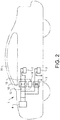
Fig. 2 shows avehicle 30 comprising aswitch control system 1 according to the invention. The switch control system may be positioned at any suitable place in the vehicle, but is preferably arranged close to the high-voltage energy storage or the high voltage load in order to minimize the cable length of the high voltage cables. Both the high side and the low side of the high voltage require a separate cable. The low voltage system is provided with aground connection 9. -
Fig. 3 shows a schematic flow chart of the method for charging and discharging a high-voltage capacitor in a vehicle comprising a high voltage load and a high voltage energy storage. The method is performed before the vehicle is started and after the vehicle has been stopped, and the vehicle may be a pure electric vehicle or may be a hybrid vehicle. The method steps are preferably performed by a computer program and a computer program product contained and run in the electronic control unit of the vehicle. - In
step 100, the DC-link high-voltage capacitor is pre-charge with a bidirectional DC/DC-converter from a low voltage energy storage before the vehicle is started. When a pure electric vehicle is to be started, an activation switch is activated which sets the vehicle in a stand-by mode. For a hybrid vehicle, the ignition switch is set to a first position. The low voltage electric system of the vehicle is now active, such that lamps, entertainment system, navigation etc. are active. At the same time, the DC-link capacitor is pre-charge with a bidirectional DC/DC-converter from a low voltage energy storage. The DC-link capacitor is pre-charge to substantially the same voltage as the high voltage energy storage. - In
step 110, the high voltage energy storage is connected to the high voltage load with a switching member. The switching member is closed when the voltage difference between the input side and the output side of the switching member is below a predefined value. The vehicle is now ready to be driven by a user. - In
step 120, the vehicle has been stopped. The activation switch or the ignition switch has been turned to an off-position, indicating that the vehicle will not be used for a while and that is to be shut-off. The high voltage energy storage will now be disconnected from the high voltage load. - In
step 130, the DC-link capacitor is discharged with the bidirectional DC/DC-converter. The voltage of the DC-link capacitor is transformed to the voltage of the low voltage energy storage by the bi-directional DC/DC-converter, such that the energy of the DC-link capacitor is transferred to the low voltage energy storage. The switch control unit can then be switched off as well. - The invention is not to be regarded as being limited to the embodiments described above, a number of additional variants and modifications being possible within the scope of the subsequent patent claims.
-
- 1:
- Switch control system
- 2:
- High voltage battery
- 3:
- Low voltage battery
- 4:
- High voltage load
- 5:
- Bi-directional DC/DC converter
- 6:
- DC-link capacitor
- 7:
- Input side
- 8:
- Output side
- 9:
- Ground
- 10:
- High voltage switching member
- 11:
- Switch control unit
- 12:
- First voltage sensor
- 13:
- Second voltage sensor
- 30:
- Vehicle
Claims (13)
- A switch control system (1) comprising a switching member (10), a high voltage load (4), a high voltage energy storage (2), a bi-directional DC/DC-converter (5) operatively connected to the switching member (10), a high-voltage capacitor (6) operatively connected to the high-voltage load (4), and a low voltage energy storage (3) operatively connected to the bi-directional DC/DC-converter (5), wherein the switching member (10) is adapted to connect and disconnect the high voltage energy storage (2) to and from the high voltage load (4), characterized in that the bi-directional DC/DC-converter (5) is adapted to pre-charge the high-voltage capacitor (6) to a predefined voltage value from the low voltage energy storage (3) before the switching member (10) is closed and adapted to discharge the high-voltage capacitor (6) to the low voltage energy storage (3) when the switching member (10) has been opened and wherein the predefined voltage value is set to alternate between a voltage value that is sometimes lower than the voltage of the high voltage energy storage and that is sometimes higher than the voltage of the high voltage energy storage.
- Switch control system according to claim 1, characterized in that the system comprises a first voltage sensor (12) operatively connected to a first side of the switching member (10) and a second voltage sensor (13) operatively connected to a second side of the switching member (10).
- Switch control system according to claim 2, characterized in that the system comprises a control unit (11) adapted to receive voltage values from the first voltage sensor (12) and the second voltage sensor (13), to determine the predefined voltage value and to control the switching member (10) in dependency of the determined predefined voltage value.
- Switch control system according to any of claims 1 to 3, characterized in that the predefined voltage value is dependent on the voltage of the high-voltage energy storage (2).
- Switch control system according to any of claims 1 to 4, characterized in that predefined voltage value differs from the voltage of the high-voltage energy storage (2) by less than 1%.
- Switch control system according to any of claims 1 to 4, characterized in that predefined voltage value is higher than the voltage of the low-voltage energy storage (3).
- Switch control system according to any of claims 1 to 6, characterized in that the low-voltage energy storage (3) consists of a first lead-acid battery and a second different low-voltage energy storage.
- Vehicle, wherein the vehicle (30) comprises a switch control system (1) according to any of the preceding claims.
- Vehicle according to claim 8, wherein the vehicle (1) is a hybrid vehicle.
- A method for charging and discharging a high-voltage capacitor (6) in a vehicle comprising a high voltage load (4) with a high-voltage capacitor (6), and a high voltage energy storage (2), comprising the steps of:- pre-charging the high-voltage capacitor to a predefined voltage value with a bidirectional DC/DC-converter (5) from a low voltage energy storage (3) before the vehicle is started,- connecting the high voltage energy storage to the high voltage load with a switching member (10) when the voltage difference between the input side and the output side of the switching member is below a predefined value,- disconnecting the high voltage energy storage from the high voltage load after the vehicle is stopped,- discharging the high-voltage capacitor with the bidirectional DC/DC-converter to the low voltage energy storage, where the predefined voltage value is higher than the voltage of the high-voltage energy storage at one start moment of the vehicle, and that the predefined voltage value is lower than the voltage of the high-voltage energy storage at another start moment of the vehicle.
- A method according to claim 10, comprising the additional step of:
waiting a predefined time interval before the high-voltage capacitor is discharged with the bi-directional DC/DC-converter. - A computer program comprising program code means for performing all the steps of claims 10 or 11 when said program is run on a computer.
- A computer program product comprising program code means stored on a computer readable medium for performing all the steps of claims 10 or 11 when said program product is run on a computer.
Priority Applications (4)
| Application Number | Priority Date | Filing Date | Title |
|---|---|---|---|
| EP17201270.0A EP3482994B1 (en) | 2017-11-13 | 2017-11-13 | Contactor control system and method for controlling a contactor |
| PCT/CN2018/114892 WO2019091465A1 (en) | 2017-11-13 | 2018-11-09 | Contactor control system and method for controlling a contactor |
| CN201880072573.1A CN111315610B (en) | 2017-11-13 | 2018-11-09 | Contactor control system and method for controlling contactor |
| US16/872,887 US11878603B2 (en) | 2017-11-13 | 2020-05-12 | Contactor control system and method for controlling a contactor |
Applications Claiming Priority (1)
| Application Number | Priority Date | Filing Date | Title |
|---|---|---|---|
| EP17201270.0A EP3482994B1 (en) | 2017-11-13 | 2017-11-13 | Contactor control system and method for controlling a contactor |
Publications (2)
| Publication Number | Publication Date |
|---|---|
| EP3482994A1 EP3482994A1 (en) | 2019-05-15 |
| EP3482994B1 true EP3482994B1 (en) | 2020-07-22 |
Family
ID=60327110
Family Applications (1)
| Application Number | Title | Priority Date | Filing Date |
|---|---|---|---|
| EP17201270.0A Active EP3482994B1 (en) | 2017-11-13 | 2017-11-13 | Contactor control system and method for controlling a contactor |
Country Status (4)
| Country | Link |
|---|---|
| US (1) | US11878603B2 (en) |
| EP (1) | EP3482994B1 (en) |
| CN (1) | CN111315610B (en) |
| WO (1) | WO2019091465A1 (en) |
Families Citing this family (4)
| Publication number | Priority date | Publication date | Assignee | Title |
|---|---|---|---|---|
| CN113022466A (en) * | 2019-12-05 | 2021-06-25 | 观致汽车有限公司 | Electric automobile and control method and device thereof |
| CN111660871A (en) * | 2020-05-15 | 2020-09-15 | 浙江飞碟汽车制造有限公司 | Novel power supply system and power supply method of new energy automobile |
| FR3114930B1 (en) * | 2020-10-02 | 2022-10-28 | Safran Electrical & Power | System for generating electrical energy to supply an aircraft load and use of such a system |
| CN115071430A (en) * | 2022-08-23 | 2022-09-20 | 江苏智能无人装备产业创新中心有限公司 | Pre-charging relay redundancy control method and device based on bidirectional power supply |
Family Cites Families (15)
| Publication number | Priority date | Publication date | Assignee | Title |
|---|---|---|---|---|
| US5440180A (en) * | 1992-09-28 | 1995-08-08 | Eaton Corporation | Microprocessor based electrical contactor with distributed contactor opening |
| JP3886733B2 (en) * | 2001-04-03 | 2007-02-28 | 矢崎総業株式会社 | Vehicle power supply |
| JP3625789B2 (en) * | 2001-08-10 | 2005-03-02 | 本田技研工業株式会社 | Vehicle power supply |
| JP2007318849A (en) * | 2006-05-24 | 2007-12-06 | Toyota Motor Corp | Electric system of electric automobile |
| JP5831760B2 (en) * | 2012-04-05 | 2015-12-09 | 株式会社デンソー | Abnormality diagnosis device for power supply control system |
| US9925878B2 (en) * | 2013-09-26 | 2018-03-27 | Ford Global Technologies, Llc | Bus pre-charge control using a buck converter |
| DE102013225884A1 (en) | 2013-12-13 | 2015-06-18 | Volkswagen Aktiengesellschaft | Precharging an electric DC link memory |
| WO2015124161A1 (en) * | 2014-02-24 | 2015-08-27 | Volvo Truck Corporation | Electrical storage system for a vehicle and method for controlling said system |
| US9413184B2 (en) | 2014-03-21 | 2016-08-09 | Lg Chem, Ltd. | Pre-charging and voltage supply system for a DC-AC inverter |
| KR102302783B1 (en) | 2014-07-25 | 2021-09-16 | 현대모비스 주식회사 | Vehicle Driving System and Method |
| JP6201967B2 (en) | 2014-11-26 | 2017-09-27 | トヨタ自動車株式会社 | Electric car |
| US10232735B2 (en) * | 2015-10-22 | 2019-03-19 | Denso Corporation | Control device for power supply system |
| CN107554335B (en) * | 2017-08-30 | 2020-02-18 | 奇瑞新能源汽车技术有限公司 | Vehicle-mounted power system and automobile |
| CN207339369U (en) * | 2017-10-31 | 2018-05-08 | 北京新能源汽车股份有限公司 | A kind of charging circuit and electric automobile |
| CN108422889A (en) * | 2018-04-28 | 2018-08-21 | 东南(福建)汽车工业有限公司 | A kind of preliminary filling control circuit and control method for electric vehicle |
-
2017
- 2017-11-13 EP EP17201270.0A patent/EP3482994B1/en active Active
-
2018
- 2018-11-09 WO PCT/CN2018/114892 patent/WO2019091465A1/en active Application Filing
- 2018-11-09 CN CN201880072573.1A patent/CN111315610B/en active Active
-
2020
- 2020-05-12 US US16/872,887 patent/US11878603B2/en active Active
Non-Patent Citations (1)
| Title |
|---|
| None * |
Also Published As
| Publication number | Publication date |
|---|---|
| CN111315610A (en) | 2020-06-19 |
| CN111315610B (en) | 2021-12-17 |
| US11878603B2 (en) | 2024-01-23 |
| US20200269718A1 (en) | 2020-08-27 |
| WO2019091465A1 (en) | 2019-05-16 |
| EP3482994A1 (en) | 2019-05-15 |
Similar Documents
| Publication | Publication Date | Title |
|---|---|---|
| US11878603B2 (en) | Contactor control system and method for controlling a contactor | |
| US9956882B2 (en) | Electric power storage system | |
| US10160325B2 (en) | Vehicle power control method and system for jump-start | |
| US9002558B2 (en) | Abnormality diagnosis apparatus for power control system | |
| US7806095B2 (en) | Vehicle starting assist system | |
| CA2860940C (en) | System and method for high voltage cable detection in hybrid vehicles | |
| US10131298B2 (en) | Controlled connection of multiple wiring system branches of a vehicle | |
| CN102161315A (en) | Vehicle power supply apparatus | |
| CN102205788B (en) | For the battery charging system of motor vehicle driven by mixed power | |
| RU2688930C2 (en) | Device and method of controlling charging and discharging of supercondensers | |
| CN102343877A (en) | Low voltage bus stability | |
| KR101866063B1 (en) | System for controlling relay of an auxiliary battery and method thereof | |
| KR20070020695A (en) | Inrush current preventing device of a HEV | |
| KR20140068556A (en) | Control method of DC-DC converter for electric vehicle | |
| CN108879813B (en) | Proximity detection device and method | |
| EP3425766B1 (en) | A capacitor module | |
| US20170305414A1 (en) | Hybrid vehicle | |
| KR102336964B1 (en) | Battery for hybrid vehicle and control method thereof | |
| CN110654251B (en) | Method for charging a high-voltage battery in a traction power grid and traction power grid | |
| US20170130689A1 (en) | Ignition apparatus and ignition control method |
Legal Events
| Date | Code | Title | Description |
|---|---|---|---|
| PUAI | Public reference made under article 153(3) epc to a published international application that has entered the european phase |
Free format text: ORIGINAL CODE: 0009012 |
|
| STAA | Information on the status of an ep patent application or granted ep patent |
Free format text: STATUS: REQUEST FOR EXAMINATION WAS MADE |
|
| 17P | Request for examination filed |
Effective date: 20171113 |
|
| AK | Designated contracting states |
Kind code of ref document: A1 Designated state(s): AL AT BE BG CH CY CZ DE DK EE ES FI FR GB GR HR HU IE IS IT LI LT LU LV MC MK MT NL NO PL PT RO RS SE SI SK SM TR |
|
| AX | Request for extension of the european patent |
Extension state: BA ME |
|
| GRAP | Despatch of communication of intention to grant a patent |
Free format text: ORIGINAL CODE: EPIDOSNIGR1 |
|
| STAA | Information on the status of an ep patent application or granted ep patent |
Free format text: STATUS: GRANT OF PATENT IS INTENDED |
|
| RAP1 | Party data changed (applicant data changed or rights of an application transferred) |
Owner name: NINGBO GEELY AUTOMOBILE RESEARCH & DEVELOPMENT CO., LTD. |
|
| INTG | Intention to grant announced |
Effective date: 20200324 |
|
| GRAS | Grant fee paid |
Free format text: ORIGINAL CODE: EPIDOSNIGR3 |
|
| GRAA | (expected) grant |
Free format text: ORIGINAL CODE: 0009210 |
|
| STAA | Information on the status of an ep patent application or granted ep patent |
Free format text: STATUS: THE PATENT HAS BEEN GRANTED |
|
| AK | Designated contracting states |
Kind code of ref document: B1 Designated state(s): AL AT BE BG CH CY CZ DE DK EE ES FI FR GB GR HR HU IE IS IT LI LT LU LV MC MK MT NL NO PL PT RO RS SE SI SK SM TR |
|
| REG | Reference to a national code |
Ref country code: GB Ref legal event code: FG4D |
|
| REG | Reference to a national code |
Ref country code: CH Ref legal event code: EP |
|
| REG | Reference to a national code |
Ref country code: DE Ref legal event code: R096 Ref document number: 602017020105 Country of ref document: DE |
|
| REG | Reference to a national code |
Ref country code: AT Ref legal event code: REF Ref document number: 1293080 Country of ref document: AT Kind code of ref document: T Effective date: 20200815 |
|
| REG | Reference to a national code |
Ref country code: IE Ref legal event code: FG4D |
|
| REG | Reference to a national code |
Ref country code: LT Ref legal event code: MG4D |
|
| REG | Reference to a national code |
Ref country code: AT Ref legal event code: MK05 Ref document number: 1293080 Country of ref document: AT Kind code of ref document: T Effective date: 20200722 |
|
| PG25 | Lapsed in a contracting state [announced via postgrant information from national office to epo] |
Ref country code: FI Free format text: LAPSE BECAUSE OF FAILURE TO SUBMIT A TRANSLATION OF THE DESCRIPTION OR TO PAY THE FEE WITHIN THE PRESCRIBED TIME-LIMIT Effective date: 20200722 Ref country code: AT Free format text: LAPSE BECAUSE OF FAILURE TO SUBMIT A TRANSLATION OF THE DESCRIPTION OR TO PAY THE FEE WITHIN THE PRESCRIBED TIME-LIMIT Effective date: 20200722 Ref country code: NO Free format text: LAPSE BECAUSE OF FAILURE TO SUBMIT A TRANSLATION OF THE DESCRIPTION OR TO PAY THE FEE WITHIN THE PRESCRIBED TIME-LIMIT Effective date: 20201022 Ref country code: GR Free format text: LAPSE BECAUSE OF FAILURE TO SUBMIT A TRANSLATION OF THE DESCRIPTION OR TO PAY THE FEE WITHIN THE PRESCRIBED TIME-LIMIT Effective date: 20201023 Ref country code: ES Free format text: LAPSE BECAUSE OF FAILURE TO SUBMIT A TRANSLATION OF THE DESCRIPTION OR TO PAY THE FEE WITHIN THE PRESCRIBED TIME-LIMIT Effective date: 20200722 Ref country code: SE Free format text: LAPSE BECAUSE OF FAILURE TO SUBMIT A TRANSLATION OF THE DESCRIPTION OR TO PAY THE FEE WITHIN THE PRESCRIBED TIME-LIMIT Effective date: 20200722 Ref country code: BG Free format text: LAPSE BECAUSE OF FAILURE TO SUBMIT A TRANSLATION OF THE DESCRIPTION OR TO PAY THE FEE WITHIN THE PRESCRIBED TIME-LIMIT Effective date: 20201022 Ref country code: PT Free format text: LAPSE BECAUSE OF FAILURE TO SUBMIT A TRANSLATION OF THE DESCRIPTION OR TO PAY THE FEE WITHIN THE PRESCRIBED TIME-LIMIT Effective date: 20201123 Ref country code: HR Free format text: LAPSE BECAUSE OF FAILURE TO SUBMIT A TRANSLATION OF THE DESCRIPTION OR TO PAY THE FEE WITHIN THE PRESCRIBED TIME-LIMIT Effective date: 20200722 Ref country code: LT Free format text: LAPSE BECAUSE OF FAILURE TO SUBMIT A TRANSLATION OF THE DESCRIPTION OR TO PAY THE FEE WITHIN THE PRESCRIBED TIME-LIMIT Effective date: 20200722 |
|
| PG25 | Lapsed in a contracting state [announced via postgrant information from national office to epo] |
Ref country code: RS Free format text: LAPSE BECAUSE OF FAILURE TO SUBMIT A TRANSLATION OF THE DESCRIPTION OR TO PAY THE FEE WITHIN THE PRESCRIBED TIME-LIMIT Effective date: 20200722 Ref country code: LV Free format text: LAPSE BECAUSE OF FAILURE TO SUBMIT A TRANSLATION OF THE DESCRIPTION OR TO PAY THE FEE WITHIN THE PRESCRIBED TIME-LIMIT Effective date: 20200722 Ref country code: PL Free format text: LAPSE BECAUSE OF FAILURE TO SUBMIT A TRANSLATION OF THE DESCRIPTION OR TO PAY THE FEE WITHIN THE PRESCRIBED TIME-LIMIT Effective date: 20200722 Ref country code: IS Free format text: LAPSE BECAUSE OF FAILURE TO SUBMIT A TRANSLATION OF THE DESCRIPTION OR TO PAY THE FEE WITHIN THE PRESCRIBED TIME-LIMIT Effective date: 20201122 |
|
| PG25 | Lapsed in a contracting state [announced via postgrant information from national office to epo] |
Ref country code: NL Free format text: LAPSE BECAUSE OF FAILURE TO SUBMIT A TRANSLATION OF THE DESCRIPTION OR TO PAY THE FEE WITHIN THE PRESCRIBED TIME-LIMIT Effective date: 20200722 |
|
| REG | Reference to a national code |
Ref country code: DE Ref legal event code: R097 Ref document number: 602017020105 Country of ref document: DE |
|
| PG25 | Lapsed in a contracting state [announced via postgrant information from national office to epo] |
Ref country code: RO Free format text: LAPSE BECAUSE OF FAILURE TO SUBMIT A TRANSLATION OF THE DESCRIPTION OR TO PAY THE FEE WITHIN THE PRESCRIBED TIME-LIMIT Effective date: 20200722 Ref country code: CZ Free format text: LAPSE BECAUSE OF FAILURE TO SUBMIT A TRANSLATION OF THE DESCRIPTION OR TO PAY THE FEE WITHIN THE PRESCRIBED TIME-LIMIT Effective date: 20200722 Ref country code: DK Free format text: LAPSE BECAUSE OF FAILURE TO SUBMIT A TRANSLATION OF THE DESCRIPTION OR TO PAY THE FEE WITHIN THE PRESCRIBED TIME-LIMIT Effective date: 20200722 Ref country code: SM Free format text: LAPSE BECAUSE OF FAILURE TO SUBMIT A TRANSLATION OF THE DESCRIPTION OR TO PAY THE FEE WITHIN THE PRESCRIBED TIME-LIMIT Effective date: 20200722 Ref country code: EE Free format text: LAPSE BECAUSE OF FAILURE TO SUBMIT A TRANSLATION OF THE DESCRIPTION OR TO PAY THE FEE WITHIN THE PRESCRIBED TIME-LIMIT Effective date: 20200722 Ref country code: IT Free format text: LAPSE BECAUSE OF FAILURE TO SUBMIT A TRANSLATION OF THE DESCRIPTION OR TO PAY THE FEE WITHIN THE PRESCRIBED TIME-LIMIT Effective date: 20200722 |
|
| PLBE | No opposition filed within time limit |
Free format text: ORIGINAL CODE: 0009261 |
|
| STAA | Information on the status of an ep patent application or granted ep patent |
Free format text: STATUS: NO OPPOSITION FILED WITHIN TIME LIMIT |
|
| PG25 | Lapsed in a contracting state [announced via postgrant information from national office to epo] |
Ref country code: AL Free format text: LAPSE BECAUSE OF FAILURE TO SUBMIT A TRANSLATION OF THE DESCRIPTION OR TO PAY THE FEE WITHIN THE PRESCRIBED TIME-LIMIT Effective date: 20200722 |
|
| 26N | No opposition filed |
Effective date: 20210423 |
|
| PG25 | Lapsed in a contracting state [announced via postgrant information from national office to epo] |
Ref country code: MC Free format text: LAPSE BECAUSE OF FAILURE TO SUBMIT A TRANSLATION OF THE DESCRIPTION OR TO PAY THE FEE WITHIN THE PRESCRIBED TIME-LIMIT Effective date: 20200722 Ref country code: SK Free format text: LAPSE BECAUSE OF FAILURE TO SUBMIT A TRANSLATION OF THE DESCRIPTION OR TO PAY THE FEE WITHIN THE PRESCRIBED TIME-LIMIT Effective date: 20200722 |
|
| REG | Reference to a national code |
Ref country code: CH Ref legal event code: PL |
|
| PG25 | Lapsed in a contracting state [announced via postgrant information from national office to epo] |
Ref country code: LU Free format text: LAPSE BECAUSE OF NON-PAYMENT OF DUE FEES Effective date: 20201113 |
|
| REG | Reference to a national code |
Ref country code: BE Ref legal event code: MM Effective date: 20201130 |
|
| PG25 | Lapsed in a contracting state [announced via postgrant information from national office to epo] |
Ref country code: SI Free format text: LAPSE BECAUSE OF FAILURE TO SUBMIT A TRANSLATION OF THE DESCRIPTION OR TO PAY THE FEE WITHIN THE PRESCRIBED TIME-LIMIT Effective date: 20200722 Ref country code: LI Free format text: LAPSE BECAUSE OF NON-PAYMENT OF DUE FEES Effective date: 20201130 Ref country code: CH Free format text: LAPSE BECAUSE OF NON-PAYMENT OF DUE FEES Effective date: 20201130 |
|
| REG | Reference to a national code |
Ref country code: NL Ref legal event code: MP Effective date: 20200722 |
|
| PG25 | Lapsed in a contracting state [announced via postgrant information from national office to epo] |
Ref country code: IE Free format text: LAPSE BECAUSE OF NON-PAYMENT OF DUE FEES Effective date: 20201113 |
|
| PG25 | Lapsed in a contracting state [announced via postgrant information from national office to epo] |
Ref country code: TR Free format text: LAPSE BECAUSE OF FAILURE TO SUBMIT A TRANSLATION OF THE DESCRIPTION OR TO PAY THE FEE WITHIN THE PRESCRIBED TIME-LIMIT Effective date: 20200722 Ref country code: MT Free format text: LAPSE BECAUSE OF FAILURE TO SUBMIT A TRANSLATION OF THE DESCRIPTION OR TO PAY THE FEE WITHIN THE PRESCRIBED TIME-LIMIT Effective date: 20200722 Ref country code: CY Free format text: LAPSE BECAUSE OF FAILURE TO SUBMIT A TRANSLATION OF THE DESCRIPTION OR TO PAY THE FEE WITHIN THE PRESCRIBED TIME-LIMIT Effective date: 20200722 |
|
| PG25 | Lapsed in a contracting state [announced via postgrant information from national office to epo] |
Ref country code: MK Free format text: LAPSE BECAUSE OF FAILURE TO SUBMIT A TRANSLATION OF THE DESCRIPTION OR TO PAY THE FEE WITHIN THE PRESCRIBED TIME-LIMIT Effective date: 20200722 |
|
| PG25 | Lapsed in a contracting state [announced via postgrant information from national office to epo] |
Ref country code: BE Free format text: LAPSE BECAUSE OF NON-PAYMENT OF DUE FEES Effective date: 20201130 |
|
| PGFP | Annual fee paid to national office [announced via postgrant information from national office to epo] |
Ref country code: GB Payment date: 20231120 Year of fee payment: 7 |
|
| PGFP | Annual fee paid to national office [announced via postgrant information from national office to epo] |
Ref country code: FR Payment date: 20231124 Year of fee payment: 7 Ref country code: DE Payment date: 20231107 Year of fee payment: 7 |