EP3482990A1 - Vehicle - Google Patents
Vehicle Download PDFInfo
- Publication number
- EP3482990A1 EP3482990A1 EP17824039.6A EP17824039A EP3482990A1 EP 3482990 A1 EP3482990 A1 EP 3482990A1 EP 17824039 A EP17824039 A EP 17824039A EP 3482990 A1 EP3482990 A1 EP 3482990A1
- Authority
- EP
- European Patent Office
- Prior art keywords
- exhaust duct
- muffler
- engine
- open
- opening
- Prior art date
- Legal status (The legal status is an assumption and is not a legal conclusion. Google has not performed a legal analysis and makes no representation as to the accuracy of the status listed.)
- Granted
Links
- 230000003584 silencer Effects 0.000 claims abstract description 10
- 238000001816 cooling Methods 0.000 claims description 19
- 230000005540 biological transmission Effects 0.000 description 21
- 238000009413 insulation Methods 0.000 description 14
- 230000002238 attenuated effect Effects 0.000 description 9
- 239000002828 fuel tank Substances 0.000 description 7
- 239000000725 suspension Substances 0.000 description 7
- 241000276425 Xiphophorus maculatus Species 0.000 description 4
- 239000006096 absorbing agent Substances 0.000 description 3
- 230000035939 shock Effects 0.000 description 3
- 229910001220 stainless steel Inorganic materials 0.000 description 3
- 239000010935 stainless steel Substances 0.000 description 3
- 230000006866 deterioration Effects 0.000 description 2
- 238000007599 discharging Methods 0.000 description 2
- 239000000446 fuel Substances 0.000 description 2
- 239000011491 glass wool Substances 0.000 description 2
- 230000001902 propagating effect Effects 0.000 description 2
- 230000001012 protector Effects 0.000 description 2
- 239000011347 resin Substances 0.000 description 2
- 229920005989 resin Polymers 0.000 description 2
- 239000011358 absorbing material Substances 0.000 description 1
- 238000007796 conventional method Methods 0.000 description 1
- 230000000694 effects Effects 0.000 description 1
- 230000005484 gravity Effects 0.000 description 1
- 230000012447 hatching Effects 0.000 description 1
- 238000002347 injection Methods 0.000 description 1
- 239000007924 injection Substances 0.000 description 1
- 239000002184 metal Substances 0.000 description 1
- 239000000243 solution Substances 0.000 description 1
Images


Classifications
-
- B—PERFORMING OPERATIONS; TRANSPORTING
- B60—VEHICLES IN GENERAL
- B60K—ARRANGEMENT OR MOUNTING OF PROPULSION UNITS OR OF TRANSMISSIONS IN VEHICLES; ARRANGEMENT OR MOUNTING OF PLURAL DIVERSE PRIME-MOVERS IN VEHICLES; AUXILIARY DRIVES FOR VEHICLES; INSTRUMENTATION OR DASHBOARDS FOR VEHICLES; ARRANGEMENTS IN CONNECTION WITH COOLING, AIR INTAKE, GAS EXHAUST OR FUEL SUPPLY OF PROPULSION UNITS IN VEHICLES
- B60K13/00—Arrangement in connection with combustion air intake or gas exhaust of propulsion units
- B60K13/04—Arrangement in connection with combustion air intake or gas exhaust of propulsion units concerning exhaust
-
- B—PERFORMING OPERATIONS; TRANSPORTING
- B60—VEHICLES IN GENERAL
- B60K—ARRANGEMENT OR MOUNTING OF PROPULSION UNITS OR OF TRANSMISSIONS IN VEHICLES; ARRANGEMENT OR MOUNTING OF PLURAL DIVERSE PRIME-MOVERS IN VEHICLES; AUXILIARY DRIVES FOR VEHICLES; INSTRUMENTATION OR DASHBOARDS FOR VEHICLES; ARRANGEMENTS IN CONNECTION WITH COOLING, AIR INTAKE, GAS EXHAUST OR FUEL SUPPLY OF PROPULSION UNITS IN VEHICLES
- B60K5/00—Arrangement or mounting of internal-combustion or jet-propulsion units
-
- B—PERFORMING OPERATIONS; TRANSPORTING
- B62—LAND VEHICLES FOR TRAVELLING OTHERWISE THAN ON RAILS
- B62D—MOTOR VEHICLES; TRAILERS
- B62D21/00—Understructures, i.e. chassis frame on which a vehicle body may be mounted
- B62D21/18—Understructures, i.e. chassis frame on which a vehicle body may be mounted characterised by the vehicle type and not provided for in groups B62D21/02 - B62D21/17
- B62D21/183—Understructures, i.e. chassis frame on which a vehicle body may be mounted characterised by the vehicle type and not provided for in groups B62D21/02 - B62D21/17 specially adapted for sports vehicles, e.g. race, dune buggies, go-karts
-
- B—PERFORMING OPERATIONS; TRANSPORTING
- B62—LAND VEHICLES FOR TRAVELLING OTHERWISE THAN ON RAILS
- B62D—MOTOR VEHICLES; TRAILERS
- B62D25/00—Superstructure or monocoque structure sub-units; Parts or details thereof not otherwise provided for
- B62D25/20—Floors or bottom sub-units
- B62D25/2072—Floor protection, e.g. from corrosion or scratching
-
- F—MECHANICAL ENGINEERING; LIGHTING; HEATING; WEAPONS; BLASTING
- F01—MACHINES OR ENGINES IN GENERAL; ENGINE PLANTS IN GENERAL; STEAM ENGINES
- F01N—GAS-FLOW SILENCERS OR EXHAUST APPARATUS FOR MACHINES OR ENGINES IN GENERAL; GAS-FLOW SILENCERS OR EXHAUST APPARATUS FOR INTERNAL COMBUSTION ENGINES
- F01N1/00—Silencing apparatus characterised by method of silencing
- F01N1/08—Silencing apparatus characterised by method of silencing by reducing exhaust energy by throttling or whirling
-
- F—MECHANICAL ENGINEERING; LIGHTING; HEATING; WEAPONS; BLASTING
- F01—MACHINES OR ENGINES IN GENERAL; ENGINE PLANTS IN GENERAL; STEAM ENGINES
- F01N—GAS-FLOW SILENCERS OR EXHAUST APPARATUS FOR MACHINES OR ENGINES IN GENERAL; GAS-FLOW SILENCERS OR EXHAUST APPARATUS FOR INTERNAL COMBUSTION ENGINES
- F01N1/00—Silencing apparatus characterised by method of silencing
- F01N1/24—Silencing apparatus characterised by method of silencing by using sound-absorbing materials
-
- F—MECHANICAL ENGINEERING; LIGHTING; HEATING; WEAPONS; BLASTING
- F01—MACHINES OR ENGINES IN GENERAL; ENGINE PLANTS IN GENERAL; STEAM ENGINES
- F01N—GAS-FLOW SILENCERS OR EXHAUST APPARATUS FOR MACHINES OR ENGINES IN GENERAL; GAS-FLOW SILENCERS OR EXHAUST APPARATUS FOR INTERNAL COMBUSTION ENGINES
- F01N13/00—Exhaust or silencing apparatus characterised by constructional features ; Exhaust or silencing apparatus, or parts thereof, having pertinent characteristics not provided for in, or of interest apart from, groups F01N1/00 - F01N5/00, F01N9/00, F01N11/00
- F01N13/002—Apparatus adapted for particular uses, e.g. for portable devices driven by machines or engines
-
- F—MECHANICAL ENGINEERING; LIGHTING; HEATING; WEAPONS; BLASTING
- F01—MACHINES OR ENGINES IN GENERAL; ENGINE PLANTS IN GENERAL; STEAM ENGINES
- F01N—GAS-FLOW SILENCERS OR EXHAUST APPARATUS FOR MACHINES OR ENGINES IN GENERAL; GAS-FLOW SILENCERS OR EXHAUST APPARATUS FOR INTERNAL COMBUSTION ENGINES
- F01N13/00—Exhaust or silencing apparatus characterised by constructional features ; Exhaust or silencing apparatus, or parts thereof, having pertinent characteristics not provided for in, or of interest apart from, groups F01N1/00 - F01N5/00, F01N9/00, F01N11/00
- F01N13/08—Other arrangements or adaptations of exhaust conduits
- F01N13/082—Other arrangements or adaptations of exhaust conduits of tailpipe, e.g. with means for mixing air with exhaust for exhaust cooling, dilution or evacuation
-
- F—MECHANICAL ENGINEERING; LIGHTING; HEATING; WEAPONS; BLASTING
- F01—MACHINES OR ENGINES IN GENERAL; ENGINE PLANTS IN GENERAL; STEAM ENGINES
- F01N—GAS-FLOW SILENCERS OR EXHAUST APPARATUS FOR MACHINES OR ENGINES IN GENERAL; GAS-FLOW SILENCERS OR EXHAUST APPARATUS FOR INTERNAL COMBUSTION ENGINES
- F01N13/00—Exhaust or silencing apparatus characterised by constructional features ; Exhaust or silencing apparatus, or parts thereof, having pertinent characteristics not provided for in, or of interest apart from, groups F01N1/00 - F01N5/00, F01N9/00, F01N11/00
- F01N13/08—Other arrangements or adaptations of exhaust conduits
- F01N13/085—Other arrangements or adaptations of exhaust conduits having means preventing foreign matter from entering exhaust conduit
-
- F—MECHANICAL ENGINEERING; LIGHTING; HEATING; WEAPONS; BLASTING
- F01—MACHINES OR ENGINES IN GENERAL; ENGINE PLANTS IN GENERAL; STEAM ENGINES
- F01N—GAS-FLOW SILENCERS OR EXHAUST APPARATUS FOR MACHINES OR ENGINES IN GENERAL; GAS-FLOW SILENCERS OR EXHAUST APPARATUS FOR INTERNAL COMBUSTION ENGINES
- F01N13/00—Exhaust or silencing apparatus characterised by constructional features ; Exhaust or silencing apparatus, or parts thereof, having pertinent characteristics not provided for in, or of interest apart from, groups F01N1/00 - F01N5/00, F01N9/00, F01N11/00
- F01N13/14—Exhaust or silencing apparatus characterised by constructional features ; Exhaust or silencing apparatus, or parts thereof, having pertinent characteristics not provided for in, or of interest apart from, groups F01N1/00 - F01N5/00, F01N9/00, F01N11/00 having thermal insulation
- F01N13/141—Double-walled exhaust pipes or housings
- F01N13/143—Double-walled exhaust pipes or housings with air filling the space between both walls
-
- F—MECHANICAL ENGINEERING; LIGHTING; HEATING; WEAPONS; BLASTING
- F01—MACHINES OR ENGINES IN GENERAL; ENGINE PLANTS IN GENERAL; STEAM ENGINES
- F01N—GAS-FLOW SILENCERS OR EXHAUST APPARATUS FOR MACHINES OR ENGINES IN GENERAL; GAS-FLOW SILENCERS OR EXHAUST APPARATUS FOR INTERNAL COMBUSTION ENGINES
- F01N13/00—Exhaust or silencing apparatus characterised by constructional features ; Exhaust or silencing apparatus, or parts thereof, having pertinent characteristics not provided for in, or of interest apart from, groups F01N1/00 - F01N5/00, F01N9/00, F01N11/00
- F01N13/20—Exhaust or silencing apparatus characterised by constructional features ; Exhaust or silencing apparatus, or parts thereof, having pertinent characteristics not provided for in, or of interest apart from, groups F01N1/00 - F01N5/00, F01N9/00, F01N11/00 having flared outlets, e.g. of fish-tail shape
-
- B—PERFORMING OPERATIONS; TRANSPORTING
- B60—VEHICLES IN GENERAL
- B60G—VEHICLE SUSPENSION ARRANGEMENTS
- B60G2300/00—Indexing codes relating to the type of vehicle
- B60G2300/07—Off-road vehicles
-
- B—PERFORMING OPERATIONS; TRANSPORTING
- B60—VEHICLES IN GENERAL
- B60K—ARRANGEMENT OR MOUNTING OF PROPULSION UNITS OR OF TRANSMISSIONS IN VEHICLES; ARRANGEMENT OR MOUNTING OF PLURAL DIVERSE PRIME-MOVERS IN VEHICLES; AUXILIARY DRIVES FOR VEHICLES; INSTRUMENTATION OR DASHBOARDS FOR VEHICLES; ARRANGEMENTS IN CONNECTION WITH COOLING, AIR INTAKE, GAS EXHAUST OR FUEL SUPPLY OF PROPULSION UNITS IN VEHICLES
- B60K5/00—Arrangement or mounting of internal-combustion or jet-propulsion units
- B60K2005/003—Arrangement or mounting of internal-combustion or jet-propulsion units the internal combustion or jet propulsion unit is arranged between the front and the rear axle
-
- B—PERFORMING OPERATIONS; TRANSPORTING
- B60—VEHICLES IN GENERAL
- B60Y—INDEXING SCHEME RELATING TO ASPECTS CROSS-CUTTING VEHICLE TECHNOLOGY
- B60Y2200/00—Type of vehicle
- B60Y2200/20—Off-Road Vehicles
- B60Y2200/23—Ridable golf cars
-
- B—PERFORMING OPERATIONS; TRANSPORTING
- B60—VEHICLES IN GENERAL
- B60Y—INDEXING SCHEME RELATING TO ASPECTS CROSS-CUTTING VEHICLE TECHNOLOGY
- B60Y2400/00—Special features of vehicle units
- B60Y2400/70—Gearings
- B60Y2400/72—Continous variable transmissions [CVT]
-
- F—MECHANICAL ENGINEERING; LIGHTING; HEATING; WEAPONS; BLASTING
- F01—MACHINES OR ENGINES IN GENERAL; ENGINE PLANTS IN GENERAL; STEAM ENGINES
- F01N—GAS-FLOW SILENCERS OR EXHAUST APPARATUS FOR MACHINES OR ENGINES IN GENERAL; GAS-FLOW SILENCERS OR EXHAUST APPARATUS FOR INTERNAL COMBUSTION ENGINES
- F01N2260/00—Exhaust treating devices having provisions not otherwise provided for
- F01N2260/20—Exhaust treating devices having provisions not otherwise provided for for heat or sound protection, e.g. using a shield or specially shaped outer surface of exhaust device
-
- F—MECHANICAL ENGINEERING; LIGHTING; HEATING; WEAPONS; BLASTING
- F01—MACHINES OR ENGINES IN GENERAL; ENGINE PLANTS IN GENERAL; STEAM ENGINES
- F01N—GAS-FLOW SILENCERS OR EXHAUST APPARATUS FOR MACHINES OR ENGINES IN GENERAL; GAS-FLOW SILENCERS OR EXHAUST APPARATUS FOR INTERNAL COMBUSTION ENGINES
- F01N2470/00—Structure or shape of gas passages, pipes or tubes
- F01N2470/02—Tubes being perforated
-
- F—MECHANICAL ENGINEERING; LIGHTING; HEATING; WEAPONS; BLASTING
- F01—MACHINES OR ENGINES IN GENERAL; ENGINE PLANTS IN GENERAL; STEAM ENGINES
- F01N—GAS-FLOW SILENCERS OR EXHAUST APPARATUS FOR MACHINES OR ENGINES IN GENERAL; GAS-FLOW SILENCERS OR EXHAUST APPARATUS FOR INTERNAL COMBUSTION ENGINES
- F01N2590/00—Exhaust or silencing apparatus adapted to particular use, e.g. for military applications, airplanes, submarines
Definitions
- the present invention relates to vehicles, and more specifically to a vehicle including an engine.
- Patent Literature 1 discloses an example of conventional technique in this field.
- Patent Literature 1 discloses a small vehicle in which a drive unit is mounted at a rear region of a vehicle body frame via a sub-frame.
- the drive unit is composed of an engine and a transmission connected to the engine via a V-belt type automatic transmission device.
- a muffler is mounted on the left side of the vehicle and is connected to an engine cylinder via an exhaust pipe.
- a generally L-shaped exhaust gas discharge pipe is connected, and the pipe is routed through a hole formed in a sound insulation board mounted on a lower portion of the sub-frame, and is brought outside.
- the exhaust gas passes through the pipe and is then discharged rearward from below the muffler and the sound insulation board.
- the cylinder is covered with a shroud, which provides a path for a cooling wind.
- a muffler cover which covers the muffler is connected to the shroud.
- the muffler cover has its lower surface formed with an opening, and the opening is above the hole of the sound insulation board.
- the cooling wind is introduced from the shroud into the muffler cover, cools the muffler and thereafter is discharged below via the opening of the muffler cover and the hole of the sound insulation board.
- Patent Literature 1 JP-A 2005-7995
- Patent Literature 1 the pipe connected to the muffler is relatively short and is exposed to the outside from below the sound insulation board. Therefore, there is a possibility that noise from the muffler is not attenuated so much and the noise comes out of the vehicle as the exhaust gas is discharged from the muffler. Also, since the hole in the sound insulation board is located below the opening which is formed in the lower surface of the muffler cover, there is a possibility that noise such as engine vibration noise is not attenuated so much, resulting in noise leakage via the shroud and the muffler cover, out of the vehicle from the hole in the sound insulation board.
- a primary object of the present invention is to provide a vehicle capable of reducing sound leakage out of the vehicle.
- a vehicle which includes an engine having a cylinder body; a muffler to which exhaust gas from the engine is supplied; a shroud covering the cylinder body; a muffler cover covering the muffler and communicating with the shroud; an undercover provided at a lower position than the engine and having an opening; an exhaust duct connected to an exit end portion of the muffler cover; and an engine room having an underside defined by the undercover, and which houses the engine, the muffler, the shroud, the muffler cover and the exhaust duct.
- the opening is located at a more rearward position than the muffler in a side view, and the exhaust duct is routed above the undercover and the exhaust duct has its rearward end portion positioned at the opening in order to discharge the exhaust gas from below the engine room to the outside.
- the exhaust duct is connected to the exit end portion of the muffler cover, and extends rearward above the undercover which is provided at a lower position than the engine, whereas the exhaust duct has its rearward end portion positioned at the opening which is located at a more rearward position than the muffler in a side view.
- Exhaust gas from the muffler passes through the exhaust duct and the opening in the undercover, and is then discharged to the outside from below the engine room. Since the exhaust duct extends rearward so that the rearward end portion of the exhaust duct is located at a more rearward position than the muffler, noise from the muffler is attenuated inside the exhaust duct.
- the exhaust duct is elastic. In this case, it is possible to absorb vertical movements of the muffler cover with the exhaust duct, and it is therefore possible to stably position the rearward end portion of the exhaust duct at the opening of the undercover.
- the exhaust duct is further fitted to the opening.
- the arrangement makes it easy to position and attach the exhaust duct.
- the vehicle further includes a silencer provided at an outlet of the muffler.
- the silencer makes it possible to further attenuate the noise from the muffler, and thereby further reduce noise leakage out of the vehicle.
- the vehicle further includes a sound absorbing member provided on an inner circumferential surface of the exhaust duct.
- the exhaust gas noise emitted from the muffler is attenuated by the sound absorbing member provided on the inner circumferential surface of the exhaust duct, and therefore, it is possible to further reduce noise leakage out of the vehicle.
- the vehicle further includes a discharge pipe provided at the outlet of the muffler, and the sound absorbing member is located in the exhaust duct, on an extended line of a center axis of the discharge pipe.
- the sound absorbing member may be arranged only at necessary place on the inner circumferential surface of the exhaust duct, and therefore it is possible to reduce costs.
- the vehicle further includes a holding member for holding the sound absorbing member on the inner circumferential surface of the exhaust duct, and the holding member is provided by a perforated plate.
- the sound absorbing member reliably on the inner circumferential surface of the exhaust duct while maintaining the sound absorbing capabilities of the sound absorbing member.
- the vehicle further includes an open/close member provided inside the exhaust duct, and the open/close member is configured to be opened when the vehicle is traveling and closed when the vehicle is stopped.
- the open/close member opens, thereby enabling exhaust gas from the muffler to discharge smoothly to the outside from below the engine room via the exhaust duct and the opening of the undercover.
- the open/close member closes, whereby it is possible to further attenuate noises such as noise from the muffler and vibration noise of the engine which propagates through the muffler cover, inside the exhaust duct, and therefore to further reduce noise leakage outside the vehicle.
- the open/close member is further configured to be opened by the exhaust gas passing through the exhaust duct.
- the open/close member there is no need for providing any separate parts for opening the open/close member yet it is possible to open the open/close member.
- the open/close member is opened to an amount in accordance with an exhaust gas pressure received by the open/close member.
- an exhaust gas pressure amount of exhaust gas
- the exhaust gas pressure amount of exhaust gas
- the open/close member is half open, so it is possible to achieve both discharging of the exhaust gas and reducing noise leakage to outside of the vehicle.
- the arrangement is particularly effective when the vehicle is traveling at a constant speed.
- the vehicle further includes a cooling hole provided in the exhaust duct, and the cooling hole penetrates an inner circumferential surface and an outer circumferential surface of the exhaust duct on a more downstream side than the open/close member but near the open/close member in its closed state.
- the cooling hole penetrates an inner circumferential surface and an outer circumferential surface of the exhaust duct on a more downstream side than the open/close member but near the open/close member in its closed state. In this case, it is possible to cool the open/close member and therefore reduce deterioration of the open/close member due to heat.
- the golf car 10 is a two-person golf car, and includes a pair of front wheels 12a, 12b (see Fig. 9 ), a pair of rear wheels 14a, 14b and a frame portion 16.
- the pair of rear wheels 14a, 14b is located at more rearward positions than the pair of front wheels 12a, 12b.
- the pair of front wheels 12a, 12b is supported rotatably at a front region of the frame portion 16.
- the pair of rear wheels 14a, 14b is supported rotatably at a rear region of the frame portion 16.
- the seat portion 18 extends in a width direction of the golf car 10 at a more rearward position than the pair of front wheels 12a, 12b, but at a more forward position than the pair of rear wheels 14a, 14b.
- the seat portion 18 is supported by a seat rail 72 (which will be described later) of the frame portion 16.
- a seat back 20 is provided at an obliquely upward and rearward position of the seat portion 18.
- a basket 22 for accommodating baggage is provided behind the seat back 20.
- the seat back 20 and the basket 22 are supported by rear pillars 26a, 26b which will be described later.
- a pair of front pillars 24a, 24b is provided at more forward positions than the seat portion 18, whereas a pair of rear pillars 26a, 26b is provided at more rearward positions than the seat portion 18.
- the front pillars 24a, 24b and the rear pillars 26a, 26b are supported by the frame portion 16 at their lower end portions.
- the front pillars 24a, 24b and the rear pillars 26a, 26b extend from below to above, while tilting slightly rearward.
- a roof portion 28 covers above the seat portion 18, and is supported by the front pillars 24a, 24b and the rear pillars 26a, 26b.
- a steering wheel 30 is located ahead of the seat back 20.
- the steering wheel 30 is connected to the front wheels 12a, 12b via a steering shaft 32 and an unillustrated connection mechanism.
- the frame portion 16 is covered with a cowl 34, a pair of side protectors 36, a floor panel 38, a body panel 39, a pair of rear fender covers 40a, 40b and a rear floor cover 42, each made of a resin for example.
- the cowl 34 covers the front region of the frame portion 16 and above the front wheels 12a, 12b.
- the pair of side protectors 36 covers an intermediate region of the frame portion 16 from two sides.
- the floor panel 38 which functions as a footrest for the driver and the passenger sitting on the seat portion 18 to rest their feet, provides a bottom portion of a cabin space of the golf car 10.
- the body panel 39 covers a front region below the seat portion 18.
- the pair of rear fender covers 40a, 40b cover two sides below the seat portion 18 and above the pair of rear wheels 14a, 14b.
- the rear floor cover 42 is sandwiched by rear end portions of the pair of rear fender covers 40a, 40b, and has a concave portion 42a for placement of golf bags for example.
- CVT Continuous Variable Transmission
- a transmission 146 which will be described later.
- a holding portion 44 for holding the golf bags.
- the holding portion 44 is supported by connecting members 70a, 70b (which will be described later).
- the frame portion 16 includes a pair of main frames 46a, 46b which are spaced apart from each other in a width direction of the vehicle and extend in a fore-aft direction of the vehicle; cross members 52, 54, 56, 58, and a pair of support frames 60a, 60b.
- the pair of main frames 46a, 46b respectively include front frames 48a, 48b extending in the fore-aft direction; and rear frames 50a, 50b extending rearward from rear end portions of the respective front frames 48a, 48b.
- the pair of front frames 48a, 48b are formed so that their front end portions have a narrower space from each other than their rear end portions do.
- the pair of rear frames 50a, 50b is curved to project upward.
- the front frames 48a, 48b are connected to each other by the cross members 52, 54.
- a portion where the front frame 48a and the rear frame 50a are joined to each other and a portion where the front frame 48b and the rear frame 50b are joined to each other are connected to each other by the cross member 56.
- the rear frames 50a, 50b have their rear end portions connected to each other by the cross member 58.
- the main frames 46a, 46b are connected to each other by the cross members 52, 54, 56, 58 which extend in the vehicle's width direction.
- the cross members 52, 54, 56, 58 are spaced apart from each other in the vehicle's fore-aft direction, and are disposed in this order from a front to a rear of the vehicle.
- the cross member 52 is joined to the pair of support frames 60a, 60b which extend obliquely forward.
- the pair of support frames 60a, 60b have their front end portions support a cross member 62 which extends in the vehicle's width direction. Near the cross member 54 in the pair of front frames 48a, 48b, a pair of support frames 64a, 64b which extend upward are joined. Also, the pair of rear frames 50a, 50b has their front portions connected to each other by a connection frame 66. The pair of rear frames 50a, 50b has their intermediate regions connected to each other by a connection frame 68.
- the connection frame 66 extends in the vehicle's width direction, with its two end portions extending downward, to provide an upward projecting substantially U shape .
- the connection frame 68 extends in the vehicle's width direction, with its two end portions extending downward, to provide an upward projecting substantially U shape.
- connection frames 66 and 68 are spaced apart from each other in the vehicle's fore-aft direction, and are connected to each other by the connecting members 70a, 70b. Further, the pair of support frames 64a, 64b have their upper end portions; the connection frame 66 have two side portions; and these portions are connected to each other by the seat rail 72.
- the seat rail 72 is formed substantially in a C shape extending in a horizontal direction. To the cross member 54, a pair of brackets 74a, 74b are attached side by side in the vehicle's width direction.
- a pair of engine brackets 76a, 76b is joined to the pair of brackets 74a, 74b.
- the engine brackets 76a, 76b are connected to each other via a cross member 78.
- the cross member 78 is joined to a support frame 79 which extends forward and support frames 80a, 80b which extend rearward.
- the support frame 79 has its tip portion formed with a projection 79a.
- the support frames 80a, 80b have their respective rear end portions formed with through-holes 82a, 82b (see Fig. 8 ) .
- On the cross member 78 and the support frames 80a, 80b there is attached an engine bracket 84 for supporting an engine 114 (which will be described later) .
- the cross member 78 is joined to the engine brackets 76a, 76b pivotably in an up-down direction. Accordingly, the engine bracket 84 is also pivotable in the up-down direction.
- the cross member 56 is joined to a pair of frames 86a, 86b which extend rearward.
- the pair of frames 86a, 86b are connected to each other at regions near their rear end portions, by a cross member 88.
- the pair of frames 86a, 86b have their rear end portions joined to the cross member 58.
- the frame portion 16 supports an undercover 90.
- the undercover 90 has a front cover portion 92 and a rear cover portion 94 respectively on its forward and rearward sides.
- the front cover portion 92 is located between the cross members 54 and 56, and is attached to the pair of front frames 48a and 48b, and to the cross members 54 and 56.
- the rear cover portion 94 is located between the cross members 56 and 58, and is attached to the cross members 56 and 88, the frames 86a, 86b, and the rear frames 50a, 50b.
- a pair of inner cowls 95 (the inner cowl on the right side is not shown) are attached respectively.
- the pair of inner cowls 95 is placed between the rear wheels 14a, 14b and the rear fender covers 40a, 40b to cover above the respective rear wheels 14a, 14b.
- the undercover 90, the seat portion 18, the body panel 39, a heat insulation board 176 (which will be described later), a fuel tank 168 (which will be described later), the left and the right inner cowls 95 and the rear floor cover 42 define a space as an engine room S.
- the engine room S is surrounded by the undercover 90, the seat portion 18, the body panel 39, the heat insulation board 176, the fuel tank 168, the left and the right inner cowls 95 and the rear floor cover 42.
- the undercover 90 On an under side, an upper side, a front side, a left side, a right side and a rear side of the engine room S, there are provided the undercover 90, the seat portion 18, the body panel 39, the heat insulation board 176 and the left inner cowl 95, the fuel tank 168 and the right inner cowl 95, and the rear floor cover 42 respectively.
- the undercover 90 is provided at a lower place than the engine 114, and defines an under side of the engine room S.
- the engine room S is surrounded with the undercover 90, the seat portion 18, the body panel 39, the heat insulation board 176, the fuel tank 168, the left and the right inner cowls 95 and the rear floor cover 42, whereby it is possible to reduce leakage of noise of the engine room S to outside of the engine room S.
- the floor panel 38 is placed on the front frames 48a, 48b and the cross member 62 of the above-described frame portion 16.
- the floor panel 38 is placed between the pair of front wheels 12a, 12b and the pair of rear wheels 14a, 14b.
- the floor panel 38 includes a panel main body 96, an opening 98 and a groove portion 100.
- the panel main body 96 includes a first panel portion 102 extending substantially horizontally in the fore-aft direction between the front wheels 12a, 12b and the rear wheels 14a, 14b; a second panel portion 104 placed behind the front wheels 12a, 12b and extending upward from a front end region of the first panel portion 102; and third panel portions 106a, 106b extending rearward from left and right rear end regions of the first panel portion 102.
- the first panel portion 102 is located ahead of the engine room S; the third panel portion 106a is located on the left side of the engine room S; and the third panel portion 106b is located on the right side of the engine room S.
- the second panel portion 104 rises obliquely forward from the front end region of the first panel portion 102.
- the opening 98 is located at a front region of the panel main body 96, i.e., in the second panel portion 104 (see Fig. 10(a)).
- Fig. 10(a) shows the opening 98 with hatching.
- the groove portion 100 communicates with the opening 98 in order to supply external air which is introduced from the opening 98 into a shroud 132 (which will be described later) and into the engine 114, is placed on an upper surface of the panel main body 96, and extends in a fore-aft direction of the panel main body 96.
- the groove portion 100 is continuous from the second panel portion 104 to the first panel portion 102, provides communication between the opening 98 and the engine room S, and is capable of introducing a running wind from ahead of the golf car 10 to the engine room S.
- the groove portion 100 is formed on a slightly righter side than the center, in the vehicle's width direction.
- the opening 98 is placed in a side surface 100a of the groove portion 100.
- a platy member 108 which protrudes forward from a reverse surface (front surface) of the second panel portion 104, is provided on a side of the opening 98. Also, referring to Fig.
- a rectangular plate-like cover portion 110 which is supported by the frame portion 16, is provided ahead of the opening 98. Further, the groove portion 100 is covered by a lid portion 112 (see Fig. 8 ).
- the lid portion 112 is provided by a strip-like platy member formed to a longitudinal shape of the groove portion 100.
- the engine bracket 84 supports the engine 114.
- the engine 114 is an air-cooled engine which provides a single-cylinder, for example.
- the engine 114 provides a fuel injection device 115 which injects fuel into an air intake tube 126.
- the engine 114 is placed behind the first panel portion 102 of the floor panel 38, and includes a cylinder head 116, a cylinder body 118 and a crank case 120.
- the engine 114 is tilted forward.
- An air cleaner 122 is provided above the engine 114.
- the air cleaner 122 is joined to an air intake duct 124 via a joint 123.
- the air intake duct 124 is located on the right side of the air cleaner 122, and includes a cylindrical front duct 124a and a noise-reducing rear duct 124b of a flattened shape. A rear end portion of the front duct 124a and a front end portion of the rear duct 124b are joined to each other. In order to introduce the external air from the groove portion 100, the front duct 124a is disposed to face the groove portion 100 from the engine room S, and a rear end portion of the rear duct 124b is joined to the joint 123. Thus, the air intake duct 124 and the air cleaner 122 communicate with each other. As indicated by Arrow X in Fig.
- the external air which is introduced from ahead and comes through the opening 98 and into the groove portion 100, is then introduced into the air cleaner 122 from the groove portion 100 via the air intake duct 124. Then, after being cleaned by the air cleaner 122, the air is supplied, via the air intake tube 126, into the engine 114.
- the air cleaner 122 is provided between the air intake duct 124 and the engine 114.
- a muffler 128 is provided adjacently on a side (on the left side in the present embodiment) of the engine 114. The engine 114 and the muffler 128 are joined to each other via an exhaust pipe 130. Exhaust gas from the engine 114 is supplied to the muffler 128 via the exhaust pipe 130.
- the cylinder body 118 of the engine 114 is covered by the shroud 132, with an air-flowable gap between the cylinder body 118 and the shroud 132.
- a fan case 134 is provided on a side surface (on the right side surface in the present embodiment) of the engine 114.
- the shroud 132 and the fan case 134 are connected to each other.
- Inside the fan case 134 there is provided a fan 136 for supplying the external air from the groove portion 100 into the shroud 132 (between the shroud 132 and the engine 114).
- the fan 136 is preferably connected to a crank shaft 142 (see Fig. 18 ) and driven thereby.
- the muffler 128 is covered by a muffler cover 138 so that an air-flowable gap is formed between the muffler 128 and the muffler cover 138.
- the shroud 132 and the muffler cover 138 communicate with each other via a duct 139 which covers the exhaust pipe 130. It should be noted here that Fig. 11 , Fig. 12 , Fig. 20 and Fig. 21 do not show the duct 139.
- An exhaust duct 140 is connected to an exit end portion of the muffler cover 138.
- the exhaust duct 140 has its rear end portion exposed to the outside from an opening 92a of the front cover portion 92 (see Fig. 7 , Fig. 20 and Fig. 22 ) .
- the muffler cover 138 is supported by the support frame 79 (see Fig. 4 and Fig. 11 ), as the projection 79a of the support frame 79 is inserted through a hole 141a of a bracket 141 attached on a side surface of the muffler cover 138.
- the external air which is introduced into the shroud 132 by the fan 136 flows between the shroud 132 and the engine 114 (the cylinder body 118), into the muffler cover 138 (between the muffler cover 138 and the muffler 128), and serves as a cooling wind to cool the engine 114 and the muffler 128.
- the air inside the muffler cover 138 flows through the exhaust duct 140 and is discharged from the opening 92a of the front cover portion 92, to the outside, below the engine room S.
- the muffler 128, the muffler cover 138, the exhaust duct 140 and their surroundings will be described later.
- an output from the crank shaft 142 of the engine 114 is transmitted via the CVT (Continuously Variable Transmission) 144 to the transmission 146.
- the CVT 144 is located behind the muffler 128, whereas the transmission 146 is located behind the engine 114, between the pair of rear wheels 14a, 14b.
- the engine 114, the muffler 128, the shroud 132, the muffler cover 138, the exhaust duct 140, the CVT 144 and the transmission 146 described above are housed in the engine room S.
- the transmission 146 is joined to a pair of rotation transmission portions 148a, 148b.
- the rotation transmission portion 148a extends to the left of the transmission 146, and includes a constant-velocity joint 150a, a drive shaft 152a, a constant-velocity joint 154a and an axle 156a.
- the transmission 146 has its output shaft (not illustrated) connected to the drive shaft 152a by the constant-velocity joint 150a, whereas the drive shaft 152a and the axle 156a are connected to each other by the constant-velocity joint 154a.
- the rotation transmission portion 148b extends to the right of the transmission 146, and includes a constant-velocity joint 150b, a drive shaft 152b, a constant-velocity joint 154b and an axle 156b.
- the transmission 146 has its output shaft connected to the drive shaft 152b by the constant-velocity joint 150b, whereas the drive shaft 152b and the axle 156b are connected to each other by the constant-velocity joint 154b.
- the axle 156a supports the rear wheel 14a, whereas the axle 156b supports the rear wheel 14b.
- the through-hole 82a at the rear end portion of the support frame 80a is penetrated by the output shaft of the transmission 146 between the transmission 146 and the constant-velocity joint 150a
- the through-hole 82b at the rear end portion of the support frame 80b is penetrated by the output shaft of the transmission 146 between the transmission 146 and the constant-velocity joint 150b (see Fig. 13 ).
- the pair of rear wheels 14a, 14b is suspended by a pair of suspensions 158a, 158b.
- the pair of suspensions 158a, 158b is provided by independent suspension systems.
- the pair of suspensions 158a, 158b includes knuckles 160a, 160b, arms 162a, 162b and shock absorbers 164a, 164b respectively.
- the knuckle 160a supports the axle 156a rotatably.
- the arm 162a connects a lower portion of the knuckle 160a and the frame 86a to each other.
- the shock absorber 164a has a lower end portion and an upper end portion, respectively joined to an upper end portion of the knuckle 160a and to the connection frame 68.
- the knuckle 160b supports the axle 156b rotatably.
- the arm 162b connects a lower portion of the knuckle 160b and the frame 86b to each other.
- the shock absorber 164b has a lower end portion and an upper end portion, respectively joined to an upper end portion of the knuckle 160b and to the connection frame 68.
- the pair of front wheels 12a, 12b is suspended by a pair of suspensions 166a, 166b attached to the front region of the frame portion 16.
- the pair of suspensions 166a, 166b is provided by independent suspension systems.
- the fuel tank 168 is placed on the right side of the engine 114 and on the third panel portion 106b of the floor panel 38. Between the engine 114 and the fuel tank 168, a sound absorbing member 170 is erected and attached to a side surface of the fuel tank 168. Also, a battery 172 is placed on the left of the muffler cover 138 and on the third panel portion 106a of the floor panel 38. Between the muffler cover 138 and the battery 172, a two-ply structure made of a sound absorbing member 174 and the heat insulation board 176 is erected. It is possible, with the sound absorbing members 170 and 174, to absorb noise from the engine room S, whereas it is possible, with the heat insulation board 176, to reduce heat conducting from the engine room S to the battery 172.
- the muffler 128 has an expansion chamber 178 at its rear portion, which is stuffed with a sound absorbing material such as glass wool for example.
- the expansion chamber 178 reduces exhaust gas noise.
- the expansion chamber 178 is provided with a discharge pipe 180 extending obliquely rearward and downward.
- the muffler 128 has an outlet (where exhaust gas is discharged), at which the discharge pipe 180 is provided.
- the discharge pipe 180 has a rearward end portion, at which a joint exhaust 182 is attached.
- the joint exhaust 182 includes a silencer 184, a seal member 186, a holding member 188, a cap member 190 and a fastener 192.
- the silencer 184 is made of a stainless steel mesh member for example, is provided at the outlet of the muffler 128 via the discharge pipe 180, reduces thrust of the exhaust gas, and alters sound quality of the exhaust gas noise.
- the seal member 186 is hollow cylindrical, and is fitted around a rearward end portion of the discharge pipe 180.
- the cylindrical holding member 188 and the annular cap member 190 are formed integrally with each other, and hold the silencer 184 and the seal member 186.
- the fastener 192 is fitted around an outer circumferential surface of the holding member 188 to tighten the holding member 188 so that the holding member 188 presses the silencer 184 and the seal member 186 radially inward.
- the muffler cover 138 is made of a resin for example, provided with an insulation member (not illustrated) on its inner surface, and formed to have a generally rectangular tubular upper portion and a generally cylindrical lower portion (see Fig. 20 and Fig. 21 ).
- the exhaust duct 140 is made of rubber, for example, is elastic and formed into a flattened shape (see Fig. 20 and Fig. 21 ).
- the exhaust duct 140 extends rearward above the undercover 90 (the front cover portion 92), so that a rearward end portion of the exhaust duct 140 is positioned at the opening 92a of the front cover portion 92 and is fitted into the opening 92a.
- the opening 92a is located at a more rearward position than the muffler 128 in a side view. Also, the opening 92a is located at a more rearward position than the muffler cover 138 in a side view.
- the exhaust duct 140 has recesses 196, 198 respectively at lower and upper portions in its inner circumferential surface.
- portions of an outer circumferential surface of the exhaust duct 140 corresponding to the recesses 196, 198 are rectangularly protruded outward (see Fig. 6 and Fig. 21 ) .
- Sound absorbing members 200, 202 are fitted into the recesses 196, 198 respectively. In this way, the sound absorbing member 200 is arranged on the inner circumferential surface of the exhaust duct 140 on an extended line of a center axis P of the discharge pipe 180 which is provided at the outlet of the muffler 128.
- the sound absorbing member 202 is arranged to be hit by exhaust gas after the gas is bounced by the sound absorbing member 200.
- the sound absorbing members 200, 202 are provided by glass wool.
- holding members 204, 206 are attached to the inner circumferential surface of the exhaust duct 140.
- the holding members 204, 206 are provided to cover the respective sound absorbing members 200, 202, and are fixed with fasteners 208, 210.
- the holding members 204, 206 are provided by perforated plates.
- the perforated plate refers to a platy member having a large number of through-holes.
- the holding members 204, 206 are made of punched metal.
- noise of the exhaust gas emitted from the discharge pipe 180 of the muffler 128 into the exhaust duct 140 is reflected and absorbed by the sound absorbing members 200, 202 as indicated by white arrows.
- thicknesses of the white arrows indicate sound pressures, to show that exhaust gas noise is gradually attenuated.
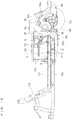
- the exhaust duct 140 which is connected to the exit end portion of the muffler cover 138 extends rearward above the undercover 90 that is provided at a lower position than the engine 114, whereas the exhaust duct 140 has its rearward end portion positioned at the opening 92a which is located at a more rearward position than the muffler 128 in a side view. Exhaust gas from the muffler 128 passes through the exhaust duct 140 and the opening 92a of the undercover 90 (front cover portion 92), and is discharged from below the engine room S to the outside.
- the exhaust duct 140 extends rearward so that the rearward end portion of the exhaust duct 140 is located at a more rearward position than the muffler 128, noise from the muffler 128 is attenuated inside the exhaust duct 140. Also, since the exhaust duct 140 is connected to the muffler cover 138, the cooling wind from the muffler cover 138 passes through the exhaust duct 140 and is discharged from the opening 92a, and noise propagating through the muffler cover 138, such as vibration noise of the engine 114, is attenuated inside the exhaust duct 140. Therefore, it is possible to reduce noise leakage out of the vehicle.
- the exhaust duct 140 is elastic and is capable of absorbing vertical movements of the muffler cover 138, it is possible to stably position the rearward end portion of the exhaust duct 140 at the opening 92a of the undercover 90.
- the silencer 184 makes it possible to further attenuate the noise from the muffler 128, and thereby further reduce noise leakage out of the vehicle.
- the exhaust gas noise emitted from the muffler 128 is attenuated by the sound absorbing members 200, 202 provided on the inner circumferential surface of the exhaust duct 140.
- the arrangement further reduces noise leakage out of the vehicle.
- the sound absorbing members 200, 202 may be arranged only at necessary places on the inner circumferential surface of the exhaust duct 140, the arrangement makes it possible to reduce costs.
- the holding members 204, 206 make it possible to reliably hold the sound absorbing members 200, 202 on the inner circumferential surface of the exhaust duct 140.
- sound absorbing members may be attached to the seat portion 18, the body panel 39, the rear floor cover 42, the undercover 90 and the left and the right inner cowls 95.
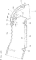
- the exhaust duct 140 may be replaced with an exhaust duct 140a shown in Fig. 25 , with an open/close member 212 provided inside the exhaust duct 140a.
- the exhaust duct 140a is identical with the exhaust duct 140 except that it has a cooling hole 220 (which will be described later).
- the open/close member 212 is configured in such a way that it can be opened when the golf car 10 is moving and it can be closed when the golf car 10 stops.
- the open/close member 212 is configured in such a fashion that it is opened by exhaust gas which passes through the exhaust duct 140a, and it is closed by gravity (own weight) of the open/close member 212.
- An amount of opening (an extent of opening) of the open/close member 212 is set in accordance with exhaust gas pressure received by the open/close member 212.
- Fig. 25 shows a closed state of the open/close member 212 indicated in a solid line and a fully opened state of the open/close member 212 indicated in an alternate long and short dash line. As the exhaust gas pressure (amount of exhaust gas) increases, the degree of opening of the open/close member 212 increases.
- the open/close member 212 is provided by, for example, a stainless steel exhaust gas flap of a slightly curved plate.
- the open/close member 212 is joined, at a widthwise intermediate region of its end portion (upper end portion), to a widthwise intermediate region of an end portion (upper end portion) of the holding member 206 via a hinge 214 made of stainless steel for example.
- the open/close member 212 and the hinge 214 are connected to each other with a fastener 216, whereas the holding member 206 and the hinge 214 are connected to each other with a fastener 218.
- the open/close member 212 is made wider than the holding member 206.
- the open/close member 212 is openable/closable (pivotable) around the hinge 214.
- the open/close member 212 is provided near the opening 92a where the rearward end portion of the exhaust duct 140a is located.
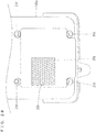
- a cooling hole 220 penetrates an inner circumferential surface and an outer circumferential surface (an upper surface corresponding to the recess 198 in the present embodiment) of the exhaust duct 140a on a more downstream side than but near the open/close member 212 in its closed state.
- the cooling hole 220 is formed above the opening 92a where the rearward end portion of the exhaust duct 140a is located.
- a sound absorbing member 202a in which portions corresponding to the cooling hole 220 is removed, is fitted into the recess 198 of the exhaust duct 140a. Therefore, the holding member 206 is exposed to the outside in the cooling hole 220.
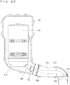
- the open/close member 212 opens, thereby enabling exhaust gas from the muffler 128 to discharge smoothly to the outside from below the engine room S via the exhaust duct 140a and the opening 92a of the undercover 90, as indicated in Fig. 29(a) with a white arrow G.
- the open/close member 212 closes, whereby it is possible to further attenuate noises such as noise from the muffler 128 and vibration noise of the engine 114 which propagates through the muffler cover 138, in the exhaust duct 140a, as indicated in Fig. 29(b) with a white arrow H1, and therefore to further reduce noise leakage out of the vehicle.
- the thicknesses of the white arrow H1 indicate sound pressures.
- the open/close member 212 is configured to be opened by the exhaust gas which passes through the exhaust duct 140a, there is no need for providing any separate parts for opening the open/close member 212, yet it is possible to open the open/close member 212.
- exhaust gas pressure (amount of exhaust gas) is small and the open/close member 212 is half open, so it is possible to achieve both discharging of the exhaust gas and reducing noise leakage to the outside of the vehicle.
- the arrangement is particularly effective when the golf car 10 is traveling at a constant speed.
- open/close member 212 is configured to be closed by its own weight in the embodiment shown in Fig. 25 , the invention is not limited to this.
- the open/close member 212 may be configured to be closed by an elastic member such as a spring.
Abstract
Description
- The present invention relates to vehicles, and more specifically to a vehicle including an engine.
- Patent Literature 1 discloses an example of conventional technique in this field. Patent Literature 1 discloses a small vehicle in which a drive unit is mounted at a rear region of a vehicle body frame via a sub-frame. In the small vehicle, the drive unit is composed of an engine and a transmission connected to the engine via a V-belt type automatic transmission device. A muffler is mounted on the left side of the vehicle and is connected to an engine cylinder via an exhaust pipe. At a lower end portion of the muffler, a generally L-shaped exhaust gas discharge pipe is connected, and the pipe is routed through a hole formed in a sound insulation board mounted on a lower portion of the sub-frame, and is brought outside. The exhaust gas passes through the pipe and is then discharged rearward from below the muffler and the sound insulation board. The cylinder is covered with a shroud, which provides a path for a cooling wind. A muffler cover which covers the muffler is connected to the shroud. The muffler cover has its lower surface formed with an opening, and the opening is above the hole of the sound insulation board. The cooling wind is introduced from the shroud into the muffler cover, cools the muffler and thereafter is discharged below via the opening of the muffler cover and the hole of the sound insulation board.
- Patent Literature 1:
JP-A 2005-7995 - In Patent Literature 1, the pipe connected to the muffler is relatively short and is exposed to the outside from below the sound insulation board. Therefore, there is a possibility that noise from the muffler is not attenuated so much and the noise comes out of the vehicle as the exhaust gas is discharged from the muffler. Also, since the hole in the sound insulation board is located below the opening which is formed in the lower surface of the muffler cover, there is a possibility that noise such as engine vibration noise is not attenuated so much, resulting in noise leakage via the shroud and the muffler cover, out of the vehicle from the hole in the sound insulation board.
- Therefore, a primary object of the present invention is to provide a vehicle capable of reducing sound leakage out of the vehicle.
- According to an aspect of the present invention, a vehicle is provided which includes an engine having a cylinder body; a muffler to which exhaust gas from the engine is supplied; a shroud covering the cylinder body; a muffler cover covering the muffler and communicating with the shroud; an undercover provided at a lower position than the engine and having an opening; an exhaust duct connected to an exit end portion of the muffler cover; and an engine room having an underside defined by the undercover, and which houses the engine, the muffler, the shroud, the muffler cover and the exhaust duct. In this vehicle, the opening is located at a more rearward position than the muffler in a side view, and the exhaust duct is routed above the undercover and the exhaust duct has its rearward end portion positioned at the opening in order to discharge the exhaust gas from below the engine room to the outside.
- In the present invention, the exhaust duct is connected to the exit end portion of the muffler cover, and extends rearward above the undercover which is provided at a lower position than the engine, whereas the exhaust duct has its rearward end portion positioned at the opening which is located at a more rearward position than the muffler in a side view. Exhaust gas from the muffler passes through the exhaust duct and the opening in the undercover, and is then discharged to the outside from below the engine room. Since the exhaust duct extends rearward so that the rearward end portion of the exhaust duct is located at a more rearward position than the muffler, noise from the muffler is attenuated inside the exhaust duct. Also, since the exhaust duct is connected to the muffler cover, a cooling wind from the muffler cover passes through the exhaust duct and is discharged from the opening, whereas noise propagating through the muffler cover such as vibration noise of the engine is attenuated inside the exhaust duct. Therefore, it is possible to reduce noise leakage outside the vehicle.
- Preferably, the exhaust duct is elastic. In this case, it is possible to absorb vertical movements of the muffler cover with the exhaust duct, and it is therefore possible to stably position the rearward end portion of the exhaust duct at the opening of the undercover.
- Preferably, the exhaust duct is further fitted to the opening. In this case, the arrangement makes it easy to position and attach the exhaust duct.
- Preferably, the vehicle further includes a silencer provided at an outlet of the muffler. In this case, the silencer makes it possible to further attenuate the noise from the muffler, and thereby further reduce noise leakage out of the vehicle.
- Preferably, the vehicle further includes a sound absorbing member provided on an inner circumferential surface of the exhaust duct. In this case, the exhaust gas noise emitted from the muffler is attenuated by the sound absorbing member provided on the inner circumferential surface of the exhaust duct, and therefore, it is possible to further reduce noise leakage out of the vehicle.
- Preferably, the vehicle further includes a discharge pipe provided at the outlet of the muffler, and the sound absorbing member is located in the exhaust duct, on an extended line of a center axis of the discharge pipe. In this case, the sound absorbing member may be arranged only at necessary place on the inner circumferential surface of the exhaust duct, and therefore it is possible to reduce costs.
- Preferably, the vehicle further includes a holding member for holding the sound absorbing member on the inner circumferential surface of the exhaust duct, and the holding member is provided by a perforated plate. In this case, it is possible to provide the sound absorbing member reliably on the inner circumferential surface of the exhaust duct while maintaining the sound absorbing capabilities of the sound absorbing member.
- Preferably, the vehicle further includes an open/close member provided inside the exhaust duct, and the open/close member is configured to be opened when the vehicle is traveling and closed when the vehicle is stopped. In this case, when the vehicle is moving, the open/close member opens, thereby enabling exhaust gas from the muffler to discharge smoothly to the outside from below the engine room via the exhaust duct and the opening of the undercover. On the other hand, when the vehicle is stopped, the open/close member closes, whereby it is possible to further attenuate noises such as noise from the muffler and vibration noise of the engine which propagates through the muffler cover, inside the exhaust duct, and therefore to further reduce noise leakage outside the vehicle.
- Preferably, the open/close member is further configured to be opened by the exhaust gas passing through the exhaust duct. In this case, there is no need for providing any separate parts for opening the open/close member yet it is possible to open the open/close member.
- Preferably, the open/close member is opened to an amount in accordance with an exhaust gas pressure received by the open/close member. In this case, as the exhaust gas pressure (amount of exhaust gas) increases, the amount of opening of the open/close member increases. Therefore, when the engine is running at a slow speed (e.g., not greater than 2500 rpm), the exhaust gas pressure (amount of exhaust gas) is small and the open/close member is half open, so it is possible to achieve both discharging of the exhaust gas and reducing noise leakage to outside of the vehicle. The arrangement is particularly effective when the vehicle is traveling at a constant speed.
- Preferably, the vehicle further includes a cooling hole provided in the exhaust duct, and the cooling hole penetrates an inner circumferential surface and an outer circumferential surface of the exhaust duct on a more downstream side than the open/close member but near the open/close member in its closed state. In this case, it is possible to cool the open/close member and therefore reduce deterioration of the open/close member due to heat.
- According to the present invention, it is possible to obtain a vehicle which is capable of reducing sound leakage out of the vehicle
-
-
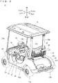
Fig. 1 is a side view (taken from left) showing a golf car or golf cart according to an embodiment of the present invention. -
Fig. 2 is a rear perspective view showing the golf car according to the embodiment of the present invention. -
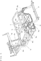
Fig. 3 is a rear perspective view showing primary part of a frame portion. -
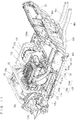
Fig. 4 is a rear perspective view showing part of the frame portion, a transmission and their surroundings. -
Fig. 5 is a rear perspective view showing primary part of the frame portion and a front cover portion. -
Fig. 6 is a perspective view showing the frame portion and its surroundings. -
Fig. 7 is a perspective view showing the frame portion, an undercover and their surroundings. -
Fig. 8 is a rear perspective view showing the frame portion, a floor panel, and so on. -
Fig. 9 is a plan view showing the frame portion, the floor panel, and so on. -
Fig. 10(a) is an enlarged view showing an opening;Fig. 10 (b) is an enlarged view showing a platy member; andFig. 10(c) is an enlarged view showing a cover portion. -
Fig. 11 is a front perspective view showing primary part of the golf car. -
Fig. 12 is a front perspective view showing primary part of the golf car. -
Fig. 13 is a rear perspective view showing primary part of the golf car. -
Fig. 14 is a plan view showing primary part of the golf car. -
Fig. 15 is a side view (taken from left) showing the frame portion, the floor panel, and so on. -
Fig. 16 is a side view (taken from right) showing the frame portion, a groove portion and so on, under a state where part of the floor panel on a more right side than the groove portion is removed. -
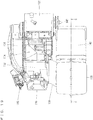
Fig. 17 is a front view with a partial section taken along a line A-A inFig. 15 to show an engine, a muffler and their surroundings. -
Fig. 18 is a plan view with a partial section taken along a line B-B inFig. 15 to show the engine, the muffler and their surroundings. -
Fig. 19 is a plan view showing the engine, a muffler cover and their surroundings. -
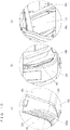
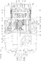
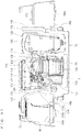
Fig. 20 is a front perspective view showing the engine, the muffler cover and their surroundings. -
Fig. 21 is a rear perspective view showing the engine, the muffler cover and their surroundings. -
Fig. 22 is a side view with a partial section taken in a line C-C inFig. 19 to show the muffler, the muffler cover, an exhaust duct and their surroundings. -
Fig. 23 is a side view with a partial section, to show the muffler, the muffler cover and the exhaust duct. -
Fig. 24 is an illustrative sectional drawing showing the exhaust duct and its surroundings. -
Fig. 25 is an illustrative sectional drawing showing a primary part in an embodiment including an open/close member and a cooling hole. -
Fig. 26 shows the open/close member, a holding member and so on viewed from the direction of Arrow D (seeFig. 25 ), in a state where the open/close member is opened. -
Fig. 27 shows the exhaust duct, the open/close member, the holding member and so on viewed from the direction of Arrow E (seeFig. 25 ), in a state where the open/close member is closed. -
Fig. 28 shows the exhaust duct, the cooling hole, the holding member and so on viewed from the direction of Arrow F (seeFig. 25 ). -
Fig. 29(a) is an illustrative drawing showing a flow of exhaust gas in the state where the open/close member is opened;Fig. 29(b) is an illustrative drawing showing sound pressure changes and a direction in which exhaust heat is directed, under the state where the open/close member is closed. - Hereinafter, embodiments of the present invention will be described with reference to the drawings. Herein, description will be made for a case where the present invention is applied to a
golf car 10 as an example of a vehicle. It is noted that the terms front and rear, right and left, up and down as used in the following description are determined from the golf car driver's position on aseat portion 18 of thegolf car 10, with the driver facing toward asteering wheel 30. - Referring to
Fig. 1 andFig. 2 , thegolf car 10 is a two-person golf car, and includes a pair offront wheels Fig. 9 ), a pair ofrear wheels frame portion 16. The pair ofrear wheels front wheels front wheels frame portion 16. The pair ofrear wheels frame portion 16. - The
seat portion 18 extends in a width direction of thegolf car 10 at a more rearward position than the pair offront wheels rear wheels seat portion 18 is supported by a seat rail 72 (which will be described later) of theframe portion 16. A seat back 20 is provided at an obliquely upward and rearward position of theseat portion 18. Abasket 22 for accommodating baggage is provided behind the seat back 20. The seat back 20 and thebasket 22 are supported byrear pillars - A pair of
front pillars seat portion 18, whereas a pair ofrear pillars seat portion 18. Thefront pillars rear pillars frame portion 16 at their lower end portions. Thefront pillars rear pillars roof portion 28 covers above theseat portion 18, and is supported by thefront pillars rear pillars - A
steering wheel 30 is located ahead of the seat back 20. Thesteering wheel 30 is connected to thefront wheels steering shaft 32 and an unillustrated connection mechanism. - The
frame portion 16 is covered with acowl 34, a pair ofside protectors 36, afloor panel 38, abody panel 39, a pair of rear fender covers 40a, 40b and arear floor cover 42, each made of a resin for example. Thecowl 34 covers the front region of theframe portion 16 and above thefront wheels side protectors 36 covers an intermediate region of theframe portion 16 from two sides. Thefloor panel 38, which functions as a footrest for the driver and the passenger sitting on theseat portion 18 to rest their feet, provides a bottom portion of a cabin space of thegolf car 10. Thebody panel 39 covers a front region below theseat portion 18. The pair of rear fender covers 40a, 40b cover two sides below theseat portion 18 and above the pair ofrear wheels rear floor cover 42 is sandwiched by rear end portions of the pair of rear fender covers 40a, 40b, and has aconcave portion 42a for placement of golf bags for example. By only removing therear floor cover 42, it becomes possible to easily maintain a CVT (Continuously Variable Transmission) 144 (which will be described later) and a transmission 146 (which will be described later). At a position above theconcave portion 42a and behind thebasket 22, there is provided a holdingportion 44 for holding the golf bags. The holdingportion 44 is supported by connectingmembers - Next, description will cover a structure of the
frame portion 16 and its surroundings. - Referring to
Fig. 3 through Fig. 7 , theframe portion 16 includes a pair ofmain frames cross members support frames main frames front frames rear frames respective front frames front frames rear frames - The
front frames cross members front frame 48a and therear frame 50a are joined to each other and a portion where thefront frame 48b and therear frame 50b are joined to each other are connected to each other by thecross member 56. Therear frames cross member 58. In other words, themain frames cross members cross members cross member 52 is joined to the pair ofsupport frames - The pair of
support frames cross member 62 which extends in the vehicle's width direction. Near thecross member 54 in the pair offront frames support frames rear frames connection frame 66. The pair ofrear frames connection frame 68. Theconnection frame 66 extends in the vehicle's width direction, with its two end portions extending downward, to provide an upward projecting substantially U shape . Theconnection frame 68 extends in the vehicle's width direction, with its two end portions extending downward, to provide an upward projecting substantially U shape. The connection frames 66 and 68 are spaced apart from each other in the vehicle's fore-aft direction, and are connected to each other by the connectingmembers support frames connection frame 66 have two side portions; and these portions are connected to each other by theseat rail 72. Theseat rail 72 is formed substantially in a C shape extending in a horizontal direction. To thecross member 54, a pair ofbrackets - Referring to
Fig. 4 , a pair ofengine brackets brackets engine brackets cross member 78. Thecross member 78 is joined to asupport frame 79 which extends forward andsupport frames support frame 79 has its tip portion formed with aprojection 79a. The support frames 80a, 80b have their respective rear end portions formed with through-holes Fig. 8 ) . On thecross member 78 and the support frames 80a, 80b, there is attached anengine bracket 84 for supporting an engine 114 (which will be described later) . Thecross member 78 is joined to theengine brackets engine bracket 84 is also pivotable in the up-down direction. Thecross member 56 is joined to a pair offrames frames cross member 88. The pair offrames cross member 58. - Referring to
Fig. 6 andFig. 7 , theframe portion 16 supports an undercover 90. The undercover 90 has afront cover portion 92 and arear cover portion 94 respectively on its forward and rearward sides. Thefront cover portion 92 is located between thecross members front frames cross members rear cover portion 94 is located between thecross members cross members frames rear frames rear frames inner cowls 95 is placed between therear wheels rear wheels - The undercover 90, the
seat portion 18, thebody panel 39, a heat insulation board 176 (which will be described later), a fuel tank 168 (which will be described later), the left and the rightinner cowls 95 and therear floor cover 42 define a space as an engine room S. In other words, the engine room S is surrounded by the undercover 90, theseat portion 18, thebody panel 39, theheat insulation board 176, thefuel tank 168, the left and the rightinner cowls 95 and therear floor cover 42. In other words, on an under side, an upper side, a front side, a left side, a right side and a rear side of the engine room S, there are provided the undercover 90, theseat portion 18, thebody panel 39, theheat insulation board 176 and the leftinner cowl 95, thefuel tank 168 and the rightinner cowl 95, and the rear floor cover 42 respectively. The undercover 90 is provided at a lower place than theengine 114, and defines an under side of the engine room S. As described, the engine room S is surrounded with the undercover 90, theseat portion 18, thebody panel 39, theheat insulation board 176, thefuel tank 168, the left and the rightinner cowls 95 and therear floor cover 42, whereby it is possible to reduce leakage of noise of the engine room S to outside of the engine room S. - Referring to
Fig. 8 andFig. 9 , thefloor panel 38 is placed on thefront frames cross member 62 of the above-describedframe portion 16. Thefloor panel 38 is placed between the pair offront wheels rear wheels floor panel 38 includes a panelmain body 96, anopening 98 and agroove portion 100. The panelmain body 96 includes afirst panel portion 102 extending substantially horizontally in the fore-aft direction between thefront wheels rear wheels second panel portion 104 placed behind thefront wheels first panel portion 102; andthird panel portions first panel portion 102. Thefirst panel portion 102 is located ahead of the engine room S; thethird panel portion 106a is located on the left side of the engine room S; and thethird panel portion 106b is located on the right side of the engine room S. Preferably, thesecond panel portion 104 rises obliquely forward from the front end region of thefirst panel portion 102. Theopening 98 is located at a front region of the panelmain body 96, i.e., in the second panel portion 104 (seeFig. 10(a)). Fig. 10(a) shows theopening 98 with hatching. Thegroove portion 100 communicates with theopening 98 in order to supply external air which is introduced from theopening 98 into a shroud 132 (which will be described later) and into theengine 114, is placed on an upper surface of the panelmain body 96, and extends in a fore-aft direction of the panelmain body 96. Thegroove portion 100 is continuous from thesecond panel portion 104 to thefirst panel portion 102, provides communication between theopening 98 and the engine room S, and is capable of introducing a running wind from ahead of thegolf car 10 to the engine room S. In the present embodiment, thegroove portion 100 is formed on a slightly righter side than the center, in the vehicle's width direction. Theopening 98 is placed in aside surface 100a of thegroove portion 100. Referring toFig. 10(a) and Fig. 10(b) , aplaty member 108, which protrudes forward from a reverse surface (front surface) of thesecond panel portion 104, is provided on a side of theopening 98. Also, referring toFig. 10(c) , a rectangular plate-like cover portion 110, which is supported by theframe portion 16, is provided ahead of theopening 98. Further, thegroove portion 100 is covered by a lid portion 112 (seeFig. 8 ). Thelid portion 112 is provided by a strip-like platy member formed to a longitudinal shape of thegroove portion 100. - Referring to
Fig. 11 through Fig. 17 , inside the engine room S, theengine bracket 84 supports theengine 114. Theengine 114 is an air-cooled engine which provides a single-cylinder, for example. Theengine 114 provides afuel injection device 115 which injects fuel into anair intake tube 126. Theengine 114 is placed behind thefirst panel portion 102 of thefloor panel 38, and includes acylinder head 116, acylinder body 118 and a crankcase 120. Theengine 114 is tilted forward. Anair cleaner 122 is provided above theengine 114. Theair cleaner 122 is joined to anair intake duct 124 via a joint 123. Theair intake duct 124 is located on the right side of theair cleaner 122, and includes a cylindricalfront duct 124a and a noise-reducingrear duct 124b of a flattened shape. A rear end portion of thefront duct 124a and a front end portion of therear duct 124b are joined to each other. In order to introduce the external air from thegroove portion 100, thefront duct 124a is disposed to face thegroove portion 100 from the engine room S, and a rear end portion of therear duct 124b is joined to the joint 123. Thus, theair intake duct 124 and theair cleaner 122 communicate with each other. As indicated by Arrow X inFig. 16 , the external air, which is introduced from ahead and comes through theopening 98 and into thegroove portion 100, is then introduced into theair cleaner 122 from thegroove portion 100 via theair intake duct 124. Then, after being cleaned by theair cleaner 122, the air is supplied, via theair intake tube 126, into theengine 114. As understood, theair cleaner 122 is provided between theair intake duct 124 and theengine 114. Inside the engine room S, amuffler 128 is provided adjacently on a side (on the left side in the present embodiment) of theengine 114. Theengine 114 and themuffler 128 are joined to each other via anexhaust pipe 130. Exhaust gas from theengine 114 is supplied to themuffler 128 via theexhaust pipe 130. - The
cylinder body 118 of theengine 114 is covered by theshroud 132, with an air-flowable gap between thecylinder body 118 and theshroud 132. Afan case 134 is provided on a side surface (on the right side surface in the present embodiment) of theengine 114. Theshroud 132 and thefan case 134 are connected to each other. Inside thefan case 134, there is provided afan 136 for supplying the external air from thegroove portion 100 into the shroud 132 (between theshroud 132 and the engine 114). Thefan 136 is preferably connected to a crank shaft 142 (seeFig. 18 ) and driven thereby. Also, themuffler 128 is covered by amuffler cover 138 so that an air-flowable gap is formed between themuffler 128 and themuffler cover 138. Theshroud 132 and themuffler cover 138 communicate with each other via aduct 139 which covers theexhaust pipe 130. It should be noted here thatFig. 11 ,Fig. 12 ,Fig. 20 andFig. 21 do not show theduct 139. Anexhaust duct 140 is connected to an exit end portion of themuffler cover 138. Theexhaust duct 140 has its rear end portion exposed to the outside from anopening 92a of the front cover portion 92 (seeFig. 7 ,Fig. 20 andFig. 22 ) . Themuffler cover 138 is supported by the support frame 79 (seeFig. 4 andFig. 11 ), as theprojection 79a of thesupport frame 79 is inserted through ahole 141a of abracket 141 attached on a side surface of themuffler cover 138. As indicated by Arrow Y inFig. 17 andFig. 18 , the external air which is introduced into theshroud 132 by thefan 136 flows between theshroud 132 and the engine 114 (the cylinder body 118), into the muffler cover 138 (between themuffler cover 138 and the muffler 128), and serves as a cooling wind to cool theengine 114 and themuffler 128. Then, the air inside themuffler cover 138 flows through theexhaust duct 140 and is discharged from theopening 92a of thefront cover portion 92, to the outside, below the engine room S. Themuffler 128, themuffler cover 138, theexhaust duct 140 and their surroundings will be described later. - Referring also to
Fig. 18 through Fig. 21 , an output from thecrank shaft 142 of theengine 114 is transmitted via the CVT (Continuously Variable Transmission) 144 to thetransmission 146. TheCVT 144 is located behind themuffler 128, whereas thetransmission 146 is located behind theengine 114, between the pair ofrear wheels - The
engine 114, themuffler 128, theshroud 132, themuffler cover 138, theexhaust duct 140, theCVT 144 and thetransmission 146 described above are housed in the engine room S. - Referring also to
Fig. 4 , thetransmission 146 is joined to a pair ofrotation transmission portions rotation transmission portion 148a extends to the left of thetransmission 146, and includes a constant-velocity joint 150a, adrive shaft 152a, a constant-velocity joint 154a and anaxle 156a. Thetransmission 146 has its output shaft (not illustrated) connected to thedrive shaft 152a by the constant-velocity joint 150a, whereas thedrive shaft 152a and theaxle 156a are connected to each other by the constant-velocity joint 154a. Therotation transmission portion 148b extends to the right of thetransmission 146, and includes a constant-velocity joint 150b, adrive shaft 152b, a constant-velocity joint 154b and anaxle 156b. Thetransmission 146 has its output shaft connected to thedrive shaft 152b by the constant-velocity joint 150b, whereas thedrive shaft 152b and theaxle 156b are connected to each other by the constant-velocity joint 154b. Theaxle 156a supports therear wheel 14a, whereas theaxle 156b supports therear wheel 14b. It should be noted here that the through-hole 82a at the rear end portion of thesupport frame 80a is penetrated by the output shaft of thetransmission 146 between thetransmission 146 and the constant-velocity joint 150a, whereas the through-hole 82b at the rear end portion of thesupport frame 80b is penetrated by the output shaft of thetransmission 146 between thetransmission 146 and the constant-velocity joint 150b (seeFig. 13 ). - Also, the pair of
rear wheels suspensions suspensions suspensions knuckles arms shock absorbers knuckle 160a supports theaxle 156a rotatably. Thearm 162a connects a lower portion of theknuckle 160a and theframe 86a to each other. Theshock absorber 164a has a lower end portion and an upper end portion, respectively joined to an upper end portion of theknuckle 160a and to theconnection frame 68. Likewise, theknuckle 160b supports theaxle 156b rotatably. Thearm 162b connects a lower portion of theknuckle 160b and theframe 86b to each other. Theshock absorber 164b has a lower end portion and an upper end portion, respectively joined to an upper end portion of theknuckle 160b and to theconnection frame 68. - Referring to
Fig. 12 , the pair offront wheels suspensions frame portion 16. In the present embodiment, the pair ofsuspensions - Referring to
Fig. 14 andFig. 17 , thefuel tank 168 is placed on the right side of theengine 114 and on thethird panel portion 106b of thefloor panel 38. Between theengine 114 and thefuel tank 168, asound absorbing member 170 is erected and attached to a side surface of thefuel tank 168. Also, abattery 172 is placed on the left of themuffler cover 138 and on thethird panel portion 106a of thefloor panel 38. Between themuffler cover 138 and thebattery 172, a two-ply structure made of asound absorbing member 174 and theheat insulation board 176 is erected. It is possible, with thesound absorbing members heat insulation board 176, to reduce heat conducting from the engine room S to thebattery 172. - Referring also to
Fig. 22 through Fig. 24 , themuffler 128, themuffler cover 138, theexhaust duct 140 and their surroundings will be described. - The
muffler 128 has anexpansion chamber 178 at its rear portion, which is stuffed with a sound absorbing material such as glass wool for example. Theexpansion chamber 178 reduces exhaust gas noise. Theexpansion chamber 178 is provided with adischarge pipe 180 extending obliquely rearward and downward. In other words, themuffler 128 has an outlet (where exhaust gas is discharged), at which thedischarge pipe 180 is provided. Thedischarge pipe 180 has a rearward end portion, at which ajoint exhaust 182 is attached. - The
joint exhaust 182 includes asilencer 184, aseal member 186, a holding member 188, a cap member 190 and a fastener 192. Thesilencer 184 is made of a stainless steel mesh member for example, is provided at the outlet of themuffler 128 via thedischarge pipe 180, reduces thrust of the exhaust gas, and alters sound quality of the exhaust gas noise. Theseal member 186 is hollow cylindrical, and is fitted around a rearward end portion of thedischarge pipe 180. The cylindrical holding member 188 and the annular cap member 190 are formed integrally with each other, and hold thesilencer 184 and theseal member 186. The fastener 192 is fitted around an outer circumferential surface of the holding member 188 to tighten the holding member 188 so that the holding member 188 presses thesilencer 184 and theseal member 186 radially inward. - The
muffler cover 138 is made of a resin for example, provided with an insulation member (not illustrated) on its inner surface, and formed to have a generally rectangular tubular upper portion and a generally cylindrical lower portion (seeFig. 20 andFig. 21 ). - The
exhaust duct 140 is made of rubber, for example, is elastic and formed into a flattened shape (seeFig. 20 andFig. 21 ). In order to discharge the exhaust gas from below the engine room S to the outside, theexhaust duct 140 extends rearward above the undercover 90 (the front cover portion 92), so that a rearward end portion of theexhaust duct 140 is positioned at theopening 92a of thefront cover portion 92 and is fitted into theopening 92a. Theopening 92a is located at a more rearward position than themuffler 128 in a side view. Also, theopening 92a is located at a more rearward position than themuffler cover 138 in a side view. Theexhaust duct 140 hasrecesses exhaust duct 140 corresponding to therecesses Fig. 6 andFig. 21 ) . Sound absorbingmembers recesses sound absorbing member 200 is arranged on the inner circumferential surface of theexhaust duct 140 on an extended line of a center axis P of thedischarge pipe 180 which is provided at the outlet of themuffler 128. Thesound absorbing member 202 is arranged to be hit by exhaust gas after the gas is bounced by thesound absorbing member 200. Preferably, thesound absorbing members sound absorbing members exhaust duct 140, holdingmembers exhaust duct 140. The holdingmembers sound absorbing members fasteners members members Fig. 24 , noise of the exhaust gas emitted from thedischarge pipe 180 of themuffler 128 into theexhaust duct 140 is reflected and absorbed by thesound absorbing members Fig. 24 , thicknesses of the white arrows indicate sound pressures, to show that exhaust gas noise is gradually attenuated. - According to the
golf car 10 as has been described, theexhaust duct 140 which is connected to the exit end portion of themuffler cover 138 extends rearward above the undercover 90 that is provided at a lower position than theengine 114, whereas theexhaust duct 140 has its rearward end portion positioned at theopening 92a which is located at a more rearward position than themuffler 128 in a side view. Exhaust gas from themuffler 128 passes through theexhaust duct 140 and theopening 92a of the undercover 90 (front cover portion 92), and is discharged from below the engine room S to the outside. Since theexhaust duct 140 extends rearward so that the rearward end portion of theexhaust duct 140 is located at a more rearward position than themuffler 128, noise from themuffler 128 is attenuated inside theexhaust duct 140. Also, since theexhaust duct 140 is connected to themuffler cover 138, the cooling wind from themuffler cover 138 passes through theexhaust duct 140 and is discharged from theopening 92a, and noise propagating through themuffler cover 138, such as vibration noise of theengine 114, is attenuated inside theexhaust duct 140. Therefore, it is possible to reduce noise leakage out of the vehicle. - Since the
exhaust duct 140 is elastic and is capable of absorbing vertical movements of themuffler cover 138, it is possible to stably position the rearward end portion of theexhaust duct 140 at theopening 92a of the undercover 90. - Since the
exhaust duct 140 is fitted into theopening 92a, it is easy to position and attach theexhaust duct 140. - The
silencer 184 makes it possible to further attenuate the noise from themuffler 128, and thereby further reduce noise leakage out of the vehicle. - The exhaust gas noise emitted from the
muffler 128 is attenuated by thesound absorbing members exhaust duct 140. The arrangement further reduces noise leakage out of the vehicle. - Since the
sound absorbing members exhaust duct 140, the arrangement makes it possible to reduce costs. - The holding
members sound absorbing members exhaust duct 140. - The arrangement that the holding
members sound absorbing members exhaust duct 140 while maintaining the sound absorbing capabilities of thesound absorbing members - It should be noted here that sound absorbing members may be attached to the
seat portion 18, thebody panel 39, therear floor cover 42, the undercover 90 and the left and the rightinner cowls 95. - Also, the
exhaust duct 140 may be replaced with anexhaust duct 140a shown inFig. 25 , with an open/close member 212 provided inside theexhaust duct 140a. Theexhaust duct 140a is identical with theexhaust duct 140 except that it has a cooling hole 220 (which will be described later). The open/close member 212 is configured in such a way that it can be opened when thegolf car 10 is moving and it can be closed when thegolf car 10 stops. In the present embodiment, the open/close member 212 is configured in such a fashion that it is opened by exhaust gas which passes through theexhaust duct 140a, and it is closed by gravity (own weight) of the open/close member 212. An amount of opening (an extent of opening) of the open/close member 212 is set in accordance with exhaust gas pressure received by the open/close member 212.Fig. 25 shows a closed state of the open/close member 212 indicated in a solid line and a fully opened state of the open/close member 212 indicated in an alternate long and short dash line. As the exhaust gas pressure (amount of exhaust gas) increases, the degree of opening of the open/close member 212 increases. - Referring to
Fig. 25 through Fig. 27 , the open/close member 212 is provided by, for example, a stainless steel exhaust gas flap of a slightly curved plate. The open/close member 212, is joined, at a widthwise intermediate region of its end portion (upper end portion), to a widthwise intermediate region of an end portion (upper end portion) of the holdingmember 206 via ahinge 214 made of stainless steel for example. The open/close member 212 and thehinge 214 are connected to each other with afastener 216, whereas the holdingmember 206 and thehinge 214 are connected to each other with afastener 218. The open/close member 212 is made wider than the holdingmember 206. The open/close member 212 is openable/closable (pivotable) around thehinge 214. The open/close member 212 is provided near theopening 92a where the rearward end portion of theexhaust duct 140a is located. - Referring also to
Fig. 28 , in theexhaust duct 140a, acooling hole 220 penetrates an inner circumferential surface and an outer circumferential surface (an upper surface corresponding to therecess 198 in the present embodiment) of theexhaust duct 140a on a more downstream side than but near the open/close member 212 in its closed state. Thecooling hole 220 is formed above theopening 92a where the rearward end portion of theexhaust duct 140a is located. Asound absorbing member 202a, in which portions corresponding to thecooling hole 220 is removed, is fitted into therecess 198 of theexhaust duct 140a. Therefore, the holdingmember 206 is exposed to the outside in thecooling hole 220. - According to this embodiment, when the
golf car 10 is moving, the open/close member 212 opens, thereby enabling exhaust gas from themuffler 128 to discharge smoothly to the outside from below the engine room S via theexhaust duct 140a and theopening 92a of the undercover 90, as indicated inFig. 29(a) with a white arrow G. On the other hand, when thegolf car 10 is stopped, the open/close member 212 closes, whereby it is possible to further attenuate noises such as noise from themuffler 128 and vibration noise of theengine 114 which propagates through themuffler cover 138, in theexhaust duct 140a, as indicated inFig. 29(b) with a white arrow H1, and therefore to further reduce noise leakage out of the vehicle. It should be noted here that the thicknesses of the white arrow H1 indicate sound pressures. - Since the open/
close member 212 is configured to be opened by the exhaust gas which passes through theexhaust duct 140a, there is no need for providing any separate parts for opening the open/close member 212, yet it is possible to open the open/close member 212. - When the
engine 114 is running at a slow speed (e.g., not greater than 2500 rpm), exhaust gas pressure (amount of exhaust gas) is small and the open/close member 212 is half open, so it is possible to achieve both discharging of the exhaust gas and reducing noise leakage to the outside of the vehicle. The arrangement is particularly effective when thegolf car 10 is traveling at a constant speed. - When the
golf car 10 is stopped and the open/close member 212 is closed, heat at the open/close member 212 is released through thecooling hole 220 to the outside (above, in the present embodiment) theexhaust duct 140a as indicated inFig. 29(b) with an arrow H2, whereby the arrangement is capable of cooling the open/close member 212 and therefore reducing deterioration of the open/close member 212 due to heat. - It should be noted here that although the open/
close member 212 is configured to be closed by its own weight in the embodiment shown inFig. 25 , the invention is not limited to this. The open/close member 212 may be configured to be closed by an elastic member such as a spring. - In the embodiment described thus far, description was made for a case where the present invention is applied to a golf car. However, the present invention is not limited to this. The present invention is applicable to any other vehicles.
- The present invention being thus far described in terms of preferred embodiments, it is obvious that these may be varied in many ways within the scope and the spirit of the present invention. The scope of the present invention is only limited by the accompanied claims.
-
- 10 Golf car
- 90 Undercover
- 92 Front cover portion
- 92a, 98 Openings
- 114 Engine
- 118 Cylinder body
- 128 Muffler
- 132 Shroud
- 138 Muffler cover
- 140, 140a Exhaust ducts
- 184 Silencer
- 200, 202, 202a Sound absorbing members
- 204, 206 Holding members
- 212 Open/close member
- 220 Cooling hole
- S Engine room
Claims (11)
- A vehicle comprising:an engine including a cylinder body;a muffler to which exhaust gas from the engine is supplied;a shroud covering the cylinder body;a muffler cover covering the muffler and communicating with the shroud;an undercover provided at a lower position than the engine and having an opening;an exhaust duct connected to an exit end portion of the muffler cover; andan engine room having an underside defined by the undercover, and which houses the engine, the muffler, the shroud, the muffler cover and the exhaust duct, whereinthe opening is located at a more rearward position than the muffler in a side view, andthe exhaust duct is routed above the undercover and the exhaust duct has its rearward end portion positioned at the opening in order to discharge the exhaust gas from below the engine room to the outside.
- The vehicle according to Claim 1, wherein the exhaust duct is elastic.
- The vehicle according to Claim 1 or 2, wherein the exhaust duct is fitted to the opening.
- The vehicle according to one of Claims 1 through 3, further comprising a silencer provided at an outlet of the muffler.
- The vehicle according to one of Claims 1 through 4, further comprising a sound absorbing member provided on an inner circumferential surface of the exhaust duct.
- The vehicle according to Claim 5, further comprising a discharge pipe provided at an outlet of the muffler,
wherein the sound absorbing member is in the exhaust duct, on an extended line of a center axis of the discharge pipe. - The vehicle according to Claim 5 or 6, further comprising a holding member for holding the sound absorbing member on the inner circumferential surface of the exhaust duct, wherein the holding member is provided by a perforated plate.
- The vehicle according to Claim 1, further comprising an open/close member provided inside the exhaust duct,
wherein the open/close member is configured to be opened when the vehicle is traveling and closed when the vehicle is stopped. - The vehicle according to Claim 8, wherein the open/close member is configured to be opened by the exhaust gas passing through the exhaust duct.
- The vehicle according to Claim 9, wherein the open/close member is opened to an amount in accordance with an exhaust gas pressure received by the open/close member.
- The vehicle according to one of Claims 8 through 10, further comprising a cooling hole provided in the exhaust duct,
wherein the cooling hole penetrates an inner circumferential surface and an outer circumferential surface of the exhaust duct on a more downstream side than the open/close member but near the open/close member in its closed state.
Applications Claiming Priority (3)
| Application Number | Priority Date | Filing Date | Title |
|---|---|---|---|
| JP2016136457 | 2016-07-08 | ||
| JP2017108116A JP6338739B2 (en) | 2016-07-08 | 2017-05-31 | vehicle |
| PCT/JP2017/023184 WO2018008432A1 (en) | 2016-07-08 | 2017-06-23 | Vehicle |
Publications (3)
| Publication Number | Publication Date |
|---|---|
| EP3482990A1 true EP3482990A1 (en) | 2019-05-15 |
| EP3482990A4 EP3482990A4 (en) | 2020-03-11 |
| EP3482990B1 EP3482990B1 (en) | 2022-05-04 |
Family
ID=60912631
Family Applications (1)
| Application Number | Title | Priority Date | Filing Date |
|---|---|---|---|
| EP17824039.6A Active EP3482990B1 (en) | 2016-07-08 | 2017-06-23 | Vehicle |
Country Status (2)
| Country | Link |
|---|---|
| EP (1) | EP3482990B1 (en) |
| WO (1) | WO2018008432A1 (en) |
Families Citing this family (1)
| Publication number | Priority date | Publication date | Assignee | Title |
|---|---|---|---|---|
| CN115434797B (en) * | 2022-09-26 | 2024-03-26 | 无锡宝顺不锈钢有限公司 | Stainless steel belt for automobile exhaust system |
Family Cites Families (7)
| Publication number | Priority date | Publication date | Assignee | Title |
|---|---|---|---|---|
| JPH07215074A (en) * | 1994-02-07 | 1995-08-15 | Toyota Motor Corp | Under-cover device for vehicle |
| JP3414518B2 (en) * | 1994-09-21 | 2003-06-09 | 本田技研工業株式会社 | Cooling structure of vehicle engine room |
| JP2005007995A (en) | 2003-06-18 | 2005-01-13 | Yamaha Motor Co Ltd | Small vehicle |
| JP5733335B2 (en) * | 2013-04-19 | 2015-06-10 | コベルコ建機株式会社 | Exhaust structure of construction machinery |
| JP6289246B2 (en) * | 2014-04-24 | 2018-03-07 | 本田技研工業株式会社 | Diluter |
| JP2016008599A (en) * | 2014-06-26 | 2016-01-18 | ヤマハ発動機株式会社 | Muffler unit and vehicle equipped with the same |
| JP2016185749A (en) * | 2015-03-27 | 2016-10-27 | 愛三工業株式会社 | Engine intake system for vehicle |
-
2017
- 2017-06-23 EP EP17824039.6A patent/EP3482990B1/en active Active
- 2017-06-23 WO PCT/JP2017/023184 patent/WO2018008432A1/en unknown
Also Published As
| Publication number | Publication date |
|---|---|
| WO2018008432A1 (en) | 2018-01-11 |
| EP3482990B1 (en) | 2022-05-04 |
| EP3482990A4 (en) | 2020-03-11 |
Similar Documents
| Publication | Publication Date | Title |
|---|---|---|
| US7699134B2 (en) | Motorcycle exhaust system | |
| US10406903B2 (en) | Vehicle | |
| JP4991464B2 (en) | Motorcycle | |
| US20100213000A1 (en) | Vehicular muffler and motorcycle incorporating same | |
| JP2007269150A (en) | Air-intake structure of seat-type vehicle | |
| ZA200804461B (en) | Motorcycle including a rider saddle and a fuel tank | |
| AU2017292285B2 (en) | Vehicle | |
| EP3482990B1 (en) | Vehicle | |
| CN102996296B (en) | Motorcycle | |
| AU2017292238B2 (en) | Vehicle | |
| JP3999471B2 (en) | Motorcycle front cowl support structure | |
| JP5778947B2 (en) | Exhaust gas purification device for saddle-ride type vehicles | |
| CN101062655B (en) | Vehicle air intake box arrangement structure | |
| JP2008179341A (en) | Motorcycle | |
| JP3770473B2 (en) | Motorcycle cooling structure | |
| JP5979380B2 (en) | Intake sound transmission device for vehicle | |
| JP2021160655A (en) | Lower body structure of vehicle | |
| JPH06144019A (en) | Driving system arranging structure for vehicle | |
| JPH05104939A (en) | Automotive rear part structure | |
| JPH0616053A (en) | Scavenging fan mounting structure for engine room |
Legal Events
| Date | Code | Title | Description |
|---|---|---|---|
| STAA | Information on the status of an ep patent application or granted ep patent |
Free format text: STATUS: THE INTERNATIONAL PUBLICATION HAS BEEN MADE |
|
| PUAI | Public reference made under article 153(3) epc to a published international application that has entered the european phase |
Free format text: ORIGINAL CODE: 0009012 |
|
| STAA | Information on the status of an ep patent application or granted ep patent |
Free format text: STATUS: REQUEST FOR EXAMINATION WAS MADE |
|
| 17P | Request for examination filed |
Effective date: 20181129 |
|
| AK | Designated contracting states |
Kind code of ref document: A1 Designated state(s): AL AT BE BG CH CY CZ DE DK EE ES FI FR GB GR HR HU IE IS IT LI LT LU LV MC MK MT NL NO PL PT RO RS SE SI SK SM TR |
|
| AX | Request for extension of the european patent |
Extension state: BA ME |
|
| DAV | Request for validation of the european patent (deleted) | ||
| DAX | Request for extension of the european patent (deleted) | ||
| A4 | Supplementary search report drawn up and despatched |
Effective date: 20200206 |
|
| RIC1 | Information provided on ipc code assigned before grant |
Ipc: F01N 13/20 20100101ALI20200131BHEP Ipc: F01N 1/24 20060101ALI20200131BHEP Ipc: B60K 13/04 20060101AFI20200131BHEP Ipc: F01N 1/00 20060101ALI20200131BHEP |
|
| STAA | Information on the status of an ep patent application or granted ep patent |
Free format text: STATUS: EXAMINATION IS IN PROGRESS |
|
| 17Q | First examination report despatched |
Effective date: 20210625 |
|
| STAA | Information on the status of an ep patent application or granted ep patent |
Free format text: STATUS: EXAMINATION IS IN PROGRESS |
|
| GRAP | Despatch of communication of intention to grant a patent |
Free format text: ORIGINAL CODE: EPIDOSNIGR1 |
|
| STAA | Information on the status of an ep patent application or granted ep patent |
Free format text: STATUS: GRANT OF PATENT IS INTENDED |
|
| INTG | Intention to grant announced |
Effective date: 20211221 |
|
| GRAS | Grant fee paid |
Free format text: ORIGINAL CODE: EPIDOSNIGR3 |
|
| GRAA | (expected) grant |
Free format text: ORIGINAL CODE: 0009210 |
|
| STAA | Information on the status of an ep patent application or granted ep patent |
Free format text: STATUS: THE PATENT HAS BEEN GRANTED |
|
| AK | Designated contracting states |
Kind code of ref document: B1 Designated state(s): AL AT BE BG CH CY CZ DE DK EE ES FI FR GB GR HR HU IE IS IT LI LT LU LV MC MK MT NL NO PL PT RO RS SE SI SK SM TR |
|
| REG | Reference to a national code |
Ref country code: GB Ref legal event code: FG4D |
|
| REG | Reference to a national code |
Ref country code: CH Ref legal event code: EP |
|
| REG | Reference to a national code |
Ref country code: AT Ref legal event code: REF Ref document number: 1488686 Country of ref document: AT Kind code of ref document: T Effective date: 20220515 |
|
| REG | Reference to a national code |
Ref country code: DE Ref legal event code: R096 Ref document number: 602017057040 Country of ref document: DE |
|
| REG | Reference to a national code |
Ref country code: IE Ref legal event code: FG4D |
|
| REG | Reference to a national code |
Ref country code: LT Ref legal event code: MG9D |
|
| REG | Reference to a national code |
Ref country code: NL Ref legal event code: MP Effective date: 20220504 |
|
| REG | Reference to a national code |
Ref country code: AT Ref legal event code: MK05 Ref document number: 1488686 Country of ref document: AT Kind code of ref document: T Effective date: 20220504 |
|
| PG25 | Lapsed in a contracting state [announced via postgrant information from national office to epo] |
Ref country code: SE Free format text: LAPSE BECAUSE OF FAILURE TO SUBMIT A TRANSLATION OF THE DESCRIPTION OR TO PAY THE FEE WITHIN THE PRESCRIBED TIME-LIMIT Effective date: 20220504 Ref country code: PT Free format text: LAPSE BECAUSE OF FAILURE TO SUBMIT A TRANSLATION OF THE DESCRIPTION OR TO PAY THE FEE WITHIN THE PRESCRIBED TIME-LIMIT Effective date: 20220905 Ref country code: NO Free format text: LAPSE BECAUSE OF FAILURE TO SUBMIT A TRANSLATION OF THE DESCRIPTION OR TO PAY THE FEE WITHIN THE PRESCRIBED TIME-LIMIT Effective date: 20220804 Ref country code: NL Free format text: LAPSE BECAUSE OF FAILURE TO SUBMIT A TRANSLATION OF THE DESCRIPTION OR TO PAY THE FEE WITHIN THE PRESCRIBED TIME-LIMIT Effective date: 20220504 Ref country code: LT Free format text: LAPSE BECAUSE OF FAILURE TO SUBMIT A TRANSLATION OF THE DESCRIPTION OR TO PAY THE FEE WITHIN THE PRESCRIBED TIME-LIMIT Effective date: 20220504 Ref country code: HR Free format text: LAPSE BECAUSE OF FAILURE TO SUBMIT A TRANSLATION OF THE DESCRIPTION OR TO PAY THE FEE WITHIN THE PRESCRIBED TIME-LIMIT Effective date: 20220504 Ref country code: GR Free format text: LAPSE BECAUSE OF FAILURE TO SUBMIT A TRANSLATION OF THE DESCRIPTION OR TO PAY THE FEE WITHIN THE PRESCRIBED TIME-LIMIT Effective date: 20220805 Ref country code: FI Free format text: LAPSE BECAUSE OF FAILURE TO SUBMIT A TRANSLATION OF THE DESCRIPTION OR TO PAY THE FEE WITHIN THE PRESCRIBED TIME-LIMIT Effective date: 20220504 Ref country code: ES Free format text: LAPSE BECAUSE OF FAILURE TO SUBMIT A TRANSLATION OF THE DESCRIPTION OR TO PAY THE FEE WITHIN THE PRESCRIBED TIME-LIMIT Effective date: 20220504 Ref country code: BG Free format text: LAPSE BECAUSE OF FAILURE TO SUBMIT A TRANSLATION OF THE DESCRIPTION OR TO PAY THE FEE WITHIN THE PRESCRIBED TIME-LIMIT Effective date: 20220804 Ref country code: AT Free format text: LAPSE BECAUSE OF FAILURE TO SUBMIT A TRANSLATION OF THE DESCRIPTION OR TO PAY THE FEE WITHIN THE PRESCRIBED TIME-LIMIT Effective date: 20220504 |
|
| PG25 | Lapsed in a contracting state [announced via postgrant information from national office to epo] |
Ref country code: RS Free format text: LAPSE BECAUSE OF FAILURE TO SUBMIT A TRANSLATION OF THE DESCRIPTION OR TO PAY THE FEE WITHIN THE PRESCRIBED TIME-LIMIT Effective date: 20220504 Ref country code: PL Free format text: LAPSE BECAUSE OF FAILURE TO SUBMIT A TRANSLATION OF THE DESCRIPTION OR TO PAY THE FEE WITHIN THE PRESCRIBED TIME-LIMIT Effective date: 20220504 Ref country code: LV Free format text: LAPSE BECAUSE OF FAILURE TO SUBMIT A TRANSLATION OF THE DESCRIPTION OR TO PAY THE FEE WITHIN THE PRESCRIBED TIME-LIMIT Effective date: 20220504 Ref country code: IS Free format text: LAPSE BECAUSE OF FAILURE TO SUBMIT A TRANSLATION OF THE DESCRIPTION OR TO PAY THE FEE WITHIN THE PRESCRIBED TIME-LIMIT Effective date: 20220904 |
|
| REG | Reference to a national code |
Ref country code: DE Ref legal event code: R119 Ref document number: 602017057040 Country of ref document: DE |
|
| PG25 | Lapsed in a contracting state [announced via postgrant information from national office to epo] |
Ref country code: SM Free format text: LAPSE BECAUSE OF FAILURE TO SUBMIT A TRANSLATION OF THE DESCRIPTION OR TO PAY THE FEE WITHIN THE PRESCRIBED TIME-LIMIT Effective date: 20220504 Ref country code: SK Free format text: LAPSE BECAUSE OF FAILURE TO SUBMIT A TRANSLATION OF THE DESCRIPTION OR TO PAY THE FEE WITHIN THE PRESCRIBED TIME-LIMIT Effective date: 20220504 Ref country code: RO Free format text: LAPSE BECAUSE OF FAILURE TO SUBMIT A TRANSLATION OF THE DESCRIPTION OR TO PAY THE FEE WITHIN THE PRESCRIBED TIME-LIMIT Effective date: 20220504 Ref country code: EE Free format text: LAPSE BECAUSE OF FAILURE TO SUBMIT A TRANSLATION OF THE DESCRIPTION OR TO PAY THE FEE WITHIN THE PRESCRIBED TIME-LIMIT Effective date: 20220504 Ref country code: DK Free format text: LAPSE BECAUSE OF FAILURE TO SUBMIT A TRANSLATION OF THE DESCRIPTION OR TO PAY THE FEE WITHIN THE PRESCRIBED TIME-LIMIT Effective date: 20220504 Ref country code: CZ Free format text: LAPSE BECAUSE OF FAILURE TO SUBMIT A TRANSLATION OF THE DESCRIPTION OR TO PAY THE FEE WITHIN THE PRESCRIBED TIME-LIMIT Effective date: 20220504 |
|
| REG | Reference to a national code |
Ref country code: CH Ref legal event code: PL |
|
| REG | Reference to a national code |
Ref country code: BE Ref legal event code: MM Effective date: 20220630 |
|
| PG25 | Lapsed in a contracting state [announced via postgrant information from national office to epo] |
Ref country code: MC Free format text: LAPSE BECAUSE OF FAILURE TO SUBMIT A TRANSLATION OF THE DESCRIPTION OR TO PAY THE FEE WITHIN THE PRESCRIBED TIME-LIMIT Effective date: 20220504 |
|
| PLBE | No opposition filed within time limit |
Free format text: ORIGINAL CODE: 0009261 |
|
| STAA | Information on the status of an ep patent application or granted ep patent |
Free format text: STATUS: NO OPPOSITION FILED WITHIN TIME LIMIT |
|
| PG25 | Lapsed in a contracting state [announced via postgrant information from national office to epo] |
Ref country code: AL Free format text: LAPSE BECAUSE OF FAILURE TO SUBMIT A TRANSLATION OF THE DESCRIPTION OR TO PAY THE FEE WITHIN THE PRESCRIBED TIME-LIMIT Effective date: 20220504 |
|
| 26N | No opposition filed |
Effective date: 20230207 |
|
| PG25 | Lapsed in a contracting state [announced via postgrant information from national office to epo] |
Ref country code: LU Free format text: LAPSE BECAUSE OF NON-PAYMENT OF DUE FEES Effective date: 20220623 Ref country code: LI Free format text: LAPSE BECAUSE OF NON-PAYMENT OF DUE FEES Effective date: 20220630 Ref country code: IE Free format text: LAPSE BECAUSE OF NON-PAYMENT OF DUE FEES Effective date: 20220623 Ref country code: FR Free format text: LAPSE BECAUSE OF NON-PAYMENT OF DUE FEES Effective date: 20220704 Ref country code: CH Free format text: LAPSE BECAUSE OF NON-PAYMENT OF DUE FEES Effective date: 20220630 |
|
| PG25 | Lapsed in a contracting state [announced via postgrant information from national office to epo] |
Ref country code: SI Free format text: LAPSE BECAUSE OF FAILURE TO SUBMIT A TRANSLATION OF THE DESCRIPTION OR TO PAY THE FEE WITHIN THE PRESCRIBED TIME-LIMIT Effective date: 20220504 Ref country code: DE Free format text: LAPSE BECAUSE OF NON-PAYMENT OF DUE FEES Effective date: 20230103 Ref country code: BE Free format text: LAPSE BECAUSE OF NON-PAYMENT OF DUE FEES Effective date: 20220630 |
|
| PGFP | Annual fee paid to national office [announced via postgrant information from national office to epo] |
Ref country code: GB Payment date: 20230622 Year of fee payment: 7 |
|
| PG25 | Lapsed in a contracting state [announced via postgrant information from national office to epo] |
Ref country code: IT Free format text: LAPSE BECAUSE OF FAILURE TO SUBMIT A TRANSLATION OF THE DESCRIPTION OR TO PAY THE FEE WITHIN THE PRESCRIBED TIME-LIMIT Effective date: 20220504 |
|
| PG25 | Lapsed in a contracting state [announced via postgrant information from national office to epo] |
Ref country code: HU Free format text: LAPSE BECAUSE OF FAILURE TO SUBMIT A TRANSLATION OF THE DESCRIPTION OR TO PAY THE FEE WITHIN THE PRESCRIBED TIME-LIMIT; INVALID AB INITIO Effective date: 20170623 |