EP3482940B1 - Screen printing machine with isolated paste dispenser - Google Patents
Screen printing machine with isolated paste dispenser Download PDFInfo
- Publication number
- EP3482940B1 EP3482940B1 EP18020495.0A EP18020495A EP3482940B1 EP 3482940 B1 EP3482940 B1 EP 3482940B1 EP 18020495 A EP18020495 A EP 18020495A EP 3482940 B1 EP3482940 B1 EP 3482940B1
- Authority
- EP
- European Patent Office
- Prior art keywords
- printing machine
- shuttle
- cradle
- rail
- printing
- Prior art date
- Legal status (The legal status is an assumption and is not a legal conclusion. Google has not performed a legal analysis and makes no representation as to the accuracy of the status listed.)
- Active
Links
Images



Classifications
-
- B—PERFORMING OPERATIONS; TRANSPORTING
- B41—PRINTING; LINING MACHINES; TYPEWRITERS; STAMPS
- B41F—PRINTING MACHINES OR PRESSES
- B41F15/00—Screen printers
- B41F15/08—Machines
- B41F15/0804—Machines for printing sheets
- B41F15/0813—Machines for printing sheets with flat screens
-
- B—PERFORMING OPERATIONS; TRANSPORTING
- B41—PRINTING; LINING MACHINES; TYPEWRITERS; STAMPS
- B41F—PRINTING MACHINES OR PRESSES
- B41F15/00—Screen printers
- B41F15/14—Details
- B41F15/34—Screens, Frames; Holders therefor
-
- B—PERFORMING OPERATIONS; TRANSPORTING
- B41—PRINTING; LINING MACHINES; TYPEWRITERS; STAMPS
- B41F—PRINTING MACHINES OR PRESSES
- B41F15/00—Screen printers
- B41F15/14—Details
- B41F15/16—Printing tables
- B41F15/18—Supports for workpieces
-
- B—PERFORMING OPERATIONS; TRANSPORTING
- B41—PRINTING; LINING MACHINES; TYPEWRITERS; STAMPS
- B41F—PRINTING MACHINES OR PRESSES
- B41F15/00—Screen printers
- B41F15/14—Details
- B41F15/40—Inking units
-
- B—PERFORMING OPERATIONS; TRANSPORTING
- B41—PRINTING; LINING MACHINES; TYPEWRITERS; STAMPS
- B41F—PRINTING MACHINES OR PRESSES
- B41F15/00—Screen printers
- B41F15/14—Details
- B41F15/40—Inking units
- B41F15/42—Inking units comprising squeegees or doctors
-
- H—ELECTRICITY
- H05—ELECTRIC TECHNIQUES NOT OTHERWISE PROVIDED FOR
- H05K—PRINTED CIRCUITS; CASINGS OR CONSTRUCTIONAL DETAILS OF ELECTRIC APPARATUS; MANUFACTURE OF ASSEMBLAGES OF ELECTRICAL COMPONENTS
- H05K3/00—Apparatus or processes for manufacturing printed circuits
- H05K3/10—Apparatus or processes for manufacturing printed circuits in which conductive material is applied to the insulating support in such a manner as to form the desired conductive pattern
- H05K3/12—Apparatus or processes for manufacturing printed circuits in which conductive material is applied to the insulating support in such a manner as to form the desired conductive pattern using thick film techniques, e.g. printing techniques to apply the conductive material or similar techniques for applying conductive paste or ink patterns
- H05K3/1216—Apparatus or processes for manufacturing printed circuits in which conductive material is applied to the insulating support in such a manner as to form the desired conductive pattern using thick film techniques, e.g. printing techniques to apply the conductive material or similar techniques for applying conductive paste or ink patterns by screen printing or stencil printing
Definitions
- This invention relates to a printing machine for printing a print medium onto a workpiece.
- Industrial screen-printing machines typically apply print media, such as solder paste or conductive ink, onto a planar workpiece, such as a wafer or circuit board, by applying the print medium (e.g. solder paste) through a pattern of apertures in a screen (sometimes referred to as a foil or a stencil) using an angled blade or squeegee.
- the print medium is conventionally stored in a cartridge or pot, and is dispensed from the bottom of this by applying pressure to the top, using a pressurised air source.
- the cartridge is mounted on the print carriage, which also carries the squeegee. Since the print carriage travels along the length (i.e.
- the cartridge can dispense to either the front or rear rail of the printing machine.
- the cartridge is also mounted for movement along the X direction, being normal to the Y axis and in the horizontal plane, relative to the print carriage. In operation therefore, the print carriage is moved to one end of the printing machine, and the cartridge is caused to dispense print medium while travelling along the X direction, so that print medium is dispensed to form an approximately linear bead of medium onto the printing screen.
- the cartridge may be rotatable between a horizontal orientation when it is not dispensing, and a vertical orientation for dispensing.
- the quantity of print medium present in the cartridge can be detected by a sensor, and an operator alerted when the cartridge requires replacement.
- FIG. 1 schematically shows a known printing machine 1 in a perspective view.
- the printing machine 1 is substantially cuboid, having an external housing 2 which covers the printing machine 1 to prevent unauthorised access to the interior of the printing machine 1.
- the housing is mounted on a frame (not visible in FIG. 1 ), which also supports internal machinery and components.
- a hood 3 is provided to enable authorised access. This is connected to the remainder of the housing 2 via a hinge 4, so that the hood 3 can be lifted up and rested on top of the housing.
- an interlocking system (not shown) may be provided, which must be enabled prior to opening the hood 3.
- the present invention seeks to overcome this problem.
- this aim is achieved by providing isolation for the print medium cartridge, such as an isolated chamber which can be opened and accessed without interrupting the print process.
- the cartridge is also separated from the print carriage and carried on a static rail, fixed to the frame of the printing machine. While such an arrangement has the disadvantage that dispensing is only possible at on position, i.e. proximate the front or rear rail, it has been recognised that the advantages offered by this arrangement may outweigh the ability of conventional printing machines to dispense proximate both the front and rear rails of the printing machine.
- a printing machine for printing a print medium onto a workpiece comprising:
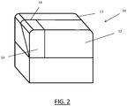
- FIG. 2 An embodiment of the present invention is schematically shown in FIG. 2 .
- This shows a perspective view of a closed printing machine 10, with an external housing 11 supported on a frame (15, see FIG. 3 ).
- a hood 12 provides access the interior of the printing machine 10.
- a separate door 13 is provided, which may be opened by lifting it about a hinge 14 connecting the door 13 to the housing 11.
- FIG. 3 shows both schematically and not to scale the printing machine 10 of FIG. 1 from the same viewpoint, though with the hood 12 and door 13 removed for clarity. In addition, and again for clarity, much of the printing machinery, in particular the print carriage, is omitted.
- the housing 11, and printing machinery and components are supported by frame 15.
- the internal volume of the printing machine 10 is partially separated into two distinct subvolumes by an internal partition 16: a main volume 17 and a container exchange volume 18, which is smaller than the main volume 17.
- the main volume 17 accommodates the printing machinery, including a print carriage with squeegee.
- Chases 22A, 22B are shown within the main volume 17, these chases 22A, 22B provide a receptacle for a printing screen S in use.
- chases are movable by actuators (not shown) to adjust the distance therebetween, so that a variety of differently-sized printing screens may be held by the chases 22A, 22B in use.
- a print carriage (not shown), including a squeegee, travels over the receptacle to act on a stencil S retained within, the direction of travel being parallel to the axes of the chases 22A, 22B, this direction conventionally being referred to as the "Y-direction".
- partition 16 includes an aperture 21, which permits communication between the two subvolumes. Passing through the aperture 21 proximate the upper edge thereof is a rail 19. Rail 19 extends at least partially across and over the receptacle, and in this embodiment across substantially the width of the printing machine 10, in a direction conventionally being referred to as the "X-direction". Rail 19 is statically fixed relative to the frame 15.
- the rail 19 is provided with a shuttle 23 mounted for travel along the rail 19.
- a cradle 24 is mounted on the shuttle 23 for travel therewith. Cradle 24 is adapted to retain a container for print medium (not shown). This container could for example comprise a cartridge or paste pot. It can be seen that shuttle 23 and cradle 24 are sized so as to fit through the aperture 21, so that they may travel into the main volume 17, and along the length of rail 19.
- FIG. 4 schematically shows, in a perspective view, a portion of the printing machine 10 of FIG. 2 with the shuttle 23 at the home position. More specifically, FIG. 4 shows the rail 19 with the shuttle 23 mounted thereon, with cradle 24 mounted on the shuttle 23.
- a paste cartridge 25 is located and securely retained within the cradle 24.
- the top of cradle 24 is open, so that a pneumatic line (not shown) can be fitted to a pneumatic connector 26 at the top of the paste cartridge 25. Supplying pressurised air through the pneumatic line and connector 26 will cause paste to be dispensed from the lower end of the paste cartridge 25.
- a printing medium sensor 27 is provided within the container exchange volume 18 so that it is proximate the lower end of a paste cartridge 25 when present in the cradle 24, and when the shuttle 23 is at the home position 20.
- the printing medium sensor 27 is operative to detect the presence of paste at the lower end of the paste cartridge 25 and output a simple YES / NO signal dependent on the determination of the presence of paste.
- the shuttle 23 comprises a wall section 28 at a lateral side of the cradle 24 furthest from the home position 20.
- the wall section 28 projects from the shuttle 23 towards the front of the printing machine 10, and is dimensioned so as to conform to the aperture 21, and furthermore located so as to align with the partition 16. In this way, when the shuttle 23 is at the home position 20, the cradle 24 is located in the container exchange volume 18 and the wall section 28 aligns with the partition 16 to isolate the container exchange volume 18 from the main volume 17.
- the rail 19 is provided with a programmable actuator 29 for moving the shuttle 23 along the rail 19.
- the rail 19 comprises a linear worm (not shown) selectively rotated by actuator 29, which drives the shuttle 23 along the rail as would be well understood by those skilled in the art.
- a pneumatic input 30 is provided to the rail 19, which connects to a pneumatic line (not shown) which runs along the rail 19 and connects to the shuttle 23. This pneumatic drive is used to effect vertical movement of the cradle 24 as will be described in more detail below, this vertical direction conventionally being referred to as the "Z-direction".
- the container exchange volume 18 is isolated from the main volume 17. It is possible for an operator to open the door 13 to access the container exchange volume 18, remove cartridge 25 from cradle 24 and exchange it with a fresh cartridge which can be placed in the cradle 24, all without having to open the hood 12. In this way the cartridge can be exchanged without interrupting the printing cycle, in complete safety for the operator.
- the need to exchange a cartridge is determined by the output from the printing medium sensor 27.
- FIG. 5 is a similar view to FIG. 4 , however in this case the shuttle 23 is shown moving to a dispensing position. Actuator 29 is caused to drive the linear worm to cause the shuttle 23 to move along the rail 19, through aperture 16, out of the container exchange volume 18 and into the main volume 17. It can be seen that the wall section 28 travels with the shuttle 23. It should be noted that with the cradle 24 in this configuration, the shuttle 23, cradle 24 and cartridge 25 can pass over the top of chase 22A (and indeed chase 22B if travel continues along the rail 19) to reach a position over the printing screen. However, to dispense printing medium properly, the cartridge 25 must be closer to the printing screen.
- the cradle 24 is adapted to be vertically movable with respect to the shuttle 23, so that it can be lowered into a dispensing position.
- the vertical position of the cradle 24 is controlled pneumatically, with the pneumatic input 30.
- FIG. 6 is a similar view to FIG. 5 , with the cradle 24 in its lowered dispensing position.
- the cradle 24 is mounted on shuttle 23 via a linear track 31, which guides the vertical motion.
- a dispensing action may commence, during which the shuttle 23, and hence also cradle 24 and cartridge 25, is moved along the rail 19 by driving actuator 29, while pneumatic pressure is applied to pneumatic connector 26, causing a bead or line of paste to be dispensed onto the printing screen S (see FIG. 3 ).
- the pneumatic pressure to pneumatic connector 26 is switched off, the cradle 24 is raised and the shuttle 23 is moved back to the home position 20 by actuator 29. Once the shuttle has reach the home position 20, printing of a workpiece through the printing screen S can be performed as is well-known in the art.
- Actuator 29 and the pneumatic drive are programmable so as to accommodate the chases 22A, 22B being set at different positions in the X-direction, and in particular to raise or lower the cradle 24 at preselected points of travel of the shuttle 23 along the rail 19.
- a control processor (not shown) is provided for controlling the actuator 29, the pneumatic supply for cradle 24 and the pneumatic supply for the cartridge 25 as required.
- FIG. 7 schematically shows a perspective view of a closed printing machine 40 in accordance with a second embodiment of the present invention.
- the external shape of the printing machine 40 is similar to that of the printing machine 10 shown in FIG. 2 , in particular housing 41 is very similar to housing 11.
- hood 42 and its connecting hinge 44 extend across the entirety of the front width of the printing machine 40.
- a lateral side of the hood 42 is provided with a hatch 43, which is mounted on hood 42 by a hinge 45, to open outwardly.
- FIG. 8 schematically shows, in perspective view, part of the internal configuration of the printing machine of FIG. 7 .
- FIG. 8 shows certain major components of the print medium dispensing system.
- a statically-fixed rail 49 is provided which extends across substantially the entire internal width of the printing machine 40.
- a shuttle 46 is mounted for travel along the rail 49, so as to traverse a printing screen (not shown) in use.
- the shuttle 46 carries a cradle 47 for retaining a print medium container (not shown), and a wall section 48 which projects perpendicularly to the rail 49.
- the cradle 47 is mounted on a projection 50 of the shuttle 46, which extends past the end of the rail 49 when the shuttle 46 is at an exchange position 51 proximate that end of the rail 49.
- the rail 49 and hatch 43 are aligned, so that when the shuttle 46 is moved along the rail 49 to the home position 51, the projection 50 abuts against and pushes open the hatch 43 from the inside of the printing machine 40, and passes to the outside of the printing machine 40.
- the cradle 47 therefore projects through the hatch 43, and outside the external housing 41.
- Wall section 48 then aligns with the external lateral surface of the external housing 41, providing at least partial isolation between the interior of the external housing 41 and the cradle 47.
- the wall section 48 is dimensioned to leave a gap between the wall section 48 and the hood 45, this gap being suitable for receiving the pneumatic line. As shown, the wall section 48 has a shorter dimension alone the Z-direction than the hatch 43, so that here a gap is formed above the wall section 48.
- the rails 19, 49 comprise linear worms driven by an actuator 29.
- Other drive systems are of course possible.
- the vertical movement of cradles 24, 47 described above uses a pneumatic system, other drive systems, for example electromechanical drive systems, may alternatively be used.
- the above-described embodiment shows the use of a paste cartridge, other containers, such as paste pots, and indeed other print media, such as conductive ink, may equally be dispensed.
- the hatch 43 could be opened in a variety of ways, for example by way of a dedicated actuator, or manually opened by an operator.
Landscapes
- Engineering & Computer Science (AREA)
- Mechanical Engineering (AREA)
- Manufacturing & Machinery (AREA)
- Microelectronics & Electronic Packaging (AREA)
- Electric Connection Of Electric Components To Printed Circuits (AREA)
- Screen Printers (AREA)
Description
- This invention relates to a printing machine for printing a print medium onto a workpiece.
- Industrial screen-printing machines typically apply print media, such as solder paste or conductive ink, onto a planar workpiece, such as a wafer or circuit board, by applying the print medium (e.g. solder paste) through a pattern of apertures in a screen (sometimes referred to as a foil or a stencil) using an angled blade or squeegee. The print medium is conventionally stored in a cartridge or pot, and is dispensed from the bottom of this by applying pressure to the top, using a pressurised air source. The cartridge is mounted on the print carriage, which also carries the squeegee. Since the print carriage travels along the length (i.e. front to back) of the printing machine, conventionally referred to as the Y direction, the cartridge can dispense to either the front or rear rail of the printing machine. The cartridge is also mounted for movement along the X direction, being normal to the Y axis and in the horizontal plane, relative to the print carriage. In operation therefore, the print carriage is moved to one end of the printing machine, and the cartridge is caused to dispense print medium while travelling along the X direction, so that print medium is dispensed to form an approximately linear bead of medium onto the printing screen. Because of the lack of space available within the printing machine, the cartridge may be rotatable between a horizontal orientation when it is not dispensing, and a vertical orientation for dispensing.
- The quantity of print medium present in the cartridge can be detected by a sensor, and an operator alerted when the cartridge requires replacement.
- There is a problem however that in order to effect replacement of a cartridge, it is necessary to open up the printing machine to obtain access to the cartridge.
FIG. 1 schematically shows a knownprinting machine 1 in a perspective view. Theprinting machine 1 is substantially cuboid, having anexternal housing 2 which covers theprinting machine 1 to prevent unauthorised access to the interior of theprinting machine 1. The housing is mounted on a frame (not visible inFIG. 1 ), which also supports internal machinery and components. Ahood 3 is provided to enable authorised access. This is connected to the remainder of thehousing 2 via ahinge 4, so that thehood 3 can be lifted up and rested on top of the housing. To further increase the safety of theprinting machine 1, an interlocking system (not shown) may be provided, which must be enabled prior to opening thehood 3. - For safety reasons it is necessary that the printing operation is shut down whenever the
hood 3 of theprinting machine 1 is opened, including when opened for the purpose of replacing a cartridge. This means that the print cycle is interrupted every time a cartridge is changed, which adds time to, and decreases efficiency of, the print process. - As specific prior art which shows such a problem may also be mentioned
US20120145014 A1 which shows the precharacterising features of the present invention, andUS20140366755 A1 which shows a printing machine with a print carriage supported by lateral side rails. - The present invention seeks to overcome this problem.
- In accordance with the present invention this aim is achieved by providing isolation for the print medium cartridge, such as an isolated chamber which can be opened and accessed without interrupting the print process. In order to enable such a configuration, the cartridge is also separated from the print carriage and carried on a static rail, fixed to the frame of the printing machine. While such an arrangement has the disadvantage that dispensing is only possible at on position, i.e. proximate the front or rear rail, it has been recognised that the advantages offered by this arrangement may outweigh the ability of conventional printing machines to dispense proximate both the front and rear rails of the printing machine.
- In accordance with a first aspect of the present invention there is provided a printing machine for printing a print medium onto a workpiece, comprising:
- a frame,
- an external housing supported by the frame,
- a print carriage,
- a receptacle for receiving a printing screen in use,
- a rail extending at least partially across and over the receptacle,
- a shuttle mounted for travel along the rail, and
- a cradle adapted to retain a container for print medium, the cradle being mounted on the shuttle,
- characterised in that the rail is statically fixed relative to the frame, and a portion of the rail comprises an exchange position for the shuttle, at which position a container for printing medium can be placed in or removed from the cradle, the container being separated from the print carriage.
- Other specific aspects and features of the present invention are set out in the accompanying claims.
- The invention will now be described with reference to the accompanying drawings (not to scale), in which:
-
FIG. 1 schematically shows a perspective view of a closed, known printing machine; -
FIG. 2 schematically shows a perspective view of a closed printing machine in accordance with an embodiment of the present invention; -
FIG. 3 schematically shows the printing machine ofFIG. 2 with the hood and door removed; -
FIG. 4 schematically shows a portion of the printing machine ofFIG. 2 with the shuttle at the home position; -
FIG. 5 is similar toFIG. 4 , with the shuttle moving to a dispensing position; -
FIG. 6 is similar toFIG. 5 , with the shuttle in a dispensing position; -
FIG. 7 schematically shows a perspective view of a closed printing machine in accordance with a second embodiment of the present invention; and -
FIG. 8 schematically shows part of the internal configuration of the printing machine ofFIG. 7 . - An embodiment of the present invention is schematically shown in
FIG. 2 . This shows a perspective view of a closedprinting machine 10, with anexternal housing 11 supported on a frame (15, seeFIG. 3 ). Ahood 12 provides access the interior of theprinting machine 10. In addition, aseparate door 13 is provided, which may be opened by lifting it about ahinge 14 connecting thedoor 13 to thehousing 11. -
FIG. 3 shows both schematically and not to scale theprinting machine 10 ofFIG. 1 from the same viewpoint, though with thehood 12 anddoor 13 removed for clarity. In addition, and again for clarity, much of the printing machinery, in particular the print carriage, is omitted. Thehousing 11, and printing machinery and components are supported byframe 15. The internal volume of theprinting machine 10 is partially separated into two distinct subvolumes by an internal partition 16: amain volume 17 and acontainer exchange volume 18, which is smaller than themain volume 17. Themain volume 17 accommodates the printing machinery, including a print carriage with squeegee.Chases main volume 17, thesechases chases chases - The separation between the
main volume 17 and thecontainer exchange volume 18 is only partial sincepartition 16 includes anaperture 21, which permits communication between the two subvolumes. Passing through theaperture 21 proximate the upper edge thereof is arail 19.Rail 19 extends at least partially across and over the receptacle, and in this embodiment across substantially the width of theprinting machine 10, in a direction conventionally being referred to as the "X-direction".Rail 19 is statically fixed relative to theframe 15. - As will be described in detail below, the
rail 19 is provided with ashuttle 23 mounted for travel along therail 19. A portion of therail 19, proximate an end thereof and located in thecontainer exchange volume 18, acts both as a "home"position 20 forshuttle 23, in which theshuttle 23 may rest between dispensing actions, and an "exchange" position, in which the print medium container (25, seeFIG. 4 ) may be exchanged, as will be described in more detail below. Acradle 24 is mounted on theshuttle 23 for travel therewith.Cradle 24 is adapted to retain a container for print medium (not shown). This container could for example comprise a cartridge or paste pot. It can be seen thatshuttle 23 andcradle 24 are sized so as to fit through theaperture 21, so that they may travel into themain volume 17, and along the length ofrail 19. -
FIG. 4 schematically shows, in a perspective view, a portion of theprinting machine 10 ofFIG. 2 with theshuttle 23 at the home position. More specifically,FIG. 4 shows therail 19 with theshuttle 23 mounted thereon, withcradle 24 mounted on theshuttle 23. Apaste cartridge 25 is located and securely retained within thecradle 24. The top ofcradle 24 is open, so that a pneumatic line (not shown) can be fitted to apneumatic connector 26 at the top of thepaste cartridge 25. Supplying pressurised air through the pneumatic line andconnector 26 will cause paste to be dispensed from the lower end of thepaste cartridge 25. Aprinting medium sensor 27 is provided within thecontainer exchange volume 18 so that it is proximate the lower end of apaste cartridge 25 when present in thecradle 24, and when theshuttle 23 is at thehome position 20. Theprinting medium sensor 27 is operative to detect the presence of paste at the lower end of thepaste cartridge 25 and output a simple YES / NO signal dependent on the determination of the presence of paste. - The
shuttle 23 comprises awall section 28 at a lateral side of thecradle 24 furthest from thehome position 20. Thewall section 28 projects from theshuttle 23 towards the front of theprinting machine 10, and is dimensioned so as to conform to theaperture 21, and furthermore located so as to align with thepartition 16. In this way, when theshuttle 23 is at thehome position 20, thecradle 24 is located in thecontainer exchange volume 18 and thewall section 28 aligns with thepartition 16 to isolate thecontainer exchange volume 18 from themain volume 17. - The
rail 19 is provided with aprogrammable actuator 29 for moving theshuttle 23 along therail 19. In this embodiment therail 19 comprises a linear worm (not shown) selectively rotated byactuator 29, which drives theshuttle 23 along the rail as would be well understood by those skilled in the art. Apneumatic input 30 is provided to therail 19, which connects to a pneumatic line (not shown) which runs along therail 19 and connects to theshuttle 23. This pneumatic drive is used to effect vertical movement of thecradle 24 as will be described in more detail below, this vertical direction conventionally being referred to as the "Z-direction". - When the
shuttle 23 is at thehome position 20 as shown, so that it is in thecontainer exchange volume 18, thecontainer exchange volume 18 is isolated from themain volume 17. It is possible for an operator to open thedoor 13 to access thecontainer exchange volume 18, removecartridge 25 fromcradle 24 and exchange it with a fresh cartridge which can be placed in thecradle 24, all without having to open thehood 12. In this way the cartridge can be exchanged without interrupting the printing cycle, in complete safety for the operator. The need to exchange a cartridge is determined by the output from theprinting medium sensor 27. -
FIG. 5 is a similar view toFIG. 4 , however in this case theshuttle 23 is shown moving to a dispensing position.Actuator 29 is caused to drive the linear worm to cause theshuttle 23 to move along therail 19, throughaperture 16, out of thecontainer exchange volume 18 and into themain volume 17. It can be seen that thewall section 28 travels with theshuttle 23. It should be noted that with thecradle 24 in this configuration, theshuttle 23,cradle 24 andcartridge 25 can pass over the top ofchase 22A (and indeed chase 22B if travel continues along the rail 19) to reach a position over the printing screen. However, to dispense printing medium properly, thecartridge 25 must be closer to the printing screen. To achieve this, thecradle 24 is adapted to be vertically movable with respect to theshuttle 23, so that it can be lowered into a dispensing position. The vertical position of thecradle 24 is controlled pneumatically, with thepneumatic input 30. -
FIG. 6 is a similar view toFIG. 5 , with thecradle 24 in its lowered dispensing position. Thecradle 24 is mounted onshuttle 23 via alinear track 31, which guides the vertical motion. For the avoidance of doubt, when thecradle 24 is at this lowered position to achieve satisfactory dispensing, it is unable to travel past eitherchase shuttle 23, and hence also cradle 24 andcartridge 25, is moved along therail 19 by drivingactuator 29, while pneumatic pressure is applied topneumatic connector 26, causing a bead or line of paste to be dispensed onto the printing screen S (seeFIG. 3 ). Following completion of dispensing, the pneumatic pressure topneumatic connector 26 is switched off, thecradle 24 is raised and theshuttle 23 is moved back to thehome position 20 byactuator 29. Once the shuttle has reach thehome position 20, printing of a workpiece through the printing screen S can be performed as is well-known in the art. -
Actuator 29 and the pneumatic drive are programmable so as to accommodate thechases cradle 24 at preselected points of travel of theshuttle 23 along therail 19. A control processor (not shown) is provided for controlling theactuator 29, the pneumatic supply forcradle 24 and the pneumatic supply for thecartridge 25 as required. -
FIG. 7 schematically shows a perspective view of aclosed printing machine 40 in accordance with a second embodiment of the present invention. The external shape of theprinting machine 40 is similar to that of theprinting machine 10 shown inFIG. 2 , inparticular housing 41 is very similar tohousing 11. In this embodiment however,hood 42 and its connectinghinge 44 extend across the entirety of the front width of theprinting machine 40. A lateral side of thehood 42 is provided with ahatch 43, which is mounted onhood 42 by ahinge 45, to open outwardly. -
FIG. 8 schematically shows, in perspective view, part of the internal configuration of the printing machine ofFIG. 7 . In particular,FIG. 8 shows certain major components of the print medium dispensing system. A statically-fixedrail 49 is provided which extends across substantially the entire internal width of theprinting machine 40. Ashuttle 46 is mounted for travel along therail 49, so as to traverse a printing screen (not shown) in use. As with the first embodiment, theshuttle 46 carries acradle 47 for retaining a print medium container (not shown), and awall section 48 which projects perpendicularly to therail 49. However, in this second embodiment, thecradle 47 is mounted on aprojection 50 of theshuttle 46, which extends past the end of therail 49 when theshuttle 46 is at anexchange position 51 proximate that end of therail 49. Therail 49 and hatch 43 are aligned, so that when theshuttle 46 is moved along therail 49 to thehome position 51, theprojection 50 abuts against and pushes open thehatch 43 from the inside of theprinting machine 40, and passes to the outside of theprinting machine 40. Thecradle 47 therefore projects through thehatch 43, and outside theexternal housing 41.Wall section 48 then aligns with the external lateral surface of theexternal housing 41, providing at least partial isolation between the interior of theexternal housing 41 and thecradle 47. In this position, an operator may safely access the cradle to exchange the paste medium container, without interrupting the printing process. It will be apparent to those skilled in the art that a pneumatic line (not shown) will still be attached to the top of the print medium container withincradle 47, and which passes into the interior of theprinting machine 40. To accommodate this pneumatic line, thewall section 48 is dimensioned to leave a gap between thewall section 48 and thehood 45, this gap being suitable for receiving the pneumatic line. As shown, thewall section 48 has a shorter dimension alone the Z-direction than thehatch 43, so that here a gap is formed above thewall section 48. - It can be seen that with this second embodiment, no internal partition is required. Those skilled in the art will also appreciate that in order to avoid unnecessary opening of the
hatch 43, between dispensing actions theshuttle 46 should in general return to ahome position 52 located between theexchange position 51 and that part of therail 49 which overlies the printing screen in use. Movement of theshuttle 46 to the exchange position would only be performed when a paste sensor (not shown) determines that the print medium container is empty. - The above-described embodiments are exemplary only, and other possibilities and alternatives within the scope of the invention will be apparent to those skilled in the art. For example, in the embodiment described above, the
rails actuator 29. Other drive systems are of course possible. Similarly, while the vertical movement ofcradles - With respect to the second embodiment, shown in
FIGs. 7 and 8 , thehatch 43 could be opened in a variety of ways, for example by way of a dedicated actuator, or manually opened by an operator. - It is possible that other equipment could be mounted for travel on the statically-fixed rail either in tandem or independently to the shuttle, such as, for example, a camera or other inspection equipment.
-
- 1 - Printing machine
- 2 - Housing
- 3 - Hood
- 4 - Hinge
- 10, 40 - Printing machine
- 11, 41 - Housing
- 12, 42 - Hood
- 13 - Door
- 14, 44 - Hinge
- 15 - Frame
- 16 - Partition
- 17 - Main volume
- 18 - Container exchange volume
- 19, 49 - Rail
- 20, 52 - Home position
- 21 - Aperture
- 22A, 22B - Chases
- 23, 46 - Shuttle
- 24, 47 - Cradle
- 25 - Paste cartridge
- 26 - Pneumatic connector
- 27 - Printing medium sensor
- 28, 48 Wall section
- 29 - Actuator
- 30 - Pneumatic input
- 31 - Linear track
- 43 - Hatch
- 45 - Hatch hinge
- 50 - Projection
- 51 - Exchange position
- S - Screen
Claims (12)
- A screen printing machine (10, 40) for printing a print medium onto a workpiece, comprising:a frame (15),an external housing (11, 41) supported by the frame (15),a print carriage with squeegee,a receptacle for receiving a printing screen (S) in use,a rail (19, 49) extending at least partially across and over the receptacle,a shuttle (23, 46) mounted for travel along the rail (19, 49), anda cradle (24, 47) adapted to retain a container (25) for print medium, the cradle (24, 47) being mounted on the shuttle (23, 46),characterised in that the rail (19, 49) is statically fixed relative to the frame, and a portion of the rail (19, 49) comprises an exchange position (51) for the shuttle (23, 46), at which position a container (25) for printing medium can be placed in or removed from the cradle (24, 47), the container (25) being separated from the print carriage.
- The printing machine (10) of claim 1, comprising an internal partition (16) which partially separates the interior of the printing machine (10) into a main volume (17) which comprises the receptacle, and a container exchange volume (18) in which the exchange position (51) is located.
- The printing machine of claim 2, wherein the shuttle (23) comprises a wall section (28), the wall section (28) being provided at a lateral side of the cradle (24), such that when the shuttle (23) is at the exchange position (51), the cradle (24) is located in the container exchange volume (18) and the wall section (28) aligns with the partition (16) to isolate the container exchange volume (18) from the main volume (17).
- The printing machine (10) of either of claims 2 and 3, wherein the housing (11) comprises a door (13) located proximate the container exchange volume (18), to provide access to the cradle (24) when the shuttle (23) is at the exchange position (51).
- The printing machine (10, 40) of claim 1, wherein the external housing (11, 41) comprises a hatch (43).
- The printing machine (40) of claim 5, wherein when the shuttle (46) is at the exchange position (51), the cradle (47) projects through the hatch (43) and outside the external housing (41).
- The printing machine (40) of claim 6, wherein the shuttle (46) comprises a wall section (48), the wall section (48) being provided at a lateral side of the cradle (47), such that when the shuttle (46) is at the exchange position (51), the cradle (47) is located externally of the external housing (41) and the wall section (48) aligns with the external housing (41) to isolate the cradle (47) from the interior of the housing (41).
- The printing machine (10, 40) of any of claims 1 to 7, comprising an actuator (29) for moving the shuttle (23, 46) along the rail (19, 49).
- The printing machine (10, 40) of any of claims 1 to 8, wherein the cradle (24, 47) is movable in a vertical direction relative to the shuttle (23, 46).
- The printing machine (10, 40) of claim 9, comprising a drive to effect vertical movement of the cradle (24, 47).
- The printing machine (10, 40) of claim 10, wherein the drive comprises a pneumatic drive.
- The printing machine (10, 40) of either of claims 10 and 11, wherein the drive is programmable to raise or lower the cradle (24, 47) at preselected points of travel of the shuttle (23, 46) along the rail (19, 49).
Applications Claiming Priority (1)
| Application Number | Priority Date | Filing Date | Title |
|---|---|---|---|
| GBGB1718674.3A GB201718674D0 (en) | 2017-11-12 | 2017-11-12 | Isolated paste dispenser |
Publications (2)
| Publication Number | Publication Date |
|---|---|
| EP3482940A1 EP3482940A1 (en) | 2019-05-15 |
| EP3482940B1 true EP3482940B1 (en) | 2020-05-13 |
Family
ID=60788304
Family Applications (1)
| Application Number | Title | Priority Date | Filing Date |
|---|---|---|---|
| EP18020495.0A Active EP3482940B1 (en) | 2017-11-12 | 2018-10-11 | Screen printing machine with isolated paste dispenser |
Country Status (7)
| Country | Link |
|---|---|
| US (1) | US10882305B2 (en) |
| EP (1) | EP3482940B1 (en) |
| JP (1) | JP6840119B2 (en) |
| KR (1) | KR102239945B1 (en) |
| CN (1) | CN109878201B (en) |
| GB (1) | GB201718674D0 (en) |
| TW (1) | TWI742314B (en) |
Families Citing this family (2)
| Publication number | Priority date | Publication date | Assignee | Title |
|---|---|---|---|---|
| CN113710488B (en) * | 2019-04-26 | 2023-07-14 | 株式会社富士 | Supply unit, printing device, and control method of printing device |
| GB2597702B (en) * | 2020-07-30 | 2024-06-05 | Asmpt Smt Singapore Pte Ltd | Isolated print medium dispenser |
Family Cites Families (18)
| Publication number | Priority date | Publication date | Assignee | Title |
|---|---|---|---|---|
| JP2504643B2 (en) * | 1991-08-23 | 1996-06-05 | 株式会社日立製作所 | Conductive paste filling device |
| JP3314425B2 (en) * | 1992-12-02 | 2002-08-12 | 松下電器産業株式会社 | Screen printing machine and printing method thereof |
| US6101937A (en) * | 1997-02-12 | 2000-08-15 | Minami Co., Ltd. | Screen printing machine having paste dispensers and a squeegee unit |
| US6328415B1 (en) * | 1999-04-30 | 2001-12-11 | Hewlett-Packard Company | Displaceable print cartridge chute |
| JP3838240B2 (en) | 2002-04-01 | 2006-10-25 | セイコーエプソン株式会社 | Liquid ejecting apparatus, control method and control program for liquid ejecting apparatus |
| JP4675658B2 (en) | 2005-03-28 | 2011-04-27 | パナソニック株式会社 | Screen printing device |
| JP5252897B2 (en) | 2007-11-30 | 2013-07-31 | ヤマハ発動機株式会社 | Screen printing machine |
| JP4643719B2 (en) * | 2009-02-09 | 2011-03-02 | ヤマハ発動機株式会社 | Solder supply apparatus, printing apparatus and printing method |
| JP5062198B2 (en) | 2009-02-24 | 2012-10-31 | パナソニック株式会社 | Screen printing machine and screen printing method |
| FR2943634B1 (en) | 2009-03-24 | 2011-04-22 | Cer | MACHINE AND METHOD FOR MARKING OR LABELING |
| JP5537851B2 (en) * | 2009-07-10 | 2014-07-02 | 富士機械製造株式会社 | Screen printing machine |
| US8739699B2 (en) * | 2010-12-08 | 2014-06-03 | Illinois Tool Works Inc. | Combination stencil printer and dispenser and related methods |
| JP2014151507A (en) | 2013-02-07 | 2014-08-25 | Panasonic Corp | Paste feeder, screen printer, paste feeding method, and screen printing metho |
| JP5895133B2 (en) * | 2013-06-12 | 2016-03-30 | パナソニックIpマネジメント株式会社 | Paste supply device, screen printing machine, paste supply method and screen printing method |
| JP2016179579A (en) | 2015-03-24 | 2016-10-13 | パナソニックIpマネジメント株式会社 | Screen printing apparatus, paste pot and screen printing method |
| WO2017048905A1 (en) | 2015-09-15 | 2017-03-23 | Milara Incorporated | System and method for depositing a material on a workpiece |
| JP6971033B2 (en) | 2017-01-24 | 2021-11-24 | 株式会社Fuji | Screen printing machine |
| KR102799657B1 (en) | 2017-02-08 | 2025-04-23 | 삼성전자주식회사 | Screen printer for printed circuit board |
-
2017
- 2017-11-12 GB GBGB1718674.3A patent/GB201718674D0/en not_active Ceased
-
2018
- 2018-10-11 EP EP18020495.0A patent/EP3482940B1/en active Active
- 2018-10-19 TW TW107136845A patent/TWI742314B/en active
- 2018-11-02 CN CN201811303415.0A patent/CN109878201B/en active Active
- 2018-11-05 US US16/180,656 patent/US10882305B2/en active Active
- 2018-11-09 KR KR1020180137033A patent/KR102239945B1/en active Active
- 2018-11-09 JP JP2018211355A patent/JP6840119B2/en active Active
Non-Patent Citations (1)
| Title |
|---|
| None * |
Also Published As
| Publication number | Publication date |
|---|---|
| US10882305B2 (en) | 2021-01-05 |
| KR20190054946A (en) | 2019-05-22 |
| TW201918382A (en) | 2019-05-16 |
| TWI742314B (en) | 2021-10-11 |
| EP3482940A1 (en) | 2019-05-15 |
| US20190143668A1 (en) | 2019-05-16 |
| KR102239945B1 (en) | 2021-04-14 |
| CN109878201B (en) | 2021-04-06 |
| CN109878201A (en) | 2019-06-14 |
| GB201718674D0 (en) | 2017-12-27 |
| JP2019089327A (en) | 2019-06-13 |
| JP6840119B2 (en) | 2021-03-10 |
Similar Documents
| Publication | Publication Date | Title |
|---|---|---|
| US10882305B2 (en) | Isolated paste dispenser | |
| US8186825B2 (en) | Printing apparatus | |
| CN115157862B (en) | Liquid ejection device, and detection method of liquid ejection device | |
| EP3192658A2 (en) | Waste liquid container and attachment | |
| CN113453904B (en) | Shipping bracket for rolls of a printing unit in a printing machine | |
| JP2018118407A (en) | Screen printing machine | |
| CN104228322A (en) | Paste supply apparatus, screen printing machine, paste supply method and screen printing method | |
| US10495988B2 (en) | Printing device and printing method | |
| JP2015522447A (en) | Additional printing equipment in sheet-fed printing machines. | |
| JP2026009226A (en) | Replacement frame | |
| US11490525B2 (en) | Supply unit, printing device, and method for controlling printing device | |
| JP2023533102A5 (en) | ||
| US11833843B2 (en) | Isolated print medium dispenser | |
| US9994033B2 (en) | Liquid supply device and liquid ejecting apparatus | |
| JP2008254294A (en) | Resin sealing device and suction hole clogging detection method | |
| JP2015101073A (en) | Printer and control method of the same | |
| US12377583B2 (en) | Automatic gel ribbon thickness adjustment device | |
| JP2020082610A (en) | Ink jet printer | |
| KR20130104711A (en) | Doctoring apparatus of gravure printing machine | |
| WO2022113899A1 (en) | Printing device | |
| CN109249699B (en) | Liquid ejection device and detection method of interference object | |
| JP2024084186A (en) | Protective Covers and Work Equipment |
Legal Events
| Date | Code | Title | Description |
|---|---|---|---|
| PUAI | Public reference made under article 153(3) epc to a published international application that has entered the european phase |
Free format text: ORIGINAL CODE: 0009012 |
|
| STAA | Information on the status of an ep patent application or granted ep patent |
Free format text: STATUS: THE APPLICATION HAS BEEN PUBLISHED |
|
| AK | Designated contracting states |
Kind code of ref document: A1 Designated state(s): AL AT BE BG CH CY CZ DE DK EE ES FI FR GB GR HR HU IE IS IT LI LT LU LV MC MK MT NL NO PL PT RO RS SE SI SK SM TR |
|
| AX | Request for extension of the european patent |
Extension state: BA ME |
|
| STAA | Information on the status of an ep patent application or granted ep patent |
Free format text: STATUS: REQUEST FOR EXAMINATION WAS MADE |
|
| 17P | Request for examination filed |
Effective date: 20191112 |
|
| RBV | Designated contracting states (corrected) |
Designated state(s): AL AT BE BG CH CY CZ DE DK EE ES FI FR GB GR HR HU IE IS IT LI LT LU LV MC MK MT NL NO PL PT RO RS SE SI SK SM TR |
|
| RIC1 | Information provided on ipc code assigned before grant |
Ipc: B41F 15/40 20060101ALI20191220BHEP Ipc: B41F 15/42 20060101ALI20191220BHEP Ipc: B41F 15/08 20060101AFI20191220BHEP Ipc: H05K 3/12 20060101ALI20191220BHEP |
|
| GRAP | Despatch of communication of intention to grant a patent |
Free format text: ORIGINAL CODE: EPIDOSNIGR1 |
|
| STAA | Information on the status of an ep patent application or granted ep patent |
Free format text: STATUS: GRANT OF PATENT IS INTENDED |
|
| INTG | Intention to grant announced |
Effective date: 20200206 |
|
| GRAS | Grant fee paid |
Free format text: ORIGINAL CODE: EPIDOSNIGR3 |
|
| GRAA | (expected) grant |
Free format text: ORIGINAL CODE: 0009210 |
|
| STAA | Information on the status of an ep patent application or granted ep patent |
Free format text: STATUS: THE PATENT HAS BEEN GRANTED |
|
| AK | Designated contracting states |
Kind code of ref document: B1 Designated state(s): AL AT BE BG CH CY CZ DE DK EE ES FI FR GB GR HR HU IE IS IT LI LT LU LV MC MK MT NL NO PL PT RO RS SE SI SK SM TR |
|
| REG | Reference to a national code |
Ref country code: GB Ref legal event code: FG4D |
|
| REG | Reference to a national code |
Ref country code: CH Ref legal event code: EP |
|
| REG | Reference to a national code |
Ref country code: DE Ref legal event code: R096 Ref document number: 602018004239 Country of ref document: DE |
|
| REG | Reference to a national code |
Ref country code: AT Ref legal event code: REF Ref document number: 1269727 Country of ref document: AT Kind code of ref document: T Effective date: 20200615 |
|
| REG | Reference to a national code |
Ref country code: LT Ref legal event code: MG4D |
|
| REG | Reference to a national code |
Ref country code: NL Ref legal event code: MP Effective date: 20200513 |
|
| PG25 | Lapsed in a contracting state [announced via postgrant information from national office to epo] |
Ref country code: IS Free format text: LAPSE BECAUSE OF FAILURE TO SUBMIT A TRANSLATION OF THE DESCRIPTION OR TO PAY THE FEE WITHIN THE PRESCRIBED TIME-LIMIT Effective date: 20200913 Ref country code: PT Free format text: LAPSE BECAUSE OF FAILURE TO SUBMIT A TRANSLATION OF THE DESCRIPTION OR TO PAY THE FEE WITHIN THE PRESCRIBED TIME-LIMIT Effective date: 20200914 Ref country code: LT Free format text: LAPSE BECAUSE OF FAILURE TO SUBMIT A TRANSLATION OF THE DESCRIPTION OR TO PAY THE FEE WITHIN THE PRESCRIBED TIME-LIMIT Effective date: 20200513 Ref country code: NO Free format text: LAPSE BECAUSE OF FAILURE TO SUBMIT A TRANSLATION OF THE DESCRIPTION OR TO PAY THE FEE WITHIN THE PRESCRIBED TIME-LIMIT Effective date: 20200813 Ref country code: FI Free format text: LAPSE BECAUSE OF FAILURE TO SUBMIT A TRANSLATION OF THE DESCRIPTION OR TO PAY THE FEE WITHIN THE PRESCRIBED TIME-LIMIT Effective date: 20200513 Ref country code: GR Free format text: LAPSE BECAUSE OF FAILURE TO SUBMIT A TRANSLATION OF THE DESCRIPTION OR TO PAY THE FEE WITHIN THE PRESCRIBED TIME-LIMIT Effective date: 20200814 Ref country code: SE Free format text: LAPSE BECAUSE OF FAILURE TO SUBMIT A TRANSLATION OF THE DESCRIPTION OR TO PAY THE FEE WITHIN THE PRESCRIBED TIME-LIMIT Effective date: 20200513 |
|
| PG25 | Lapsed in a contracting state [announced via postgrant information from national office to epo] |
Ref country code: BG Free format text: LAPSE BECAUSE OF FAILURE TO SUBMIT A TRANSLATION OF THE DESCRIPTION OR TO PAY THE FEE WITHIN THE PRESCRIBED TIME-LIMIT Effective date: 20200813 Ref country code: LV Free format text: LAPSE BECAUSE OF FAILURE TO SUBMIT A TRANSLATION OF THE DESCRIPTION OR TO PAY THE FEE WITHIN THE PRESCRIBED TIME-LIMIT Effective date: 20200513 Ref country code: RS Free format text: LAPSE BECAUSE OF FAILURE TO SUBMIT A TRANSLATION OF THE DESCRIPTION OR TO PAY THE FEE WITHIN THE PRESCRIBED TIME-LIMIT Effective date: 20200513 Ref country code: HR Free format text: LAPSE BECAUSE OF FAILURE TO SUBMIT A TRANSLATION OF THE DESCRIPTION OR TO PAY THE FEE WITHIN THE PRESCRIBED TIME-LIMIT Effective date: 20200513 |
|
| REG | Reference to a national code |
Ref country code: AT Ref legal event code: MK05 Ref document number: 1269727 Country of ref document: AT Kind code of ref document: T Effective date: 20200513 |
|
| PG25 | Lapsed in a contracting state [announced via postgrant information from national office to epo] |
Ref country code: AL Free format text: LAPSE BECAUSE OF FAILURE TO SUBMIT A TRANSLATION OF THE DESCRIPTION OR TO PAY THE FEE WITHIN THE PRESCRIBED TIME-LIMIT Effective date: 20200513 Ref country code: NL Free format text: LAPSE BECAUSE OF FAILURE TO SUBMIT A TRANSLATION OF THE DESCRIPTION OR TO PAY THE FEE WITHIN THE PRESCRIBED TIME-LIMIT Effective date: 20200513 |
|
| PG25 | Lapsed in a contracting state [announced via postgrant information from national office to epo] |
Ref country code: CZ Free format text: LAPSE BECAUSE OF FAILURE TO SUBMIT A TRANSLATION OF THE DESCRIPTION OR TO PAY THE FEE WITHIN THE PRESCRIBED TIME-LIMIT Effective date: 20200513 Ref country code: RO Free format text: LAPSE BECAUSE OF FAILURE TO SUBMIT A TRANSLATION OF THE DESCRIPTION OR TO PAY THE FEE WITHIN THE PRESCRIBED TIME-LIMIT Effective date: 20200513 Ref country code: DK Free format text: LAPSE BECAUSE OF FAILURE TO SUBMIT A TRANSLATION OF THE DESCRIPTION OR TO PAY THE FEE WITHIN THE PRESCRIBED TIME-LIMIT Effective date: 20200513 Ref country code: EE Free format text: LAPSE BECAUSE OF FAILURE TO SUBMIT A TRANSLATION OF THE DESCRIPTION OR TO PAY THE FEE WITHIN THE PRESCRIBED TIME-LIMIT Effective date: 20200513 Ref country code: SM Free format text: LAPSE BECAUSE OF FAILURE TO SUBMIT A TRANSLATION OF THE DESCRIPTION OR TO PAY THE FEE WITHIN THE PRESCRIBED TIME-LIMIT Effective date: 20200513 Ref country code: AT Free format text: LAPSE BECAUSE OF FAILURE TO SUBMIT A TRANSLATION OF THE DESCRIPTION OR TO PAY THE FEE WITHIN THE PRESCRIBED TIME-LIMIT Effective date: 20200513 Ref country code: ES Free format text: LAPSE BECAUSE OF FAILURE TO SUBMIT A TRANSLATION OF THE DESCRIPTION OR TO PAY THE FEE WITHIN THE PRESCRIBED TIME-LIMIT Effective date: 20200513 |
|
| REG | Reference to a national code |
Ref country code: DE Ref legal event code: R097 Ref document number: 602018004239 Country of ref document: DE |
|
| PG25 | Lapsed in a contracting state [announced via postgrant information from national office to epo] |
Ref country code: SK Free format text: LAPSE BECAUSE OF FAILURE TO SUBMIT A TRANSLATION OF THE DESCRIPTION OR TO PAY THE FEE WITHIN THE PRESCRIBED TIME-LIMIT Effective date: 20200513 Ref country code: PL Free format text: LAPSE BECAUSE OF FAILURE TO SUBMIT A TRANSLATION OF THE DESCRIPTION OR TO PAY THE FEE WITHIN THE PRESCRIBED TIME-LIMIT Effective date: 20200513 |
|
| PLBE | No opposition filed within time limit |
Free format text: ORIGINAL CODE: 0009261 |
|
| STAA | Information on the status of an ep patent application or granted ep patent |
Free format text: STATUS: NO OPPOSITION FILED WITHIN TIME LIMIT |
|
| 26N | No opposition filed |
Effective date: 20210216 |
|
| PG25 | Lapsed in a contracting state [announced via postgrant information from national office to epo] |
Ref country code: SI Free format text: LAPSE BECAUSE OF FAILURE TO SUBMIT A TRANSLATION OF THE DESCRIPTION OR TO PAY THE FEE WITHIN THE PRESCRIBED TIME-LIMIT Effective date: 20200513 |
|
| PG25 | Lapsed in a contracting state [announced via postgrant information from national office to epo] |
Ref country code: LU Free format text: LAPSE BECAUSE OF NON-PAYMENT OF DUE FEES Effective date: 20201011 Ref country code: MC Free format text: LAPSE BECAUSE OF FAILURE TO SUBMIT A TRANSLATION OF THE DESCRIPTION OR TO PAY THE FEE WITHIN THE PRESCRIBED TIME-LIMIT Effective date: 20200513 |
|
| REG | Reference to a national code |
Ref country code: BE Ref legal event code: MM Effective date: 20201031 |
|
| PG25 | Lapsed in a contracting state [announced via postgrant information from national office to epo] |
Ref country code: BE Free format text: LAPSE BECAUSE OF NON-PAYMENT OF DUE FEES Effective date: 20201031 |
|
| PG25 | Lapsed in a contracting state [announced via postgrant information from national office to epo] |
Ref country code: IE Free format text: LAPSE BECAUSE OF NON-PAYMENT OF DUE FEES Effective date: 20201011 |
|
| REG | Reference to a national code |
Ref country code: CH Ref legal event code: PL |
|
| PG25 | Lapsed in a contracting state [announced via postgrant information from national office to epo] |
Ref country code: TR Free format text: LAPSE BECAUSE OF FAILURE TO SUBMIT A TRANSLATION OF THE DESCRIPTION OR TO PAY THE FEE WITHIN THE PRESCRIBED TIME-LIMIT Effective date: 20200513 Ref country code: MT Free format text: LAPSE BECAUSE OF FAILURE TO SUBMIT A TRANSLATION OF THE DESCRIPTION OR TO PAY THE FEE WITHIN THE PRESCRIBED TIME-LIMIT Effective date: 20200513 Ref country code: CY Free format text: LAPSE BECAUSE OF FAILURE TO SUBMIT A TRANSLATION OF THE DESCRIPTION OR TO PAY THE FEE WITHIN THE PRESCRIBED TIME-LIMIT Effective date: 20200513 |
|
| PG25 | Lapsed in a contracting state [announced via postgrant information from national office to epo] |
Ref country code: MK Free format text: LAPSE BECAUSE OF FAILURE TO SUBMIT A TRANSLATION OF THE DESCRIPTION OR TO PAY THE FEE WITHIN THE PRESCRIBED TIME-LIMIT Effective date: 20200513 |
|
| PG25 | Lapsed in a contracting state [announced via postgrant information from national office to epo] |
Ref country code: LI Free format text: LAPSE BECAUSE OF NON-PAYMENT OF DUE FEES Effective date: 20211031 Ref country code: CH Free format text: LAPSE BECAUSE OF NON-PAYMENT OF DUE FEES Effective date: 20211031 |
|
| REG | Reference to a national code |
Ref country code: DE Ref legal event code: R081 Ref document number: 602018004239 Country of ref document: DE Owner name: ASMPT SMT SINGAPORE PTE. LTD., SG Free format text: FORMER OWNER: ASM ASSEMBLY SYSTEMS SINGAPORE PTE LTD., SINGAPUR, SG |
|
| P01 | Opt-out of the competence of the unified patent court (upc) registered |
Effective date: 20230530 |
|
| PGFP | Annual fee paid to national office [announced via postgrant information from national office to epo] |
Ref country code: DE Payment date: 20251021 Year of fee payment: 8 |
|
| PGFP | Annual fee paid to national office [announced via postgrant information from national office to epo] |
Ref country code: GB Payment date: 20251022 Year of fee payment: 8 |
|
| PGFP | Annual fee paid to national office [announced via postgrant information from national office to epo] |
Ref country code: IT Payment date: 20251024 Year of fee payment: 8 |
|
| PGFP | Annual fee paid to national office [announced via postgrant information from national office to epo] |
Ref country code: FR Payment date: 20251030 Year of fee payment: 8 |