EP3482911A1 - Support system for a transport system and workpiece holder for same - Google Patents
Support system for a transport system and workpiece holder for same Download PDFInfo
- Publication number
- EP3482911A1 EP3482911A1 EP17201412.8A EP17201412A EP3482911A1 EP 3482911 A1 EP3482911 A1 EP 3482911A1 EP 17201412 A EP17201412 A EP 17201412A EP 3482911 A1 EP3482911 A1 EP 3482911A1
- Authority
- EP
- European Patent Office
- Prior art keywords
- workpiece
- carrier
- workpiece carrier
- hole
- manufacturing
- Prior art date
- Legal status (The legal status is an assumption and is not a legal conclusion. Google has not performed a legal analysis and makes no representation as to the accuracy of the status listed.)
- Withdrawn
Links
Images


Classifications
-
- B—PERFORMING OPERATIONS; TRANSPORTING
- B29—WORKING OF PLASTICS; WORKING OF SUBSTANCES IN A PLASTIC STATE IN GENERAL
- B29C—SHAPING OR JOINING OF PLASTICS; SHAPING OF MATERIAL IN A PLASTIC STATE, NOT OTHERWISE PROVIDED FOR; AFTER-TREATMENT OF THE SHAPED PRODUCTS, e.g. REPAIRING
- B29C64/00—Additive manufacturing, i.e. manufacturing of three-dimensional [3D] objects by additive deposition, additive agglomeration or additive layering, e.g. by 3D printing, stereolithography or selective laser sintering
- B29C64/20—Apparatus for additive manufacturing; Details thereof or accessories therefor
- B29C64/245—Platforms or substrates
-
- B—PERFORMING OPERATIONS; TRANSPORTING
- B22—CASTING; POWDER METALLURGY
- B22F—WORKING METALLIC POWDER; MANUFACTURE OF ARTICLES FROM METALLIC POWDER; MAKING METALLIC POWDER; APPARATUS OR DEVICES SPECIALLY ADAPTED FOR METALLIC POWDER
- B22F10/00—Additive manufacturing of workpieces or articles from metallic powder
- B22F10/40—Structures for supporting workpieces or articles during manufacture and removed afterwards
- B22F10/47—Structures for supporting workpieces or articles during manufacture and removed afterwards characterised by structural features
-
- B—PERFORMING OPERATIONS; TRANSPORTING
- B25—HAND TOOLS; PORTABLE POWER-DRIVEN TOOLS; MANIPULATORS
- B25B—TOOLS OR BENCH DEVICES NOT OTHERWISE PROVIDED FOR, FOR FASTENING, CONNECTING, DISENGAGING OR HOLDING
- B25B11/00—Work holders not covered by any preceding group in the subclass, e.g. magnetic work holders, vacuum work holders
-
- B—PERFORMING OPERATIONS; TRANSPORTING
- B29—WORKING OF PLASTICS; WORKING OF SUBSTANCES IN A PLASTIC STATE IN GENERAL
- B29C—SHAPING OR JOINING OF PLASTICS; SHAPING OF MATERIAL IN A PLASTIC STATE, NOT OTHERWISE PROVIDED FOR; AFTER-TREATMENT OF THE SHAPED PRODUCTS, e.g. REPAIRING
- B29C64/00—Additive manufacturing, i.e. manufacturing of three-dimensional [3D] objects by additive deposition, additive agglomeration or additive layering, e.g. by 3D printing, stereolithography or selective laser sintering
- B29C64/10—Processes of additive manufacturing
- B29C64/141—Processes of additive manufacturing using only solid materials
- B29C64/153—Processes of additive manufacturing using only solid materials using layers of powder being selectively joined, e.g. by selective laser sintering or melting
-
- B—PERFORMING OPERATIONS; TRANSPORTING
- B33—ADDITIVE MANUFACTURING TECHNOLOGY
- B33Y—ADDITIVE MANUFACTURING, i.e. MANUFACTURING OF THREE-DIMENSIONAL [3-D] OBJECTS BY ADDITIVE DEPOSITION, ADDITIVE AGGLOMERATION OR ADDITIVE LAYERING, e.g. BY 3-D PRINTING, STEREOLITHOGRAPHY OR SELECTIVE LASER SINTERING
- B33Y10/00—Processes of additive manufacturing
-
- B—PERFORMING OPERATIONS; TRANSPORTING
- B22—CASTING; POWDER METALLURGY
- B22F—WORKING METALLIC POWDER; MANUFACTURE OF ARTICLES FROM METALLIC POWDER; MAKING METALLIC POWDER; APPARATUS OR DEVICES SPECIALLY ADAPTED FOR METALLIC POWDER
- B22F10/00—Additive manufacturing of workpieces or articles from metallic powder
- B22F10/20—Direct sintering or melting
- B22F10/28—Powder bed fusion, e.g. selective laser melting [SLM] or electron beam melting [EBM]
-
- B—PERFORMING OPERATIONS; TRANSPORTING
- B22—CASTING; POWDER METALLURGY
- B22F—WORKING METALLIC POWDER; MANUFACTURE OF ARTICLES FROM METALLIC POWDER; MAKING METALLIC POWDER; APPARATUS OR DEVICES SPECIALLY ADAPTED FOR METALLIC POWDER
- B22F12/00—Apparatus or devices specially adapted for additive manufacturing; Auxiliary means for additive manufacturing; Combinations of additive manufacturing apparatus or devices with other processing apparatus or devices
- B22F12/22—Driving means
- B22F12/226—Driving means for rotary motion
-
- B—PERFORMING OPERATIONS; TRANSPORTING
- B22—CASTING; POWDER METALLURGY
- B22F—WORKING METALLIC POWDER; MANUFACTURE OF ARTICLES FROM METALLIC POWDER; MAKING METALLIC POWDER; APPARATUS OR DEVICES SPECIALLY ADAPTED FOR METALLIC POWDER
- B22F12/00—Apparatus or devices specially adapted for additive manufacturing; Auxiliary means for additive manufacturing; Combinations of additive manufacturing apparatus or devices with other processing apparatus or devices
- B22F12/30—Platforms or substrates
-
- B—PERFORMING OPERATIONS; TRANSPORTING
- B22—CASTING; POWDER METALLURGY
- B22F—WORKING METALLIC POWDER; MANUFACTURE OF ARTICLES FROM METALLIC POWDER; MAKING METALLIC POWDER; APPARATUS OR DEVICES SPECIALLY ADAPTED FOR METALLIC POWDER
- B22F2999/00—Aspects linked to processes or compositions used in powder metallurgy
-
- B—PERFORMING OPERATIONS; TRANSPORTING
- B29—WORKING OF PLASTICS; WORKING OF SUBSTANCES IN A PLASTIC STATE IN GENERAL
- B29C—SHAPING OR JOINING OF PLASTICS; SHAPING OF MATERIAL IN A PLASTIC STATE, NOT OTHERWISE PROVIDED FOR; AFTER-TREATMENT OF THE SHAPED PRODUCTS, e.g. REPAIRING
- B29C64/00—Additive manufacturing, i.e. manufacturing of three-dimensional [3D] objects by additive deposition, additive agglomeration or additive layering, e.g. by 3D printing, stereolithography or selective laser sintering
- B29C64/10—Processes of additive manufacturing
- B29C64/188—Processes of additive manufacturing involving additional operations performed on the added layers, e.g. smoothing, grinding or thickness control
-
- B—PERFORMING OPERATIONS; TRANSPORTING
- B29—WORKING OF PLASTICS; WORKING OF SUBSTANCES IN A PLASTIC STATE IN GENERAL
- B29C—SHAPING OR JOINING OF PLASTICS; SHAPING OF MATERIAL IN A PLASTIC STATE, NOT OTHERWISE PROVIDED FOR; AFTER-TREATMENT OF THE SHAPED PRODUCTS, e.g. REPAIRING
- B29C64/00—Additive manufacturing, i.e. manufacturing of three-dimensional [3D] objects by additive deposition, additive agglomeration or additive layering, e.g. by 3D printing, stereolithography or selective laser sintering
- B29C64/30—Auxiliary operations or equipment
- B29C64/307—Handling of material to be used in additive manufacturing
-
- B—PERFORMING OPERATIONS; TRANSPORTING
- B33—ADDITIVE MANUFACTURING TECHNOLOGY
- B33Y—ADDITIVE MANUFACTURING, i.e. MANUFACTURING OF THREE-DIMENSIONAL [3-D] OBJECTS BY ADDITIVE DEPOSITION, ADDITIVE AGGLOMERATION OR ADDITIVE LAYERING, e.g. BY 3-D PRINTING, STEREOLITHOGRAPHY OR SELECTIVE LASER SINTERING
- B33Y30/00—Apparatus for additive manufacturing; Details thereof or accessories therefor
-
- Y—GENERAL TAGGING OF NEW TECHNOLOGICAL DEVELOPMENTS; GENERAL TAGGING OF CROSS-SECTIONAL TECHNOLOGIES SPANNING OVER SEVERAL SECTIONS OF THE IPC; TECHNICAL SUBJECTS COVERED BY FORMER USPC CROSS-REFERENCE ART COLLECTIONS [XRACs] AND DIGESTS
- Y02—TECHNOLOGIES OR APPLICATIONS FOR MITIGATION OR ADAPTATION AGAINST CLIMATE CHANGE
- Y02P—CLIMATE CHANGE MITIGATION TECHNOLOGIES IN THE PRODUCTION OR PROCESSING OF GOODS
- Y02P10/00—Technologies related to metal processing
- Y02P10/25—Process efficiency
Abstract
Es wird ein Trägersystem für eine Fertigungsanlage und ein Werkstückträger (8) zur Verwendung im Trägersystem beschrieben. Das Trägersystem umfasst einen Grundträger (6), welcher dazu eingerichtet ist, in einer Prozesskammer der Fertigungsanlage befestigt zu werden, und welcher mindestens ein Positionierungselement umfasst, und einen Werkstückträger (8), auf dem nach einem Herstellungsverfahren umfassend schichtweises Auftragen eines pulverförmigen Rohmaterials ein Werkstück herstellbar ist. Der Werkstückträger (8) weist eine Unterseite (12) und eine der Unterseite im Wesentlichen gegenüberliegende Bauseite als Oberseite (11) auf. Der Werkstückträger (8) weist an seiner Unterseite (12) mindestens eine erste Positionierungseinrichtung zur positionsgenauen, lösbaren Anbringung an dem Grundträger (6) der Herstellungsvorrichtung auf. Das mindestens eine Positionierungselement (10) und die mindestens eine erste Positionierungseinrichtung (14) sind komplementär ausgebildet und bilden ein Zapfen-Loch-Paar. Mindestens ein Abschnitt (87) des Zapfens ist aus einem ersten Material mit einem ersten Wärmeausdehnungskoeffizient gebildet und das Loch ist in einem für die Positionsgenauigkeit maßgebenden Abschnitt aus einem zweiten Material mit einem zweiten Wärmeausdehnungskoeffizient gebildet. In einer ersten Alternative ist der zweite Wärmeausdehnungskoeffizient geringer als der erste Wärmeausdehnungskoeffizient, sodass bei einer Erhöhung einer Temperatur des Trägersystems während des Herstellungsverfahrens durch Ausdehnung des Abschnitts (87) des Zapfens eine Klemmwirkung zwischen Zapfen und dem umgebenden Loch auftritt. In einer zweiten Alternative ist der erste Wärmeausdehnungskoeffizient geringer ist als der zweite Wärmeausdehnungskoeffizient, sodass bei einer Erhöhung einer Temperatur des Trägersystems während des Herstellungsverfahrens durch Ausdehnung des Halterungsabschnitts (28, 42, 91) des Lochs eine Klemmwirkung zwischen Zapfen und dem umgebenden Loch auftritt. Ferner werden Verfahren zum Herstellen eines Werkstücks beschrieben.A support system for a manufacturing plant and a workpiece carrier (8) for use in the carrier system is described. The support system comprises a base support (6) which is adapted to be fixed in a process chamber of the production facility, and which comprises at least one positioning element, and a workpiece carrier (8) on which a workpiece according to a manufacturing method comprising layer-wise application of a powdery raw material can be produced. The workpiece carrier (8) has a lower side (12) and a side of the building substantially opposite to the lower side as the upper side (11). The workpiece carrier (8) has on its underside (12) at least one first positioning device for positionally accurate, releasable attachment to the base support (6) of the manufacturing device. The at least one positioning element (10) and the at least one first positioning device (14) are designed to be complementary and form a pin-hole pair. At least a portion (87) of the pin is formed of a first material having a first coefficient of thermal expansion, and the hole is formed in a position accuracy determining portion of a second material having a second thermal expansion coefficient. In a first alternative, the second coefficient of thermal expansion is less than the first coefficient of thermal expansion, such that when the temperature of the carrier system is increased during the manufacturing process by expansion of the portion (87) of the pin, a clamping action between the pin and the surrounding hole occurs. In a second alternative, the first coefficient of thermal expansion is less than the second coefficient of thermal expansion, such that when the temperature of the carrier system is increased during the manufacturing process by expansion of the support portion (28, 42, 91) of the hole, a pin-to-surrounding pinching action occurs. Furthermore, methods for producing a workpiece are described.
Description
Die vorliegende Erfindung betrifft ein Trägersystem für eine Fertigungsanlage gemäss Oberbegriff des Anspruchs 1 und einen Werkstückträger dafür. Des Weiteren betrifft sie eine Herstellungsvorrichtung, die ein solches Trägersystem umfasst, und Verfahren zum Herstellen eines Werkstücks.The present invention relates to a carrier system for a manufacturing plant according to the preamble of
Bei der additiven Fertigung, die auch mit dem Stichwort "3D-Printing" bezeichnet wird, wird ein Werkstück schrittweise aus einem Baumaterial aufgebaut. In einer Variante wird dazu auf einer Bauplattform ("Bühne") schichtweise ein Pulver aus dem Baumaterial aufgetragen. Das Pulver wird durch Energieeintrag kontrolliert geschmolzen. Nach Verfestigung der geschmolzenen Bereiche wird dieser Ablauf wiederholt, und zwar so oft, bis das Werkstück fertiggestellt ist. Der Energieeintrag erfolgt z. B. durch gezielte Bestrahlung mit elektromagnetischer Strahlung, insbesondere mittels Laser, oder Teilchenstrahlung. Das schichtweise Auftragen des Pulvers wird beispielsweise durch schrittweises Absenken der Bauplattform in einem Bauzylinder bewirkt. Eine solche Vorrichtung ist z. B. aus der
Für eine präzise, qualitativ hochwertige Herstellung muss der Pulverauftrag gleichmäßig und dicht erfolgen. Insbesondere ist zu vermeiden, dass während des Fertigungsverfahrens das Baumaterial lokal absackt. Eine mögliche Ursache hierfür sind kleine Hohlräume, die während des Prozesses kollabieren. Unregelmäßigkeiten in der jeweils obersten Pulverschicht führen zu Strukturfehlern im hergestellten Werkstück.For a precise, high-quality production, the powder application must be uniform and dense. In particular, it must be avoided that the construction material sags locally during the manufacturing process. One possible cause of this is small cavities that collapse during the process. Irregularities in the uppermost powder layer lead to structural defects in the workpiece produced.
Ein weiterer Aspekt beim genannten Herstellungsverfahren ist eine einwandfreie Abdichtung der Bauplattform gegenüber dem Bauzylinder, um Verlust von Baumaterial durch ein Leck in dieser Abdichtung in den Raum unterhalb der Bauplattform zu vermeiden. Ein solcher Materialfluss könnte auch zu den unerwünschten Unebenheiten in den aufgebrachten Baumaterialschichten führen.Another aspect of the manufacturing method mentioned is a perfect seal of the construction platform with respect to the building cylinder to avoid loss of building material by a leak in this seal in the space below the build platform. Such a flow of material could also lead to undesirable bumps in the applied layers of construction material.
Eine weite Spanne von Baumaterial wird bei den additiven Fertigungsverfahren eingesetzt. Insbesondere bekannt sind schmelzbare oder teilweise schmelzbare Materialien wie Polymere, insbesondere thermoplastische Polymere, metallische Pulver, Keramikpulver.A wide range of building material is used in additive manufacturing processes. Especially known are fusible or partially meltable materials such as polymers, in particular thermoplastic polymers, metallic powders, ceramic powders.
Nach Abschluss eines Fertigungsverfahrens und Entfernen des überflüssigen Baumaterials ist das Werkstück an den Kontaktflächen fest und oft auch über Stützstrukturen mit der Bauplattform verbunden. Die Stützstrukturen dienen dazu, die Lage des Werkstücks während der Fertigung zu stabilisieren und entstandene Wärme in die Bauplattform abzuleiten.After completion of a manufacturing process and removal of the excess building material, the workpiece is fixed to the contact surfaces and often also connected via support structures with the build platform. The support structures serve to stabilize the position of the workpiece during manufacture and to dissipate heat generated in the construction platform.
Oft ist ein solches, in einem additiven Fertigungsverfahren hergestelltes Werkstück in einem Zustand, dass weitere Bearbeitungsschritte folgen müssen, z. B. thermische Behandlungen und solche der spanenden (d. h. materialabhebenden bzw. subtraktiven) Fertigung. Dazu ist es nötig, das Werkstück von der Bauplattform zu entfernen, um es den weiteren Bearbeitungsschritten unterziehen zu können. Da die Bauplattform ein integraler Bestandteil der additiven Herstellungsvorrichtung ist und von dieser nur umständlich entfernt werden kann, muss die Entfernung des Werkstücks von der Plattform am Ort geschehen, was aufwändig ist und in der Regel manuell erfolgen muss. Außerdem wird eine Mehrzahl Gegenstände gleichzeitig hergestellt (bspw. bis zu 100), wodurch der Zugang zu den einzelnen Werkstücken während des Abnehmens erschwert ist.Often, such a manufactured in an additive manufacturing process workpiece in a state that further processing steps must follow, for. As thermal treatments and those of the cutting (that is, material-lifting or subtractive) production. For this it is necessary to remove the workpiece from the build platform in order to subject it to further processing steps. Since the build platform is an integral part of the additive manufacturing device and can be removed from this awkward, the removal of the workpiece from the platform must be done locally, which is expensive and usually must be done manually. In addition, a plurality of articles are produced simultaneously (eg, up to 100), which makes access to the individual workpieces during removal difficult.
Aus der spanenden Fertigung (Drehen, Fräsen, Schleifen usw.) ist es bekannt, auf einer Grundplatte auswechselbare Werkstückträger, sogenannte Paletten, anzuordnen. Die Paletten sind mit passenden Befestigungsvorrichtungen für die Werkstücke versehen, neuerdings auch mit sogenannten Nullpunkt-Spannsystemen, bei denen eine Verschiebung durch thermische Ausdehnung und eine mechanische Beanspruchung der Palette während der Bearbeitung relativ zum Zentrum der Palette vermieden wird. Die Paletten werden mit aktiven Befestigungsvorrichtungen auf dem Grundträger arretiert, um den Belastungen während der spanenden Bearbeitung standzuhalten.From the machining (turning, milling, grinding, etc.), it is known to arrange on a base plate exchangeable workpiece carrier, so-called pallets. The pallets are provided with appropriate fixtures for the workpieces, more recently also with so-called zero-point clamping systems, which avoid thermal displacement and mechanical stress on the pallet during machining relative to the center of the pallet. The pallets are locked with active fasteners on the base to withstand the stresses during machining.
Diese Art Paletten ist jedoch nicht für die additiven Fertigungsverfahren einsetzbar, insbesondere nicht für diejenigen, die schichtweise aufgetragenes Pulver verwenden. Namentlich erfüllen sie nicht die besonderen Anforderungen, nämlich Kompatibilität mit dem Baumaterial, so dass das Werkstück auf der Oberfläche aufgebaut werden kann, hohlraumfreie Umhüllung mit Pulver bei gleichzeitig maximaler Ausnützung der Fläche, da in der additiven Fertigung einerseits mehrere Werkstücke gleichzeitig gefertigt werden können, andererseits eine hohe Anzahl gleichzeitig gefertigter Werkstücke wegen des hohen Zeitbedarfs ein entscheidender Faktor für die Rentabilität ist, und Formstabilität bei Erwärmung, da sich eine Deformation der Baufläche bei der additiven Fertigung wegen der direkten Verbindung mit dem Werkstück direkt auf dieses überträgt.However, this type of pallet is not applicable to additive manufacturing processes, especially those using layered powder. In particular, they do not meet the special requirements, namely compatibility with the building material, so that the workpiece can be built on the surface, cavity-free coating with powder while maximizing utilization of the surface, as in the additive manufacturing on the one hand several workpieces can be made simultaneously, on the other a high number of simultaneously manufactured workpieces is a decisive factor for the profitability because of the high time requirement, and dimensional stability during heating, since a deformation of the construction area in additive manufacturing because of the direct connection with the workpiece transfers directly to this.
Eine Aufgabe der vorliegenden Erfindung besteht daher darin, eine Lösung in Form eines Trägersystems, eines Werkstückträgers und zugehöriger Verfahren anzugeben, welche einen rationelleren Transfer des Werkstücks aus der Herstellungsvorrichtung der additiven Fertigungen in ein nachfolgendes Bearbeitungsverfahren, insbesondere der subtraktiven Nachbearbeitung (z. B. der spanenden Fertigung) oder der thermischen Nachbehandlung, gestattet.It is therefore an object of the present invention to specify a solution in the form of a carrier system, a workpiece carrier and associated methods, which permits a more efficient transfer of the workpiece from the manufacturing apparatus of the additive manufacturing operations to a subsequent processing method, in particular the subtractive postprocessing (eg machining) or the thermal aftertreatment allowed.
Ein derartiges Trägersystem ist im Anspruch 1, ein Werkstückträger im Anspruch 2 angegeben. Die Ansprüche 15 und 19 definieren jeweils ein entsprechendes Verfahren zum Herstellen eines Werkstücks. Die weiteren Ansprüche geben bevorzugte Ausführungsformen und eine Herstellungsvorrichtung an.Such a carrier system is specified in
Zahlenangaben in der folgenden Beschreibung und in den Ansprüchen sind mit den jeweils gängigen Toleranzen zu verstehen.Numbers in the following description and in the claims are to be understood with the usual tolerances.
Gemäß einem ersten Aspekt wird ein Trägersystem für eine Fertigungsanlage und ein Werkstückträger für ein solches Trägersystem bereitgestellt. Das Trägersystem umfasst einen Grundträger (oder Grundplatte), welcher dazu eingerichtet ist, in einer Prozesskammer der Fertigungsanlage befestigt zu werden, und welcher mindestens ein Positionierungselement umfasst, und einen Werkstückträger, auf dem nach einem Herstellungsverfahren umfassend schichtweises Auftragen eines pulverförmigen Rohmaterials ein Werkstück herstellbar ist. Der Werkstückträger weist eine Unterseite und eine der Unterseite im Wesentlichen gegenüberliegende Bauseite als Oberseite auf. Der Werkstückträger weist an seiner Unterseite mindestens eine erste Positionierungseinrichtung zur positionsgenauen, lösbaren Anbringung an dem Grundträger der Herstellungsvorrichtung auf. Das mindestens eine Positionierungselement und die mindestens eine erste Positionierungseinrichtung sind komplementär ausgebildet und bilden ein Zapfen-Loch-Paar. Mindestens ein Abschnitt des Zapfens ist aus einem ersten Material mit einem ersten Wärmeausdehnungskoeffizient gebildet und das Loch ist in einem für die Positionsgenauigkeit maßgebenden Abschnitt aus einem zweiten Material mit einem zweiten Wärmeausdehnungskoeffizient gebildet. In einer ersten Alternative ist der zweite Wärmeausdehnungskoeffizient geringer als der erste Wärmeausdehnungskoeffizient, sodass bei einer Erhöhung einer Temperatur des Trägersystems während des Herstellungsverfahrens durch Ausdehnung des Abschnitts des Zapfens eine Klemmwirkung zwischen Zapfen und dem umgebenden Loch auftritt. In einer zweiten Alternative ist der erste Wärmeausdehnungskoeffizient geringer ist als der zweite Wärmeausdehnungskoeffizient, sodass bei einer Erhöhung einer Temperatur des Trägersystems während des Herstellungsverfahrens durch Ausdehnung des Halterungsabschnitts des Lochs eine Klemmwirkung zwischen Zapfen und dem umgebenden Loch auftritt.According to a first aspect, a support system for a production line and a workpiece carrier for such a support system is provided. The carrier system comprises a base carrier (or base plate), which is adapted to be fixed in a process chamber of the manufacturing facility, and which comprises at least one positioning element, and a workpiece carrier on which a workpiece can be produced by a production method comprising layer-wise application of a powdery raw material , The workpiece carrier has a bottom side and a side of the building substantially opposite to the bottom side as the top side. The workpiece carrier has on its underside at least one first positioning device for positionally accurate, releasable attachment to the base support of the manufacturing device. The at least one positioning element and the at least one first positioning device are designed to be complementary and form a pin-hole pair. At least a portion of the pin is formed of a first material having a first coefficient of thermal expansion, and the hole is formed in a position accuracy determining portion of a second material having a second thermal expansion coefficient. In a first alternative, the second coefficient of thermal expansion is less than the first coefficient of thermal expansion, so that when increasing a temperature of the carrier system during the manufacturing process by expansion of the portion of the pin a clamping action between pins and the surrounding hole occurs. In a second alternative, the first coefficient of thermal expansion is less than the second coefficient of thermal expansion, such that when the temperature of the support system is increased during the manufacturing process by expansion of the support portion of the hole, a pin-to-surrounding hole clamping action occurs.
Bei der Fertigungsanlage kann es sich beispielsweise um eine Herstellungsvorrichtung der additiven Art (beispielsweise zum selektiven Laserschmelzen) handeln. Ebenso kann es sich bei der Fertigungsanlage um eine Fertigungsanlage der thermischen Nachbearbeitung eines Werkstücks oder um eine Fertigungsanlage zur subtraktiven (z. B. spanenden) Fertigung handeln. Bei der Prozesskammer kann es sich um einen Raum der Fertigungsanlage handeln, in welchem ein jeweiliger Fertigungsprozess (z. B. additive Fertigung) stattfindet. Insbesondere kann der Grundträger als Teil einer Bauplattform der Fertigungsanlage vorgesehen sein. Der Grundträger kann Befestigungsmittel umfassen, welche dazu geeignet sind, den Grundträger an einer Basisplatte der Fertigungsanlage zu befestigen. Bei den Befestigungsmitteln kann es sich beispielsweise um Löcher, Stifte und/oder Schrauben handeln. Insbesondere kann der Grundträger dazu eingerichtet sein, mit einer Basisplatte der Fertigungsanlage verschraubt zu werden.By way of example, the production plant may be a production device of the additive type (for example for selective laser melting). Likewise, the production facility may be a production facility for the thermal post-processing of a workpiece or a production facility for subtractive (for example, machining) production. The process chamber may be a room of the production plant in which a respective production process (eg additive manufacturing) takes place. In particular, the base support may be provided as part of a construction platform of the manufacturing plant. The base support may comprise attachment means adapted to secure the base support to a base plate of the manufacturing plant. The fastening means may be, for example, holes, pins and / or screws. In particular, the base support may be adapted to be bolted to a base plate of the manufacturing plant.
Das Herstellungsverfahren kann beispielsweise selektives Laserschmelzen oder selektives Lasersintern umfassen. Bei dem pulverförmigen Rohmaterial kann es sich um ein Metallpulver handeln. Unterseite und Oberseite des Werkstückträgers können als im Wesentlichen ebene Oberflächen des Werkstückträgers bereitgestellt sein und gegenüberliegende Seiten des Werkstückträgers definieren. Die Bauseite kann dazu geeignet sein, darauf ein Werkstück nach dem Verfahren umfassend schichtweises Auftragen eines pulverförmigen Rohmaterials herzustellen. Die erste Positionierungseinrichtung kann einen kreisförmigen oder kann einen von einer Kreisform abweichenden Querschnitt aufweisen. Es können mehrere erste Positionierungseinrichtungen (beispielsweise in Form einer Anordnung von Positionierungseinrichtungen) an dem Werkstückträger vorgesehen sein. Ferner können mehrere Positionierungselemente (beispielsweise in Form einer Anordnung von Positionierungselementen) an dem Grundträger vorgesehen sein. Eine Anzahl an Positionierungseinrichtungen kann von einer Anzahl von Positionierungselementen abweichen. Dass das Positionierungselement und die erste Positionierungseinrichtung als Zapfen-Loch-Paar ausgebildet sind, kann bedeuten, dass entweder das Positionierungselement als Zapfen und die erste Positionierungseinrichtung als Loch ausgebildet sind oder dass das Positionierungselement als Loch und die erste Positionierungseinrichtung als Zapfen ausgebildet sind. Anders ausgedrückt ist das Zapfen-Loch-Paar so ausgestaltet, dass entweder der Grundträger den Zapfen und der Werkstückträger das Loch oder der Grundträger das Loch und der Werkstückträger den Zapfen umfasst. In einem Fall, in dem mehrere Zapfen-Loch-Paare vorgesehen sind, kann der Grundträger sowohl Zapfen als auch Löcher und der Werkstückträger zugehörige Löcher und Zapfen umfassen. Dass das Positionierungselement und die erste Positionierungseinrichtung komplementär ausgebildet sind, kann bedeuten, dass ein Querschnitt des Positionierungselements im Wesentlichen einem Querschnitt der ersten Positionierungseinrichtung entspricht. Anders ausgedrückt kann der Zapfen im Wesentlichen ohne Spiel von dem Loch aufgenommen werden.The manufacturing method may include, for example, selective laser melting or selective laser sintering. The powdery raw material may be a metal powder. Bottom and top of the workpiece carrier may be provided as substantially planar surfaces of the workpiece carrier and define opposite sides of the workpiece carrier. The building side may be suitable for producing a workpiece thereon by the method comprising layer-wise application of a powdery raw material. The first positioning device may have a circular cross-section or may have a cross-section which deviates from a circular shape. Several first positioning devices (for example in the form of an arrangement of positioning devices) may be provided on the workpiece carrier. Furthermore, a plurality of positioning elements (for example in the form of an arrangement of positioning elements) may be provided on the base support. A number of positioning devices may differ from a number of positioning elements. The fact that the positioning element and the first positioning device are formed as a pin-hole pair may mean that either the positioning element as pin and the first positioning device are formed as a hole or that the positioning element as a hole and the first Positioning device are designed as pins. In other words, the pin-hole pair is designed so that either the base support the pin and the workpiece carrier, the hole or the base support the hole and the workpiece carrier comprises the pin. In a case where multiple pin-hole pairs are provided, the base support may include both pins and holes and the workpiece carrier associated holes and pins. The fact that the positioning element and the first positioning device are designed to be complementary may mean that a cross section of the positioning element essentially corresponds to a cross section of the first positioning device. In other words, the pin can be received from the hole substantially without play.
Bei dem mindestens einen Abschnitt des Zapfens kann es sich um einen Positionierungsring handeln. Der Positionierungsring kann im Wesentlichen ringförmig ausgebildet sein. Der Positionsring kann beispielsweise in Form eines scheibenförmigen Rings vorgesehen sein. Eine Dicke des Positionierungsrings kann beispielsweise konstant sein. Der mindestens eine Abschnitt des Zapfens kann auch in Form eines Zylinders bereitgestellt sein. Bei dem Wärmeausdehnungskoeffizient kann es sich um einen Längenausdehnungskoeffizient oder um einen Raumausdehnungskoeffizient handeln. Die Klemmwirkung kann gemäß der ersten Alternative beispielsweise so erzielt werden, dass sich der Abschnitt des Zapfens in radiale Richtung des Zapfens ausdehnt und somit einen Kraftschluss und Formschluss zwischen Zapfen und Loch bewirkt. Die Klemmwirkung kann gemäß der zweiten Alternative beispielsweise so erzielt werden, dass sich der Halterungsabschnitts des Lochs in (negative) radiale Richtung des Lochs, also zum Zapfen hin, ausdehnt und somit einen Kraftschluss und Formschluss zwischen Zapfen und Loch bewirkt.The at least one portion of the pin may be a positioning ring. The positioning ring may be formed substantially annular. The position ring can be provided for example in the form of a disk-shaped ring. For example, a thickness of the positioning ring may be constant. The at least one portion of the pin may also be provided in the form of a cylinder. The thermal expansion coefficient may be a coefficient of linear expansion or a coefficient of spatial expansion. The clamping action can be achieved, for example, according to the first alternative that expands the portion of the pin in the radial direction of the pin and thus causes a frictional connection and positive connection between pin and hole. The clamping action can be achieved according to the second alternative, for example, so that the support portion of the hole in the (negative) radial direction of the hole, ie towards the pin, expands, thus causing a frictional connection and positive connection between pin and hole.
Beispielsweise kann ein Formschluss in Richtungen parallel zu der Oberseite und der Unterseite bewirkt werden und ein Kraftschluss in eine Richtung senkrecht zur Oberseite und zur Unterseite. Bei einer Abkühlung des Trägersystems kann sich die Klemmwirkung wieder lösen.For example, a positive locking in directions parallel to the top and bottom can be effected and a frictional connection in a direction perpendicular to the top and bottom. Upon cooling of the carrier system, the clamping effect can be solved again.
Der Werkstückträger kann ein plattenförmiges oberes Element und ein plattenförmiges unteres Element umfassen. Das obere Element kann die Oberseite umfassen und das untere Element kann die Unterseite umfassen. Das obere Element kann aus einem anderen Material gebildet sein als das untere Element.The workpiece carrier may comprise a plate-shaped upper element and a plate-shaped lower element. The upper element may comprise the upper side and the lower element may comprise the lower side. The upper element may be formed of a different material than the lower element.
Das untere Element wird im Folgenden auch als Unterteil bezeichnet und das obere Element wird im Folgenden auch als Oberteil bezeichnet. Zwischen Oberseite und Unterseite des Werkstückträgers kann sich eine Grenzfläche zwischen dem oberen Element und dem unteren Element befinden. Das obere Element und das untere Element können sich flächig an dieser Grenzfläche kontaktieren. Es können jedoch auch ein Hohlraum oder mehrere Hohlräume zwischen dem oberen Element und dem unteren Element vorgesehen sein.The lower element is also referred to below as the lower part and the upper element is referred to below as the upper part. Between the top and bottom of the workpiece carrier there may be an interface between the top member and the bottom member. The upper element and the lower element can contact each other flatly at this interface. However, one or more cavities may be provided between the upper member and the lower member.
Das obere Element und das untere Element sind jeweils plattenförmig ausgebildet. Hierbei können das obere Element und das untere Element an einer Grenzfläche der beiden Elemente eine identische Querschnittsfläche aufweisen (beispielsweise eine im Wesentlichen rechteckige Querschnittsfläche). Das obere Element ist aus einem anderen Material gebildet als das untere Element. Beispielsweise kann das obere Element aus einem Material gebildet sein, welches geeignet ist, um darauf ein Werkstück mithilfe des Herstellungsverfahrens herzustellen, insbesondere mithilfe eines (selektives Laserschmelzen)-Verfahrens. Das obere Element kann beispielsweise aus Aluminium oder einer Aluminiumlegierung gebildet sein. Das untere Element kann aus einem warmfesten Material gebildet sein. Das untere Element kann beispielsweise aus einem Werkzeugstahl gebildet sein.The upper element and the lower element are each plate-shaped. Here, the upper element and the lower element at an interface of the two elements may have an identical cross-sectional area (for example, a substantially rectangular cross-sectional area). The upper element is formed of a different material than the lower element. For example, the upper element may be formed of a material suitable for producing a workpiece thereon by the manufacturing method, in particular by means of a (selective laser melting) method. The upper element may for example be formed of aluminum or an aluminum alloy. The lower element may be formed of a heat-resistant material. The lower element may for example be formed from a tool steel.
Das untere Element und das obere Element können lösbar miteinander verbunden sein. Beispielsweise können das untere und das obere Element miteinander verschraubt sein. Die beiden Elemente können beispielsweise auch mithilfe anderer lösbarer Befestigungsvorrichtungen miteinander verbunden, sein, z. B. mithilfe von Zapfen bzw. Stiften und zugehörigen Löchern oder mithilfe von Klemmen.The lower member and the upper member may be detachably connected to each other. For example, the lower and the upper element may be bolted together. The two elements may for example be connected to each other by means of other releasable fastening devices, for. B. by means of pins or pins and associated holes or terminals.
Ausgehend von der Oberseite kann mindestens ¼ der Höhe des Werkstückträgers das obere Element bilden und ausgehend von der Unterseite bis höchstens zum oberen Element kann sich das untere Element erstrecken, in welchem zumindest ein Teil der ersten Positionierungseinrichtung z. B. in Form eines Lochs ausgebildet ist. Das obere Element kann beispielsweise höchstens ¾ der Höhe des Werkstückträgers bilden, z. B. etwa die Hälfte der Höhe des Werkstückträgers.Starting from the top, at least ¼ of the height of the workpiece carrier can form the upper element and from the bottom to at most the upper element, the lower element can extend, in which at least a portion of the first positioning means z. B. is formed in the form of a hole. For example, the upper element can not exceed ¾ of the height of the workpiece carrier, eg. B. about half the height of the workpiece carrier.
Das zweite Material kann wenigstens eine der beiden folgenden Eigenschaften aufweisen:
- warmfest bis 550 °C,
- Härte im Bereich von 45 bis 68 HRC (Härte Rockwell C).
- heat resistant up to 550 ° C,
- Hardness in the range of 45 to 68 HRC (Hardness Rockwell C).
Das zweite Material kann ferner warmfest bis 1000 °C sein. Die Härte des zweiten Materials kann beispielsweise in einem Bereich von 50 bis 55 HRC liegen. Bei dem Material kann es sich um Werkzeugstahl handeln. Beispielsweise kann das gesamte untere Element aus dem Material bestehen, aus dem die ersten Positionierungseinrichtungen in dem für die Positionsgenauigkeit maßgebenden Halterungsabschnitt bestehen.The second material may also be heat resistant up to 1000 ° C. The hardness of the second material may be in a range of 50 to 55 HRC, for example. The material may be tool steel. For example, the entire lower element can be made of the material of which the first positioning devices are made in the positional accuracy determining support portion.
Die erste Positionierungseinrichtung kann im Wesentlichen ein Loch sein und der Halterungsabschnitt des Lochs kann im Wesentlichen einen ringförmigen Teil der Innenwand des Lochs darstellen. Der Halterungsabschnitt kann mindestens einen pro Loch eingepressten oder eingeschraubten Ring umfassen.The first positioning means may be substantially a hole, and the mounting portion of the hole may be substantially an annular part of the inner wall of the hole. The holding portion may comprise at least one ring pressed or screwed in per hole.
In dem Fall, dass der Halterungsabschnitt einen eingepressten oder eingeschraubten Ring umfasst, kann beispielsweise der Ring aus dem zweiten Material und der restliche Werkstückträger aus einem anderen Material gebildet sein. Das andere Material kann beispielsweise ein Material sein, welches dazu geeignet ist, darauf ein Werkstück mit dem Herstellungsverfahren herzustellen.For example, in the case where the support portion includes a pressed or threaded ring, the ring of the second material and the remaining workpiece support may be formed of a different material. The other material may, for example, be a material which is suitable for producing a workpiece thereon using the production method.
Zweite Positionierungseinrichtungen können am oberen Element und am unteren Element vorhanden sein und komplementär zueinander ausgebildet sein, um das obere Element und das untere Element positionsgenau aneinander befestigen zu können. Die zweiten Positionierungseinrichtungen können einen Satz von wenigstens zwei Löchern umfassen mit einem ersten Loch und mindestens einem zweiten Loch, wobei das zweite Loch als Langloch ausgeführt ist, so dass ein darin eingeführter Positionierungsbolzen der zweiten Positionierungseinrichtungen in wenigstens eine Richtung verschiebbar ist, um eine thermische Größenänderung des oberen Elements in Bezug auf das untere Element auszugleichen. Hierbei kann sich das Langloch in eine Richtung erstrecken, welche im Wesentlichen einer Verbindungsrichtung des ersten und des zweiten Lochs entspricht.Second positioning means may be provided on the upper element and the lower element and may be complementary to one another in order to be able to fix the upper element and the lower element exactly together. The second positioning means may comprise a set of at least two holes having a first hole and at least one second hole, the second hole being a slot, so that a positioning pin of the second positioning means inserted therein is slidable in at least one direction to cause a thermal change in size of the upper element with respect to the lower element. Here, the slot may extend in a direction which substantially corresponds to a connecting direction of the first and the second hole.
Die erste Positionierungseinrichtung kann ein Loch mit einem kreisförmigen Querschnitt, wobei eine zweite, exzentrisch angeordnete Vertiefung im Werkstückträger vorhanden ist, oder ein Loch mit einem elliptischen, ovalen oder polygonalen Querschnitt darstellen, sodass der Werkstückträger bei Anordnung auf dem Grundträger mit mindestens einem komplementär ausgebildeten Positionierungselement nicht verdrehbar ist. Insbesondere soll der Werkstückträger in Bezug auf den Grundträger nicht parallel zu der Oberseite und der Unterseite des Werkstückträgers verdreht werden können. Hierfür kann beispielsweise ein polygonaler Querschnitt der ersten Positionierungseinrichtung vorteilhaft sein.The first positioning device may be a hole having a circular cross section, wherein a second, eccentrically arranged recess is present in the workpiece carrier, or a hole having an elliptical, oval or polygonal cross section, so that the workpiece carrier when arranged on the base support with at least one complementary formed positioning element is not rotatable. In particular, the workpiece carrier should not be rotated parallel to the top and bottom of the workpiece carrier with respect to the base carrier can be. For this purpose, for example, a polygonal cross section of the first positioning device can be advantageous.
Randflächen des Werkstückträgers zwischen der Unterseite und der Oberseite können geneigt sein, sodass sich der Werkstückträger von der Unterseite zur Oberseite hin verjüngt. Durch die geneigten Randflächen kann gewährleistet werden, dass ein Verklumpen von pulverförmigem Baumaterial durch Zusammenpressen durch thermische Ausdehnung des Werkstückträgers vermieden wird. Ferner kann die Gefahr einer Ausbildung von Hohlräumen in einem auf dem Werkstückträger aufgebrachten pulverförmigen Baumaterial vermieden werden. Die Neigung der Randflächen kann beispielsweise 1° bis 11°, insbesondere 3° bis 9°, weiter insbesondere 5° bis 7° und beispielsweise 6° betragen.Edge surfaces of the workpiece carrier between the bottom and the top may be inclined, so that the workpiece carrier tapers from the bottom to the top. By the inclined edge surfaces can be ensured that a clumping of powdered building material is avoided by compression by thermal expansion of the workpiece carrier. Furthermore, the risk of formation of cavities in a powder-applied building material applied to the workpiece carrier can be avoided. The inclination of the edge surfaces may for example be 1 ° to 11 °, in particular 3 ° to 9 °, more particularly 5 ° to 7 ° and for example 6 °.
Mindestens eine Randfläche des Werkstückträgers kann wenigstens ein Greifmittel in Form einer Nut oder einer Rippe aufweisen. Das Greifmittel kann von oben nach unten verlaufen, d. h. von der Oberseite zur Unterseite. Das Greifmittel kann dazu eingerichtet sein, dass eine Greifvorrichtung am Greifmittel angreifen kann und an ihr festmachbar ist, insbesondere durch Reib- und/oder Formschluss, um den Werkstückträger bewegen zu können.At least one edge surface of the workpiece carrier may have at least one gripping means in the form of a groove or a rib. The gripping means can run from top to bottom, d. H. from the top to the bottom. The gripping means may be adapted to allow a gripping device to engage the gripping means and to be fastened to it, in particular by frictional and / or positive locking in order to be able to move the workpiece carrier.
Das Greifmittel kann in Form einer Nut mit einem schwalbenschwanzförmigen Querschnitt ausgebildet sein. Seitenwände des Greifmittels können jeweils einen Hinterschnitt von 10° bis 40° und insbesondere von 15° bis 20° aufweisen.The gripping means may be in the form of a groove with a dovetail-shaped cross-section. Side walls of the gripping means may each have an undercut of 10 ° to 40 ° and in particular from 15 ° to 20 °.
Das mindestens eine Positionierungselement kann einen Zapfen umfassen und die mindestens eine Positionierungseinrichtung kann ein Loch umfassen, wobei das untere Element aus dem zweiten Material gebildet ist. Bei dem zweiten Material des unteren Elements kann es sich um Werkzeugstahl handeln.The at least one positioning element may comprise a pin and the at least one positioning device may comprise a hole, wherein the lower element is formed from the second material. The second material of the lower element may be tool steel.
Gemäß einem zweiten Aspekt wird eine Herstellungsvorrichtung der additiven Art nach einem Herstellungsverfahren umfassend schichtweises Auftragen eines pulverförmigen Rohmaterials mit einer Baubühne und einem Trägersystem gemäß dem ersten Aspekt bereitgestellt, wobei die Baubühne der Herstellungsvorrichtung den Grundträger des Trägersystems umfasst. Der Grundträger kann beispielsweise auf eine Basisplatte aufgeschraubt sein, sodass der Grundträger einen Teil der Baubühne der Herstellungsvorrichtung darstellt.According to a second aspect, there is provided an additive type manufacturing apparatus according to a manufacturing method comprising layer-wise applying a powdery raw material to a building platform and a support system according to the first aspect, wherein the construction stage of the manufacturing apparatus comprises the base support of the support system. The base support may for example be screwed onto a base plate so that the base support forms part of the construction platform of the manufacturing device.
Der Grundträger kann eine Anordnung von Positionierungselementen umfassen, wobei die Anordnung von Positionierungselementen die Zapfen mit einem kreisförmigen Querschnitt und zusätzliche Verdrehsicherungsstifte aufweist. Alternativ können die Zapfen einen elliptischen, ovalen oder polygonalen Querschnitt aufweisen, sodass der Werkstückträger bei Anordnung auf dem Grundträger nicht verdrehbar ist. Insbesondere kann der Werkstückträger nicht in Richtungen parallel zur der Oberseite und der Unterseite des Werkstückträgers verdrehbar sein.The base support may comprise an array of positioning elements, the array of positioning elements comprising the pins with a circular cross-section and additional anti-rotation pins. Alternatively, the pins may have an elliptical, oval or polygonal cross section, so that the workpiece carrier is not rotatable when arranged on the base support. In particular, the workpiece carrier may not be rotatable in directions parallel to the top and bottom of the workpiece carrier.
Gemäß einem dritten Aspekt wird ein Verfahren zum Herstellen eines Werkstücks bereitgestellt. Das Verfahren umfasst Anordnen des Werkstückträgers des Trägersystems gemäß dem ersten Aspekt auf dem Grundträger des Trägersystems in einer Herstellungsvorrichtung der additiven Art, wobei das mindestens eine Positionierungselement einen Zapfen umfasst und die mindestens eine Positionierungseinrichtung ein Loch umfasst und wobei der Zapfen in das Loch eingreift. Das Verfahren umfasst ferner Durchführen einer additiven Fertigung eines Werkstücks auf dem Werkstückträger durch die Herstellungsvorrichtung, wobei sich die Temperatur des Trägersystems während des Herstellungsverfahrens erhöht und durch Ausdehnung des Abschnitts des Zapfens oder durch Ausdehnung des Halterungsabschnitts des Lochs eine Klemmwirkung zwischen Zapfen und dem umgebenden Loch auftritt, Abkühlen des Trägersystems, wobei sich die Klemmwirkung wieder löst; Lösen des Werkstückträgers zusammen mit dem darauf gefertigten Werkstück von dem Grundträger; und Anordnen des Werkstückträgers auf einem Träger einer Anlage zur subtraktiven Nachbearbeitung des Werkstücks, wobei ein Zapfen des Trägers in das Loch des Werkstückträgers eingreift.According to a third aspect, a method of manufacturing a workpiece is provided. The method comprises arranging the workpiece carrier of the carrier system according to the first aspect on the base carrier of the carrier system in an additive manufacturing apparatus, wherein the at least one positioning element comprises a pin and the at least one positioning device comprises a hole and wherein the pin engages in the hole. The method further comprises performing an additive manufacturing of a workpiece on the workpiece carrier by the manufacturing device, wherein the temperature of the carrier system increases during the manufacturing process and by expansion of the portion of the pin or by extension of the mounting portion of the hole, a clamping action between pin and the surrounding hole occurs , Cooling the carrier system, wherein the clamping effect dissolves again; Releasing the workpiece carrier together with the workpiece produced thereon from the base carrier; and arranging the workpiece carrier on a support of a system for subtractive post-processing of the workpiece, wherein a pin of the carrier engages in the hole of the workpiece carrier.
Das Verfahren kann ferner umfassen, vor dem Schritt des Anordnens des Werkstückträgers auf dem Träger der Anlage zur subtraktiven Nachbearbeitung: Anordnen des Werkstückträgers auf einem Träger einer Anlage zur thermischen Nachbearbeitung des Werkstücks. Bei der thermischen Nachbearbeitung kann es sich beispielsweise um eine Wärmenachbearbeitung handeln. Das Material des unteren Elements des Werkstückträgers kann warmfest in Bezug auf die von der Anlage generierte Hitze sein. Auch bei der thermischen Nachbearbeitung kann die oben beschriebene Klemmwirkung zwischen dem Loch des Werkstückträgers und einem Zapfen eines Grundträgers der Anlage zur thermischen Nachbearbeitung genutzt werden.The method may further comprise, prior to the step of placing the workpiece carrier on the carrier of the subtractive post-processing equipment: placing the workpiece carrier on a support of a thermal post-processing equipment of the workpiece. The thermal post-processing can be, for example, a post-heat treatment. The material of the lower element of the workpiece carrier may be heat-resistant with respect to the heat generated by the system. Also in the thermal post-processing, the clamping action described above between the hole of the workpiece carrier and a pin of a base support of the system for thermal post-processing can be used.
Der Schritt des Lösens kann umfassen: Greifen des Werkstückträgers mit einem Greifer an einem Greifmittel, welches an einer Randfläche des Werkstückträgers angeordnet ist. Bei dem Greifmittel kann es sich beispielsweise um eine schwalbenschanzförmige Nut handeln.The step of releasing may include: gripping the workpiece carrier with a gripper on a gripping means, which on an edge surface of the workpiece carrier is arranged. The gripping means may be, for example, a dovetail-shaped groove.
Mehrere Werkstückträger können nebeneinander, möglicherweise mit Abstand, auf dem Grundträger der Herstellungsvorrichtung angeordnet sein. Die Anordnung kann beispielsweise so ausgestaltet sein, dass eine gesamte Fläche des Grundträgers von Werkstückträgern bedeckt ist. In einem Herstellungsprozess kann beispielsweise auf jedem der Werkstückträger ein Werkstück hergestellt werden.Several workpiece carriers can be arranged side by side, possibly at a distance, on the base support of the production device. The arrangement can be designed, for example, such that an entire surface of the base support is covered by workpiece carriers. In a manufacturing process, for example, a workpiece can be produced on each of the workpiece carriers.
Gemäß einem vierten Aspekt wird ein Verfahren zum Herstellen eines Werkstücks nach einem Fertigungsverfahren der additiven Art bereitgestellt. Das Verfahren umfasst Festlegen einer Lage und/oder einer Ausrichtung des herzustellenden Werkstücks in Bezug auf einen Werkstückträger, auf welchem das Werkstück additiv gefertigt wird, unter Berücksichtigung von digitalen Bauteildaten, welche eine Geometrie des Werkstücks definieren, und unter Berücksichtigung von durch eine subtraktive Nachbearbeitung des Werkstücks definierte Bedingungen und Durchführen der additiven Fertigung des Werkstücks auf dem Werkstückträger basierend auf der festgelegten Lage und/oder Ausrichtung des Werkstücks.According to a fourth aspect, there is provided a method of manufacturing a workpiece according to a manufacturing method of the additive type. The method comprises determining a position and / or an orientation of the workpiece to be produced with respect to a workpiece carrier on which the workpiece is made additive, taking into account digital component data defining a geometry of the workpiece, and taking into account by subtractive post-processing Work conditions defined and performing the additive manufacturing of the workpiece on the workpiece carrier based on the specified position and / or orientation of the workpiece.
Das Verfahren kann beispielsweise von einer Steuereinrichtung einer Herstellungsvorrichtung der additiven Art durchgeführt werden. Das Verfahren kann auch von einer zentralen Steuereinrichtung oder einem zentralen Computer bereitgestellt werden, welcher dazu eingerichtet ist, sowohl eine Herstellungsvorrichtung der additiven Art als auch eine Vorrichtung zur subtraktiven Nachbearbeitung zu steuern. Die Steuervorrichtung und/oder der Computer, welcher das Verfahren durchführt, kann einen Prozessor zum Durchführen der einzelnen Verfahrensschritte aufweisen und einen Speicher, in welchem Programmanweisungen für die einzelnen Verfahrensschritte gespeichert sind. Bei den digitalen Bauteildaten kann es sich um CAD (Computeraided design)-Daten handeln und insbesondere um eine computerlesbare CAD-Datei. Das Verfahren kann ein Erstellen einer Maschinensteuerungsdatei für die additive Fertigung umfassen, basierend auf welcher der Schritt des Durchführens der additiven Fertigung durchgeführt wird. Hierbei kann die Maschinensteuerungsdatei Informationen über die festgelegte Lage und/oder Ausrichtung des Werkstücks umfassen.The method may be performed, for example, by a controller of a manufacturing apparatus of the additive type. The method may also be provided by a central controller or central computer adapted to control both an additive manufacturing apparatus and a subtractive postprocessing apparatus. The control device and / or the computer performing the method may include a processor for performing the individual method steps and a memory in which program instructions for the individual method steps are stored. The digital component data may be CAD (computeraid design) data and, in particular, a computer-readable CAD file. The method may include creating an engine control file for the additive manufacturing based on which the step of performing the additive manufacturing is performed. In this case, the machine control file may include information about the specified position and / or orientation of the workpiece.
Das Verfahren kann ferner umfassen: Festlegen einer Stützgeometrie umfassend mindestens eine Stützstruktur für das Werkstück, unter Berücksichtigung der durch die subtraktive Nachbearbeitung des Werkstücks definierten Bedingungen, wobei der Schritt des Durchführens der additiven Fertigung ein additives Fertigen der Stützstruktur umfasst. Die Stützstruktur kann eine oder mehrere Stützen und/oder Säulen für das Werkstück, insbesondere zur Stützung des Werkstücks auf dem Werkstückträger, umfassen. Das Verfahren kann ein Erstellen einer Maschinensteuerungsdatei für die additive Fertigung umfassen, wobei die Maschinensteuerungsdatei Informationen über die Stützstruktur umfasst und/oder diese definiert.The method may further include: defining a support geometry comprising at least one support structure for the workpiece, taking into account the conditions defined by the subtractive post-processing of the workpiece, wherein the step of performing the additive fabrication is additive fabrication of the support structure includes. The support structure may comprise one or more supports and / or columns for the workpiece, in particular for supporting the workpiece on the workpiece carrier. The method may include creating an engine control file for the additive manufacturing, wherein the engine control file includes and / or defines information about the support structure.
Die durch die subtraktive Nachbearbeitung des Werkstücks definierten Bedingungen können mindestens eine der folgenden Bedingungen umfassen: Fräskräfte der verwendeten Werkzeuge zur subtraktiven Nachbearbeitung, Fräsmomente der verwendeten Werkzeuge zur subtraktiven Nachbearbeitung, Schwingungen während der subtraktiven Nachbearbeitung, Erreichbarkeit der Geometrie des Werkstücks und/oder der Stützstruktur durch die verwendeten Werkzeuge zur subtraktiven Nachbearbeitung, Maschinenkinematik der verwendeten Werkzeuge zur subtraktiven Nachbearbeitung, Werkzeuggeometrie der verwendeten Werkzeuge zur subtraktiven Nachbearbeitung und Werkzeuganbindung der verwendeten Werkzeuge zur subtraktiven Nachbearbeitung. Die Bedingungen können beispielsweise in einem Speicher gespeichert sein und somit von der Vorrichtung, welche das Verfahren durchführt, bekannt sein. Die Bedingungen können beispielsweise in Form von Parametern oder Zahlenangaben vorliegen.The conditions defined by the subtractive post-processing of the workpiece may include at least one of the following conditions: milling forces of the tools used for subtractive post-processing, milling moments of the tools used for subtractive post-processing, vibrations during the subtractive post-processing, accessibility of the geometry of the workpiece and / or the support structure the tools used for subtractive post-processing, machine kinematics of the tools used for subtractive post-processing, tool geometry of the tools used for subtractive post-processing and tool connection of the tools used for subtractive post-processing. The conditions may for example be stored in a memory and thus be known by the device performing the method. The conditions may be in the form of parameters or numbers, for example.
Das Verfahren kann ferner umfassen: Konfigurieren eines möglichen Bauraums einer Herstellungsvorrichtung für die additive Fertigung des Werkstücks.The method may further comprise: configuring a possible installation space of a manufacturing device for the additive manufacturing of the workpiece.
Das Verfahren kann ferner umfassen: Festlegen einer Schichtdicke der additiven Fertigung und/oder Festlegen einer Belichtungsstrategie für die additive Fertigung unter Berücksichtigung der digitalen Bauteildaten, welche eine Geometrie des Werkstücks definieren, und unter Berücksichtigung der durch die subtraktive Nachbearbeitung des Werkstücks definierten Bedingungen. Anders ausgedrückt kann sowohl die Schichtdicke als auch die Belichtungsstrategie unter Berücksichtigung der digitalen Bauteildaten festgelegt werden. Die Belichtungsstrategie kann beispielsweise eine Lage mehrerer Belichtungsbahnen definieren.The method may further comprise: determining a thickness of the additive manufacturing and / or setting an exposure strategy for the additive manufacturing taking into account the digital component data defining a geometry of the workpiece, and taking into account the conditions defined by the subtractive post-processing of the workpiece. In other words, both the layer thickness and the exposure strategy can be determined taking into account the digital component data. For example, the exposure strategy may define a layer of multiple exposure paths.
Das Verfahren kann ferner ein Bereitstellen des Trägersystems gemäß dem ersten Aspekt umfassen, wobei es sich bei dem Werkstückträger um den Werkstückträger des Trägersystems handelt.The method may further comprise providing the carrier system according to the first aspect, wherein the workpiece carrier is the workpiece carrier of the carrier system.
Wie oben geschildert können sich Werkstückträger gemäß dem ersten Aspekt dadurch auszeichnen, dass sie wenigstens an der Fläche, auf der per additiver Fertigung ein Werkstück erzeugt wird, aus einem Material bestehen, auf dem dies möglich ist. Im einfachsten Fall besteht die Oberfläche im Wesentlichen aus dem zur Fertigung verwendeten Material.As described above, workpiece carriers according to the first aspect can be characterized in that they at least on the surface on the additive manufacturing a workpiece is produced, consist of a material on which this is possible. In the simplest case, the surface essentially consists of the material used for production.
Für die Anbringung auf einer entsprechend ausgestatteten Grundplatte in der Fertigungsvorrichtung können die Werkstückträger gemäß dem ersten Aspekt an ihrer Unterseite über entsprechende Positionierungseinrichtungen, bevorzugt Löcher, verfügen. Damit kann der Werkstückträger auf der Grundplatte angeordnet werden, die zu der Positionierungseinrichtung komplementäre Positionierungseinrichtungen, bevorzugt Zapfen, aufweist.For mounting on a correspondingly equipped base plate in the production apparatus, the workpiece carriers according to the first aspect may have on their underside corresponding positioning devices, preferably holes. Thus, the workpiece carrier can be arranged on the base plate, which has complementary positioning means, preferably pins, to the positioning device.
In einer bevorzugten Ausführung besteht ein funktional wesentlicher Teil der Positionierungseinrichtungen am Werkstückträger aus einem Material, das warmfest (z. B. bis 500 °C) und/oder härtbar oder gehärtet ist. Dadurch kann der Werkstückträger mit dem Werkstück einer Wärmebehandlung ausgesetzt werden bzw. der Beanspruchung durch die Aufspannung während einer spanenden oder materialabhebenden Bearbeitung standhalten. Ein geeignetes Material ist Werkzeugstahl.In a preferred embodiment, a functionally essential part of the positioning devices on the workpiece carrier consists of a material which is heat-resistant (eg to 500 ° C.) and / or curable or hardened. As a result, the workpiece carrier can be subjected to a heat treatment with the workpiece or withstand the stress caused by the clamping during a machining or material-removing machining. A suitable material is tool steel.
Warmfestigkeit bedeutet, dass bei einer vorgegebenen höheren Temperatur (z. B. 500 °C oder 900 °C) noch für die jeweilige Anwendung genügende mechanische Eigenschaften vorhanden sind, insbesondere die Festigkeit. Als Parameter für die Warmfestigkeit kann die 0,2 %-Dehngrenze herangezogen werden, also die Spannung, die eine reversible Dehnung von 0,2 % hervorruft. Als Grenze für Warmfestigkeit kann eine 0,2 %-Dehngrenze von mindestens 10 MPa, besser 20 MPa oder auch höher, je nach Anforderungen, wie 30 MPa oder 40 MPa angesehen werden.Hot strength means that at a given higher temperature (eg 500 ° C or 900 ° C) sufficient mechanical properties are still present for the respective application, in particular the strength. As a parameter for the heat resistance, the 0.2% proof stress can be used, ie the stress that causes a reversible elongation of 0.2%. As a limit for heat resistance, a 0.2% proof stress of at least 10 MPa, better 20 MPa or higher, depending on requirements, such as 30 MPa or 40 MPa are considered.
Bei den Positionierungseinrichtungen kann es sich um Einsätze handeln, die in Löcher im Körper des Werkstückträgers eingedreht oder eingepresst sind.The positioning devices can be inserts that are screwed or pressed into holes in the body of the workpiece carrier.
In einer besonders bevorzugten Ausführung bestehen ein Oberteil (oberes Element) eines Werkstückträgers aus einem Material, das kompatibel mit der additiven Fertigung ist, und ein Unterteil (unteres Element) aus einem für die Positionierungszwecke passend gewählten Material, bevorzugt einem Werkzeugstahl.In a particularly preferred embodiment, an upper part (upper element) of a workpiece carrier is made of a material that is compatible with additive manufacturing, and a lower part (lower element) of a suitable material for the positioning purposes, preferably a tool steel.
Für eine gleichmäßige, dichte und hohlraumfreie Beschichtung mit Pulver, das für die additive Fertigung eingesetzt wird, sind in einer bevorzugten Ausführung die Kanten der Werkstückträger abgeschrägt, so dass diese insgesamt die Form eines Pyramidenstumpfes aufweisen. Durch die nach oben, das heißt von der Grundplatte weg, sich verjüngende Form ergibt sich eine dichte Pulverbeschichtung. Bei entsprechend gewählten Winkeln der Seitenfläche ergibt sich der weitere Vorteil, dass bei Dimensionsänderungen in Folge einer Temperaturänderung, namentlich einer Ausdehnung, das Pulver zwischen nebeneinander liegenden Werkstückträgern oder zwischen Werkstückträger und Bauzylinder nach oben ausweichen kann.For a uniform, dense and void-free coating with powder, which is used for additive manufacturing, in a preferred embodiment, the edges of the workpiece carriers are chamfered, so that they have the overall shape of a truncated pyramid. Through the up, that is away from the base plate, Tapered shape results in a dense powder coating. At appropriately selected angles of the side surface, there is the further advantage that with dimensional changes as a result of a temperature change, namely an expansion, the powder can escape upwards between adjacent workpiece carriers or between the workpiece carrier and the construction cylinder.
Ein Problem bei der nach oben verjüngten Form der Werkstückträger besteht darin, dass sie nicht mehr durch normale Greifer gepackt werden können, da diese weder an den Seitenwänden Halt finden noch unter den Werkstückträgern einhaken können. Eine bevorzugte Lösung dieses Problems besteht darin, in der Seitenwand eine Greifnut mit senkrechten oder besser leicht hinterschnittenen Seitenwänden (Schwalbenschwanz-Nut) vorzusehen. In einer solchen Nut findet ein Greifer genügend Halt, insbesondere in der Ausführung mit hinterschnittenen Seitenwänden, bei der ein Formschluss möglich ist.A problem with the upwardly tapered shape of the workpiece carriers is that they can no longer be packed by normal grippers, since they can not be held on the side walls or hooked under the workpiece carriers. A preferred solution to this problem is to provide in the side wall a gripping groove with vertical or better slightly undercut side walls (dovetail groove). In such a groove, a gripper finds sufficient support, especially in the version with undercut side walls, in which a positive connection is possible.
Die Erfindung gemäß den oben erwähnten Aspekten wird weiter an bevorzugten Ausführungsbeispielen unter Bezugnahme auf die Figuren erläutert.The invention according to the above-mentioned aspects will be further elucidated on preferred embodiments with reference to the figures.
Es zeigen:
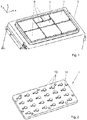
Figur 1- Isometrische Ansicht eines Bauzylinders einer additiven Fertigungsanlage mit Werkstückträgern;
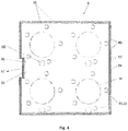
Figur 2- Isometrische Ansicht eines Grundträgers für die
Fertigungsanlage gemäß Figur 1 ; - Figur 3
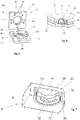
- Isometrische Ansicht von unten auf drei Ausführungsformen (3a, 3b, 3c) von
Werkstückträgern der Figur 1 ; Figur 4- Draufsicht auf einen Werkstückträger einer ersten Ausführungsform eines Trägersystems;
- Figur 5
- 3D-Ansicht eines "aufgeklappten"
Werkstückträgers gemäß Figur 4 ; Figur 6- Schnitt durch eine Anordnung des Werkstückträgers gemäß
Figur 5 auf einer Grundplatte; - Figur 7
- Schnitt durch einen Werkstückträger gemäß
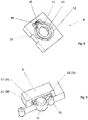
Figur 3c mit einer zweiten Ausführungsform der Positionierungseinrichtung; Figur 8- Isometrische Ansicht von unten auf einen Werkstückträger gemäß
Figur 3c mit einer dritten Ausführungsform einer Positionierungseinrichtung; - Figur 9
- Vergrößerte Darstellung von Werkstückträgern auf einer Grundplatte mit Teilschnitt durch eine Positionierungseinrichtung gemäß
Figur 8 ;
Figur 10- Schnitt durch eine Anordnung eines Werkstückträgers gemäß
Figur 4 auf einem Grundträger mit Positionierungszapfen geschnitten und ungeschnitten; und Figur 11- Ausführungsform eines Verfahren zum Herstellen eines Werkstücks nach einem Fertigungsverfahren der additiven Art.
- FIG. 1
- Isometric view of a construction cylinder of an additive manufacturing plant with workpiece carriers;
- FIG. 2
- Isometric view of a basic carrier for the manufacturing plant according to
FIG. 1 ; - FIG. 3
- Isometric view from below of three embodiments (3a, 3b, 3c) of workpiece carriers of
FIG. 1 ; - FIG. 4
- Top view of a workpiece carrier of a first embodiment of a carrier system;
- FIG. 5
- 3D view of an "unfolded" workpiece carrier according to
FIG. 4 ; - FIG. 6
- Section through an arrangement of the workpiece carrier according to
FIG. 5 on a base plate; - FIG. 7
- Section through a workpiece carrier according to
Figure 3c with a second embodiment of the positioning device; - FIG. 8
- Isometric view from below of a workpiece carrier according to
Figure 3c with a third embodiment of a positioning device; - FIG. 9
- Enlarged view of workpiece carriers on a base plate with a partial section through a positioning device according to
FIG. 8 ;
- FIG. 10
- Section through an arrangement of a workpiece carrier according to
FIG. 4 cut on a base support with positioning pins and uncut; and - FIG. 11
- Embodiment of a method for manufacturing a workpiece according to a manufacturing method of the additive type.
Die Bauplattform 4 umfasst einen Grundträger oder eine Grundplatte 6 (hier nicht sichtbar, siehe
Für die Positionierung der Paletten 8 weist der Grundträger 6 Zapfen 10 auf. An der Unterseite 12 weisen die Paletten 8 Vertiefungen 14 auf, die im Querschnitt wenigstens an einer Umfangslinie komplementär zu den Zapfen 10 ausgebildet sind, so dass die Zapfen 10 mit allenfalls geringem Widerstand, aber jedenfalls mit geringem Spiel bis praktisch spielfrei in die Ausnehmungen 14 gleiten und somit die Paletten 8 genau auf einer Position halten. Die Begriffe "Ausnehmung" und "Vertiefung" werden hierin synonym verwendet und haben im Rahmen dieser Offenbarung denselben Sinngehalt. Bei den kleinsten Paletten 16, die nur eine Ausnehmung 14 aufweisen, ist es vorteilhaft, um nicht zu sagen nötig für eine automatische Bestückung des Grundträgers 6, eine Verdrehsicherung vorzusehen. Vorliegend besteht sie in einer kleineren Verdrehsicherungsausnehmung 18 und dazu passenden Verdrehsicherungsstiften 20 in dem Grundträger 6.For the positioning of the
Die Verdrehsicherungsmaßnahmen können dabei auch generell als exzentrisch zu den Zapfen 10 ausgebildete Erhebungen und entsprechende Vertiefungen in der Unterseite der Paletten 8 ausgebildet sein, wie noch erläutert wird. Alternativen dazu sind das Ausbilden der Zapfen 10 in einer anderen als kreissymmetrischen Form, z. B. mit ovalem, elliptischen oder polygonalem Querschnitt oder eine andere, den kreissymmetrischen Querschnitt störende Maßnahme wie z. B. eine radial vorspringende Nase, oder Kombinationen aus den vorgenannten Formen.The anti-rotation measures can also be formed generally as eccentric to the
Die Paletten 8 gemäß dem vorliegenden Ausführungsbeispiel zeigen wenigstens an der Oberseite 11 ein Material, auf dem mit dem additiven Fertigungsverfahren ein Werkstück erstellt werden kann. Es handelt sich also um ein Material, das zum jeweiligen Baumaterial kompatibel ist. Im Rahmen der Produktion von Werkstücken aus metallischen Pulvern ist ein solches Material z. B. eine Aluminiumlegierung. Eine weitere Schwierigkeit besteht dabei darin, dass während des Produktionsprozesses erhöhte Temperaturen auftreten. Zum Beispiel wird der Grundträger 6 auf eine Temperatur von beispielsweise 200 °C erwärmt. Dazu kommt, dass durch das Schmelzen des Baumaterials, insbesondere in der Anfangsphase, nahe der Oberfläche 11 durch den Schmelzprozess weiterer Energieeintrag erfolgt, der lokal zu Temperaturerhöhung führt. Durch diese erhöhten Temperaturen treten thermische Ausdehnungseffekte auf. Trotzdem muss jedoch wenigstens die Oberfläche der Palette hohen Anforderungen an die Maßhaltigkeit genügen. Abgesehen von Dimensionsänderungen in der xy-Ebene, also parallel zur Oberseite 11 (siehe
xy-Verschiebungen werden reduziert, indem die Ausnehmungen 14 wenigstens in dem Bereich, der für die Positionierung ausschlaggebend ist, aus einem Material mit entsprechend geringer thermischer Ausdehnung bestehen. Bevorzugt ist hierbei Werkzeugstahl, insbesondere auch warmfester Werkzeugstahl im Hinblick auf einen späteren Transfer der Paletten 8 in eine Werkzeugmaschine der spanenden Fertigung oder auch eine thermische Nachbehandlung bei hoher Temperatur wie z. B. heißisostatisches Pressen.xy shifts are reduced by having the
Die
Bei dieser Konstruktion wurde beobachtet, dass ein geringerer Temperaturgradient innerhalb des Oberteils 57 auftritt und entsprechend eine geringere Neigung zur Ausbildung einer gewölbten Oberseite auftritt. Ein anderer Faktor, der einer Wölbung entgegensteht, kann auch das Unterteil 59 sein, das als steifes und temperaturstabiles Element dem Ausbilden einer konkaven Wölbung an der Unterseite des Oberteils 57 entgegensteht. Für eine exakte relative Positionierung von Unterteil 59 und Oberteil 57 beim Zusammenbau wird ein erster Positionierungsbolzen 65 im Unterteil 59 vorgeschlagen, der in ein exakt dazu passendes erstes Positionierungsloch 67 im Oberteil 57 eingeführt werden kann. Beabstandet zum Positionierungsbolzen 65 weist das Unterteil 59 einen zweiten Positionierungsbolzen 69 auf, der zum Einführen in ein zweites Positionierungsloch 71 vorgesehen ist. Das Positionierungsloch 71 weist die Besonderheit auf, dass es in Richtung der Verbindungslinie zum ersten Positionierungsloch 67 verlängert ausgeführt ist, also einen ovalen Querschnitt aufweist oder in Form eines Langlochs bereitgestellt ist. Dadurch wird die verschiedene thermische Ausdehnung von Oberteil 57 und Unterteil 59 bei Erwärmung der Palette 8 ausgeglichen, ohne den zweiten Positionierungsbolzen 69 zu belasten. Bei größeren Paletten 8 kann es nötig werden, zusätzliche Positionierungsbolzen und -löcher vorzusehen, die gegenüber der Verbindungslinie erster Positionierungsbolzen 65 - zweiter Positionierungsbolzen 69 seitlich versetzt sind. Für diese sind dann dritte Positionierungslöcher (nicht dargestellt) vorzusehen, die einen größeren Querschnitt aufweisen als die jeweiligen Positionierungsbolzen, um eine Verschiebung in eine beliebige Richtung in der xy-Ebene zu gestatten. Ebenso sind die Löcher 63 für die Schrauben 61 im Unterteil 59 mit einem Übermaß gegenüber dem Schaft der Schrauben 61 ausgeführt, so dass sich die Schraubenköpfe der Schrauben 61 und ihr Schaft im Unterteil 59 entsprechend der relativen thermischen Ausdehnung des Oberteils 57 verschieben können.In this construction, it has been observed that a lower temperature gradient occurs within the top 57 and, correspondingly, there is less tendency for a curved top to form. Another factor that opposes a curvature, may also be the
Einen Werkstückträger 8 (Palette 8) einer zweiten Ausführungsform eines Trägersystems zeigt
Die Ausnehmung 32, die die Fassung 28 aufnimmt, wird durch eine relativ dünne Zylinderwand 36 begrenzt, die von einer Dehnungsfuge 38 umgeben ist. Die Zylinderwand 36, die auch das Gewinde 26 an der Innenseite trägt, ist dabei nötigenfalls mit einem Untermaß gegenüber dem Umfang der Fassung 28 ausgebildet, um eine gegebenenfalls höhere thermische Ausdehnung des Materials des Körpers 9 des unteren Elements gegenüber dem Material der Fassung 28 unter den Bedingungen der Fertigung auszugleichen. Insbesondere ist das Untermaß derart gewählt, dass bei der höchsten anzunehmenden Temperatur während der additiven Fertigung die Fassung 28 sicher und spielfrei im Gewinde 26 gehalten ist.The
Zu beachten bei dieser Lösung ist, dass die Fassung 28 und entsprechend die Gewinde 26 in der Palette 8 für die Fassung mit hoher Präzision ausgeführt sein müssen, da die Fassung 28 und die Verdrehsicherungsausnehmung 30 präzise positioniert sein müssen.It should be noted in this solution that the
Die Fassung 28 dient während der spanenden Bearbeitung, wo höhere Kräfte auf die Palette 8 einwirken, als Angriffsmittel für die dort üblichen Verankerungen, z. B. Zapfen mit ausfahrbaren Kugeln oder Krallen. Möglich ist auch, die Fassung 28 zu entfernen für Bearbeitungsschritte, bei denen sie stört oder denen sie nicht standhält, z. B. heißisotatisches PressenThe
In der dritten Ausführungsform gemäß
Wie im obigen zweiten Ausführungsbeispiel geschildert, besteht die Fassung 42 aus wärmefesten Werkzeugstahl und der Körper der Palette 8 aus einem Material, das als Trägermaterial für die additive Fertigung geeignet ist (beispielsweise Aluminium oder eine Aluminiumlegierung).As described in the above second embodiment, the
Bei dieser Ausführung ist zwar die Position der Verdrehsicherungsöffnung 48 vorgegeben, jedoch muss beim Einpressen der Fassung 42 auf eine genaue Positionierung in vertikaler Richtung (z-Richtung) geachtet werden. Damit diese Positionierung auch bei den höchsten auftretenden Temperaturen nicht verloren geht, muss hier zudem eine höhere Vorspannung, das heißt Untermaß der Wand 52 gegenüber der Fassung 42, vorgesehen werden, was das Material einer höheren Belastung aussetzt.Although in this embodiment the position of the
Im Übrigen gelten bezüglich Befestigung bei spanender Nachbearbeitung und Entfernen die oben zur Fassung 28 gegebenen Erläuterungen.
-
Figur 10Zapfen 10. Genauer gesagt zeigt -
Figur 10wobei ein Werkzeugträger 8 auf einem Grundträger 6mithilfe von Zapfen 10 und zugehörigen Aussparungen 14 angebracht ist.Bei dem Werkstückträger 8 kann es sich um eine der vorgenannten Ausführungsformen handeln, insbesondere um einen Werkstückträger der ersten Ausführungsform gemäß denFiguren 4-6 .Auf einem Zapfenunterteil 81 ist mittels einerSchraube 83ein Zapfendeckel 85 befestigt.Zwischen Zapfenunterteil 81 und Zapfendeckel 85ist ein Ring 87 aus einem Material mit höherer thermischer Ausdehnung (größerer Wärmeausdehnungskoeffizient) alsdas untere Element 59 desWerkstückträgers 8 des ersten Ausführungsbeispiels (wie hier dargestellt) oder dieFassungen 28 bzw. 42 der anderen Ausführungsformen eingeklemmt. Bevorzugt ist hierfür eine Aluminiumlegierung.Der Ring 87 ist insbesondere so angeordnet, dass er genau auf dieFassungen 28 bzw. 42 stößt oder, wie hier dargestellt, auf einen ringförmigen Kragen 91 des unterenElements 59. BeimAufsetzen einer Palette 8 auf einen Grundträger 6 gleiten dieZapfen 10 möglichst ohne Spiel, aber noch leichtgängig indie Ausnehmungen 14 der Paletten. Bei Temperaturerhöhungen dehnt sich derRing 87 stärker aus als das umgebende Material, wodurch die Paletten (Werkstückträger) 8 mit zunehmenderKraft am Grundträger 6 gehalten wird.
-
FIG. 10 shows a preferred embodiment of thepins 10. More specifically shows -
FIG. 10 an embodiment wherein atool carrier 8 is mounted on abase support 6 by means ofpins 10 and associated recesses 14. Theworkpiece carrier 8 may be one of the abovementioned embodiments, in particular a workpiece carrier of the first embodiment according to FIGSFigures 4-6 , On ajournal base 81, apin cover 85 is fastened by means of ascrew 83. Between spigot 81 andspigot 85, aring 87 made of a material having a higher thermal expansion (larger thermal expansion coefficient) than thelower element 59 of theworkpiece carrier 8 of the first embodiment (as shown here) or thesockets ring 87 is in particular arranged so that it abuts exactly on thesockets annular collar 91 of thelower member 59. When placing apallet 8 on abase support 6, thepins 10 slide as possible without Game, but still smooth in therecesses 14 of the pallets. In temperature increases, thering 87 expands more than the surrounding material, whereby the pallets (workpiece carrier) 8 is held with increasing force on thebase support 6.
Alternativ zu der oben geschilderten Ausführungsform der Zapfen 10 kann ein Material mit höherer thermischer Ausdehnung auch an den Rändern des Lochs vorgesehen sein. Insbesondere kann ein Halterungsabschnitt 28, 42, 91 des Lochs (14) aus einem Material mit höherem Wärmeausdehnungskoeffizient als das Material eines Abschnitts des Zapfens 10 ausgebildet sein. Im Falle der ersten Ausführungsform bedeutet dies, dass der Kragen 91 des Lochs und gegebenenfalls das gesamte untere Element 59 aus dem Material mit höherem Wärmeausdehnungskoeffizient gebildet sind. Im Falle des zweiten und dritten Ausführungsbeispiels bedeutet dies, dass die Fassung 28 bzw. die Fassung 42 aus dem Material mit höherem Wärmeausdehnungskoeffizient gebildet sind. Gemäß dieser Alternative dehnt sich das umgebende Loch 14 bei Erwärmung des Trägersystems in negative radiale Richtung zu dem Zapfen 10 hin aus, sodass die gewünschte Klemmwirkung erzielt wird.As an alternative to the above-described embodiment of the
Der Kragen 91 dient auch dem Eingriff einer Haltevorrichtung während nachfolgenden spanenden Bearbeitungsschritten analog zu den Fassungen 28 und 42. Wenn eine Bearbeitung für das Material des Unterteils ungünstig ist, wie z. B. zu hohe Temperaturen, kann das Unterteil entfernt werden.The
Gerade bei additiven Fertigungsverfahren, bei denen flächig ein Pulver schichtenweise aufgetragen wird, ist es zu vermeiden, dass sich Hohlräume oder andere Unregelmäßigkeiten in den Schichten bilden. Die Zwischenräume zwischen den Paletten 8 und der Wand des Bauzylinders 2 müssen also sicher gleichmäßig mit dem Baumaterialpulver gefüllt werden. Ein weiterer Effekt besteht in der thermischen Ausdehnung bzw. dem Schrumpfen während des Fertigungsprozesses. Beim Ausdehnen der Paletten 8 muss sichergestellt sein, dass das Baumaterialpulver aus Zwischenräumen, die sich durch diesen Prozess verkleinern, ausweichen kann. Andererseits muss auch im Falle einer Verringerung der Dimension der Paletten sichergestellt sein, dass das Pulver in einer eher dem Fließen einer Flüssigkeit entsprechenden Art die sich wieder vergrößernden Zwischenräume ausfüllen kann, so dass jedenfalls nach dem Aufbringen einer Pulverschicht und deren Glätten sicher ist, dass keine weiteren Verschiebungen oder Bewegungen im Pulver mehr vorkommen, also das System stabil ist.Especially in additive manufacturing processes in which a powder is applied layer by layer, it is to be avoided that cavities or other irregularities form in the layers. The spaces between the
Um diese Forderungen zu erfüllen, hat sich eine pyramidenstumpfartige Ausbildung der Paletten als geeignet erwiesen. Die Seitenwände der Paletten 8 der Ausführungsbeispiele sind geneigt, so dass sich die Paletten von der Unterseite 12 zur Oberseite 11 hin verjüngen. Damit ergibt sich eine Art Trichterwirkung, die einerseits das Ausweichen des Pulvers bei Verringerung der Zwischenräume zwischen den Paletten bzw. Paletten und Zylinderwand erlaubt und andererseits ein sicheres, widerstandsfreies Nachrutschen im Falle einer Vergrösserung dieser Zwischenräume sicherstellt.To meet these requirements, a truncated pyramidal design of the pallets has been found suitable. The side walls of the
Aus einer anderen Perspektive sind aus dem genannten Grund Hinterschnitte oder Hohlräume zu vermeiden. Insbesondere schließt dies Lücken zwischen Unterseite 12 der Paletten und Oberfläche des Grundträgers 6 aus, um mit einem Greifer unter eine Palette greifen zu können. Die abgeschrägten Seitenwände 95 erschweren zusätzlich das Packen der Paletten. Für einen sicheren Griff wird daher an mindestens einer Seitenwand 95 eine Greifnut 97 angebracht. Ihre Seitenwände 98 sind senkrecht, bevorzugt jedoch leicht hinterschnitten, so dass die Greifnut 97 schwalbenschwanzförmig ist und einen Halt für einen geeigneten Greifer bietet. Wegen der relativ kleinen Dimension der Greifnuten 97, ihrem nahezu senkrechten Verlauf und einem begrenzten Hinterschnitt zur Erzielung der Schwalbenschwanzform stellen sie kein Risiko für eine ungleichmäßige Pulverbeschichtung dar.From another perspective, undercuts or cavities should be avoided for the above reason. In particular, this excludes gaps between the
Eine Besonderheit insbesondere der Verfahren mit gezieltem Schmelzen von pulverförmigen Material besteht darin, dass beim Entfernen des Werkstücks auch von der Oberfläche des Bauträgers Material abgetragen wird. Bei der ersten Ausführungsform besteht in dieser Hinsicht ein weiterer Vorteil darin, dass das Oberteil 57 einfach ausgewechselt werden kann. Es ist in dieser Hinsicht sogar denkbar, dass das Oberteil 57 kleiner ausgeführt wird, so dass die Greifnut 97 nur im Unterteil 59 aus Werkzeugstahl vorhanden ist. Dadurch ist die Form des Oberteils 57 wesentlich vereinfacht, nämlich ein Pyramidenstumpf mit geraden, ununterbrochenen Seitenwänden.A special feature of the method with targeted melting of powdered material is that material is removed from the surface of the developer when removing the workpiece. In the first embodiment, another advantage in this regard is that the top 57 can be easily replaced. It is even conceivable in this regard that the
Denkbar ist in dieser Hinsicht aber auch, den Verlust an Material der Palette 8 an dem Oberteil 57 auf andere Art zu ersetzen, z. B. auch durch einen zwischengeschalteten additiven Fertigungsschritt, mit dem der Materialverlust durch ein Aufwachsen neuen Materials ausgeglichen wird.It is also conceivable in this regard to replace the loss of material of the
In den oben geschilderten Ausführungsbeispielen umfasst der Grundträger 6 mindestens einen Zapfen 10 und der Werkstückträger 8 mindestens ein Loch 14. In alternativen Ausführungsbeispielen können die Zapfen-Loch-Paare jedoch auch umgedreht angeordnet sein, sodass der Grundträger 6 mindestens ein Loch und der Werkstückträger 8 mindestens einen zugehörigen Zapfen aufweist. Die oben geschilderte Klemmwirkung wird in diesen Ausführungsbeispielen auch auf die oben geschilderte Weise erreicht. In den anderen Aspekten stimmen diese Ausführungsbeispiele mit den oben geschilderten Überein. Ferner können auch mehrere Zapfen-Loch-Paare so vorgesehen sein, dass der Grundträger 6 sowohl Zapfen als auch Löcher aufweist und dass der Werkstückträger 8 zugehörige Löcher und Zapfen aufweist.In the above-described embodiments, the
Zusammengefasst ergeben die angegebenen Paletten (Werkstückträger) 8 zusammen mit dem Grundträger 6 ein Trägersystem, bei dem es möglich ist, ein Werkstück samt Palette zwischen einer Anlage der additiven Fertigung und Anlagen zur anderweitigen Bearbeitung des Werkstücks (Spanen, Wärmebehandlung, Reinigen, Vermessen) auf einfache Art zu transportieren, insbesondere auch mittels eines Roboters. Insgesamt ergibt sich dadurch eine erhebliche Rationalisierungsmöglichkeit. Durch eine geeignete Konstruktion der Paletten wurden negative Auswirkungen, sei es durch thermische Ausdehnungen oder Gefahr ungleichmäßiger Pulverbeschichtung, vermieden. So kann in einem Prozess beispielsweise ein Werkstückträger 8 von einer Anlage (genauer gesagt von einem Grundträger 6 der Anlage) der additiven Fertigung (beispielsweise eine Strahlschmelzanlage zum selektiven Laserschmelzen) automatisiert zu einer Anlage der subtraktiven Bearbeitung des hergestellten Werkstücks transportiert werden. Optional kann in einem Zwischenschritt der Werkstückträger 8 samt Werkstück in einer Anlage zur thermischen Nachbearbeitung positioniert werden.In summary, the specified pallets (workpiece carrier) 8 together with the
Mit den hierin beschriebenen Trägersystemen der ersten bis dritten Ausführungsform kann beispielsweise ein Verfahren zum Herstellen eines Werkstücks wie folgt durchgeführt werden. Zunächst wird der Werkstückträger 8 des Trägersystems gemäß einer der Ausführungsformen auf dem Grundträger 6 des Trägersystems in einer Herstellungsvorrichtung der additiven Art angeordnet. Hierbei greift der Zapfen 10 des Grundträgers 6 in das Loch 14 des Werkstückträgers 8 ein, wie in
Nach Durchführen der additiven Fertigung kühlt das Trägersystem ab, wobei sich die Klemmwirkung wieder löst. Anschließend wird der Werkstückträger 8 zusammen mit dem darauf gefertigten Werkstück von dem Grundträger 6 gelöst und zu einer Anlage zur subtraktiven Nachbearbeitung des Werkstücks transportiert. Der Werkstückträger 8 wird auf einem Träger der Anlage zur subtraktiven Nachbearbeitung angeordnet, wobei ein Zapfen 10 des Trägers in das Loch 14 des Werkstückträgers 8 eingreift. Alternativ kann das sich auf dem Werkstückträger 8 befindliche Werkstück zwischen der additiven und der subtraktiven Fertigung einen oder mehrere Zwischenfertigungsschritte durchlaufen, wie beispielsweise eine thermische Nachbearbeitung in einer entsprechenden Anlage, welche ebenfalls - ähnlich wie die Anlagen zur additiven und zur subtraktiven Fertigung - einen Grundträger mit entsprechenden Zapfen umfasst.After performing the additive manufacturing cools the carrier system, with the clamping effect dissolves again. Subsequently, the
Beispielhaft seien Wärmebehandlungen angegeben für verschiedene für die additive Fertigung geeignete Materialien und entsprechende Palettenoberflächen:
- Aluminiumlegierung: Wärmebehandlung im Bereich ca. 200 °C bis ca. 500 °C, bevorzugt ca. 400 °C bis ca. 540 °C.
- Titanlegierungen: Wärmebehandlung im Bereich ca. 400 °C bis ca. 995 °C (abhängig vom Legierungstyp), bevorzugt ca. 480 °C bis ca. 730 °C.
- Aluminum alloy: Heat treatment in the range of about 200 ° C to about 500 ° C, preferably about 400 ° C to about 540 ° C.
- Titanium alloys: Heat treatment in the range of about 400 ° C to about 995 ° C (depending on the alloy type), preferably about 480 ° C to about 730 ° C.
Bevorzugt zeichnen sich die Paletten 8 und der Grundträger 6 durch folgende zahlenmäßige Werte aus:
- Schräge der Seitenwände 95: 1°-11°, bevorzugt 3° bis 9°, 5° bis 7°, oder etwa 6°. Größere Winkel führen insbesondere zu einer merklichen Reduktion der Fläche, die für die Fertigung zur Verfügung steht. Kleinere Winkel führen zur Blockierung des Pulvers und generell Wirkungslosigkeit. Insbesondere ist auch bei einem zu kleinen Winkel das Pulver in Zwischenräumen eingeschlossen und weicht nicht mehr nach oben aus, wenn sich diese durch thermische Ausdehnung verkleinern.
- Die Höhe des
Oberteils 57 beträgt ¼ bis ¾ der Gesamthöhe einer Palette. Bevorzugt ist jedoch eine Höhe von höchstens der Hälfte der Höhe der Palette. Die Seitenwände 98der Greifnut 97 sind jeweils um 10° bis 40°, bevorzugt 10°bis 20°, weiter bevorzugt 15°bis 20° gegenüber dem Boden der Greifnut 97 geneigt, ein bevorzugter Wert liegt bei etwa 15°. Die Tiefe der Greifnuten kann zwischen 3 mm und 6 mm liegen, ein bevorzugter Wert sind 4 mm. Als extremeUntergrenze kann von 1 mm ausgegangen werden.- Höhe der Paletten: 25 mm bis 35 mm.
- Härte der Positionierungsteile (
Fassungen Unterteil 59; eventuell auch Grundträger 6): ca. 45 bis ca. 68 HRC (Härte Rockwell C), bevorzugt ca. 50 bis ca. 55 HRC.
- Slope of side walls 95: 1 ° -11 °, preferably 3 ° to 9 °, 5 ° to 7 °, or about 6 °. Larger angles lead in particular to a noticeable reduction in the area available for production. Smaller angles lead to the blocking of the powder and generally inefficiency. In particular, even if the angle is too small, the powder is trapped in interstices and no longer deviates upward when they shrink due to thermal expansion.
- The height of the top 57 is ¼ to ¾ of the total height of a pallet. However, a height of at most half the height of the pallet is preferred.
- The
side walls 98 of the grippinggroove 97 are each inclined by 10 ° to 40 °, preferably 10 ° to 20 °, more preferably 15 ° to 20 ° relative to the bottom of the grippinggroove 97, a preferred value is about 15 °. The depth of the gripping grooves may be between 3 mm and 6 mm, a preferred value being 4 mm. The extreme lower limit can be assumed to be 1 mm. - Height of the pallets: 25 mm to 35 mm.
- Hardness of the positioning parts (
sockets lower part 59, possibly also base support 6): about 45 to about 68 HRC (hardness Rockwell C), preferably about 50 to about 55 HRC.
Aus der vorangehenden Beschreibung von Ausführungsbeispielen sind dem Fachmann Abwandlungen und Ergänzungen zugänglich, ohne den Schutzbereich der Erfindung zu verlassen, der durch die Ansprüche festgelegt ist. Denkbar sind unter anderem:
Der Grundträger 6 kann mit einem umlaufenden Rand versehen sein, der insbesondere einen Ausgleich zwischen der Bauzylinderwand, die gerundete Ecken aufweist, und den scharfen Ecken der Paletten herstellt und damit Baumaterial einspart, das ansonsten zum Ausfüllen des dadurch bedingten relativ großen Abstandes zwischen Seitenwänden der Paletten und Bauzylinderwand aufgefüllt werden müsste.Der Grundträger 6 ist integraler Bestandteil der additiven Fertigungsanlage oder als Adapterplatte ausgebildet und wird auf geeignete Art an einer vorhandenen Bauplattform der additiven Fertigungsanlage angebracht. Denkbar sind in diesem Zusammenhang lösbare oder unlösbare Verbindungen.- Die Verdrehsicherungsmaßnahmen können entfallen bei Paletten, die
mindestens 2 Positionierungsvorkehrungen (Ausnehmungen 14) aufweisen. Die Palette 8 weist mehrals eine Greifnut 97 auf, z. B. an mehr als einer Seite, bevorzugt an gegenüberliegenden Seiten, oder mehr als eineNut 97 an einer Seite. Letzteres kann vorteilhaft bei größeren Paletten sein. Denkbar ist auch, Greifnuten an Ecken der Paletten anzuordnen, das heißt mindestens eine Ecke mit einer Greifnut auszustatten.- Statt Greifnut ist die inverse Maßnahme vorhanden, nämlich eine Rippe, die zum Palettenkörper konstante Breite oder abnehmende Breite aufweist.
- In den zweiten Positionierungseinrichtungen
weist ein Langloch 71 eine um höchstens 0,4 mm grössere Länge als Breite und ein Loch mit grösserem Durchmesser ("drittes Positionierungsloch", zusätzlich oder alternativ zu Langloch 71) einen um höchstens 0,4 mm grösseren Durchmesser als das erste (Positionierungs-)Loch 67 auf.
- The
base support 6 may be provided with a peripheral edge, which in particular produces a balance between the structural cylinder wall having rounded corners, and the sharp corners of the pallets and thus saves building material, otherwise to fill the consequent relatively large distance between side walls of the pallets and cylinder wall would have to be filled. - The
base support 6 is an integral part of the additive manufacturing plant or designed as an adapter plate and is attached in a suitable manner to an existing construction platform of the additive manufacturing plant. Conceivable in this connection are detachable or insoluble compounds. - The anti-rotation measures can be omitted for pallets having at least 2 Positionierungsvorkehrungen (recesses 14).
- The
pallet 8 has more than one grippinggroove 97, z. On more than one side, preferably on opposite sides, or more than onegroove 97 on one side. The latter can be advantageous for larger pallets. It is also conceivable to arrange gripping grooves on corners of the pallets, that is to equip at least one corner with a gripping groove. - Instead of gripping groove, the inverse action is present, namely a rib which has constant width or decreasing width to the pallet body.
- In the second positioning means, a
slot 71 has a maximum length greater than 0.4 mm and a larger diameter hole ("third positioning hole", in addition to or as an alternative to slot 71) a diameter greater than 0.4 mm at most (Positioning)hole 67 on.
In
Das Verfahren gemäß
Gemäß einem ersten Schritt S1 umfasst das Verfahren ein Festlegen einer Lage und/oder einer Ausrichtung des herzustellenden Werkstücks in Bezug auf einen Werkstückträger 8, auf welchem das Werkstück additiv gefertigt wird, unter Berücksichtigung von digitalen Bauteildaten, welche eine Geometrie des Werkstücks definieren, und unter Berücksichtigung von durch eine subtraktive Nachbearbeitung des Werkstücks definierte Bedingungen. Gemäß einem zweiten Schritt S2 umfasst das Verfahren ein Durchführen der additiven Fertigung des Werkstücks auf dem Werkstückträger 8 basierend auf der festgelegten Lage und/oder Ausrichtung des Werkstücks.According to a first step S1, the method comprises determining a position and / or an orientation of the workpiece to be produced with respect to a
Im Folgenden werden weitere (teilweise optionale) Details des in
Gemäß einer Ausführungsform umfasst das Herstellungsverfahren der
- 1.) Bauteilimport aus CAD
- 2.) Konfiguration der additiven Fertigungsmaschine entsprechend dem Palettiersystem/Trägersystem
- 3.) Bauteilaufbereitung für die additive Fertigung (umfassend Schritt S1)
- 4.) Bauteilaufbereitung für die subtraktive Nachbearbeitung
- 5.) Erzeugung der notwendigen Maschinensteuerungsdateien (additiv als auch subtraktiv)
- 6.) Definition der Qualitätssicherungsmerkmale
- 7.) Anstoßen aller Fertigungsprozesse (umfassend Schritt S2)
Zu Schritt 1.) Das Verfahren startet mit dem Import eines digitalen Bauteils aus einem entsprechenden CAD (Computer Aided Design)-Programm bzw. einem damit verbundenen PLM (Product Lifecycle Management)-System. Zu diesem Zweck können sowohl native Dateiformate, Lightweight-Daten als auch neutrale Austauschformate verwendet werden. Als Beispiel seien die Formate *.prt, *.CATPart, *.step, *.igs, *.stl, JT, PVX, etc. genannt. Basierend auf dieser Geometrie folgt später die Vorbereitung des additiven Bauprozesses unter den Gesichtspunkten der subtraktiven Nachbearbeitung in Schritt 3.) Dies beinhaltet die Möglichkeit zur Variation des gegebenen CAD-Bauteils auf Basis der konkreten Nachbearbeitung (z. B. Übermaßzugabe zur Realisierung der Nachbearbeitung).Zu Schritt 2.) Entsprechend den geometrischen Gegebenheiten des/der zu fertigenden CAD-Teils/Teile wird der mögliche Bauraum der additiven Fertigungsmaschine konfiguriert. Zur Auswahl stehen die in denAusführungsformen des Werkstückträgers 8 und desGrundträgers 6 diskutierten Größen- und Materialvarianten. Die Konfiguration des Bauraums ist entsprechend den Anforderungen der additiven Fertigung unter den Gesichtspunkten des Gasstroms, der Beschichterrichtung sowie der Scanstrategie individualisierbar. Die Konfiguration umfasst ebenso die Berücksichtigung einer automatisierten analogen Prozesskette unter Verwendung von Industrierobotern zur Prozessoptimierung (beispielsweise Ausrichtung der oben diskutierten Greifnut 97).- Zu Schritt 3.) Die Aufbereitung des Bauteils zur additiven Fertigung umfasst die Schritte der Lagedefinition der Bauteile innerhalb des Bauraums (gemäß Schritt S1) und der entsprechenden Palettierung. Weiters die Definition von möglichem Stützmaterial zur additiven Fertigung des Bauteils und die Definition der Belichtungsstrategie sowie der Schichtdicke des additiven Fertigungsprozesses.
- a.) Lagedefinition: Die Orientierung des Bauteils im Bauraum der Maschine ist unter den Gesichtspunkten der subtraktiven Nachbearbeitung zu definieren. Berücksichtigung finden die subtraktiven Bearbeitungsschritte (z. B. Senken, Bohren, Planen, Schruppen, Gewindebohren etc.), die zur Realisierung dieser Nachbearbeitung notwendigen konkreten Werkzeuge und daraus entstehende Randbedingungen wie Fräskräfte/-momente, Schwingungen etc. Dies erfolgt unter Miteinbeziehung der Verwendung findenden Materialien. Die Bereitstellung dieser Informationen kann sowohl manuell als auch automatisiert auf Basis von vom Bediener bereitgestellten internen Strategien, Datenbanken o. ä. erfolgen. Zur optimalen Orientierung der Werkstücke im Bauraum wird auf Basis der definierten subtraktiven Werkzeuge eine
Erreichbarkeitsanalyse der zu bearbeitenden Bereiche durchgeführt. Diese beinhaltet u. a. die Faktoren Maschinenkinematik, Werkzeuggeometrie, Werkzeuganbindung etc. Dem Bediener wird die Güte einzelner Orientierungen im Bauraum in Form einer Falschfarbendarstellung visualisiert. Diese Darstellung ist darüber hinaus mit weiteren Gütekriterien betreffend Bauteilverzug, minimalem Stützgeometrieaufwand, additive Bauzeit etc. kombinierbar und individuell gewichtbar. - b.) Stützmaterial: Auf Basis der definierten subtraktiven Bearbeitungsschritte erfolgt die Berechnung einer geeigneten Stützgeometrie. Diese ist so ausgeführt, dass auftretende Kräfte, Momente, Schwingungen etc. entsprechend aufgenommen und ertragen werden. Die Gewichtung erfolgt erneut unter den Gesichtspunkten einer Minimierung des Stützgeometrieaufwands. Anwendung findende Strategien umfassen die simulative Ermittlung auf Basis von Topologieoptimierung sowie machine-learning Prozesse auf Basis ausgewerteter vorangegangener Fertigungsprozesse.
- c.) Belichtungsstrategie und Schichtdicke des additiven Fertigungsprozesses: Die Erzeugung der einzelnen Schichten und der dazugehörenden Belichtungsstrategie umfasst die definierten subtraktiven Bearbeitungsschritte. Dies ermöglicht die lokale Adaption der gewonnenen Materialeigenschaften des additiv gefertigten Werkstücks zur einfacheren subtraktiven Nachbearbeitung. Der entsprechende Nutzen liegt in der schonenden Entfernung von Stützmaterial sowie in einer qualitativ hochwertigen Aufbereitung des Volumens für hochpräzise Nachbearbeitungen.
- a.) Lagedefinition: Die Orientierung des Bauteils im Bauraum der Maschine ist unter den Gesichtspunkten der subtraktiven Nachbearbeitung zu definieren. Berücksichtigung finden die subtraktiven Bearbeitungsschritte (z. B. Senken, Bohren, Planen, Schruppen, Gewindebohren etc.), die zur Realisierung dieser Nachbearbeitung notwendigen konkreten Werkzeuge und daraus entstehende Randbedingungen wie Fräskräfte/-momente, Schwingungen etc. Dies erfolgt unter Miteinbeziehung der Verwendung findenden Materialien. Die Bereitstellung dieser Informationen kann sowohl manuell als auch automatisiert auf Basis von vom Bediener bereitgestellten internen Strategien, Datenbanken o. ä. erfolgen. Zur optimalen Orientierung der Werkstücke im Bauraum wird auf Basis der definierten subtraktiven Werkzeuge eine
Zu Schritt 4.) Nach Definition der additiven Fertigungsschritte erfolgt die Definition der CAM (Computer Aided Manufacturing)-Bahnen entsprechend bekannter Strategien. Zu diesem Zweck wird auf die gewählte Orientierung des additiven Werkstücks und die definierte Werkzeugliste zurückgegriffen. Der resultierende Verfahrweg der einzelnen Bearbeitungsbahnen wird auf Validität geprüft und als neutraler G-Code erzeugt.- Zu Schritt 5.) Basierend auf den definierten additiven als auch subtraktiven Bearbeitungsschritten werden die entsprechende Maschinensteuerungsdateien erzeugt. Dies umfasst sowohl die Erstellung der Baudatei für die entsprechende additive Fertigungsmaschine als auch die Übersetzung des neutralen G-Codes in das notwendige Format der jeweiligen subtraktiven Bearbeitungsmaschine bzw. deren Steuerungssystem. Die Definition dieser Schritte ist nicht auf subtraktive Nachbearbeitungen reduziert, sondern kann in analoger Weise auf taktile oder optische Messverfahren Anwendung finden. Dadurch erlaubt dieser Prozessschritt sowohl die Definition der Nachbearbeitung als auch die Definition automatisierter Qualitätssicherungsmaßnahmen.
Zu Schritt 6.) Neben den vorangegangenen Schritten ist auch eine Definition weiterer Qualitätssicherungsmerkmale möglich. Dies umfasst:- a.) Die Definition einer eindeutigen Zuordnung der jeweiligen Bauteile bzw. Paletten/Werktstückträger zu einzelnen Fertigungsaufträgen in Form einer eindeutigen Kennzeichnung mittels QR-Code, Gefügeadaption etc.
- b.) Die Sammlung und Auswertung prozessrelevanter Sensordaten (analog, digital, optisch etc.) zur begleitenden Überwachung der additiven Fertigung und der resultierenden Bauteilgüte.
- c.) Die Definition von Messpunkten zur automatisierten Vermessung des additiv gefertigten Rohlings. Diese Messung resultiert, in Verbindung mit einem Abgleich zum digitalen Soll, in einer Rekalibrierung der subtraktiven Nachbearbeitung, sofern nötig.
- Zu Schritt 7.) Schließlich wird die Fertigung begonnen und gemäß Schritt S2 zunächst das additive Fertigungsverfahren (z. B. selektives Strahlschmelzen) durchgeführt. Hierzu werden die zuvor festgelegten Daten verwendet. Anschließend folgt optional ein thermischer Nachbehandlungsschritt und schließlich mindestens ein subtraktiver Nachbehandlungsschritt des Werkstücks. In einem Ausführungsbeispiel bleibt das Werkstück während der additiven Fertigung und während der subtraktiven Nachbearbeitung auf einem Werkstückträger. Hierbei kann es sich um einen der zuvor beschriebenen Werkstückträger der ersten bis dritten Ausführungsform handeln.
- 1.) Component import from CAD
- 2.) Configuration of the additive manufacturing machine according to the palletizing system / carrier system
- 3.) Component processing for additive manufacturing (comprising step S1)
- 4.) Component preparation for subtractive post-processing
- 5.) Generation of the necessary machine control files (additive as well as subtractive)
- 6.) Definition of quality assurance features
- 7.) triggering of all manufacturing processes (comprising step S2)
- To
step 1.) The process starts with the import of a digital part from a corresponding CAD (Computer Aided Design) program or an associated PLM (Product Lifecycle Management) system. Both native file formats, lightweight data and neutral exchange formats can be used for this purpose. As an example the formats * .prt, * .CATPart, * .step, * .igs, * .stl, JT, PVX, etc. are mentioned. Based on this geometry, the preparation of the additive construction process follows from the point of view of the subtractive post-processing in step 3.) This includes the possibility of varying the given CAD component based on the specific post-processing (eg oversize allowance for the realization of post-processing). - To
step 2.) According to the geometric conditions of the / to be produced CAD part / parts of the possible space of the additive manufacturing machine is configured. For selection are discussed in the embodiments of theworkpiece carrier 8 and thebase support 6 sizes and material variants. The configuration of the installation space can be customized according to the requirements of additive manufacturing from the point of view of the gas flow, the coating direction and the scanning strategy. The configuration also includes consideration of an automated analog process chain using industrial robots for process optimization (eg, alignment of the above-discussed gripping groove 97). - To step 3.) The preparation of the component for additive manufacturing comprises the steps of the position definition of the components within the installation space (according to step S1) and the corresponding palletizing. Furthermore, the definition of possible support material for the additive production of the component and the definition of the exposure strategy and the layer thickness of the additive manufacturing process.
- a.) Location definition: The orientation of the component in the installation space of the machine must be defined under the aspects of subtractive post-processing. Consideration is given to the subtractive processing steps (eg countersinking, drilling, planing, roughing, tapping, etc.), the concrete tools necessary for realizing this post-processing, and the resulting boundary conditions, such as milling forces / moments, vibrations, etc. This is done by including the use finding materials. The provision of this information can be done both manually and automatically based on operator-provided internal policies, databases, or the like. For optimum orientation of the workpieces in the installation space is based on the defined subtractive tools a
Accessibility analysis of the areas to be worked on. Among other things, this includes the factors machine kinematics, tool geometry, tool connection, etc. The quality of individual orientations in the installation space is visualized in the form of a false-color representation. In addition, this representation can be combined with other quality criteria relating to component distortion, minimal support geometry expenditure, additive construction time, etc. and weighted individually. - b.) Support material: On the basis of the defined subtractive processing steps, the calculation of a suitable support geometry is carried out. This is designed so that occurring forces, moments, vibrations, etc. are recorded and endured accordingly. The weighting is again from the viewpoint of minimizing the supporting geometry effort. Applying strategies include simulative determination based on topology optimization and machine-learning processes based on evaluated previous manufacturing processes.
- c.) Exposure strategy and layer thickness of the additive manufacturing process: The generation of the individual layers and the associated exposure strategy comprises the defined subtractive processing steps. This allows the local adaptation of the obtained material properties of the additively manufactured workpiece for easier subtractive finishing. The corresponding benefit lies in the gentle removal of supporting material as well as in a high-quality treatment of the volume for high-precision finishing.
- a.) Location definition: The orientation of the component in the installation space of the machine must be defined under the aspects of subtractive post-processing. Consideration is given to the subtractive processing steps (eg countersinking, drilling, planing, roughing, tapping, etc.), the concrete tools necessary for realizing this post-processing, and the resulting boundary conditions, such as milling forces / moments, vibrations, etc. This is done by including the use finding materials. The provision of this information can be done both manually and automatically based on operator-provided internal policies, databases, or the like. For optimum orientation of the workpieces in the installation space is based on the defined subtractive tools a
- To
step 4.) After definition of the additive manufacturing steps, the definition of the CAM (Computer Aided Manufacturing) paths takes place in accordance with known strategies. For this purpose, the selected orientation of the additive workpiece and the defined tool list are used. The resulting travel path of the individual machining paths is checked for validity and generated as a neutral G code. - To step 5.) Based on the defined additive as well as subtractive processing steps, the corresponding machine control files are generated. This includes both the preparation of the construction file for the corresponding additive manufacturing machine and the translation of the neutral G-code into the required format of the respective subtractive processing machine or its control system. The definition of these steps is not reduced to subtractive post-processing, but can be applied analogously to tactile or optical measuring methods. Thus, this process step allows both the definition of Post-processing as well as the definition of automated quality assurance measures.
- To
step 6.) In addition to the previous steps, a definition of further quality assurance features is possible. This includes:- a.) The definition of an unambiguous assignment of the respective components or pallets / workpiece carrier to individual production orders in the form of a clear identification by means of QR code, microstructure adaptation, etc.
- b.) The collection and evaluation of process-relevant sensor data (analog, digital, optical, etc.) for the accompanying monitoring of additive manufacturing and the resulting component quality.
- c.) The definition of measurement points for the automated measurement of the additive manufactured blank. This measurement, in conjunction with an adjustment to the digital target, results in a recalibration of the subtractive post-processing, if necessary.
- To step 7.) Finally, the production is started and, according to step S2, first the additive manufacturing process (eg selective jet melting) is carried out. The previously defined data will be used for this. This is optionally followed by a thermal post-treatment step and finally at least one subtractive post-treatment step of the workpiece. In one embodiment, the workpiece remains on a workpiece carrier during additive manufacturing and during subtractive post-processing. This may be one of the previously described workpiece carriers of the first to third embodiments.
Durch das oben beschriebene Verfahren gemäß
Das oben beschriebene Verfahren reduziert somit den administrativen und operativen Aufwand. Ebenso reduziert sich der regulative Aufwand im Sinne einer Validierung nach Richtlinien der z. B. Luftfahrt oder Medizintechnik etc. auf eine Gesamtintegrationskette.The method described above thus reduces the administrative and operational costs. Likewise, the regulatory effort is reduced in terms of validation according to guidelines of z. As aviation or medical technology, etc. on a total integration chain.
Claims (26)
auf dem Werkstückträger nach einem additiven Herstellungsverfahren umfassend schichtweises Auftragen eines pulverförmigen Rohmaterials ein Werkstück herstellbar ist,
der Werkstückträger (8) eine Unterseite (12) und eine der Unterseite (12) im Wesentlichen gegenüberliegende Bauseite als Oberseite (11) aufweist,
der Werkstückträger (8) an seiner Unterseite (12) mindestens eine der ersten Positionierungseinrichtungen (14) zur positionsgenauen, lösbaren Anbringung an dem Grundträger (6) der Herstellungsvorrichtung aufweist, und
der Werkstückträger (8) ein plattenförmiges oberes Element (57) und ein plattenförmiges unteres Element (59) umfasst,
das obere Element die Oberseite (11) umfasst und das untere Element (59) die Unterseite (12) umfasst, und
das obere Element (57) aus einem anderen Material gebildet ist als das untere Element (59).Workpiece carrier (8) for a carrier system according to claim 1, wherein
on the workpiece carrier according to an additive manufacturing method comprising layer-wise application of a powdery raw material, a workpiece can be produced,
the workpiece carrier (8) has a lower side (12) and a side of the building substantially opposite the lower side (12) as the upper side (11),
the workpiece carrier (8) has on its underside (12) at least one of the first positioning means (14) for positionally accurate, detachable attachment to the base support (6) of the production apparatus, and
the workpiece carrier (8) comprises a plate-shaped upper element (57) and a plate-shaped lower element (59),
the upper element comprises the upper side (11) and the lower element (59) comprises the lower side (12), and
the upper member (57) is formed of a different material than the lower member (59).
auf dem Werkstückträger nach einem additiven Herstellungsverfahren umfassend schichtweises Auftragen eines pulverförmigen Rohmaterials ein Werkstück herstellbar ist,
der Werkstückträger (8) eine Unterseite (12) und eine der Unterseite (12) im Wesentlichen gegenüberliegende Bauseite als Oberseite (11) aufweist,
der Werkstückträger (8) an seiner Unterseite (12) mindestens eine der ersten Positionierungseinrichtungen (14) zur positionsgenauen, lösbaren Anbringung an dem Grundträger (6) der Herstellungsvorrichtung aufweist, und
die Oberseite (11) wenigstens an der Oberfläche aus einem Bauträgermaterial besteht, das mit einem Bauteilmaterial des additiven Herstellungsverfahrens verträglich ist, so dass auf dem Werkstückträger (8) ein Werkstück additiv aus dem Baumaterial und verbunden mit der Oberfläche der Oberseite herstellbar ist und der Werkstückträger (8) mit dem Werkstück von dem Grundträger (6) abnehmbar ist.Workpiece carrier (8) according to claim 2 or for a carrier system according to claim 1, wherein
on the workpiece carrier according to an additive manufacturing method comprising layer-wise application of a powdery raw material, a workpiece can be produced,
the workpiece carrier (8) has a lower side (12) and a side of the building substantially opposite the lower side (12) as the upper side (11),
the workpiece carrier (8) has on its underside (12) at least one of the first positioning means (14) for positionally accurate, detachable attachment to the base support (6) of the production apparatus, and
the upper side (11) at least on the surface of a developer material is compatible with a component material of the additive manufacturing process, so that on the workpiece carrier (8) a workpiece additive from the building material and connected to the surface of the upper side is produced and the workpiece carrier (8) with the workpiece from the base support (6) is removable.
Priority Applications (7)
| Application Number | Priority Date | Filing Date | Title |
|---|---|---|---|
| EP17201412.8A EP3482911A1 (en) | 2017-11-13 | 2017-11-13 | Support system for a transport system and workpiece holder for same |
| EP18796471.3A EP3710229A1 (en) | 2017-11-13 | 2018-11-08 | Support system for a production system, and workpiece holder for same |
| PCT/EP2018/080600 WO2019092098A1 (en) | 2017-11-13 | 2018-11-08 | Support system for a production system, and workpiece holder for same |
| US16/763,662 US20200361141A1 (en) | 2017-11-13 | 2018-11-08 | Support system for a production system, and workpiece holder for same |
| JP2020544123A JP7328980B2 (en) | 2017-11-13 | 2018-11-08 | Support system for production system and its workpiece holder |
| JP2022010214A JP7259098B2 (en) | 2017-11-13 | 2022-01-26 | Support system for production system and its workpiece holder |
| JP2023061148A JP2023085446A (en) | 2017-11-13 | 2023-04-05 | Support system for production system and workpiece holder therefor |
Applications Claiming Priority (1)
| Application Number | Priority Date | Filing Date | Title |
|---|---|---|---|
| EP17201412.8A EP3482911A1 (en) | 2017-11-13 | 2017-11-13 | Support system for a transport system and workpiece holder for same |
Publications (1)
| Publication Number | Publication Date |
|---|---|
| EP3482911A1 true EP3482911A1 (en) | 2019-05-15 |
Family
ID=60302007
Family Applications (2)
| Application Number | Title | Priority Date | Filing Date |
|---|---|---|---|
| EP17201412.8A Withdrawn EP3482911A1 (en) | 2017-11-13 | 2017-11-13 | Support system for a transport system and workpiece holder for same |
| EP18796471.3A Pending EP3710229A1 (en) | 2017-11-13 | 2018-11-08 | Support system for a production system, and workpiece holder for same |
Family Applications After (1)
| Application Number | Title | Priority Date | Filing Date |
|---|---|---|---|
| EP18796471.3A Pending EP3710229A1 (en) | 2017-11-13 | 2018-11-08 | Support system for a production system, and workpiece holder for same |
Country Status (4)
| Country | Link |
|---|---|
| US (1) | US20200361141A1 (en) |
| EP (2) | EP3482911A1 (en) |
| JP (3) | JP7328980B2 (en) |
| WO (1) | WO2019092098A1 (en) |
Cited By (4)
| Publication number | Priority date | Publication date | Assignee | Title |
|---|---|---|---|---|
| WO2021165145A1 (en) * | 2020-02-17 | 2021-08-26 | Realizer Gmbh | Calibration of a system for selective powder melting |
| US20210260836A1 (en) * | 2020-02-26 | 2021-08-26 | Seiko Epson Corporation | Three-dimensional shaping system and three-dimensional shaped object manufacturing method |
| EP3967427A1 (en) * | 2020-09-09 | 2022-03-16 | Peter Lehmann AG | Construction platform device |
| CN114406669A (en) * | 2022-02-09 | 2022-04-29 | 苏州天准科技股份有限公司 | Method for assembling a desiccant in a heat exchanger of a motor vehicle |
Families Citing this family (4)
| Publication number | Priority date | Publication date | Assignee | Title |
|---|---|---|---|---|
| DE102020121430A1 (en) | 2020-08-14 | 2022-02-17 | Lixil Corporation | Device and method for the additive manufacturing of a workpiece |
| JP2022086362A (en) * | 2020-11-30 | 2022-06-09 | 株式会社Screenホールディングス | Substrate processing device and substrate processing method |
| KR20230027574A (en) * | 2021-08-19 | 2023-02-28 | 한화정밀기계 주식회사 | Machine tool |
| US20230294175A1 (en) * | 2022-03-15 | 2023-09-21 | Hamilton Sundstrand Corporation | Method of building additively on a billet substrate |
Citations (5)
| Publication number | Priority date | Publication date | Assignee | Title |
|---|---|---|---|---|
| EP1614501A2 (en) * | 2004-07-07 | 2006-01-11 | OTTO BILZ Werkzeugfabrik GmbH & Co. | Method for thermically deforming a tool holder |
| EP2386404A1 (en) | 2010-05-11 | 2011-11-16 | SLM Solutions GmbH | Device for manufacturing workpieces by applying powder layers with electromagnetic radiation or particle radiation |
| US20140191439A1 (en) * | 2013-01-04 | 2014-07-10 | New York University | Continuous Feed 3D Manufacturing |
| US20150335434A1 (en) * | 2014-05-23 | 2015-11-26 | Titan Spine, Llc | Additive and Subtractive Manufacturing Process for Producing Implants with Homogeneous Body Substantially Free of Pores and Inclusions |
| WO2016184994A1 (en) * | 2015-05-19 | 2016-11-24 | Addifab Aps | Apparatus and method for release of additively manufactured products and build platform |
Family Cites Families (6)
| Publication number | Priority date | Publication date | Assignee | Title |
|---|---|---|---|---|
| JP4304965B2 (en) * | 2002-11-11 | 2009-07-29 | トヨタ自動車株式会社 | Laminated modeling apparatus and manufacturing method |
| JP5119123B2 (en) | 2008-10-22 | 2013-01-16 | パナソニック株式会社 | Manufacturing method of three-dimensional shaped object |
| US9597730B2 (en) * | 2013-04-19 | 2017-03-21 | United Technologies Corporation | Build plate and apparatus for additive manufacturing |
| US20200238615A1 (en) * | 2015-09-25 | 2020-07-30 | Addifab Aps | Additive manufacturing device and system, modular build platform and build platform unit |
| JP2018171775A (en) | 2017-03-31 | 2018-11-08 | キヤノン株式会社 | Molding apparatus and molding method |
| CN206840725U (en) | 2017-06-09 | 2018-01-05 | 大庆市多维时空科技有限公司 | A kind of 3D printer print platform of high stability |
-
2017
- 2017-11-13 EP EP17201412.8A patent/EP3482911A1/en not_active Withdrawn
-
2018
- 2018-11-08 JP JP2020544123A patent/JP7328980B2/en active Active
- 2018-11-08 US US16/763,662 patent/US20200361141A1/en active Pending
- 2018-11-08 WO PCT/EP2018/080600 patent/WO2019092098A1/en unknown
- 2018-11-08 EP EP18796471.3A patent/EP3710229A1/en active Pending
-
2022
- 2022-01-26 JP JP2022010214A patent/JP7259098B2/en active Active
-
2023
- 2023-04-05 JP JP2023061148A patent/JP2023085446A/en active Pending
Patent Citations (5)
| Publication number | Priority date | Publication date | Assignee | Title |
|---|---|---|---|---|
| EP1614501A2 (en) * | 2004-07-07 | 2006-01-11 | OTTO BILZ Werkzeugfabrik GmbH & Co. | Method for thermically deforming a tool holder |
| EP2386404A1 (en) | 2010-05-11 | 2011-11-16 | SLM Solutions GmbH | Device for manufacturing workpieces by applying powder layers with electromagnetic radiation or particle radiation |
| US20140191439A1 (en) * | 2013-01-04 | 2014-07-10 | New York University | Continuous Feed 3D Manufacturing |
| US20150335434A1 (en) * | 2014-05-23 | 2015-11-26 | Titan Spine, Llc | Additive and Subtractive Manufacturing Process for Producing Implants with Homogeneous Body Substantially Free of Pores and Inclusions |
| WO2016184994A1 (en) * | 2015-05-19 | 2016-11-24 | Addifab Aps | Apparatus and method for release of additively manufactured products and build platform |
Cited By (6)
| Publication number | Priority date | Publication date | Assignee | Title |
|---|---|---|---|---|
| WO2021165145A1 (en) * | 2020-02-17 | 2021-08-26 | Realizer Gmbh | Calibration of a system for selective powder melting |
| US20210260836A1 (en) * | 2020-02-26 | 2021-08-26 | Seiko Epson Corporation | Three-dimensional shaping system and three-dimensional shaped object manufacturing method |
| CN113306135A (en) * | 2020-02-26 | 2021-08-27 | 精工爱普生株式会社 | Three-dimensional modeling system and method for manufacturing three-dimensional modeled object |
| US11559952B2 (en) | 2020-02-26 | 2023-01-24 | Seiko Epson Corporation | Three-dimensional shaping system and three-dimensional shaped object manufacturing method |
| EP3967427A1 (en) * | 2020-09-09 | 2022-03-16 | Peter Lehmann AG | Construction platform device |
| CN114406669A (en) * | 2022-02-09 | 2022-04-29 | 苏州天准科技股份有限公司 | Method for assembling a desiccant in a heat exchanger of a motor vehicle |
Also Published As
| Publication number | Publication date |
|---|---|
| WO2019092098A1 (en) | 2019-05-16 |
| JP7328980B2 (en) | 2023-08-17 |
| JP7259098B2 (en) | 2023-04-17 |
| US20200361141A1 (en) | 2020-11-19 |
| JP2022064947A (en) | 2022-04-26 |
| JP2021502281A (en) | 2021-01-28 |
| JP2023085446A (en) | 2023-06-20 |
| EP3710229A1 (en) | 2020-09-23 |
Similar Documents
| Publication | Publication Date | Title |
|---|---|---|
| EP3482911A1 (en) | Support system for a transport system and workpiece holder for same | |
| EP2300218B1 (en) | Dual method for the small-scale manufacture of products | |
| DE102007036370B3 (en) | Rapid prototyping assembly has height-adjustable platform with sockets for vertical rods or tubes | |
| EP3283985A1 (en) | Method and control command generation unit for automatic generation of control commands of a generative layer construction device | |
| EP2175799B1 (en) | Blank with encoding and method for manufacturing a dental moulded component | |
| DE102012206122A1 (en) | Multiple coil arrangement for a device for the generative production of components and corresponding manufacturing method | |
| EP3349928B1 (en) | Method and apparatus for additive manufacturing | |
| WO2014006192A1 (en) | Method and device for producing a three-dimensional object in layers | |
| DE102016225602B3 (en) | Method for processing a cutting plate and corresponding device for machining an insert | |
| EP3292988B1 (en) | Interchangeable platform support with improved temperature control | |
| EP3156164A1 (en) | Method of producing a workpiece using generative manufacturing ; corresponding workpiece | |
| EP3228415A1 (en) | Method of producing a workpiece using coating and additive manufacturing ; corresponding workpiece | |
| EP3715022B1 (en) | Process for additive manufacturing a component | |
| WO2015091941A1 (en) | Method for the production of a three-dimensional object, including magnetic fastening of the construction platform | |
| EP3655235B1 (en) | Method for additive manufacturing and substrate unit system | |
| DE10132408C2 (en) | Variable shape electrode | |
| DE102018003185A1 (en) | Method and device for producing a component | |
| EP3676675B1 (en) | Method for the additive construction of a structure and computer program product | |
| WO2019057455A1 (en) | Aligning and fixing a workpiece for a further machining process using an additive production method | |
| DE102018116314A1 (en) | Construction platform and method for the generative production of a component, in particular a medical product such as an implant | |
| EP3616806B1 (en) | Method for producing a model form core blank, a model form core and an investment casting molds and a casting method for producing a cast piece with a hollow structure | |
| EP3168327A1 (en) | Holding device for a substrate and method for coating a top surface of a substrate | |
| DE202020105794U1 (en) | Workpiece container and unpacking station | |
| DE102018124872A1 (en) | Mold system with separable, variable moldings to form a cast object for precision casting | |
| EP3416813B1 (en) | Processing tool and method for production thereof by means of a generative layer construction process |
Legal Events
| Date | Code | Title | Description |
|---|---|---|---|
| PUAI | Public reference made under article 153(3) epc to a published international application that has entered the european phase |
Free format text: ORIGINAL CODE: 0009012 |
|
| AK | Designated contracting states |
Kind code of ref document: A1 Designated state(s): AL AT BE BG CH CY CZ DE DK EE ES FI FR GB GR HR HU IE IS IT LI LT LU LV MC MK MT NL NO PL PT RO RS SE SI SK SM TR |
|
| AX | Request for extension of the european patent |
Extension state: BA ME |
|
| STAA | Information on the status of an ep patent application or granted ep patent |
Free format text: STATUS: THE APPLICATION IS DEEMED TO BE WITHDRAWN |
|
| 18D | Application deemed to be withdrawn |
Effective date: 20191116 |