EP3482022B1 - System zur befestigung eines querträgers an mindestens zwei masten in einer maststruktur für die stromübertragung oder -verteilung und verfahren zur befestigung eines solchen querträgers - Google Patents
System zur befestigung eines querträgers an mindestens zwei masten in einer maststruktur für die stromübertragung oder -verteilung und verfahren zur befestigung eines solchen querträgers Download PDFInfo
- Publication number
- EP3482022B1 EP3482022B1 EP17824607.0A EP17824607A EP3482022B1 EP 3482022 B1 EP3482022 B1 EP 3482022B1 EP 17824607 A EP17824607 A EP 17824607A EP 3482022 B1 EP3482022 B1 EP 3482022B1
- Authority
- EP
- European Patent Office
- Prior art keywords
- crossbar
- adapter
- pylons
- hollow composite
- pylon
- Prior art date
- Legal status (The legal status is an assumption and is not a legal conclusion. Google has not performed a legal analysis and makes no representation as to the accuracy of the status listed.)
- Active
Links
Images

Classifications
-
- E—FIXED CONSTRUCTIONS
- E04—BUILDING
- E04H—BUILDINGS OR LIKE STRUCTURES FOR PARTICULAR PURPOSES; SWIMMING OR SPLASH BATHS OR POOLS; MASTS; FENCING; TENTS OR CANOPIES, IN GENERAL
- E04H12/00—Towers; Masts or poles; Chimney stacks; Water-towers; Methods of erecting such structures
- E04H12/02—Structures made of specified materials
-
- E—FIXED CONSTRUCTIONS
- E04—BUILDING
- E04H—BUILDINGS OR LIKE STRUCTURES FOR PARTICULAR PURPOSES; SWIMMING OR SPLASH BATHS OR POOLS; MASTS; FENCING; TENTS OR CANOPIES, IN GENERAL
- E04H12/00—Towers; Masts or poles; Chimney stacks; Water-towers; Methods of erecting such structures
- E04H12/20—Side-supporting means therefor, e.g. using guy ropes or struts
-
- E—FIXED CONSTRUCTIONS
- E04—BUILDING
- E04H—BUILDINGS OR LIKE STRUCTURES FOR PARTICULAR PURPOSES; SWIMMING OR SPLASH BATHS OR POOLS; MASTS; FENCING; TENTS OR CANOPIES, IN GENERAL
- E04H12/00—Towers; Masts or poles; Chimney stacks; Water-towers; Methods of erecting such structures
- E04H12/24—Cross arms
-
- F—MECHANICAL ENGINEERING; LIGHTING; HEATING; WEAPONS; BLASTING
- F16—ENGINEERING ELEMENTS AND UNITS; GENERAL MEASURES FOR PRODUCING AND MAINTAINING EFFECTIVE FUNCTIONING OF MACHINES OR INSTALLATIONS; THERMAL INSULATION IN GENERAL
- F16M—FRAMES, CASINGS OR BEDS OF ENGINES, MACHINES OR APPARATUS, NOT SPECIFIC TO ENGINES, MACHINES OR APPARATUS PROVIDED FOR ELSEWHERE; STANDS; SUPPORTS
- F16M13/00—Other supports for positioning apparatus or articles; Means for steadying hand-held apparatus or articles
- F16M13/02—Other supports for positioning apparatus or articles; Means for steadying hand-held apparatus or articles for supporting on, or attaching to, an object, e.g. tree, gate, window-frame, cycle
-
- H—ELECTRICITY
- H02—GENERATION; CONVERSION OR DISTRIBUTION OF ELECTRIC POWER
- H02G—INSTALLATION OF ELECTRIC CABLES OR LINES, OR OF COMBINED OPTICAL AND ELECTRIC CABLES OR LINES
- H02G7/00—Overhead installations of electric lines or cables
- H02G7/20—Spatial arrangements or dispositions of lines or cables on poles, posts or towers
Definitions
- This invention relates to a system comprising at least two hollow composite pylons and a crossbar arranged to carry at least one conductor, wherein the crossbar is mounted to the at least two hollow composite pylons via respective adapters, wherein the at least two hollow composite pylons, the crossbar and the conductor forming components of a pylon structure for the transmission or distribution of power.
- the invention also relates to a method for attaching a crossbar to at least two hollow composite pylons.
- hollow composite pylons as the supporting element in transmission and distribution lines for power is known.
- the crossbar is attached to the composite pylon mainly in two different ways, both derived from attachment methods known from wooden pylons.
- the crossbar may be clamped against the pylon, for example by means of a stirrup or it may be carried by a bracket, which is bolted to the composite pylon. Combinations of these are also known. Both methods exhibit at least unfortunate deformations or locally great strains on the composite pylon.
- KR100770617B1 discloses an upper support mount for an electric pole to facilitate a power supplying process at a curved location using a vertical moving member as well as a horizontal moving member.
- An upper support mount for an electric pole includes a hemispherical case, a vertical moving member, and a horizontal moving member. The hemispherical case is covered on the electric pole. The case is coupled with the electric pole using plural bolts.
- the vertical moving member is moved in a vertical direction along an outer side surface of the case and fixed on a predetermined position.
- the horizontal moving member is coupled with a light arm steel and moved in a horizontal direction along an outer side surface of the vertical moving member.
- the horizontal moving member is fixed at a predetermined portion on the vertical moving member.
- a high voltage line and an electric insulator are coupled with the light arm steel.
- US3013584A , US4615154 , KR100835136B1 , KR100940122B1 , US6142434A , KR100737981B1 , DE102010020441A1 show other solutions for attaching a crossbar to a pylon according to the state of the art.
- US 2012/048613 A1 particularly discloses a crossbar attached to two pylons, the crossbar and pylons forming components of a pylon structure for the transmission or distribution of power.
- the invention relates more specifically to a system according to claim 1.
- a crossbar is placed over the hollow composite pylon.
- the crossbar may be attached to one or more hollow composite pylons.
- Axial forces from the crossbar acting in the axial direction of the composite pylon may thereby be distributed relatively evenly over the end portion of the composite pylon.
- the crossbar is pivotably attached to the adapter. This is relevant when the crossbar is attached to two or more composite pylons. The occurrence of bending stresses around the pivot axis, for example by axial displacement of the crossbar is thereby avoided where the composite pylons are deflected under the influence of wind forces, for example.
- the crossbar may be at a level of height above the composite pylon, which is advantageous both from a design point of view and a load-distribution point of view.
- the adapter is provided with a fork mount for pivotably attaching the adapter to the crossbar such that the crossbar is pivotable around an axis in the horizontal plane.
- the adapter may be at least partially rotatable around the longitudinal axis of the composite pylon in accordance with claim 2.
- the crossbar may be protected from forces arising from dissimilar loads on the conductors, for example. Such loads may otherwise result in considerable torsional forces being transmitted via the adapter.
- the adapter may include a guide which is arranged to guide the adapter into the desired position relative to the composite pylon, for example during installation work with the aid of a helicopter.
- At least the adapter or the composite pylon may include a divided slot extending along the circumference thereof.
- the slot is arranged to receive, for example, a bolt extending through the adapter and the composite pylon in a radial direction.
- the slot helps the adapter to be partially rotatable relative to the composite pylon while the adapter is held in a desired position relative to the composite pylon at the same time.
- the system may alternatively include a spreader, for example in the form of a tackle, which is attached between a second composite pylon and the crossbar after the crossbar has been attached to a first composite pylon.
- a spreader for example in the form of a tackle
- the system overcomes, among other things, installation problems arising from inaccurate alignment of the composite pylons.
- the invention relates more specifically to a method according to claim 7.
- the invention provides a simplified and favourable connection between the crossbar and the composite pylon or pylons.
- the connection has the effect of making forces in the pylon structure be reduced and distributed in a favourable way compared to that of known designs.
- the joint is assembling-friendly and requires relatively little equipment at the site of installation, which is of great value in often remote places.
- the crossbar is simultaneously connected to more than one hollow composite pylon, and comprising, before the step of sliding said adapters into or over the upper portion of the hollow composite pylons, a step of at least temporarily installing a spreader between the upper portions of the hollow composite pylons.
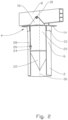
- the reference numeral 1 indicates a pylon structure comprising two hollow composite pylons 2 in the form of a first composite pylon 2a and a second composite pylon 2b, adapters 4, which are arranged at the respective upper portions 6 of the composite pylons 2, and a crossbar 8 extending between and being connected to the adapters 4.
- the composite pylons are generally indicated by the reference numeral 2, but in cases in which it is necessary to distinguish between them, the reference numerals 2a, 2b are used.
- the crossbar 8 carries three insulators 10 with respective conductors 12.
- the adapter 4 which is shown in a somewhat simplified form, includes an attachment 14 in the form of a plate resting against the upper portion 6.
- the attachment 14 is provided with a fork mount 16, which is pivotably connected to the crossbar 8 by means of a bolt 18.
- an internal body 20 here in the form of a pipe, projects into the upper portion 6 of the composite pylon 2.
- the internal body 20 is provided with a guide 22, which is arranged to facilitate the insertion of the adapter 4 into the upper portion 6.
- the internal body 20 may be provided with a slot 24 elongated in the radial direction.
- the slot 24 is arranged to receive, for example, a bolt 26 extending through a bore 28 in the upper portion 6.
- the slot 24 helps to make the internal body 20 limitedly rotatable around the longitudinal axis 30 of the composite pylon 2. It is obvious that the slot 24 may equally well be in the upper portion 6 and the bore 28 in the internal body 20.
- An external body 32 here in the form of a pipe, extends externally over the upper portion 6.
- the main function of the external body 32 is to prevent water from penetrating into the composite pylon 2.
- the external body 32 may equally well be carrying load.
- the adapter 4 thus comprises the attachment 14, the fork mount 16, the internal body 20 and the external body 32.
- the attachment 14 may be formed with connections, not shown, for diagonal struts, for example.
- the internal body 20 and the external body 32 are, in principle, freely rotatable against the upper portion 6 around the longitudinal axis 30 of the composite pylon 2.
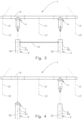
- the crossbar 8 is shown while hanging from a helicopter, not shown, and just before the adapters 4 are to be inserted into the upper portions 6 of the composite pylons 2a and 2b.
- a spreader 34 ensures that the upper portions 6 remain correctly spaced apart.
- the spreader 34 which is detachable may consist of a rod or a strap, for example, depending on whether the upper portions 6 must be moved away from each other or pulled together to take the correct distance.
- the guides 22 makes it easier to enter the upper portions 6.
- FIG 4 an alternative system for installing the crossbar 8 is shown.
- one adapter 4 has already been placed in the upper end portion 6 of the first composite pylon 2a.
- the second adapter 4, which is to be placed in the upper end portion 6 of the second composite pylon 2b is attached to the crossbar 8.
- the assembly of the crossbar 8 and adapter 4 has only to enter the upper portion 6 of the second composite pylon 2b and then be landed in the adapter 4, which is already in the upper end portion 6 of the first composite pylon 2a.
- the adapter 4 of the first composite pylon 2a may be brought into the correct position relative to the crossbar 8, for example by means of a tackle, not shown, which is connected between the adapter 4 and the crossbar 8.
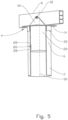
- the crossbar 8 is locked in relation to rotation around the bolt 18 and around the longitudinal axis 30 of the composite pylon 2.
- This embodiment is especially intended for a pylon structure 1 in which only one composite pylon 2 is used.
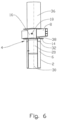
- FIG 6 an embodiment in which a body 36 projects up from the adapter 4 is shown. This embodiment is used, for example, to carry an overlying conductor, not shown.
Landscapes
- Engineering & Computer Science (AREA)
- Architecture (AREA)
- Civil Engineering (AREA)
- Structural Engineering (AREA)
- General Engineering & Computer Science (AREA)
- Materials Engineering (AREA)
- Chemical & Material Sciences (AREA)
- Wood Science & Technology (AREA)
- Life Sciences & Earth Sciences (AREA)
- Mechanical Engineering (AREA)
- Refuge Islands, Traffic Blockers, Or Guard Fence (AREA)
- Current-Collector Devices For Electrically Propelled Vehicles (AREA)
- Forklifts And Lifting Vehicles (AREA)
- Mutual Connection Of Rods And Tubes (AREA)
Claims (8)
- System, umfassend mindestens zwei hohle Verbundpylone (2a, 2b) und eine Querstange (8), die so angeordnet ist, dass sie mindestens einen Leiter (12) trägt, wobei die Querstange (8) an den mindestens zwei hohlen Verbundpylonen (2a, 2b) über jeweilige Adapter (4) montiert ist, wobei die mindestens zwei hohlen Verbundpylone (2), die Querstange (8) und der Leiter (12) Komponenten einer Pylonstruktur (1) für die Übertragung oder Verteilung von Leistung bilden,wobei jeder Adapter (4) dazu dient, die Querstange (8) an einem jeweiligen der mindestens zwei hohlen Verbundpylone (2a, 2b) zu befestigen,wobei jeder Adapter (4) in der Position der Anwendung schwenkbar an der Querstange (8) angebracht ist und zumindest in oder über den in der Position der Anwendung oberen Abschnitt (6) des jeweiligen der mindestens zwei hohlen Verbundpylone (2a, 2b) und hauptsächlich entlang der Längsachse (30) des jeweiligen der mindestens zwei hohlen Verbundpylone (2a, 2b) während eines Teils der Installationsphase gleiten kann,wobei jeder Adapter (4) mit einer Gabelhalterung (16) zum schwenkbaren Befestigen des Adapters (4) an der Querstange (8) bereitgestellt ist, wobei die Querstange (8) um eine Achse in der horizontalen Ebene schwenkbar ist.
- System nach Anspruch 1, wobei jeder Adapter (4) so gebildet ist, dass er in der Position der Anwendung zumindest teilweise um die Längsachse (30) des hohlen Verbundpylons (2) drehbar ist.
- System nach Anspruch 1 oder 2, wobei jeder Adapter (4) einen Innenkörper (20) einschließt, der komplementär in den oberen Abschnitt (6) des hohlen Verbundpylons (2) passt.
- System nach einem der vorstehenden Ansprüche, wobei jeder Adapter (4) einen Außenkörper (32) einschließt, der komplementär um den oberen Abschnitt (6) des hohlen Verbundpylons (2) passt.
- System nach einem der vorstehenden Ansprüche, wobei jeder Adapter (4) eine Führung (22) einschließt, die angeordnet ist, um den Adapter (4) in die gewünschte Position relativ zu dem hohlen Verbundpylon (2) zu führen.
- System nach einem der vorstehenden Ansprüche, wobei jeder Adapter (4) einen geteilten Schlitz (24) einschließt, der sich um seinen Umfang herum erstreckt, der angeordnet ist, um einen Bolzen (26) zu empfangen, der sich in einer Radialrichtung durch den Adapter (4) und den hohlen Verbundpylon (2) erstreckt.
- Verfahren zum Befestigen einer Querstange (8) an mindestens zwei hohlen Verbundpylonen (2a, 2b), wobei die Querstange (8) angeordnet ist, um mindestens einen Leiter (12) zu tragen, wobei die mindestens zwei hohlen Verbundpylone (2), die Querstange (8) und der Leiter (12) Komponenten einer Pylonstruktur (1) für die Übertragung oder Verteilung von Leistung bilden, dadurch gekennzeichnet, dass das Verfahren Folgendes umfasst:- Bereitstellen von Adaptern (4) zum Befestigen der Querstange (8) an den mindestens zwei hohlen Verbundpylonen (2a, 2b), wobei jeder Adapter (4) mit einer Gabelhalterung (16) zum schwenkbaren Befestigen des Adapters (4) an der Querstange (8) bereitgestellt ist, wobei die Querstange (8) um eine Achse in der horizontalen Ebene schwenkbar ist,- Gleiten jedes Adapters (4) zumindest in oder über den oberen Abschnitt (6) des jeweiligen der mindestens zwei hohlen Verbundpylone (2a, 2b) und hauptsächlich entlang der Längsachse (30) des jeweiligen der mindestens zwei hohlen Verbundpylone (2a, 2b), und- schwenkbares Befestigen jedes Adapters (4) an der Querstange (8).
- Verfahren nach Anspruch 7, wobei das Verfahren vor dem Schritt des Gleitens der Adapter (4) in oder über die oberen Abschnitte (6) der hohlen Verbundpylone (2a, 2b) einen Schritt des zumindest vorübergehenden Installierens eines Spreizers (34) zwischen den oberen Abschnitten (6) der hohlen Verbundpylone (2a, 2b) umfasst.
Applications Claiming Priority (2)
| Application Number | Priority Date | Filing Date | Title |
|---|---|---|---|
| NO20161131A NO343369B1 (no) | 2016-07-07 | 2016-07-07 | Anordning for innfesting av en travers til en hul komposittmast, samt system omfattende slike traverser og fremgangsmåte for innfesting av en slik travers. |
| PCT/NO2017/050177 WO2018009074A1 (en) | 2016-07-07 | 2017-07-04 | Overlying cross bar fastener |
Publications (4)
| Publication Number | Publication Date |
|---|---|
| EP3482022A1 EP3482022A1 (de) | 2019-05-15 |
| EP3482022A4 EP3482022A4 (de) | 2020-03-25 |
| EP3482022C0 EP3482022C0 (de) | 2024-08-07 |
| EP3482022B1 true EP3482022B1 (de) | 2024-08-07 |
Family
ID=60913001
Family Applications (1)
| Application Number | Title | Priority Date | Filing Date |
|---|---|---|---|
| EP17824607.0A Active EP3482022B1 (de) | 2016-07-07 | 2017-07-04 | System zur befestigung eines querträgers an mindestens zwei masten in einer maststruktur für die stromübertragung oder -verteilung und verfahren zur befestigung eines solchen querträgers |
Country Status (6)
| Country | Link |
|---|---|
| US (1) | US10781600B2 (de) |
| EP (1) | EP3482022B1 (de) |
| AU (1) | AU2017291639B2 (de) |
| CA (1) | CA3029795C (de) |
| NO (1) | NO343369B1 (de) |
| WO (1) | WO2018009074A1 (de) |
Citations (8)
| Publication number | Priority date | Publication date | Assignee | Title |
|---|---|---|---|---|
| US5157882A (en) * | 1990-04-27 | 1992-10-27 | Soble Bernard D | Pole support system for a carport and the like |
| US6142434A (en) * | 1997-07-01 | 2000-11-07 | Trost; Michael D. | Utility pole clamp |
| KR100737981B1 (ko) * | 2007-02-13 | 2007-07-10 | 유한회사 기봉 | 케이블 선로 가변기능을 갖는 배전탑 |
| KR100770617B1 (ko) * | 2007-08-14 | 2007-10-26 | 박혜숙 | 가공배전용 전주 상부지지대 |
| KR100835136B1 (ko) * | 2008-03-10 | 2008-06-04 | 주식회사 인창이엔지 | 전선케이블용 경완금 연결장치 |
| KR100940122B1 (ko) * | 2009-09-15 | 2010-02-03 | (주)전우엔지니어링 | 특고압 배전선 고정용 완철 |
| US20100155537A1 (en) * | 2008-12-23 | 2010-06-24 | Spirit Aerosystems, Inc. | Energy-absorbing structural composite element |
| DE102010020441A1 (de) * | 2010-05-12 | 2011-11-17 | Electro Wind Power South India Pvt. Ltd. | Photovoltaik-Anlage |
Family Cites Families (26)
| Publication number | Priority date | Publication date | Assignee | Title |
|---|---|---|---|---|
| US689387A (en) * | 1901-06-24 | 1901-12-24 | William B Crossland | Sectional electric light, telephone, or telegraph pole. |
| US2075700A (en) * | 1934-01-03 | 1937-03-30 | Brown Co | Structural element |
| US2610818A (en) * | 1950-06-10 | 1952-09-16 | Slater N Co Ltd | Crossarm clevis |
| US3013584A (en) * | 1955-03-28 | 1961-12-19 | Gar Wood Ind Inc | Supporting members |
| US4615154A (en) * | 1985-06-28 | 1986-10-07 | Trus Joist Corporation | Utility line transmission tower apparatus |
| US4932623A (en) * | 1988-05-06 | 1990-06-12 | Hughes Brothers, Inc. | Bracket |
| US5605017A (en) * | 1994-01-13 | 1997-02-25 | Pupi Enterprises L.L.C. | Pultruded utility line support structure and method |
| US6250596B1 (en) * | 1998-05-13 | 2001-06-26 | Musco Corporation | Spacer between pole and cross-arm |
| US6116556A (en) | 1999-02-05 | 2000-09-12 | C. E. W. Lighting, Inc. | Multi-mount for lighting and pole accessories |
| US6202964B1 (en) * | 1999-06-28 | 2001-03-20 | Dalbert Thornhill | Multi-purpose hanger |
| US6626406B1 (en) * | 2000-10-03 | 2003-09-30 | Ted Olson, Jr. | Utility pole with removable crossarm |
| US6520462B2 (en) * | 2001-03-16 | 2003-02-18 | American Electric Power Company, Inc. | Temporary arm support |
| PL1724892T3 (pl) * | 2003-08-29 | 2017-01-31 | Quanta Services | Przeciąganie przewodu pod napięciem i sposoby łączenia przez splatanie |
| US8397350B2 (en) * | 2009-10-07 | 2013-03-19 | Line Control Systems, LLC | Fastening method and apparatus |
| US8375650B2 (en) * | 2009-10-09 | 2013-02-19 | International Towers, Inc. | Rapid deployable structure for remote installation |
| BR112013004499A8 (pt) * | 2010-08-26 | 2017-10-17 | Acronimus Tech S L Es | kit para montar um ou mais equipamentos em um poste |
| US8652629B2 (en) * | 2010-08-31 | 2014-02-18 | Frp Transmission Innovations Inc. | Transmission cross arm |
| US9016022B2 (en) * | 2011-02-11 | 2015-04-28 | Trinity Industries Inc. | Support apparatus for supporting utility cables and utility transmission line including same |
| CN102296866B (zh) | 2011-05-31 | 2013-02-06 | 武汉理工大学 | 复合材料输电杆塔横担和杆体的安装连接方法 |
| US9912135B2 (en) * | 2013-09-17 | 2018-03-06 | San Diego Gas & Electric Company | Cross arm covers for utility poles and related methods |
| CN104453332A (zh) * | 2013-09-22 | 2015-03-25 | 国家电网公司 | 输电杆塔 |
| NO337585B1 (no) * | 2013-12-09 | 2016-05-09 | Hallingmast As | Innretning for hurtig og kontrollert skjøting av en mast. |
| US9526928B2 (en) * | 2014-04-21 | 2016-12-27 | William D. Putzer | Fall protection system |
| US9702162B2 (en) * | 2015-02-06 | 2017-07-11 | Trident Industries, LLC | Pultruded or extruded cross arm structures for utility poles |
| US11047147B2 (en) * | 2017-05-15 | 2021-06-29 | Maclean Power, Llc | L-shaped crossarm, related system, and method of assembly |
| CA3081110A1 (en) * | 2017-11-26 | 2019-05-31 | Ampjack Industries Ltd. | Utility tower leveling apparatus and method |
-
2016
- 2016-07-07 NO NO20161131A patent/NO343369B1/no unknown
-
2017
- 2017-07-04 CA CA3029795A patent/CA3029795C/en active Active
- 2017-07-04 EP EP17824607.0A patent/EP3482022B1/de active Active
- 2017-07-04 WO PCT/NO2017/050177 patent/WO2018009074A1/en not_active Ceased
- 2017-07-04 US US16/308,605 patent/US10781600B2/en active Active
- 2017-07-04 AU AU2017291639A patent/AU2017291639B2/en active Active
Patent Citations (8)
| Publication number | Priority date | Publication date | Assignee | Title |
|---|---|---|---|---|
| US5157882A (en) * | 1990-04-27 | 1992-10-27 | Soble Bernard D | Pole support system for a carport and the like |
| US6142434A (en) * | 1997-07-01 | 2000-11-07 | Trost; Michael D. | Utility pole clamp |
| KR100737981B1 (ko) * | 2007-02-13 | 2007-07-10 | 유한회사 기봉 | 케이블 선로 가변기능을 갖는 배전탑 |
| KR100770617B1 (ko) * | 2007-08-14 | 2007-10-26 | 박혜숙 | 가공배전용 전주 상부지지대 |
| KR100835136B1 (ko) * | 2008-03-10 | 2008-06-04 | 주식회사 인창이엔지 | 전선케이블용 경완금 연결장치 |
| US20100155537A1 (en) * | 2008-12-23 | 2010-06-24 | Spirit Aerosystems, Inc. | Energy-absorbing structural composite element |
| KR100940122B1 (ko) * | 2009-09-15 | 2010-02-03 | (주)전우엔지니어링 | 특고압 배전선 고정용 완철 |
| DE102010020441A1 (de) * | 2010-05-12 | 2011-11-17 | Electro Wind Power South India Pvt. Ltd. | Photovoltaik-Anlage |
Also Published As
| Publication number | Publication date |
|---|---|
| EP3482022C0 (de) | 2024-08-07 |
| EP3482022A1 (de) | 2019-05-15 |
| CA3029795C (en) | 2025-05-06 |
| NO20161131A1 (no) | 2018-01-08 |
| NO343369B1 (no) | 2019-02-11 |
| WO2018009074A1 (en) | 2018-01-11 |
| NZ749035A (en) | 2021-10-29 |
| US20190153742A1 (en) | 2019-05-23 |
| AU2017291639B2 (en) | 2019-12-19 |
| US10781600B2 (en) | 2020-09-22 |
| AU2017291639A1 (en) | 2019-01-03 |
| EP3482022A4 (de) | 2020-03-25 |
| CA3029795A1 (en) | 2018-01-11 |
Similar Documents
| Publication | Publication Date | Title |
|---|---|---|
| EP2238378B1 (de) | Werkzeug zum verbinden von rohrleitungen | |
| EP2998569B1 (de) | Anordnung zum Ausrichten von einem Teil einer Windturbine | |
| EP3344817B1 (de) | Kabelverankerungssystem | |
| CN113464371B (zh) | 用于组装塔架元件的方法和工具 | |
| US10132098B1 (en) | Non-disruptive reinforcement of telecommunications towers | |
| EP2985173B1 (de) | Oberleitung ausleger | |
| US9478962B2 (en) | Method and apparatus for reducing wind induced vibration damage to electrical power line towers | |
| CN104919121A (zh) | 塔架区段和用于塔架区段的方法 | |
| EP2626547A1 (de) | V-Unterlage mit Stützbeinen zur Montage von Windturbinentürmen | |
| KR20180026753A (ko) | 풍력 설비의 케이블 인터페이스 | |
| WO2019028375A1 (en) | DEVICE AND METHOD FOR REMOVING AND INSTALLING WIND TURBINE BEARING | |
| EP3482022B1 (de) | System zur befestigung eines querträgers an mindestens zwei masten in einer maststruktur für die stromübertragung oder -verteilung und verfahren zur befestigung eines solchen querträgers | |
| EP3083391B1 (de) | Sattel und hakensystem | |
| WO1991008923A1 (en) | Device for connecting the contact cable for vehicles running on rails | |
| NZ749035B2 (en) | Overlying cross bar fastener | |
| CN208111158U (zh) | 一种便于埋地和架设的电缆组件 | |
| EP4519559B1 (de) | Windturbinenanordnungssystem und verfahren zum montieren einer windturbine | |
| EP3751132A1 (de) | Verfahren zum austausch eines blattlagers einer windturbine | |
| CN111989484A (zh) | 液压蓄积器更换工具 | |
| CN211456523U (zh) | 一种建筑工地的电线支撑装置 | |
| NO20161511A1 (no) | Konisk mast og fremgangsmåte for innfesting av en travers til en slik mast. |
Legal Events
| Date | Code | Title | Description |
|---|---|---|---|
| STAA | Information on the status of an ep patent application or granted ep patent |
Free format text: STATUS: THE INTERNATIONAL PUBLICATION HAS BEEN MADE |
|
| PUAI | Public reference made under article 153(3) epc to a published international application that has entered the european phase |
Free format text: ORIGINAL CODE: 0009012 |
|
| STAA | Information on the status of an ep patent application or granted ep patent |
Free format text: STATUS: REQUEST FOR EXAMINATION WAS MADE |
|
| 17P | Request for examination filed |
Effective date: 20181205 |
|
| AK | Designated contracting states |
Kind code of ref document: A1 Designated state(s): AL AT BE BG CH CY CZ DE DK EE ES FI FR GB GR HR HU IE IS IT LI LT LU LV MC MK MT NL NO PL PT RO RS SE SI SK SM TR |
|
| AX | Request for extension of the european patent |
Extension state: BA ME |
|
| DAV | Request for validation of the european patent (deleted) | ||
| DAX | Request for extension of the european patent (deleted) | ||
| A4 | Supplementary search report drawn up and despatched |
Effective date: 20200220 |
|
| RIC1 | Information provided on ipc code assigned before grant |
Ipc: H02G 7/20 20060101ALI20200215BHEP Ipc: E04H 12/02 20060101ALI20200215BHEP Ipc: E04H 12/24 20060101AFI20200215BHEP |
|
| STAA | Information on the status of an ep patent application or granted ep patent |
Free format text: STATUS: EXAMINATION IS IN PROGRESS |
|
| 17Q | First examination report despatched |
Effective date: 20201117 |
|
| GRAP | Despatch of communication of intention to grant a patent |
Free format text: ORIGINAL CODE: EPIDOSNIGR1 |
|
| STAA | Information on the status of an ep patent application or granted ep patent |
Free format text: STATUS: GRANT OF PATENT IS INTENDED |
|
| INTG | Intention to grant announced |
Effective date: 20240221 |
|
| GRAS | Grant fee paid |
Free format text: ORIGINAL CODE: EPIDOSNIGR3 |
|
| GRAA | (expected) grant |
Free format text: ORIGINAL CODE: 0009210 |
|
| STAA | Information on the status of an ep patent application or granted ep patent |
Free format text: STATUS: THE PATENT HAS BEEN GRANTED |
|
| AK | Designated contracting states |
Kind code of ref document: B1 Designated state(s): AL AT BE BG CH CY CZ DE DK EE ES FI FR GB GR HR HU IE IS IT LI LT LU LV MC MK MT NL NO PL PT RO RS SE SI SK SM TR |
|
| REG | Reference to a national code |
Ref country code: GB Ref legal event code: FG4D |
|
| REG | Reference to a national code |
Ref country code: CH Ref legal event code: EP |
|
| REG | Reference to a national code |
Ref country code: IE Ref legal event code: FG4D |
|
| REG | Reference to a national code |
Ref country code: DE Ref legal event code: R096 Ref document number: 602017083936 Country of ref document: DE |
|
| U01 | Request for unitary effect filed |
Effective date: 20240828 |
|
| U07 | Unitary effect registered |
Designated state(s): AT BE BG DE DK EE FI FR IT LT LU LV MT NL PT RO SE SI Effective date: 20240906 |
|
| PG25 | Lapsed in a contracting state [announced via postgrant information from national office to epo] |
Ref country code: NO Free format text: LAPSE BECAUSE OF FAILURE TO SUBMIT A TRANSLATION OF THE DESCRIPTION OR TO PAY THE FEE WITHIN THE PRESCRIBED TIME-LIMIT Effective date: 20241107 |
|
| PG25 | Lapsed in a contracting state [announced via postgrant information from national office to epo] |
Ref country code: PL Free format text: LAPSE BECAUSE OF FAILURE TO SUBMIT A TRANSLATION OF THE DESCRIPTION OR TO PAY THE FEE WITHIN THE PRESCRIBED TIME-LIMIT Effective date: 20240807 Ref country code: GR Free format text: LAPSE BECAUSE OF FAILURE TO SUBMIT A TRANSLATION OF THE DESCRIPTION OR TO PAY THE FEE WITHIN THE PRESCRIBED TIME-LIMIT Effective date: 20241108 |
|
| PG25 | Lapsed in a contracting state [announced via postgrant information from national office to epo] |
Ref country code: IS Free format text: LAPSE BECAUSE OF FAILURE TO SUBMIT A TRANSLATION OF THE DESCRIPTION OR TO PAY THE FEE WITHIN THE PRESCRIBED TIME-LIMIT Effective date: 20241207 |
|
| PG25 | Lapsed in a contracting state [announced via postgrant information from national office to epo] |
Ref country code: HR Free format text: LAPSE BECAUSE OF FAILURE TO SUBMIT A TRANSLATION OF THE DESCRIPTION OR TO PAY THE FEE WITHIN THE PRESCRIBED TIME-LIMIT Effective date: 20240807 |
|
| PG25 | Lapsed in a contracting state [announced via postgrant information from national office to epo] |
Ref country code: RS Free format text: LAPSE BECAUSE OF FAILURE TO SUBMIT A TRANSLATION OF THE DESCRIPTION OR TO PAY THE FEE WITHIN THE PRESCRIBED TIME-LIMIT Effective date: 20241107 Ref country code: ES Free format text: LAPSE BECAUSE OF FAILURE TO SUBMIT A TRANSLATION OF THE DESCRIPTION OR TO PAY THE FEE WITHIN THE PRESCRIBED TIME-LIMIT Effective date: 20240807 |
|
| PG25 | Lapsed in a contracting state [announced via postgrant information from national office to epo] |
Ref country code: RS Free format text: LAPSE BECAUSE OF FAILURE TO SUBMIT A TRANSLATION OF THE DESCRIPTION OR TO PAY THE FEE WITHIN THE PRESCRIBED TIME-LIMIT Effective date: 20241107 Ref country code: PL Free format text: LAPSE BECAUSE OF FAILURE TO SUBMIT A TRANSLATION OF THE DESCRIPTION OR TO PAY THE FEE WITHIN THE PRESCRIBED TIME-LIMIT Effective date: 20240807 Ref country code: NO Free format text: LAPSE BECAUSE OF FAILURE TO SUBMIT A TRANSLATION OF THE DESCRIPTION OR TO PAY THE FEE WITHIN THE PRESCRIBED TIME-LIMIT Effective date: 20241107 Ref country code: IS Free format text: LAPSE BECAUSE OF FAILURE TO SUBMIT A TRANSLATION OF THE DESCRIPTION OR TO PAY THE FEE WITHIN THE PRESCRIBED TIME-LIMIT Effective date: 20241207 Ref country code: HR Free format text: LAPSE BECAUSE OF FAILURE TO SUBMIT A TRANSLATION OF THE DESCRIPTION OR TO PAY THE FEE WITHIN THE PRESCRIBED TIME-LIMIT Effective date: 20240807 Ref country code: GR Free format text: LAPSE BECAUSE OF FAILURE TO SUBMIT A TRANSLATION OF THE DESCRIPTION OR TO PAY THE FEE WITHIN THE PRESCRIBED TIME-LIMIT Effective date: 20241108 Ref country code: ES Free format text: LAPSE BECAUSE OF FAILURE TO SUBMIT A TRANSLATION OF THE DESCRIPTION OR TO PAY THE FEE WITHIN THE PRESCRIBED TIME-LIMIT Effective date: 20240807 |
|
| PG25 | Lapsed in a contracting state [announced via postgrant information from national office to epo] |
Ref country code: SM Free format text: LAPSE BECAUSE OF FAILURE TO SUBMIT A TRANSLATION OF THE DESCRIPTION OR TO PAY THE FEE WITHIN THE PRESCRIBED TIME-LIMIT Effective date: 20240807 |
|
| PG25 | Lapsed in a contracting state [announced via postgrant information from national office to epo] |
Ref country code: CZ Free format text: LAPSE BECAUSE OF FAILURE TO SUBMIT A TRANSLATION OF THE DESCRIPTION OR TO PAY THE FEE WITHIN THE PRESCRIBED TIME-LIMIT Effective date: 20240807 |
|
| PG25 | Lapsed in a contracting state [announced via postgrant information from national office to epo] |
Ref country code: SK Free format text: LAPSE BECAUSE OF FAILURE TO SUBMIT A TRANSLATION OF THE DESCRIPTION OR TO PAY THE FEE WITHIN THE PRESCRIBED TIME-LIMIT Effective date: 20240807 |
|
| PLBE | No opposition filed within time limit |
Free format text: ORIGINAL CODE: 0009261 |
|
| STAA | Information on the status of an ep patent application or granted ep patent |
Free format text: STATUS: NO OPPOSITION FILED WITHIN TIME LIMIT |
|
| 26N | No opposition filed |
Effective date: 20250508 |
|
| U20 | Renewal fee for the european patent with unitary effect paid |
Year of fee payment: 9 Effective date: 20250708 |
|
| PGFP | Annual fee paid to national office [announced via postgrant information from national office to epo] |
Ref country code: MC Payment date: 20250711 Year of fee payment: 9 |
|
| PGFP | Annual fee paid to national office [announced via postgrant information from national office to epo] |
Ref country code: GB Payment date: 20250711 Year of fee payment: 9 |
|
| PGFP | Annual fee paid to national office [announced via postgrant information from national office to epo] |
Ref country code: CH Payment date: 20250801 Year of fee payment: 9 |
|
| PGFP | Annual fee paid to national office [announced via postgrant information from national office to epo] |
Ref country code: IE Payment date: 20250711 Year of fee payment: 9 |