EP3481977B1 - Blocking device and shedding unit for a weaving machine - Google Patents
Blocking device and shedding unit for a weaving machine Download PDFInfo
- Publication number
- EP3481977B1 EP3481977B1 EP17731589.2A EP17731589A EP3481977B1 EP 3481977 B1 EP3481977 B1 EP 3481977B1 EP 17731589 A EP17731589 A EP 17731589A EP 3481977 B1 EP3481977 B1 EP 3481977B1
- Authority
- EP
- European Patent Office
- Prior art keywords
- blocking
- swivel
- arm
- place
- elements
- Prior art date
- Legal status (The legal status is an assumption and is not a legal conclusion. Google has not performed a legal analysis and makes no representation as to the accuracy of the status listed.)
- Active
Links
Images







Classifications
-
- D—TEXTILES; PAPER
- D03—WEAVING
- D03C—SHEDDING MECHANISMS; PATTERN CARDS OR CHAINS; PUNCHING OF CARDS; DESIGNING PATTERNS
- D03C1/00—Dobbies
- D03C1/14—Features common to dobbies of different types
- D03C1/142—Leveling mechanisms
-
- D—TEXTILES; PAPER
- D03—WEAVING
- D03C—SHEDDING MECHANISMS; PATTERN CARDS OR CHAINS; PUNCHING OF CARDS; DESIGNING PATTERNS
- D03C1/00—Dobbies
- D03C1/14—Features common to dobbies of different types
- D03C1/144—Features common to dobbies of different types linking to the heald frame
Definitions
- the invention relates to a blocking device for a shedding mechanism of a weaving machine adapted to block a movement of heald frames of the shedding mechanism during set-up.
- the invention further relates to a shedding unit with a blocking device and a shedding mechanism and to a weaving machine comprising a shedding unit.
- JP 3988273 B2 shows a shedding unit for a weaving machine with a shedding mechanism comprising a number of heald frames and a number of drive mechanisms, wherein each drive mechanism is assigned to one heald frame and comprises a coupling rod, a first swivel lever having a first arm, a second arm and a third arm, a second swivel lever, and a transmission rod, wherein the coupling rod is connected to the first arm of the first swivel lever, the second swivel lever is connected to the third arm of the first swivel lever by means of the transmission rod, wherein the heald frame, to which the drive mechanism is assigned, is coupled to the second arm of the first swivel lever and the second swivel lever, and wherein all first swivel levers are swivelable to-and-fro about a common swivel axis between an upper position and a lower position.
- the shedding unit further comprises a levelling device with a rod, wherein the rod is moveable into a levelling place in which the rod is arranged in parallel to the common swivel axis of the first swivel levers in the movement paths of the second arms of the swivel levers to prevent movement of the first swivel levers towards their lower positions, wherein when the second arms of the first swivel levers abut the rod, the heald frames are levelled, this means all heald frames are arranged at the same height.
- JP 4610137 B2 shows a shedding mechanism comprising a number of heald frames and a number of drive mechanisms, wherein each drive mechanism is assigned to one heald frame and comprises a coupling rod, a first swivel lever having a first arm, a second arm and a third arm, a second swivel lever, and a transmission rod, wherein the coupling rod is connected to the first arm of the first swivel lever adjustable in location by means of a mounting element and wherein the heald frame, to which the drive mechanism is assigned, is coupled to the second arm of the first swivel lever, wherein all first swivel levers are swivelable to-and-fro about a common swivel axis between an upper position and a lower position.
- a shedding unit for a weaving machine comprising a blocking device and a shedding mechanism, the shedding mechanism comprising a number of heald frames and a number of drive mechanisms, wherein each drive mechanism is assigned to one heald frame and comprises at least a coupling rod and a first swivel lever having a first arm and a second arm, wherein the coupling rod is connected to the first arm of the first swivel lever adjustable in location by means of a mounting element and wherein the heald frame, to which the drive mechanism is assigned, is coupled to the second arm of the first swivel lever, wherein all first swivel levers are swivelable to-and-fro about a common swivel axis between an upper position and a lower position, wherein each first swivel lever is swivelable into a setting position for setting the location of the associated coupling rod with respect to the first arm of the first swivel lever,
- the blocking device By means of the blocking device, a downward movement of the heald frames is prevented, whereas gravitational forces act against an upward movement.
- the coupling elements provided on the first arms of the first swivel levers it is desirable to bring all first arms into a suitable position.
- the shedding mechanism comprises first swivel levers that differ in design, for example in the angle between the first arm and the second arm, when levelling all second arms as known from the prior art, a first arm may shield or hide further first arms arranged downstream in an access direction, and thereby prevent or hinder an access to these further first arms arranged downstream in the access direction.
- a blocking device with blocking elements wherein the blocking elements in the blocking place interact with the first arms, and wherein all blocking elements in the blocking place are at least essentially aligned in a direction parallel to the swivel axis or are arranged such that in an access direction each first arm of the first swivel levers is further away or at the same distance from a virtual access plane opposite the mounting elements than any subsequent first arm.
- blocking elements having different blocking places in a plane perpendicular to the swivel axis are provided, wherein in preferred embodiments the blocking elements are adapted to interact with the second arms of the first swivel levers and/or with further elements of the shedding mechanism, for example the heald frames.
- each drive mechanism further comprises a second swivel lever connected to the first swivel lever by means of a transmission rod, wherein the blocking elements are adapted to interact with the second swivel levers, in particular with the first arms of the second swivel levers to which the transmission rods are connected, to prevent a movement of the first swivel levers beyond the setting positions towards the lower positions.
- the blocking elements are provided on a conjoint blocking component, which blocking component is moveable to bring all blocking elements conjointly into their blocking places.
- blocking elements having different blocking places in a plane perpendicular to the swivel axis are provided. Therefore, the blocking component has a non-linear contact surface and/or a contact surface, which is not in parallel to the swivel axis.
- the blocking component has at least one rib and/or at least one recess for forming the at least one first blocking element and the at least one second blocking element, wherein in a plane perpendicular to the common swivel axis the blocking place of the at least one first blocking element differs from the blocking place of the at least one second blocking element.
- the blocking component is a rod, which is arranged in parallel to the swivel axis for bringing the blocking elements into the blocking places, wherein the rod is provided with circumferential grooves or notches for forming blocking elements having different blocking places in a plane perpendicular to the swivel axis.
- the blocking component is a plate, wherein a narrow front side of the plate is provided with at least one rib and/or at least one recess and the narrow front side is adapted to interact with the drive mechanisms to prevent a movement of the first swivel levers of the drive mechanisms beyond their setting positions towards their lower positions.
- the plate has a tooth profile front side, wherein adjacent teeth or ribs and recesses between the teeth or ribs function as blocking elements.
- a respective plate can be manufactured with high precision at low manufacturing costs.
- each blocking element or the blocking component is manually moveable into the blocking place.
- a handle lever is provided, wherein by means of the handle lever the blocking elements are moved or the blocking component is moved into the blocking place against the force of a return element.
- the blocking component is moveable by means of an actuator device to bring all blocking elements conjointly into and/or out of their blocking places, wherein in particular the blocking component is moveable by means of the actuator device against the force of a return element to bring all blocking elements conjointly into their blocking places.
- the blocking elements form an over-center mechanism with the shedding mechanism, so that forces applied by the return element are countered or exceeded by the forces acting on the blocking elements in contact with the shedding mechanism due to gravitational forces acting on the shedding mechanism and the manual force acting on the handle lever or an activation of the actuator for applying force against the return element is no longer required after the shedding mechanism abuts against the blocking elements.
- the blocking component is swivelable about a blocking component swivel axis to bring all blocking elements conjointly into their blocking places.
- drive motors driving the weaving machine and/or the shedding mechanism preferably are deactivated during set-up for preventing an unintended driving of the shedding mechanism or of the weaving machine.
- a sensor device is provided in the weaving place and/or in the blocking place for detecting the presence or the absence of blocking elements, wherein driving of the drive mechanisms is prevented until all blocking elements are in their weaving places.
- the first blocking element and the second blocking element are assigned to two drive mechanisms of the number of drive mechanisms having first swivel levers that differ in an angle between the first arm and the second arm.
- the blocking device is adapted to hold the shedding mechanism in a setting position, wherein in the setting position at least one heald frame is not levelled with the remaining heald frames.
- the shedding unit in addition is provided with a levelling device for holding all heald frames and/or all drive mechanisms in a levelling position such that all heald frames are levelled.
- the levelling device comprises a levelling device blocking element, which levelling device blocking element is moveably mounted between a levelling device weaving place and a levelling device blocking place, wherein in the levelling device blocking place the levelling device blocking element interacts with the drive mechanisms to block a movement of all first swivel levers out of the levelling position towards the lower position.
- the first swivel levers are moveable, from a position closer to the upper position than the setting position towards the lower position, into the setting position after the blocking elements are moved into their blocking places.
- the shedding unit can be controlled to move all first swivel levers into their upper positions, to then bring the blocking elements into the blocking places and, finally, to move the first swivel levers towards the lower position into the setting position, in which a further movement of the shedding mechanism is blocked by the blocking elements.
- a movement of the blocking elements in preferred embodiments is caused by an actuator device.
- the blocking elements are held in the blocking place due to the forces applied by the shedding mechanism and the actuator device can be deactivated.
- the blocking elements interact with the first swivel levers to prevent a movement of the first swivel levers beyond the setting positions towards the lower positions.
- the blocking elements in embodiments of the invention can interact with the first arm, the second arm, and, if provided any one further arm of the first swivel levers and/or with the heald frames.
- each drive mechanism further comprises a second swivel lever connected to the first swivel lever by means of a transmission rod, wherein the blocking elements interact with the second swivel levers to prevent a movement of the first swivel levers beyond the setting positions towards the lower positions.
- the arrangement of the blocking elements at the opposite side of a weaving machine with respect to the first swivel levers is particularly suitable for efficiently using available space specifications of known weaving machines.
- the blocking places are chosen such that the mounting elements are easy to access, when all first swivel levers are arranged in the setting positions.
- the first arms of all first swivel levers are at least essentially aligned in a direction parallel to the common swivel axis.
- first arms of the first swivel levers are at least partly at a distance from a virtual access plane opposite to the mounting elements, wherein in an access direction each first swivel lever is further away or at the same distance from the virtual access plane than any one subsequent first swivel lever.
- At least one drive motor which is distinct from the main motor of the weaving machine is provided for driving the shedding mechanism.
- the drive mechanisms are assigned to at least two different drive motors arranged at a distance in position with respect to the swivel axis. More particular, in an embodiment a number of drive motors is provided, wherein each drive mechanism is assigned to an associated drive motor, wherein the drive motors are arranged at least partly in different positions with respect to the swivel axis.
- a weaving machine comprising a shedding unit as described above is provided.
- a use of a blocking device for a shedding mechanism of a weaving machine is provided.
- Fig. 1 shows a heald frame 1 and a drive mechanism 2 of a shedding mechanism 29.
- the shedding mechanism 29 comprises a number of heald frames 1 and an equal number of drive mechanisms 2, wherein one drive mechanism 2 is assigned to one heald frame 1.
- the drive mechanisms 2 are driven by a drive system 30 shown in Fig. 2 .
- the drive mechanism 2 for driving the heald frame 1 shown in Fig. 1 comprises a crank 3 rotating about a crank axis 4, a coupling rod 5, and a first swivel lever 6.
- the first swivel lever 6 is swivelable to-and-fro about a first swivel axis 7, also named common swivel axis 7, between an upper position and a lower position.
- the first swivel lever 6 has a first arm 8, a second arm 9 and a third arm 10, wherein the second arm 9 is arranged between the first arm 8 and the third arm 10 at an angle of approximately 90° to the first arm 8 and the third arm 10.
- the drive mechanism 2 further comprises a second swivel lever 11 that is swivelable to-and-fro about a second swivel axis 12 between an upper position and a lower position.
- the second swivel lever 11 has a first arm 19 and a second arm 20, arranged at an angle of approximately 90°.
- the first arm 19 is connected to the third arm 10 of the first swivel lever 6 by means of a transmission rod 13 and driven by the first swivel lever 6 to move conjointly with the first swivel lever 6.
- the heald frame 1 is attached to the second arm 9 of the first swivel lever 6 by means of an attaching arrangement comprising a lifting rod 14 and a fixation element 15 that is guided in the weaving machine.
- the heald frame 1 is further attached via a lifting rod 14 and a fixation element 15 to the second arm 20 of the second swivel lever 11.
- the coupling rod 5 of the drive mechanism 2 is connected to the crank 3 by a first hinged joint 16, which first hinged joint 16 is eccentric to the crank axis 4. Further, the coupling rod 5 is connected to the first arm 8 of the first swivel lever 6 by a second hinged joint 17.
- a mounting element 18 is provided and the coupling rod 5 is mounted to the first arm 8 adjustable in location by means of the mounting element 18.
- the mounting element 18 is slidably mounted to the first arm 8 of the first swivel lever 6 and fixable in a mounting position to the first arm 8.
- the coupling rod 5 is pivotally mounted to the mounting element 18 by the second hinged joint 17.
- a location of the second hinged joint 17 can be adjusted with respect to the first arm 8 of the first swivel lever 6 by moving the mounting element 18 along the first arm 8. The closer the mounting element 18 and, hence, the location of the second hinged joint 17 is moved towards the first swivel axis 7, the larger the stroke of the heald frame 1. The farther the mounting element 18 and, hence, the location of the second hinged joint 17 is moved away from the first swivel axis 7, the smaller the stroke of the heald frame 1.
- a blocking device 40 is provided, which in Fig. 1 is schematically shown as a rectangle, which blocking device 40 in preferred embodiments for an optimum use of installation space is arranged to interact with the first arm 19 of the second swivel lever 11.
- the blocking device 40 could be arranged to interact with the third arm 10 of the first swivel lever 6 or with the second arm 20 of the second swivel lever 11.
- an arrangement of a blocking device interacting with the first arm 8 or the second arm 9 of the first swivel lever 6 is not technically rational with the shedding mechanism 29 shown in Fig. 1 .
- such an arrangement may be possible in other shedding mechanisms.
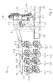
- Fig. 2 shows a drive system 30 for the shedding mechanism 29 comprising sixteen drive motors in a front view.
- Each drive motor is assigned to one drive mechanism 2 and one heald frame 1.
- the drive motor, the associated drive mechanism 2 and the associated heald frame 1 form a subsystem.
- the reference numbers related to elements 2, 3, 4, 5, 6, 8, 9, 10, 11, 13, 14, 15, 16, 17, 18, 19, 20, 31 of the sixteen subsystems are provided with the extension ".1" to ".16".
- a drive motor 31.1 to 31.16 (only 31.1 to 31.8 visible in Fig. 2 ) is assigned to each of the drive mechanisms 2.1 to 2.16 (only 2.1 to 2.8 visible in Fig. 2 ).
- Each crank 3.1 to 3.16 is driven by an individual drive motor 31.1 to 31.16.
- the crank axes 4.1 to 4.16 of the drive mechanisms 2.1 to 2.16 are arranged in parallel, but at a distance from each other in the axial direction and/or perpendicular to the axial direction.
- the shedding mechanism 29 can comprise at least one pair of almost identical drive mechanisms 2 having axially aligned crank axes 4.1 to 4.16, wherein the associated drive motors 31.1 to 31.16 are arranged at opposite sides of a housing 32. In other embodiments, all crank axes 4.1 to 4.16 are at a distance from each other.
- All swivel levers 6.1 to 6.16 are swivelable about a common swivel axis 7. Due to different positions of the crank axes 4.1 to 4.16 a distance between the first hinged joint 16.1 to 16.16 on the crank 3.1 to 3.16 and the second hinged joint 17.1 to 17.16 differs for the different subsystems, and, hence, the length of the coupling rods 5.1 to 5.16 differs for different drive mechanisms 2.1 to 2.16. Therefore, the first swivel levers 6.1 to 6.16 are individually designed for each drive mechanism 2.1 to 2.16, wherein first swivel levers 6.1 to 6.16 of subsystems having axially aligned crank axes 4.1 to 4.16 may have an identical design.
- a first swivel lever 6.1 of the first swivel levers 6 differs from a second swivel lever 6.2 of the first swivel levers 6 in an angle between the respective first arm 8.1, 8.2 and the respective second arm 9.1, 9.2.
- Fig. 3 shows a detail III of a shedding mechanism of Fig. 2 , wherein first swivel levers are arranged in a setting position.
- the setting positions are chosen such that when all first swivel levers 6.1 to 6.16 are arranged in the setting positions the first arms 8.1 to 8.16 of all first swivel levers 6.1 to 6.16 - or as shown of the first swivel levers 6.2 to 6.16 with the exception of the foremost swivel lever 6.1 of the first swivel levers 6 - are at least essentially aligned in a direction parallel to the swivel axis 7.
- the setting positions are chosen such that when all first swivel levers 6.1 to 6.16 are in the setting positions the first arms 8.1 to 8.16 of the first swivel levers 6.1 to 6.16 are arranged funnel shaped, wherein all first swivel levers 6.1 to 6.16 are arranged at least partly at a distance from a virtual access plane opposite to the mounting elements 18.1 to 18.16, wherein in an access direction 33 indicated by an arrow each first swivel lever 6.1 to 6.16 is further away or at the same distance from the virtual access plane than any subsequent first swivel lever 6.2 to 6.16.
- access direction shielding of first arms 8.2 to 8.16 of subsequent first swivel levers 6.2 to 6.16 is avoided.
- the setting positions in preferred embodiments are chosen close to the upper positions of the first swivel levers 6.1 to 6.16, wherein the first swivel levers 6.1 to 6.16 are rotated away from the fixation element 15.
- the setting positions preferably are distinct from the upper positions to allow a relative movement between the blocking device 40 and the shedding mechanism 29 as will be explained below.
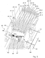
- Figs. 4 and 5 show in a perspective view from above of a part of a shedding unit comprising a blocking device 40 and a shedding mechanism 29, which part is arranged opposite to the drive system 30 shown in Fig. 2 on the weaving machine. More particular, Figs. 4 and 5 show the second swivels levers 11.1 to 11.16 of the shedding mechanism 29 and the blocking device 40, which in the embodiment shown is adapted to interact with the second swivel levers 11.1 to 11.16, more particular with the first arms 19.1 to 19.16 of the second swivel levers 11.1 to 11.16.
- the blocking device 40 comprises a number of blocking elements 41.1 to 41.16.
- the blocking elements 41.1 to 41.16 are provided on a conjoint blocking component 42.
- the blocking elements 41.1 to 41.16 are conjointly moveable between a weaving place shown in Fig. 5 and a blocking place shown in Fig. 4 .
- each blocking element 41.1 to 41.16 is arranged behind one second swivel lever 11.1 to 11.16 and prevents a further rotation of said second swivel lever 11.1 to 11.16 in at least one direction and, thus, a further rotation of the first swivel lever 6.1 to 6.16 beyond their setting positions shown in Fig. 3 towards their lower positions.
- the blocking elements 41.1 to 41.16 arranged in the blocking places shown in Fig. 4 prevent a further clockwise rotation of the second swivel levers 11.1 to 11.16.
- the blocking elements 41.1 to 41.16 are arranged at a distance from the shedding mechanism 29 and do not interfere with the movement of any moveable part of the shedding mechanism 29.
- the blocking places of the first blocking elements 41.1 to 41.16 are not identical. In a plane perpendicular to the common swivel axis 7 of the first swivel levers 6 (see Fig. 1 ) and, thus, perpendicular to the common swivel axis 12 of the second swivel levers 11.1 to 11.16 the blocking places of the first blocking elements 41.1 to 41.16 at least partly differ to block a movement of the second swivel levers 11.1 to 11.16 as shown in Fig. 4 , wherein the first arms 19.1 to 19.16 and/or the second arms 20.1 to 20.16 of the second swivel levers 11.1 to 11.16 are not levelled.
- the blocking component 42 is a plate, wherein a narrow front side 43 of the plate is provided with a number of ribs and recesses.
- the front side 43 provided with a number of recesses and ribs is also referred to as a tooth profile front side.
- the tooth profile front side is adapted to the design of the shedding mechanism 29, more particular to the design of the first swivel levers 6.1 to 6.16 and the orientation of the shedding mechanism 29 when the first swivel levers 6.1 to 6.16 are in the setting positions.
- the ribs and recesses may have at least partly the same height or depth. In other embodiments, an irregular pattern of the tooth profile front side is provided with ribs and recesses that all differ in height or depth.
- the plate is moved into a movement path of the second swivel levers 11.1 to 11.16 and the narrow front side is adapted to interact with the second swivel levers 11.1 to 11.16 to prevent a clockwise movement and, thus, a movement of the connected first swivel levers 6.1 to 6.16 of the drive mechanisms 2 out of their setting positions towards their lower positions.
- the blocking component 42 in the form of a plate is mounted by means of two supports 44 arranged on the frame 22 swivelable about a blocking device swivel axis 45 between the weaving place shown in Fig. 5 and the blocking place shown in Fig. 4 , wherein the blocking device swivel axis 45 is in parallel to the first swivel axis 7 and the second swivel axis 12.
- the blocking component 42 in the form of a plate is forced into the weaving place by means of a return element 46, in particular a spring, arranged between the tooth profile front side and the blocking device swivel axis 45.
- the blocking component 42 is moved by means of an actuator device 47, which is also arranged between the tooth profile front side and the blocking device swivel axis 45 to move the blocking component 42 against the return force of the return element 46 into the blocking place shown in Fig. 4 .
- the actuator device 47 is controlled by a control device (not shown) via a wire 48.
- all drive mechanisms 2 are driven to move the first swivel levers 6.1 to 6.16 into or close to the upper positions.
- the blocking device 40 is driven to move the blocking elements 41.1 to 41.16 into the blocking places.
- the drive mechanisms 2 are driven to move the first swivel levers 6.1 to 6.16 towards the lower positions into the setting positions, wherein a movement beyond the setting positons is blocked by means of the blocking elements 41.1 to 41.16.
- Figs. 6 and 7 show in a perspective view a blocking device 40 with the blocking elements arranged in a weaving place and a blocking place, respectively.
- the blocking device 40 shown in Figs. 6 and 7 is similar to the blocking device 40 shown in Figs. 4 and 5 , and also comprises a number of blocking elements 41.1 to 41.16, which are provided on a conjoint blocking component 42 in the form of a plate.
- the blocking elements 41.1 to 41.16 are conjointly moveable between a weaving place shown in Fig. 6 and a blocking place shown in Fig. 7 . More particular, in the embodiment shown in Figs. 6 and 7 , the blocking component 42 in the form of a plate is mounted swivelable between the weaving place shown in Fig.
- the actuator device 47 and the return element 46 are both arranged on the side of the plate provided with the tooth profile front side with respect to the blocking device swivel axis 45.
- the blocking component 42 in the form of a plate is forced into the weaving place by means of a return element and moved by means of the actuator device against the return force of the return element into the blocking place shown in Fig. 7 .
- the actuator device and the return element engage with the blocking component 42 at opposite sides with respect to the blocking device swivel axis 45.
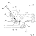
- Fig. 8 shows the blocking device 40 of Figs. 6 and 7 together with second swivel levers 11.1 to 11.16 in a side view.
- all drive mechanisms 2 are driven to move the first swivel levers 6 into or close to the upper positions.
- the blocking device 40 is driven to move the blocking elements 41 into the blocking places as shown in Figs. 7 and 8 .
- the drive mechanisms 2 are driven to move the first swivel levers 6 towards the lower positions into the setting positions, wherein the second swivel levers 11 abut against the blocking elements of the blocking component and a movement beyond the setting positons is blocked by means of the blocking elements 41.
- the blocking device 40 forms an over-center mechanism together with the shedding mechanism 29, so that forces applied by the return element 46 indicated by an arrow 51 for swiveling the blocking component 42 counterclockwise and, thus, move the blocking elements 41 out of the blocking place towards the weaving place, are countered or exceeded by the forces indicated by an arrow 52 acting on the blocking elements 41 in contact with the shedding mechanism 29 due to gravitational forces acting on the shedding mechanism 29.
- the actuator device 47 can be deactivated after the first swivel levers 6 of the shedding mechanism 29 have been moved into the setting positions.
- the shedding mechanism 29 is first driven to bring all first swivel levers 6 towards their upper positions.
- the blocking component 42 is moved by means of the return force of the return element 46 into the weaving place.
- at least one sensor device 53, 54 is provided for detecting in the weaving place the presence or the absence of the blocking elements. In this case, a normal weaving operation can be prevented until all blocking elements are in the weaving place.
- the sensor device 53 is provided at the actuator device 47 for detecting the presence in the blocking place
- the sensor device 54 is provided at the actuator device 47 for detecting the presence in the weaving place.
- Figs. 9 and 10 show a second embodiment of a blocking device 40 having blocking elements 41.1 to 41.16 (only partly visible), wherein the blocking elements 41.1 to 41.16 are adapted to be arranged in a blocking place and a weaving place, respectively.
- the blocking elements 41.1 to 41.16 of the blocking device 40 shown in Figs. 9 and 10 are also provided on a conjoint blocking component 42 in the form of a plate.
- the blocking component 42 is not mounted moveable, more particular not swivelable, on a frame 22 of the weaving machine.
- the blocking component 42 is detachably mounted on the frame 22, wherein at least two mounting positions for arranging the blocking elements 41.1 to 41.16 in the blocking place and in the weaving place are provided.
- the blocking elements 41.1 to 41.16 are arranged in their blocking places and block a clockwise swivel-movement of the second swivel levers 11.1 to 11.16.
- a sensor device 49 is provided for detecting the presence or the absence of the blocking component 42.
- the blocking elements 41.1 to 41.16 are arranged in their weaving places and do not prevent a swivel-movement of the second swivel levers 11.1 to 11.16 and/or a movement of any other moveable component of the shedding mechanism 29.
- the blocking device 40 is adapted to hold the shedding mechanism 29 in a setting position, wherein in the setting position at least one heald frame 1 is not levelled with the remaining heald frames 1.
- the shedding unit further comprises a levelling bar wherein all second arms 9.1 to 9.16 of the first swivel levers 6.1 to 6.16 are levelled by means of a levelling bar arranged on a frame 22 blocking, for example, the transmission rods 13.1 to 13.16. Due to the different designs of the first swivel levers 6.1 to 6.16, the first arms 8.1 to 8.2 are not aligned in one row when the second arms 9.1 to 9.2 are levelled.
- Figs. 11 and 12 show a levelling device 60 provided with a moveably mounted levelling device blocking element 62 for levelling all heald frames 1 of a shedding mechanism 29 as shown in Fig. 1 , wherein the levelling device blocking element 62 is arranged in a levelling device weaving place and levelling device blocking place, respectively.
- the levelling device blocking element 62 is a moveably, more particular rotatably or swivelably mounted plate.
- the levelling device 60 is also arranged opposite to the drive system 30 (see Fig. 2 ) on the weaving machine, wherein the levelling device 60 is arranged to interact with the second arms 20.1 to 20.16 of the second swivel levers 11.1 to 11.16.
- the levelling device blocking element 62 in the form of a plate is arranged swivelable about a swivel axis 65.
- the levelling device 60 further comprises an actuator device 67 and a spring 66, wherein the levelling device blocking element 62 is swivelable by means of the actuator device 67 against the force of the spring 66 about the swivel axis 65 into the levelling device blocking place shown in Fig. 12 .
- a sensor device 63 can be provided to check if the levelling places are reached.
Landscapes
- Engineering & Computer Science (AREA)
- Textile Engineering (AREA)
- Looms (AREA)
Description
- The invention relates to a blocking device for a shedding mechanism of a weaving machine adapted to block a movement of heald frames of the shedding mechanism during set-up. The invention further relates to a shedding unit with a blocking device and a shedding mechanism and to a weaving machine comprising a shedding unit.
-
JP 3988273 B2 -
JP 4610137 B2 - It is an object of the invention to provide a shedding unit for a weaving machine, the shedding unit comprising a blocking device and a shedding mechanism, the shedding mechanism comprising a drive mechanism, wherein a coupling rod is connected to a first arm of a first swivel lever adjustable in location by means of a mounting element, the blocking device allowing for easy access to the coupling elements during set-up, wherein heald frames of the shedding mechanism are securely held in place without a drive motor assigned to the shedding mechanism is activated.
- According to a first aspect a shedding unit for a weaving machine is provided, the shedding unit comprising a blocking device and a shedding mechanism, the shedding mechanism comprising a number of heald frames and a number of drive mechanisms, wherein each drive mechanism is assigned to one heald frame and comprises at least a coupling rod and a first swivel lever having a first arm and a second arm, wherein the coupling rod is connected to the first arm of the first swivel lever adjustable in location by means of a mounting element and wherein the heald frame, to which the drive mechanism is assigned, is coupled to the second arm of the first swivel lever, wherein all first swivel levers are swivelable to-and-fro about a common swivel axis between an upper position and a lower position, wherein each first swivel lever is swivelable into a setting position for setting the location of the associated coupling rod with respect to the first arm of the first swivel lever, and the blocking device comprises a number of blocking elements, each blocking element is assigned to one drive mechanism, wherein each blocking element is moveable between a weaving place and a blocking place, wherein each blocking element in its blocking place interacts with the assigned drive mechanism to prevent a movement of the first swivel lever of said drive mechanism beyond the setting position towards the lower position, and wherein in a plane perpendicular to the common swivel axis the blocking place of at least one first blocking element of the number of blocking elements differs from the blocking place of at least one second blocking element of the number of blocking elements.
- By means of the blocking device, a downward movement of the heald frames is prevented, whereas gravitational forces act against an upward movement. For an easy access to the coupling elements provided on the first arms of the first swivel levers, it is desirable to bring all first arms into a suitable position. In particular in case the shedding mechanism comprises first swivel levers that differ in design, for example in the angle between the first arm and the second arm, when levelling all second arms as known from the prior art, a first arm may shield or hide further first arms arranged downstream in an access direction, and thereby prevent or hinder an access to these further first arms arranged downstream in the access direction.
- To ensure that all first arms are in a suitable setting position for a set-up, a blocking device with blocking elements is conceivable, wherein the blocking elements in the blocking place interact with the first arms, and wherein all blocking elements in the blocking place are at least essentially aligned in a direction parallel to the swivel axis or are arranged such that in an access direction each first arm of the first swivel levers is further away or at the same distance from a virtual access plane opposite the mounting elements than any subsequent first arm.
- Due to space limitations, providing blocking elements interacting with the first arms is not always feasible. Therefore, in accordance with the invention blocking elements having different blocking places in a plane perpendicular to the swivel axis are provided, wherein in preferred embodiments the blocking elements are adapted to interact with the second arms of the first swivel levers and/or with further elements of the shedding mechanism, for example the heald frames.
- In an embodiment, each drive mechanism further comprises a second swivel lever connected to the first swivel lever by means of a transmission rod, wherein the blocking elements are adapted to interact with the second swivel levers, in particular with the first arms of the second swivel levers to which the transmission rods are connected, to prevent a movement of the first swivel levers beyond the setting positions towards the lower positions.
- In preferred embodiments, the blocking elements are provided on a conjoint blocking component, which blocking component is moveable to bring all blocking elements conjointly into their blocking places. In accordance with the invention, blocking elements having different blocking places in a plane perpendicular to the swivel axis are provided. Therefore, the blocking component has a non-linear contact surface and/or a contact surface, which is not in parallel to the swivel axis.
- In preferred embodiments, the blocking component has at least one rib and/or at least one recess for forming the at least one first blocking element and the at least one second blocking element, wherein in a plane perpendicular to the common swivel axis the blocking place of the at least one first blocking element differs from the blocking place of the at least one second blocking element. In an embodiment, the blocking component is a rod, which is arranged in parallel to the swivel axis for bringing the blocking elements into the blocking places, wherein the rod is provided with circumferential grooves or notches for forming blocking elements having different blocking places in a plane perpendicular to the swivel axis.
- In preferred embodiments, the blocking component is a plate, wherein a narrow front side of the plate is provided with at least one rib and/or at least one recess and the narrow front side is adapted to interact with the drive mechanisms to prevent a movement of the first swivel levers of the drive mechanisms beyond their setting positions towards their lower positions. In particular, in an embodiment the plate has a tooth profile front side, wherein adjacent teeth or ribs and recesses between the teeth or ribs function as blocking elements. A respective plate can be manufactured with high precision at low manufacturing costs.
- In an embodiment, each blocking element or the blocking component is manually moveable into the blocking place. For this purpose, in an embodiment a handle lever is provided, wherein by means of the handle lever the blocking elements are moved or the blocking component is moved into the blocking place against the force of a return element. In preferred embodiments, the blocking component is moveable by means of an actuator device to bring all blocking elements conjointly into and/or out of their blocking places, wherein in particular the blocking component is moveable by means of the actuator device against the force of a return element to bring all blocking elements conjointly into their blocking places. Regardless of the operating device, this means manual device or actuator, in preferred embodiments the blocking elements form an over-center mechanism with the shedding mechanism, so that forces applied by the return element are countered or exceeded by the forces acting on the blocking elements in contact with the shedding mechanism due to gravitational forces acting on the shedding mechanism and the manual force acting on the handle lever or an activation of the actuator for applying force against the return element is no longer required after the shedding mechanism abuts against the blocking elements.
- For this purpose as well as for a simple design, in preferred embodiments, the blocking component is swivelable about a blocking component swivel axis to bring all blocking elements conjointly into their blocking places.
- As mentioned above, in preferred embodiments, drive motors driving the weaving machine and/or the shedding mechanism preferably are deactivated during set-up for preventing an unintended driving of the shedding mechanism or of the weaving machine. In order to always allow a secure access to the coupling elements during set-up, in preferred embodiments a sensor device is provided in the weaving place and/or in the blocking place for detecting the presence or the absence of blocking elements, wherein driving of the drive mechanisms is prevented until all blocking elements are in their weaving places.
- In one embodiment, the first blocking element and the second blocking element are assigned to two drive mechanisms of the number of drive mechanisms having first swivel levers that differ in an angle between the first arm and the second arm.
- The blocking device is adapted to hold the shedding mechanism in a setting position, wherein in the setting position at least one heald frame is not levelled with the remaining heald frames. In an embodiment, the shedding unit in addition is provided with a levelling device for holding all heald frames and/or all drive mechanisms in a levelling position such that all heald frames are levelled. Preferably, the levelling device comprises a levelling device blocking element, which levelling device blocking element is moveably mounted between a levelling device weaving place and a levelling device blocking place, wherein in the levelling device blocking place the levelling device blocking element interacts with the drive mechanisms to block a movement of all first swivel levers out of the levelling position towards the lower position.
- In preferred embodiments, the first swivel levers are moveable, from a position closer to the upper position than the setting position towards the lower position, into the setting position after the blocking elements are moved into their blocking places. In preferred embodiments, the shedding unit can be controlled to move all first swivel levers into their upper positions, to then bring the blocking elements into the blocking places and, finally, to move the first swivel levers towards the lower position into the setting position, in which a further movement of the shedding mechanism is blocked by the blocking elements. As mentioned above, a movement of the blocking elements in preferred embodiments is caused by an actuator device. Preferably, after the shedding mechanism abuts the blocking elements, the blocking elements are held in the blocking place due to the forces applied by the shedding mechanism and the actuator device can be deactivated.
- In an embodiment, the blocking elements interact with the first swivel levers to prevent a movement of the first swivel levers beyond the setting positions towards the lower positions. Depending on space specifications, the blocking elements in embodiments of the invention can interact with the first arm, the second arm, and, if provided any one further arm of the first swivel levers and/or with the heald frames.
- In other embodiments, each drive mechanism further comprises a second swivel lever connected to the first swivel lever by means of a transmission rod, wherein the blocking elements interact with the second swivel levers to prevent a movement of the first swivel levers beyond the setting positions towards the lower positions. The arrangement of the blocking elements at the opposite side of a weaving machine with respect to the first swivel levers is particularly suitable for efficiently using available space specifications of known weaving machines.
- As mentioned above, the blocking places are chosen such that the mounting elements are easy to access, when all first swivel levers are arranged in the setting positions. For this purpose, in an embodiment when all first swivel levers are arranged in the setting positions the first arms of all first swivel levers are at least essentially aligned in a direction parallel to the common swivel axis. In other embodiments, when all first swivel levers are arranged in the setting positions the first arms of the first swivel levers are at least partly at a distance from a virtual access plane opposite to the mounting elements, wherein in an access direction each first swivel lever is further away or at the same distance from the virtual access plane than any one subsequent first swivel lever.
- In an embodiment, at least one drive motor which is distinct from the main motor of the weaving machine is provided for driving the shedding mechanism. In preferred embodiments the drive mechanisms are assigned to at least two different drive motors arranged at a distance in position with respect to the swivel axis. More particular, in an embodiment a number of drive motors is provided, wherein each drive mechanism is assigned to an associated drive motor, wherein the drive motors are arranged at least partly in different positions with respect to the swivel axis.
- According to a second aspect, a weaving machine comprising a shedding unit as described above is provided. According to a third aspect, a use of a blocking device for a shedding mechanism of a weaving machine is provided.
- In the following, an embodiment of the invention will be described in detail with reference to the drawings. Throughout the drawings, the same elements will be denoted by the same reference numerals.
-
Fig. 1 shows a heald frame and a drive mechanism of a shedding mechanism. -
Fig. 2 shows a drive system for the shedding mechanism ofFig. 1 . -
Fig. 3 shows a detail III of the shedding mechanism ofFig. 2 , wherein first swivel levers are arranged in a setting position. -
Fig. 4 shows a blocking device for the shedding mechanism ofFig. 1 , wherein the blocking elements are arranged in a blocking place. -
Fig. 5 shows the blocking device ofFig. 4 , wherein the blocking elements are arranged in a weaving place. -
Fig. 6 shows the blocking device for the shedding mechanism ofFig. 1 , wherein the blocking elements are arranged in a weaving place. -
Fig. 7 shows the blocking device ofFig. 6 , wherein the blocking elements are arranged in a blocking place. -
Fig. 8 shows the blocking device ofFig. 6 together with second swivel levers of the shedding mechanism, wherein the blocking elements are arranged in a blocking place. -
Fig. 9 shows a second embodiment of a blocking device for the shedding mechanism ofFig. 1 , wherein the blocking elements are arranged in a blocking place. -
Fig. 10 shows the blocking device ofFig. 9 , wherein the blocking elements are arranged in a weaving place. -
Fig. 11 shows a levelling device for the shedding mechanism ofFig. 1 , wherein a levelling device blocking element is arranged in a levelling device weaving place. -
Fig. 12 shows the levelling device ofFig. 11 , wherein the levelling device blocking element is arranged in a levelling device blocking place. -
Fig. 1 shows a heald frame 1 and adrive mechanism 2 of ashedding mechanism 29. Theshedding mechanism 29 comprises a number of heald frames 1 and an equal number ofdrive mechanisms 2, wherein onedrive mechanism 2 is assigned to one heald frame 1. Thedrive mechanisms 2 are driven by adrive system 30 shown inFig. 2 . - The
drive mechanism 2 for driving the heald frame 1 shown inFig. 1 comprises a crank 3 rotating about a crank axis 4, acoupling rod 5, and afirst swivel lever 6. Thefirst swivel lever 6 is swivelable to-and-fro about afirst swivel axis 7, also namedcommon swivel axis 7, between an upper position and a lower position. Thefirst swivel lever 6 has a first arm 8, asecond arm 9 and athird arm 10, wherein thesecond arm 9 is arranged between the first arm 8 and thethird arm 10 at an angle of approximately 90° to the first arm 8 and thethird arm 10. Thedrive mechanism 2 further comprises asecond swivel lever 11 that is swivelable to-and-fro about asecond swivel axis 12 between an upper position and a lower position. Thesecond swivel lever 11 has afirst arm 19 and asecond arm 20, arranged at an angle of approximately 90°. Thefirst arm 19 is connected to thethird arm 10 of thefirst swivel lever 6 by means of atransmission rod 13 and driven by thefirst swivel lever 6 to move conjointly with thefirst swivel lever 6. - The heald frame 1 is attached to the
second arm 9 of thefirst swivel lever 6 by means of an attaching arrangement comprising a liftingrod 14 and afixation element 15 that is guided in the weaving machine. The heald frame 1 is further attached via a liftingrod 14 and afixation element 15 to thesecond arm 20 of thesecond swivel lever 11. - The
coupling rod 5 of thedrive mechanism 2 is connected to the crank 3 by a first hinged joint 16, which first hinged joint 16 is eccentric to the crank axis 4. Further, thecoupling rod 5 is connected to the first arm 8 of thefirst swivel lever 6 by a second hinged joint 17. - A mounting
element 18 is provided and thecoupling rod 5 is mounted to the first arm 8 adjustable in location by means of the mountingelement 18. In the embodiment shown, the mountingelement 18 is slidably mounted to the first arm 8 of thefirst swivel lever 6 and fixable in a mounting position to the first arm 8. Thecoupling rod 5 is pivotally mounted to the mountingelement 18 by the second hinged joint 17. For setting a stroke of the heald frame 1, a location of the second hinged joint 17 can be adjusted with respect to the first arm 8 of thefirst swivel lever 6 by moving the mountingelement 18 along the first arm 8. The closer the mountingelement 18 and, hence, the location of the second hinged joint 17 is moved towards thefirst swivel axis 7, the larger the stroke of the heald frame 1. The farther the mountingelement 18 and, hence, the location of the second hinged joint 17 is moved away from thefirst swivel axis 7, the smaller the stroke of the heald frame 1. - In order to avoid a movement of the heald frame 1 and/or the
drive mechanism 2 during the set-up of theshedding mechanism 29, this means when adjusting the stroke length, a blockingdevice 40 is provided, which inFig. 1 is schematically shown as a rectangle, which blockingdevice 40 in preferred embodiments for an optimum use of installation space is arranged to interact with thefirst arm 19 of thesecond swivel lever 11. In alternative, as indicated by rectangles in broken lines, the blockingdevice 40 could be arranged to interact with thethird arm 10 of thefirst swivel lever 6 or with thesecond arm 20 of thesecond swivel lever 11. Due to space limitations, in the embodiment shown an arrangement of a blocking device interacting with the first arm 8 or thesecond arm 9 of thefirst swivel lever 6 is not technically rational with theshedding mechanism 29 shown inFig. 1 . However, such an arrangement may be possible in other shedding mechanisms. -
Fig. 2 shows adrive system 30 for theshedding mechanism 29 comprising sixteen drive motors in a front view. Each drive motor is assigned to onedrive mechanism 2 and one heald frame 1. The drive motor, the associateddrive mechanism 2 and the associated heald frame 1 form a subsystem. Hereafter, the reference numbers related toelements - A drive motor 31.1 to 31.16 (only 31.1 to 31.8 visible in
Fig. 2 ) is assigned to each of the drive mechanisms 2.1 to 2.16 (only 2.1 to 2.8 visible inFig. 2 ). Each crank 3.1 to 3.16 is driven by an individual drive motor 31.1 to 31.16. The crank axes 4.1 to 4.16 of the drive mechanisms 2.1 to 2.16 are arranged in parallel, but at a distance from each other in the axial direction and/or perpendicular to the axial direction. Theshedding mechanism 29 can comprise at least one pair of almostidentical drive mechanisms 2 having axially aligned crank axes 4.1 to 4.16, wherein the associated drive motors 31.1 to 31.16 are arranged at opposite sides of ahousing 32. In other embodiments, all crank axes 4.1 to 4.16 are at a distance from each other. - All swivel levers 6.1 to 6.16 are swivelable about a
common swivel axis 7. Due to different positions of the crank axes 4.1 to 4.16 a distance between the first hinged joint 16.1 to 16.16 on the crank 3.1 to 3.16 and the second hinged joint 17.1 to 17.16 differs for the different subsystems, and, hence, the length of the coupling rods 5.1 to 5.16 differs for different drive mechanisms 2.1 to 2.16. Therefore, the first swivel levers 6.1 to 6.16 are individually designed for each drive mechanism 2.1 to 2.16, wherein first swivel levers 6.1 to 6.16 of subsystems having axially aligned crank axes 4.1 to 4.16 may have an identical design. As shown inFig. 2 , for example a first swivel lever 6.1 of the first swivel levers 6 differs from a second swivel lever 6.2 of the first swivel levers 6 in an angle between the respective first arm 8.1, 8.2 and the respective second arm 9.1, 9.2. - In accordance with the invention, for setting the location of the associated coupling rod 5.1 to 5.16 with respect to the first arm 8.1 to 8.16 of the first swivel lever 6.1 to 6.16 all first swivel levers 6.1 to 6.16 are brought into a setting position.
-
Fig. 3 shows a detail III of a shedding mechanism ofFig. 2 , wherein first swivel levers are arranged in a setting position. - The setting positions are chosen such that when all first swivel levers 6.1 to 6.16 are arranged in the setting positions the first arms 8.1 to 8.16 of all first swivel levers 6.1 to 6.16 - or as shown of the first swivel levers 6.2 to 6.16 with the exception of the foremost swivel lever 6.1 of the first swivel levers 6 - are at least essentially aligned in a direction parallel to the
swivel axis 7. In alternative, the setting positions are chosen such that when all first swivel levers 6.1 to 6.16 are in the setting positions the first arms 8.1 to 8.16 of the first swivel levers 6.1 to 6.16 are arranged funnel shaped, wherein all first swivel levers 6.1 to 6.16 are arranged at least partly at a distance from a virtual access plane opposite to the mounting elements 18.1 to 18.16, wherein in anaccess direction 33 indicated by an arrow each first swivel lever 6.1 to 6.16 is further away or at the same distance from the virtual access plane than any subsequent first swivel lever 6.2 to 6.16. In other words, in access direction shielding of first arms 8.2 to 8.16 of subsequent first swivel levers 6.2 to 6.16 is avoided. - Setting of the location of the coupling rod 5.1 to 5.16 with respect to the associated first arm 8.1 to 8.16 of the first swivel lever 6.1 to 6.16 is carried out for example using a
tool 34 with an adjustable aligningaid 35, which is arranged on an upper end of the first arms 8.1 to 8.16 during the setting. In order to allow for sufficient access space for a user carrying out the set-up, the setting positions in preferred embodiments are chosen close to the upper positions of the first swivel levers 6.1 to 6.16, wherein the first swivel levers 6.1 to 6.16 are rotated away from thefixation element 15. However, the setting positions preferably are distinct from the upper positions to allow a relative movement between the blockingdevice 40 and theshedding mechanism 29 as will be explained below. -
Figs. 4 and5 show in a perspective view from above of a part of a shedding unit comprising a blockingdevice 40 and ashedding mechanism 29, which part is arranged opposite to thedrive system 30 shown inFig. 2 on the weaving machine. More particular,Figs. 4 and5 show the second swivels levers 11.1 to 11.16 of theshedding mechanism 29 and the blockingdevice 40, which in the embodiment shown is adapted to interact with the second swivel levers 11.1 to 11.16, more particular with the first arms 19.1 to 19.16 of the second swivel levers 11.1 to 11.16. - The blocking
device 40 comprises a number of blocking elements 41.1 to 41.16. In the embodiment shown, the blocking elements 41.1 to 41.16 are provided on aconjoint blocking component 42. The blocking elements 41.1 to 41.16 are conjointly moveable between a weaving place shown inFig. 5 and a blocking place shown inFig. 4 . - In the blocking place shown in
Fig. 4 each blocking element 41.1 to 41.16 is arranged behind one second swivel lever 11.1 to 11.16 and prevents a further rotation of said second swivel lever 11.1 to 11.16 in at least one direction and, thus, a further rotation of the first swivel lever 6.1 to 6.16 beyond their setting positions shown inFig. 3 towards their lower positions. In the embodiment shown, the blocking elements 41.1 to 41.16 arranged in the blocking places shown inFig. 4 prevent a further clockwise rotation of the second swivel levers 11.1 to 11.16. In the weaving place, the blocking elements 41.1 to 41.16 are arranged at a distance from theshedding mechanism 29 and do not interfere with the movement of any moveable part of theshedding mechanism 29. - The blocking places of the first blocking elements 41.1 to 41.16 are not identical. In a plane perpendicular to the
common swivel axis 7 of the first swivel levers 6 (seeFig. 1 ) and, thus, perpendicular to thecommon swivel axis 12 of the second swivel levers 11.1 to 11.16 the blocking places of the first blocking elements 41.1 to 41.16 at least partly differ to block a movement of the second swivel levers 11.1 to 11.16 as shown inFig. 4 , wherein the first arms 19.1 to 19.16 and/or the second arms 20.1 to 20.16 of the second swivel levers 11.1 to 11.16 are not levelled. - In the embodiment shown in
Figs. 4 and5 theblocking component 42 is a plate, wherein a narrowfront side 43 of the plate is provided with a number of ribs and recesses. Thefront side 43 provided with a number of recesses and ribs is also referred to as a tooth profile front side. The tooth profile front side is adapted to the design of theshedding mechanism 29, more particular to the design of the first swivel levers 6.1 to 6.16 and the orientation of theshedding mechanism 29 when the first swivel levers 6.1 to 6.16 are in the setting positions. The ribs and recesses may have at least partly the same height or depth. In other embodiments, an irregular pattern of the tooth profile front side is provided with ribs and recesses that all differ in height or depth. - The plate is moved into a movement path of the second swivel levers 11.1 to 11.16 and the narrow front side is adapted to interact with the second swivel levers 11.1 to 11.16 to prevent a clockwise movement and, thus, a movement of the connected first swivel levers 6.1 to 6.16 of the
drive mechanisms 2 out of their setting positions towards their lower positions. - In an embodiment, the blocking
component 42 in the form of a plate is mounted by means of twosupports 44 arranged on theframe 22 swivelable about a blockingdevice swivel axis 45 between the weaving place shown inFig. 5 and the blocking place shown inFig. 4 , wherein the blockingdevice swivel axis 45 is in parallel to thefirst swivel axis 7 and thesecond swivel axis 12. In the embodiment shown inFigs. 4 and5 , the blockingcomponent 42 in the form of a plate is forced into the weaving place by means of areturn element 46, in particular a spring, arranged between the tooth profile front side and the blockingdevice swivel axis 45. The blockingcomponent 42 is moved by means of anactuator device 47, which is also arranged between the tooth profile front side and the blockingdevice swivel axis 45 to move theblocking component 42 against the return force of thereturn element 46 into the blocking place shown inFig. 4 . Theactuator device 47 is controlled by a control device (not shown) via awire 48. - In a preferred use, for a set-up, all drive
mechanisms 2 are driven to move the first swivel levers 6.1 to 6.16 into or close to the upper positions. Next, the blockingdevice 40 is driven to move the blocking elements 41.1 to 41.16 into the blocking places. Finally, thedrive mechanisms 2 are driven to move the first swivel levers 6.1 to 6.16 towards the lower positions into the setting positions, wherein a movement beyond the setting positons is blocked by means of the blocking elements 41.1 to 41.16. -
Figs. 6 and7 show in a perspective view ablocking device 40 with the blocking elements arranged in a weaving place and a blocking place, respectively. The blockingdevice 40 shown inFigs. 6 and7 is similar to the blockingdevice 40 shown inFigs. 4 and5 , and also comprises a number of blocking elements 41.1 to 41.16, which are provided on aconjoint blocking component 42 in the form of a plate. The blocking elements 41.1 to 41.16 are conjointly moveable between a weaving place shown inFig. 6 and a blocking place shown inFig. 7 . More particular, in the embodiment shown inFigs. 6 and7 , the blockingcomponent 42 in the form of a plate is mounted swivelable between the weaving place shown inFig. 6 and the blocking place shown inFig. 7 about a blockingdevice swivel axis 45 arranged between twosupports 44. In the embodiment shown theactuator device 47 and thereturn element 46 are both arranged on the side of the plate provided with the tooth profile front side with respect to the blockingdevice swivel axis 45. In alternative, in an embodiment, the blockingcomponent 42 in the form of a plate is forced into the weaving place by means of a return element and moved by means of the actuator device against the return force of the return element into the blocking place shown inFig. 7 . In an embodiment not shown, the actuator device and the return element engage with the blockingcomponent 42 at opposite sides with respect to the blockingdevice swivel axis 45. -
Fig. 8 shows the blockingdevice 40 ofFigs. 6 and7 together with second swivel levers 11.1 to 11.16 in a side view. As described above, for a set-up preferably all drivemechanisms 2 are driven to move the first swivel levers 6 into or close to the upper positions. Next, the blockingdevice 40 is driven to move the blocking elements 41 into the blocking places as shown inFigs. 7 and8 . Finally, thedrive mechanisms 2 are driven to move the first swivel levers 6 towards the lower positions into the setting positions, wherein the second swivel levers 11 abut against the blocking elements of the blocking component and a movement beyond the setting positons is blocked by means of the blocking elements 41. In the absence of the blockingdevice 40, due to gravitational forces, the second swivel levers 11 can rotate clockwise into their lower positions. As shown inFig. 8 , in the embodiment shown inFigs. 6 to 8 , the blockingdevice 40 forms an over-center mechanism together with theshedding mechanism 29, so that forces applied by thereturn element 46 indicated by anarrow 51 for swiveling the blockingcomponent 42 counterclockwise and, thus, move the blocking elements 41 out of the blocking place towards the weaving place, are countered or exceeded by the forces indicated by anarrow 52 acting on the blocking elements 41 in contact with theshedding mechanism 29 due to gravitational forces acting on theshedding mechanism 29. Hence, theactuator device 47 can be deactivated after the first swivel levers 6 of theshedding mechanism 29 have been moved into the setting positions. For starting a weaving operation, theshedding mechanism 29 is first driven to bring all first swivel levers 6 towards their upper positions. After moving theshedding mechanism 29, the blockingcomponent 42 is moved by means of the return force of thereturn element 46 into the weaving place. In preferred embodiments, at least onesensor device sensor device 53 is provided at theactuator device 47 for detecting the presence in the blocking place, and thesensor device 54 is provided at theactuator device 47 for detecting the presence in the weaving place. -
Figs. 9 and10 show a second embodiment of a blockingdevice 40 having blocking elements 41.1 to 41.16 (only partly visible), wherein the blocking elements 41.1 to 41.16 are adapted to be arranged in a blocking place and a weaving place, respectively. - The blocking elements 41.1 to 41.16 of the blocking
device 40 shown inFigs. 9 and10 are also provided on aconjoint blocking component 42 in the form of a plate. In contrast to the previous embodiment, the blockingcomponent 42 is not mounted moveable, more particular not swivelable, on aframe 22 of the weaving machine. The blockingcomponent 42 is detachably mounted on theframe 22, wherein at least two mounting positions for arranging the blocking elements 41.1 to 41.16 in the blocking place and in the weaving place are provided. - When the blocking
component 42 is mounted in the first mounting position as shown inFig. 9 , the blocking elements 41.1 to 41.16 are arranged in their blocking places and block a clockwise swivel-movement of the second swivel levers 11.1 to 11.16. In the embodiment shown, asensor device 49 is provided for detecting the presence or the absence of the blockingcomponent 42. - When the blocking
component 42 is mounted in the second mounting position as shown inFig. 10 , the blocking elements 41.1 to 41.16 are arranged in their weaving places and do not prevent a swivel-movement of the second swivel levers 11.1 to 11.16 and/or a movement of any other moveable component of theshedding mechanism 29. - As described, the blocking
device 40 is adapted to hold theshedding mechanism 29 in a setting position, wherein in the setting position at least one heald frame 1 is not levelled with the remaining heald frames 1. In an embodiment the shedding unit further comprises a levelling bar wherein all second arms 9.1 to 9.16 of the first swivel levers 6.1 to 6.16 are levelled by means of a levelling bar arranged on aframe 22 blocking, for example, the transmission rods 13.1 to 13.16. Due to the different designs of the first swivel levers 6.1 to 6.16, the first arms 8.1 to 8.2 are not aligned in one row when the second arms 9.1 to 9.2 are levelled. -
Figs. 11 and12 show a levellingdevice 60 provided with a moveably mounted levellingdevice blocking element 62 for levelling all heald frames 1 of ashedding mechanism 29 as shown inFig. 1 , wherein the levellingdevice blocking element 62 is arranged in a levelling device weaving place and levelling device blocking place, respectively. The levellingdevice blocking element 62 is a moveably, more particular rotatably or swivelably mounted plate. - In the embodiment shown, the levelling
device 60 is also arranged opposite to the drive system 30 (seeFig. 2 ) on the weaving machine, wherein the levellingdevice 60 is arranged to interact with the second arms 20.1 to 20.16 of the second swivel levers 11.1 to 11.16. The levellingdevice blocking element 62 in the form of a plate is arranged swivelable about aswivel axis 65. The levellingdevice 60 further comprises anactuator device 67 and aspring 66, wherein the levellingdevice blocking element 62 is swivelable by means of theactuator device 67 against the force of thespring 66 about theswivel axis 65 into the levelling device blocking place shown inFig. 12 . In addition, asensor device 63 can be provided to check if the levelling places are reached. - It is clear to the person skilled in the art that the invention is not limited to the described embodiments and various variations in particular regarding the number of heald frames and associated drive mechanisms and blocking elements are conceivable.
Claims (18)
- Shedding unit for a weaving machine, the shedding unit comprising a blocking device and a shedding mechanism (29), the shedding mechanism (29) comprising a number of heald frames (1) and a number of drive mechanisms (2), wherein each drive mechanism (2) is assigned to one heald frame (1) and comprises at least a coupling rod (5) and a first swivel lever (6) having a first arm (8) and a second arm (9), wherein the coupling rod (5) is connected to the first arm (8) of the first swivel lever (6) adjustable in location by means of a mounting element (18) and wherein the heald frame (1), to which the drive mechanism (2) is assigned, is coupled to the second arm (9) of the first swivel lever (6), wherein all first swivel levers (6) are swivelable to-and-fro about a common swivel axis (7) between an upper position and a lower position, wherein each first swivel lever (6) is swivelable into a setting position for setting the location of the associated coupling rod (5) with respect to the first arm (8) of the first swivel lever (6), characterized in that the blocking device (40) comprises a number of blocking elements (41), each blocking element (41) is assigned to one drive mechanism (2), wherein each blocking element (41) is moveable between a weaving place and a blocking place, wherein each blocking element (41) in its blocking place interacts with the assigned drive mechanism (2) to prevent a movement of the first swivel lever (6) of said drive mechanism (2) beyond the setting position towards the lower position, and wherein in a plane perpendicular to the common swivel axis (7) the blocking place of at least one first blocking element of the number of blocking elements (41) differs from the blocking place of at least one second blocking element of the number of blocking elements (41).
- Shedding unit according to claim 1, characterized in that the blocking elements (41.1 to 41.16) are provided on a conjoint blocking component (42), which blocking component (42) is moveable to bring all blocking elements (41.1 to 41.16) conjointly into their blocking places.
- Shedding unit according to claim 2, characterized in that the blocking component (42) has at least one rib and/or at least one recess for forming the at least one first blocking element and the at least one second blocking element, wherein in a plane perpendicular to the common swivel axis (7) the blocking place of the at least one first blocking element differs from the blocking place of the at least one second blocking element.
- Shedding unit according to claim 3, characterized in that the blocking component (42) is a plate, wherein a narrow front side (43) of the plate is provided with at least one rib and/or at least one recess and the narrow front side (43) is adapted to interact with the drive mechanism (2) to prevent a movement of the first swivel levers (6) of the drive mechanisms (2) beyond their setting positions towards their lower positions.
- Shedding unit according to claim 4, characterized in that the plate has a tooth profile front side (43).
- Shedding unit according to any one of claims 2 to 5, characterized in that the blocking component (42) is moveable by means of an actuator device (47) to bring all blocking elements (41) conjointly into and/or out of their blocking places, wherein in particular the blocking component (42) is moveable by means of the actuator device (47) against the force of a return element (46) to bring all blocking elements (41.1 to 41.16) conjointly into their blocking places.
- Shedding unit according to any one of claims 2 to 6, characterized in that the blocking component (42) is swivelable about a blocking component swivel axis (45) to bring all blocking elements (41) conjointly into their blocking places.
- Shedding unit according to any one of claims 1 to 7, characterized in that a sensor device (49, 53, 54) is provided in the weaving place and/or in the blocking place for detecting the presence or the absence of blocking elements, wherein driving of the drive mechanisms (2) is prevented until all blocking elements (41) are in their weaving places.
- Shedding unit according to any one of claims 1 to 8 characterized in that the first blocking element and the second blocking element are assigned to two drive mechanisms (2) of the number of drive mechanisms having first swivel levers (6) that differ in an angle between the first arm (8) and the second arm (9).
- Shedding unit according to any one of claims 1 to 9, characterized in that the first swivel levers (6) are moveable from a position closer to the upper position than the setting position towards the lower position into a setting position after the blocking elements (41) are moved into their blocking places.
- Shedding unit according to any one of claims 1 to 10, characterized in that the blocking elements (41) interact with the first swivel levers (6) to prevent a movement of the first swivel levers (6) beyond the setting positions towards the lower positions.
- Shedding unit according to any one of claims 1 to 11, characterized in that each drive mechanism (2) further comprises a second swivel lever (11) connected to the first swivel lever (6) by means of a transmission rod (13), wherein the blocking elements (41) interact with the second swivel levers (11) to prevent a movement of the first swivel levers (6) beyond the setting positions towards the lower positions.
- Shedding unit according to claim 12, characterized in that the blocking elements (41) interact with the first arms (19) of the second swivel levers (11) to which the transmission rods (13) are connected to prevent a movement of the first swivel levers (6) beyond the setting positions towards the lower positions.
- Shedding unit according to any one of claims 1 to 13, characterized in that when all first swivel levers (6) are arranged in the setting positions the first arms (8) of all first swivel levers (6) are at least essentially aligned in a direction parallel to the common swivel axis (7).
- Shedding unit according to any one of claims 1 to 13, characterized in that when all first swivel levers (6) are arranged in the setting positions the first arms (8) of the first swivel levers (6) are at least partly at a distance from a virtual access plane opposite to the mounting elements (18), wherein in an access direction (33) each first swivel lever (6) is further away or at the same distance from the virtual access plane than any subsequent first swivel lever (6).
- Shedding unit according to any one of claims 1 to 15, characterized in that the drive mechanisms (2) are assigned to at least two different drive motors (31) arranged at a distance in position with respect to the common swivel axis (7).
- Weaving machine, characterized in that the weaving machine comprises a shedding unit according to any one of claims 1 to 16.
- Use of a blocking device for a shedding mechanism (29) of a weaving machine, the shedding mechanism (29) comprising a number of heald frames (1) and a number of drive mechanisms (2), wherein each drive mechanism (2) is assigned to one heald frame (1) and comprises at least a coupling rod (5) and a first swivel lever (6) having a first arm (8) and a second arm (9), wherein the coupling rod (5) is connected to the first arm (8) of the first swivel lever (6) adjustable in location by means of a mounting element (18) and wherein the heald frame (1), to which the drive mechanism (2) is assigned, is coupled to the second arm (9) of the first swivel lever (6), wherein all first swivel levers (6) are swivelable to-and-fro about a common swivel axis (7) between an upper position and a lower position, wherein each first swivel lever (6) is swivelable into a setting position for setting the location of the associated coupling rod (5) with respect to the first arm (8) of the first swivel lever (6), characterized in that the blocking device (40) comprises a number of blocking elements (41), each blocking element (41) is assigned to one drive mechanism (2), wherein each blocking element (41) is moveable between a weaving place and a blocking place, wherein each blocking element (41) in its blocking place interacts with the assigned drive mechanism (2) to prevent a movement of the first swivel lever (6) of said drive mechanism (2) beyond the setting position towards the lower position, and wherein in a plane perpendicular to the common swivel axis (7) the blocking place of at least one first blocking element of the number of blocking elements (41) differs from the blocking place of at least one second blocking element of the number of blocking elements (41).
Applications Claiming Priority (2)
| Application Number | Priority Date | Filing Date | Title |
|---|---|---|---|
| BE2016/0124A BE1024363B1 (en) | 2016-07-08 | 2016-07-08 | Blocking device and shedding unit for a weaving machine |
| PCT/EP2017/065504 WO2018007168A1 (en) | 2016-07-08 | 2017-06-23 | Blocking device and shedding unit for a weaving machine |
Publications (2)
| Publication Number | Publication Date |
|---|---|
| EP3481977A1 EP3481977A1 (en) | 2019-05-15 |
| EP3481977B1 true EP3481977B1 (en) | 2021-01-27 |
Family
ID=56609601
Family Applications (1)
| Application Number | Title | Priority Date | Filing Date |
|---|---|---|---|
| EP17731589.2A Active EP3481977B1 (en) | 2016-07-08 | 2017-06-23 | Blocking device and shedding unit for a weaving machine |
Country Status (4)
| Country | Link |
|---|---|
| EP (1) | EP3481977B1 (en) |
| CN (1) | CN109563654B (en) |
| BE (1) | BE1024363B1 (en) |
| WO (1) | WO2018007168A1 (en) |
Cited By (1)
| Publication number | Priority date | Publication date | Assignee | Title |
|---|---|---|---|---|
| FR3132108A1 (en) * | 2022-01-27 | 2023-07-28 | Staubli Faverges | Shedding assembly for a weaving loom and its adjustment method |
Families Citing this family (1)
| Publication number | Priority date | Publication date | Assignee | Title |
|---|---|---|---|---|
| EP4269675B1 (en) | 2019-12-03 | 2025-04-16 | Picanol | Driving device for a shedding unit and method for adjusting a shed stroke |
Family Cites Families (5)
| Publication number | Priority date | Publication date | Assignee | Title |
|---|---|---|---|---|
| IT1208534B (en) * | 1985-04-24 | 1989-07-10 | Fimtessile | NEGATIVE DOBBY FOR WEAVING FRAMES. |
| JP3988273B2 (en) * | 1998-09-03 | 2007-10-10 | 株式会社豊田自動織機 | Hull frame height position holding device in loom |
| JP4610137B2 (en) * | 2001-08-31 | 2011-01-12 | 津田駒工業株式会社 | Braking device for electric opening device |
| FR2842538B1 (en) * | 2002-07-16 | 2004-10-29 | Staubli Sa Ets | ROTARY RATIERE FOR WEAVING, AND WEAVING EQUIPMENT PROVIDED WITH SUCH A RAIL |
| BE1019517A3 (en) * | 2010-09-24 | 2012-08-07 | Picanol | GAAP FORMAT FOR A WEAVING MACHINE. |
-
2016
- 2016-07-08 BE BE2016/0124A patent/BE1024363B1/en not_active IP Right Cessation
-
2017
- 2017-06-23 CN CN201780042588.9A patent/CN109563654B/en active Active
- 2017-06-23 EP EP17731589.2A patent/EP3481977B1/en active Active
- 2017-06-23 WO PCT/EP2017/065504 patent/WO2018007168A1/en not_active Ceased
Non-Patent Citations (1)
| Title |
|---|
| None * |
Cited By (3)
| Publication number | Priority date | Publication date | Assignee | Title |
|---|---|---|---|---|
| FR3132108A1 (en) * | 2022-01-27 | 2023-07-28 | Staubli Faverges | Shedding assembly for a weaving loom and its adjustment method |
| EP4219813A1 (en) * | 2022-01-27 | 2023-08-02 | Staubli Faverges | Shedding assembly for a loom and its adjustment method |
| US12091784B2 (en) | 2022-01-27 | 2024-09-17 | Staubli Faverges | Shedding assembly for a loom and its adjustment method |
Also Published As
| Publication number | Publication date |
|---|---|
| EP3481977A1 (en) | 2019-05-15 |
| BE1024363A1 (en) | 2018-01-30 |
| CN109563654A (en) | 2019-04-02 |
| BE1024363B1 (en) | 2018-02-05 |
| WO2018007168A1 (en) | 2018-01-11 |
| CN109563654B (en) | 2020-10-27 |
Similar Documents
| Publication | Publication Date | Title |
|---|---|---|
| CN101278782B (en) | Reclining device for a adjustable chair | |
| EP2711102B1 (en) | Panel bending machine with swiveling blade | |
| WO2018007168A1 (en) | Blocking device and shedding unit for a weaving machine | |
| JP6526680B2 (en) | Device for holding a control console for a machine tool | |
| EP1987967B1 (en) | Sliding tow hook for farming machines | |
| US20150027246A1 (en) | Drive Devices for Movement Units of Machine Tools and Related Machine Tools | |
| CN116497499A (en) | Shed forming assembly for loom and adjustment method thereof | |
| JP2001191381A (en) | Injection molding machine setting display | |
| CN101086102B (en) | Warp knitting machine | |
| EP4269675B1 (en) | Driving device for a shedding unit and method for adjusting a shed stroke | |
| US10543613B2 (en) | Cutting machine for food | |
| JP5036571B2 (en) | Electric discharge machine | |
| CN113022391B (en) | Seat device for construction machine | |
| JP7016188B2 (en) | Screen printing device and screen printing method | |
| KR20140031625A (en) | A bending machine | |
| EP3738715A1 (en) | Device for supporting spring-damper assemblies for machines for assembling/disassembling vehicle suspensions | |
| EP2893067B1 (en) | Apparatus for presenting weft threads | |
| JP7128993B2 (en) | rebar bending device | |
| CN214683682U (en) | Bending angle adjusting mechanism for bending machine | |
| CN118601087A (en) | Tilt structure of the console | |
| EP3478882A1 (en) | Device for clamping weft threads | |
| EP3369508B1 (en) | A cutting machine for cutting profiled elements | |
| EP1155859B1 (en) | "Apparatus for the alternative cleaning of two or more cylinders in a printing press, with a signle cleaning device" | |
| JP2024173514A6 (en) | Operating device for work machine | |
| US20050005978A1 (en) | Manipulator with electromagnetic detent for the driving servo-control of hydraulic mechanisms |
Legal Events
| Date | Code | Title | Description |
|---|---|---|---|
| STAA | Information on the status of an ep patent application or granted ep patent |
Free format text: STATUS: UNKNOWN |
|
| STAA | Information on the status of an ep patent application or granted ep patent |
Free format text: STATUS: THE INTERNATIONAL PUBLICATION HAS BEEN MADE |
|
| PUAI | Public reference made under article 153(3) epc to a published international application that has entered the european phase |
Free format text: ORIGINAL CODE: 0009012 |
|
| STAA | Information on the status of an ep patent application or granted ep patent |
Free format text: STATUS: REQUEST FOR EXAMINATION WAS MADE |
|
| 17P | Request for examination filed |
Effective date: 20190109 |
|
| AK | Designated contracting states |
Kind code of ref document: A1 Designated state(s): AL AT BE BG CH CY CZ DE DK EE ES FI FR GB GR HR HU IE IS IT LI LT LU LV MC MK MT NL NO PL PT RO RS SE SI SK SM TR |
|
| AX | Request for extension of the european patent |
Extension state: BA ME |
|
| DAV | Request for validation of the european patent (deleted) | ||
| DAX | Request for extension of the european patent (deleted) | ||
| GRAP | Despatch of communication of intention to grant a patent |
Free format text: ORIGINAL CODE: EPIDOSNIGR1 |
|
| STAA | Information on the status of an ep patent application or granted ep patent |
Free format text: STATUS: GRANT OF PATENT IS INTENDED |
|
| INTG | Intention to grant announced |
Effective date: 20201005 |
|
| GRAS | Grant fee paid |
Free format text: ORIGINAL CODE: EPIDOSNIGR3 |
|
| GRAA | (expected) grant |
Free format text: ORIGINAL CODE: 0009210 |
|
| STAA | Information on the status of an ep patent application or granted ep patent |
Free format text: STATUS: THE PATENT HAS BEEN GRANTED |
|
| AK | Designated contracting states |
Kind code of ref document: B1 Designated state(s): AL AT BE BG CH CY CZ DE DK EE ES FI FR GB GR HR HU IE IS IT LI LT LU LV MC MK MT NL NO PL PT RO RS SE SI SK SM TR |
|
| REG | Reference to a national code |
Ref country code: GB Ref legal event code: FG4D |
|
| REG | Reference to a national code |
Ref country code: CH Ref legal event code: EP |
|
| REG | Reference to a national code |
Ref country code: AT Ref legal event code: REF Ref document number: 1358429 Country of ref document: AT Kind code of ref document: T Effective date: 20210215 |
|
| REG | Reference to a national code |
Ref country code: IE Ref legal event code: FG4D |
|
| REG | Reference to a national code |
Ref country code: DE Ref legal event code: R096 Ref document number: 602017032066 Country of ref document: DE |
|
| REG | Reference to a national code |
Ref country code: NL Ref legal event code: MP Effective date: 20210127 |
|
| REG | Reference to a national code |
Ref country code: LT Ref legal event code: MG9D |
|
| REG | Reference to a national code |
Ref country code: AT Ref legal event code: MK05 Ref document number: 1358429 Country of ref document: AT Kind code of ref document: T Effective date: 20210127 |
|
| PG25 | Lapsed in a contracting state [announced via postgrant information from national office to epo] |
Ref country code: NO Free format text: LAPSE BECAUSE OF FAILURE TO SUBMIT A TRANSLATION OF THE DESCRIPTION OR TO PAY THE FEE WITHIN THE PRESCRIBED TIME-LIMIT Effective date: 20210427 Ref country code: PT Free format text: LAPSE BECAUSE OF FAILURE TO SUBMIT A TRANSLATION OF THE DESCRIPTION OR TO PAY THE FEE WITHIN THE PRESCRIBED TIME-LIMIT Effective date: 20210527 Ref country code: GR Free format text: LAPSE BECAUSE OF FAILURE TO SUBMIT A TRANSLATION OF THE DESCRIPTION OR TO PAY THE FEE WITHIN THE PRESCRIBED TIME-LIMIT Effective date: 20210428 Ref country code: HR Free format text: LAPSE BECAUSE OF FAILURE TO SUBMIT A TRANSLATION OF THE DESCRIPTION OR TO PAY THE FEE WITHIN THE PRESCRIBED TIME-LIMIT Effective date: 20210127 Ref country code: FI Free format text: LAPSE BECAUSE OF FAILURE TO SUBMIT A TRANSLATION OF THE DESCRIPTION OR TO PAY THE FEE WITHIN THE PRESCRIBED TIME-LIMIT Effective date: 20210127 Ref country code: BG Free format text: LAPSE BECAUSE OF FAILURE TO SUBMIT A TRANSLATION OF THE DESCRIPTION OR TO PAY THE FEE WITHIN THE PRESCRIBED TIME-LIMIT Effective date: 20210427 Ref country code: LT Free format text: LAPSE BECAUSE OF FAILURE TO SUBMIT A TRANSLATION OF THE DESCRIPTION OR TO PAY THE FEE WITHIN THE PRESCRIBED TIME-LIMIT Effective date: 20210127 |
|
| PG25 | Lapsed in a contracting state [announced via postgrant information from national office to epo] |
Ref country code: AT Free format text: LAPSE BECAUSE OF FAILURE TO SUBMIT A TRANSLATION OF THE DESCRIPTION OR TO PAY THE FEE WITHIN THE PRESCRIBED TIME-LIMIT Effective date: 20210127 Ref country code: PL Free format text: LAPSE BECAUSE OF FAILURE TO SUBMIT A TRANSLATION OF THE DESCRIPTION OR TO PAY THE FEE WITHIN THE PRESCRIBED TIME-LIMIT Effective date: 20210127 Ref country code: RS Free format text: LAPSE BECAUSE OF FAILURE TO SUBMIT A TRANSLATION OF THE DESCRIPTION OR TO PAY THE FEE WITHIN THE PRESCRIBED TIME-LIMIT Effective date: 20210127 Ref country code: LV Free format text: LAPSE BECAUSE OF FAILURE TO SUBMIT A TRANSLATION OF THE DESCRIPTION OR TO PAY THE FEE WITHIN THE PRESCRIBED TIME-LIMIT Effective date: 20210127 Ref country code: SE Free format text: LAPSE BECAUSE OF FAILURE TO SUBMIT A TRANSLATION OF THE DESCRIPTION OR TO PAY THE FEE WITHIN THE PRESCRIBED TIME-LIMIT Effective date: 20210127 |
|
| PG25 | Lapsed in a contracting state [announced via postgrant information from national office to epo] |
Ref country code: IS Free format text: LAPSE BECAUSE OF FAILURE TO SUBMIT A TRANSLATION OF THE DESCRIPTION OR TO PAY THE FEE WITHIN THE PRESCRIBED TIME-LIMIT Effective date: 20210527 |
|
| REG | Reference to a national code |
Ref country code: DE Ref legal event code: R097 Ref document number: 602017032066 Country of ref document: DE |
|
| PG25 | Lapsed in a contracting state [announced via postgrant information from national office to epo] |
Ref country code: SM Free format text: LAPSE BECAUSE OF FAILURE TO SUBMIT A TRANSLATION OF THE DESCRIPTION OR TO PAY THE FEE WITHIN THE PRESCRIBED TIME-LIMIT Effective date: 20210127 Ref country code: EE Free format text: LAPSE BECAUSE OF FAILURE TO SUBMIT A TRANSLATION OF THE DESCRIPTION OR TO PAY THE FEE WITHIN THE PRESCRIBED TIME-LIMIT Effective date: 20210127 Ref country code: CZ Free format text: LAPSE BECAUSE OF FAILURE TO SUBMIT A TRANSLATION OF THE DESCRIPTION OR TO PAY THE FEE WITHIN THE PRESCRIBED TIME-LIMIT Effective date: 20210127 |
|
| PG25 | Lapsed in a contracting state [announced via postgrant information from national office to epo] |
Ref country code: SK Free format text: LAPSE BECAUSE OF FAILURE TO SUBMIT A TRANSLATION OF THE DESCRIPTION OR TO PAY THE FEE WITHIN THE PRESCRIBED TIME-LIMIT Effective date: 20210127 Ref country code: DK Free format text: LAPSE BECAUSE OF FAILURE TO SUBMIT A TRANSLATION OF THE DESCRIPTION OR TO PAY THE FEE WITHIN THE PRESCRIBED TIME-LIMIT Effective date: 20210127 Ref country code: RO Free format text: LAPSE BECAUSE OF FAILURE TO SUBMIT A TRANSLATION OF THE DESCRIPTION OR TO PAY THE FEE WITHIN THE PRESCRIBED TIME-LIMIT Effective date: 20210127 |
|
| PLBE | No opposition filed within time limit |
Free format text: ORIGINAL CODE: 0009261 |
|
| STAA | Information on the status of an ep patent application or granted ep patent |
Free format text: STATUS: NO OPPOSITION FILED WITHIN TIME LIMIT |
|
| 26N | No opposition filed |
Effective date: 20211028 |
|
| PG25 | Lapsed in a contracting state [announced via postgrant information from national office to epo] |
Ref country code: ES Free format text: LAPSE BECAUSE OF FAILURE TO SUBMIT A TRANSLATION OF THE DESCRIPTION OR TO PAY THE FEE WITHIN THE PRESCRIBED TIME-LIMIT Effective date: 20210127 Ref country code: MC Free format text: LAPSE BECAUSE OF FAILURE TO SUBMIT A TRANSLATION OF THE DESCRIPTION OR TO PAY THE FEE WITHIN THE PRESCRIBED TIME-LIMIT Effective date: 20210127 Ref country code: AL Free format text: LAPSE BECAUSE OF FAILURE TO SUBMIT A TRANSLATION OF THE DESCRIPTION OR TO PAY THE FEE WITHIN THE PRESCRIBED TIME-LIMIT Effective date: 20210127 |
|
| REG | Reference to a national code |
Ref country code: CH Ref legal event code: PL |
|
| GBPC | Gb: european patent ceased through non-payment of renewal fee |
Effective date: 20210623 |
|
| PG25 | Lapsed in a contracting state [announced via postgrant information from national office to epo] |
Ref country code: SI Free format text: LAPSE BECAUSE OF FAILURE TO SUBMIT A TRANSLATION OF THE DESCRIPTION OR TO PAY THE FEE WITHIN THE PRESCRIBED TIME-LIMIT Effective date: 20210127 |
|
| PG25 | Lapsed in a contracting state [announced via postgrant information from national office to epo] |
Ref country code: LU Free format text: LAPSE BECAUSE OF NON-PAYMENT OF DUE FEES Effective date: 20210623 |
|
| PG25 | Lapsed in a contracting state [announced via postgrant information from national office to epo] |
Ref country code: LI Free format text: LAPSE BECAUSE OF NON-PAYMENT OF DUE FEES Effective date: 20210630 Ref country code: IE Free format text: LAPSE BECAUSE OF NON-PAYMENT OF DUE FEES Effective date: 20210623 Ref country code: GB Free format text: LAPSE BECAUSE OF NON-PAYMENT OF DUE FEES Effective date: 20210623 Ref country code: CH Free format text: LAPSE BECAUSE OF NON-PAYMENT OF DUE FEES Effective date: 20210630 |
|
| PG25 | Lapsed in a contracting state [announced via postgrant information from national office to epo] |
Ref country code: IS Free format text: LAPSE BECAUSE OF FAILURE TO SUBMIT A TRANSLATION OF THE DESCRIPTION OR TO PAY THE FEE WITHIN THE PRESCRIBED TIME-LIMIT Effective date: 20210527 |
|
| P01 | Opt-out of the competence of the unified patent court (upc) registered |
Effective date: 20230519 |
|
| PG25 | Lapsed in a contracting state [announced via postgrant information from national office to epo] |
Ref country code: NL Free format text: LAPSE BECAUSE OF NON-PAYMENT OF DUE FEES Effective date: 20210127 Ref country code: CY Free format text: LAPSE BECAUSE OF FAILURE TO SUBMIT A TRANSLATION OF THE DESCRIPTION OR TO PAY THE FEE WITHIN THE PRESCRIBED TIME-LIMIT Effective date: 20210127 |
|
| PG25 | Lapsed in a contracting state [announced via postgrant information from national office to epo] |
Ref country code: HU Free format text: LAPSE BECAUSE OF FAILURE TO SUBMIT A TRANSLATION OF THE DESCRIPTION OR TO PAY THE FEE WITHIN THE PRESCRIBED TIME-LIMIT; INVALID AB INITIO Effective date: 20170623 |
|
| PG25 | Lapsed in a contracting state [announced via postgrant information from national office to epo] |
Ref country code: MK Free format text: LAPSE BECAUSE OF FAILURE TO SUBMIT A TRANSLATION OF THE DESCRIPTION OR TO PAY THE FEE WITHIN THE PRESCRIBED TIME-LIMIT Effective date: 20210127 |
|
| PG25 | Lapsed in a contracting state [announced via postgrant information from national office to epo] |
Ref country code: MT Free format text: LAPSE BECAUSE OF FAILURE TO SUBMIT A TRANSLATION OF THE DESCRIPTION OR TO PAY THE FEE WITHIN THE PRESCRIBED TIME-LIMIT Effective date: 20210127 |
|
| PGFP | Annual fee paid to national office [announced via postgrant information from national office to epo] |
Ref country code: IT Payment date: 20250630 Year of fee payment: 9 |
|
| PGFP | Annual fee paid to national office [announced via postgrant information from national office to epo] |
Ref country code: BE Payment date: 20260319 Year of fee payment: 10 |
|
| PGFP | Annual fee paid to national office [announced via postgrant information from national office to epo] |
Ref country code: DE Payment date: 20260623 Year of fee payment: 10 |
|
| PGFP | Annual fee paid to national office [announced via postgrant information from national office to epo] |
Ref country code: TR Payment date: 20260618 Year of fee payment: 10 |
|
| PGFP | Annual fee paid to national office [announced via postgrant information from national office to epo] |
Ref country code: FR Payment date: 20260622 Year of fee payment: 10 |