EP3481101A1 - Kommunikationsverfahren, benutzergerät, basisstation, steuerungsebenennetzwerkelement und kommunikationssystem - Google Patents
Kommunikationsverfahren, benutzergerät, basisstation, steuerungsebenennetzwerkelement und kommunikationssystem Download PDFInfo
- Publication number
- EP3481101A1 EP3481101A1 EP16911141.6A EP16911141A EP3481101A1 EP 3481101 A1 EP3481101 A1 EP 3481101A1 EP 16911141 A EP16911141 A EP 16911141A EP 3481101 A1 EP3481101 A1 EP 3481101A1
- Authority
- EP
- European Patent Office
- Prior art keywords
- base station
- network element
- plane network
- connection
- handover
- Prior art date
- Legal status (The legal status is an assumption and is not a legal conclusion. Google has not performed a legal analysis and makes no representation as to the accuracy of the status listed.)
- Granted
Links
Images












Classifications
-
- H—ELECTRICITY
- H04—ELECTRIC COMMUNICATION TECHNIQUE
- H04W—WIRELESS COMMUNICATION NETWORKS
- H04W36/00—Hand-off or reselection arrangements
- H04W36/0005—Control or signalling for completing the hand-off
- H04W36/0011—Control or signalling for completing the hand-off for data sessions of end-to-end connection
- H04W36/0016—Hand-off preparation specially adapted for end-to-end data sessions
-
- H—ELECTRICITY
- H04—ELECTRIC COMMUNICATION TECHNIQUE
- H04W—WIRELESS COMMUNICATION NETWORKS
- H04W36/00—Hand-off or reselection arrangements
- H04W36/0005—Control or signalling for completing the hand-off
- H04W36/0011—Control or signalling for completing the hand-off for data sessions of end-to-end connection
- H04W36/0022—Control or signalling for completing the hand-off for data sessions of end-to-end connection for transferring data sessions between adjacent core network technologies
-
- H—ELECTRICITY
- H04—ELECTRIC COMMUNICATION TECHNIQUE
- H04W—WIRELESS COMMUNICATION NETWORKS
- H04W36/00—Hand-off or reselection arrangements
- H04W36/08—Reselecting an access point
- H04W36/085—Reselecting an access point involving beams of access points
-
- H—ELECTRICITY
- H04—ELECTRIC COMMUNICATION TECHNIQUE
- H04W—WIRELESS COMMUNICATION NETWORKS
- H04W56/00—Synchronisation arrangements
- H04W56/001—Synchronization between nodes
-
- H—ELECTRICITY
- H04—ELECTRIC COMMUNICATION TECHNIQUE
- H04W—WIRELESS COMMUNICATION NETWORKS
- H04W76/00—Connection management
- H04W76/10—Connection setup
- H04W76/12—Setup of transport tunnels
-
- H—ELECTRICITY
- H04—ELECTRIC COMMUNICATION TECHNIQUE
- H04W—WIRELESS COMMUNICATION NETWORKS
- H04W76/00—Connection management
- H04W76/20—Manipulation of established connections
- H04W76/27—Transitions between radio resource control [RRC] states
-
- H—ELECTRICITY
- H04—ELECTRIC COMMUNICATION TECHNIQUE
- H04W—WIRELESS COMMUNICATION NETWORKS
- H04W8/00—Network data management
- H04W8/02—Processing of mobility data, e.g. registration information at HLR [Home Location Register] or VLR [Visitor Location Register]; Transfer of mobility data, e.g. between HLR, VLR or external networks
- H04W8/08—Mobility data transfer
-
- H—ELECTRICITY
- H04—ELECTRIC COMMUNICATION TECHNIQUE
- H04W—WIRELESS COMMUNICATION NETWORKS
- H04W80/00—Wireless network protocols or protocol adaptations to wireless operation
- H04W80/06—Transport layer protocols, e.g. TCP [Transport Control Protocol] over wireless
Definitions
- This application relates to the communications field, and more specifically, to a communication method, user equipment, a base station, a control plane network element, and a communications system.
- An evolved packet system (Evolved Packet System, EPS) includes two parts: an access network and a core network.
- a radio access network is an evolved universal terrestrial radio access network (Evolved Universal Terrestrial Radio Access Network, E-UTRAN), and can implement functions related to radio access.
- Key logical network elements of the evolved EPC include a mobility management entity (Mobility Management Entity, MME), a serving gateway (Serving Gateway, S-GW), and a packet data network gateway (Packet Data Network Gateway, P-GW).
- MME mobility management entity
- S-GW serving gateway
- P-GW Packet Data Network Gateway
- an Internet Protocol (Internet Protocol, IP) address of user equipment (User Equipment, UE) is used by the P-GW to provide a routing function to the outside. Therefore, after the UE moves, an IP address and an uplink/downlink path of a UE service flow need to be anchored at the P-GW, to ensure IP continuity.
- IP Internet Protocol
- the UE needs to perform a handover from a source base station to a target base station.
- a packet data network (Packet Data Network, PDN) connection needs to be established by using the target base station and a gateway corresponding to the source base station. Therefore, after the UE moves, a handover procedure is complex and a delay is relatively high.
- a bearer that is set up after the handover is completed is finally wasted. Consequently, quality of user experience is undesirable.
- Embodiments of this application provide a communication method, user equipment, a base station, a control plane network element, and a communications system, so that after UE moves, a handover delay of a service flow can be reduced and a waste of a bearer that is set up after the handover is completed can be avoided.
- a communication method includes:
- the UE performs the base station handover from the first base station to the second base station, and the UE performs communication by using the first PDU connection when the UE is in a coverage area of the first base station.
- the first PDU connection is a connection established by the UE by using the first forwarding plane network element and the first base station.
- the UE sends the bearer-less handover indication information to the second base station in a process of performing the base station handover, so that the second base station does not need to establish the connection to the first forwarding plane network element. Therefore, a handover delay of a service flow and a requirement on network deployment are reduced.
- the communication method further includes:
- a connection between the second base station and the first forwarding plane network element does not need to be established.
- the UE accesses the second base station, the UE establishes the second PDU connection to the second base station and the second forwarding plane network element, and the UE may perform communication by using the second PDU connection.
- the sending, by the UE, bearer-less handover indication information to the second base station when performing the handover includes: sending, by the UE, a connection reconfiguration complete message to the second base station, where the connection reconfiguration complete message carries the bearer-less handover indication information.
- the bearer-less handover indication information may be carried in an RRC connection reconfiguration complete message, to send the bearer-less handover indication information to the second base station.
- the bearer-less handover indication information may be further carried in an RRC connection reconfiguration complete message or a handover complete message, to send the bearer-less handover indication information to the second base station. This is not limited in this application.
- the communication method further includes: releasing, by the UE, the first PDU connection when a preset time threshold is reached.
- a timer may be triggered.
- the timer expires at a preset moment, the UE releases the first PDU connection.
- presetting the timer can prevent a loss of a packet that is returned through a source path and that is of the first PDU connection.
- the UE performs communication at the first base station by using a first MPTCP subflow, where the first MPTCP subflow is established based on the first PDU connection, and the method further includes: establishing, by the UE, a second MPTCP subflow based on the second PDU connection; and the performing, by the UE, communication by using the second PDU connection includes: performing, by the UE, communication by using the second MPTCP subflow.
- the UE may establish a corresponding MPTCP subflow, and perform communication by using the MPTCP subflow.
- the communication method further includes: releasing, by the UE, the first MPTCP subflow when a preset time threshold is reached.
- a timer may be triggered. When the timer expires at a preset moment, the UE may release the first MPTCP subflow.
- this application provides a communication method.
- the communication method includes:
- the UE When performing the handover from the first base station to the second base station, the UE sends the bearer-less handover indication information to the second base station, and the UE performs communication at a first location (that is, in a coverage area of the first base station) by using the first PDU connection.
- the first PDU connection is a connection established by the UE by using the first forwarding plane network element and the first base station.
- the second base station receives the bearer-less handover indication information sent by the UE, and determines that the connection to the first forwarding plane network element does not need to be established, so that a handover delay of a service flow and a requirement on network deployment are reduced.
- the receiving, by a second base station, bearer-less handover indication information sent by user equipment UE when the UE performs a handover from a first base station to the second base station includes: receiving, by the second base station, a connection reconfiguration complete message sent by the UE, where the connection reconfiguration complete message carries the bearer-less handover indication information.
- the bearer-less handover indication information received by the second base station may be further implemented by sending an RRC connection reconfiguration complete message after the UE completes an X2 interface based base station handover.
- the bearer-less handover indication information received by the second base station may be implemented by sending an RRC connection reconfiguration complete message after the UE completes an S1 interface based base station handover.
- the bearer-less handover indication information may be carried in a handover complete message sent by the UE in a handover process. This is not limited in this application.
- this application provides a communication method.
- the communication method includes:
- the UE establishes a PDU connection (that is, a first PDU connection) to the first base station and a first forwarding plane network element when the UE is at the first base station (that is, in a coverage area of the first base station), so that the UE may perform communication by using the first PDU connection.
- a PDU connection that is, a first PDU connection
- the UE obtains the identity ID of the second base station in advance, and sends the ID to the control plane network element, so that the control plane network element establishes a second PDU connection between the UE and a second GW based on the ID. This avoids establishment of a connection between the second base station and the first forwarding plane network element in a process in which the UE performs the base station handover, so that a handover delay of a service flow and a requirement on network deployment are reduced.
- the communication method further includes: performing, by the UE, communication by using the PDU connection.
- the control plane network element establishes the second PDU connection based on the ID, and performs communication by using the second PDU connection.
- the method further includes: establishing, by the UE, an MPTCP subflow based on the PDU connection; and the performing, by the UE, communication by using the PDU connection includes: performing, by the UE, communication by using the MPTCP subflow.
- the UE may establish a corresponding MPTCP subflow, and perform communication by using the MPTCP subflow. For example, the UE performs communication at the first base station by using a first MPTCP subflow, and the first MPTCP subflow is established based on the first PDU session.
- the control plane network element establishes the second PDU connection based on the ID, and the UE establishes a second MPTCP subflow based on the second PDU connection, so that the UE performs communication by using the second MPTCP subflow.
- this application provides a communication method.
- the communication method includes:
- the UE When the UE needs to move, the UE obtains the identity ID of the second base station in advance, and sends the PDU connection request message to the control plane network element.
- the PDU connection request message carries the ID.
- the control plane network element receives the identity ID of the second base station, and establishes a second PDU connection based on the ID. This avoids a connection established between the second base station and a first forwarding plane network element after the UE performs the handover to the second base station, so that a handover delay of a service flow and a requirement on network deployment are reduced.
- the establishing, by the control plane network element, a PDU connection based on the identity ID of the second base station includes:
- the control plane network element determines, based on the ID of the second base station in advance, a forwarding plane network element corresponding to the second base station, so that a default bearer between the second base station and the second forwarding plane network element may be set up in advance. After completing the base station handover, the UE completes the second PDU connection. Therefore, establishment of a connection between the second base station and the first forwarding plane network element is avoided in a process in which the UE performs the base station handover, so that a handover delay of a service flow and a requirement on network deployment are reduced.
- the establishing, by the control plane network element, a PDU connection based on the identity ID of the second base station includes:
- the control plane network element determines, based on the ID of the second base station in advance, the forwarding plane network element corresponding to the second base station, so that the UE may establish the PDU connection by using the first base station and the second forwarding plane network element, and complete the second PDU connection (that is, the connection established by using the second base station and the second forwarding plane network element) after the UE performs the handover to the second base station.
- establishment of a connection between the second base station and the first forwarding plane network element is avoided, so that a handover delay of a service flow and a requirement on network deployment are reduced.
- UE is provided, where the UE includes modules that perform any one of the method in the first aspect or the possible implementations of the first aspect.
- a base station is provided, where the base station includes modules that perform any one of the method in the second aspect or the possible implementations of the second aspect.
- UE is provided, where the UE includes modules that perform any one of the method in the third aspect or the possible implementations of the third aspect.
- a control plane network element is provided, where the control plane network element includes modules that perform any one of the method in the fourth aspect or the possible implementations of the fourth aspect.
- a communications system including the UE in the fifth aspect and the base station in the sixth aspect.
- a communications system including the UE in the seventh aspect and the control plane network element in the eighth aspect.
- UE including a processor and a memory, where the memory stores a program, and the processor executes the program, and is configured to perform the communication method in any one of the first aspect or the possible implementations of the first aspect.
- a base station including a processor and a memory, where the memory stores a program, and the processor executes the program, and is configured to perform the communication method in any one of the second aspect or the possible implementations of the second aspect.
- UE including a processor and a memory, where the memory stores a program, and the processor executes the program, and is configured to perform the communication method in any one of the third aspect or the possible implementations of the third aspect.
- a control plane network element including a processor and a memory, where the memory stores a program, and the processor executes the program, and is configured to perform the communication method in any one of the fourth aspect or the possible implementations of the fourth aspect.
- a computer storage medium stores program code, and the program code is used to indicate an instruction used to perform the communication method in any one of the first aspect or the possible implementations of the first aspect.
- a computer storage medium stores program code, and the program code is used to indicate an instruction used to perform the communication method in any one of the second aspect or the possible implementations of the second aspect.
- a computer storage medium stores program code, and the program code is used to indicate an instruction used to perform the communication method in any one of the third aspect or the possible implementations of the third aspect.
- a computer storage medium stores program code, and the program code is used to indicate an instruction used to perform the communication method in any one of the fourth aspect or the possible implementations of the fourth aspect.
- the UE performs communication by using the first PDU connection via the first forwarding plane network element when the UE is in the coverage area of the first base station, performs a handover from the first base station to the second base station after the UE moves, and sends the bearer-less handover indication information to the second base station when the UE performs the handover, where the bearer-less handover indication information is used to instruct the second base station not to establish the connection to the first forwarding plane network element.
- the UE obtains the identity ID of the second base station before moving; sends the ID of the second base station to the control plane network element, so that the control plane network element determines the second forwarding plane network element based on the ID; and establishes the PDU connection between the UE and the second forwarding plane network element, so that the second base station can avoid, after the UE moves, establishing the connection to the first forwarding plane network element. Therefore, a handover delay of a service flow is reduced.
- the user equipment may also be referred to as an access terminal, a subscriber unit, a subscriber station, a mobile station, a mobile console, a remote station, a remote terminal, a mobile device, a user terminal, a terminal, a wireless communications device, a user agent, or a user apparatus.
- the access terminal may be a cellular phone, a cordless telephone set, a Session Initiation Protocol (Session Initiation Protocol, SIP) phone, a wireless local loop (Wireless Local Loop, WLL) station, a personal digital assistant (Personal Digital Assistant, PDA), a handheld device having a wireless communication function, a computing device or another processing device connected to a wireless modem, an in-vehicle device, a wearable device, and a terminal device in a future 5G network.
- Session Initiation Protocol Session Initiation Protocol, SIP
- WLL Wireless Local Loop
- PDA Personal Digital Assistant
- the base station may be configured to communicate with a mobile device.
- the base station may be a base transceiver station (Base Transceiver Station, BTS) in a Global System for Mobile Communications (Global System of Mobile Communications, GSM) or in Code Division Multiple Access (Code Division Multiple Access, CDMA), or may be a NodeB (NodeB, NB) in Wideband Code Division Multiple Access (Wideband Code Division Multiple Access, WCDMA), or may be an evolved NodeB (Evolved NodeB, eNB or eNodeB) in Long Term Evolution (Long Term Evolution, LTE), or a relay node or an access point, or an in-vehicle device, a wearable device, and a network device in the future 5G network.
- BTS Base Transceiver Station
- GSM Global System of Mobile Communications
- CDMA Code Division Multiple Access
- NodeB NodeB
- WCDMA Wideband Code Division Multiple Access
- GSM Global System for Mobile Communications
- CDMA Code Division Multiple Access
- WCDMA Wideband Code Division Multiple Access
- GPRS General Packet Radio Service
- LTE Long Term Evolution
- Universal Mobile Telecommunication System Universal Mobile Telecommunication System
- WiMAX Worldwide Interoperability for Microwave Access
- FIG. 1 is a schematic architectural diagram of an evolved packet core EPC system according to an embodiment of this application.
- the system includes an evolved universal terrestrial radio access network (Terrestrial Radio Access Network, UTRAN), an access network (GSM Edge Radio Access Network, GERAN), a serving GPRS support node (Serving GPRS Support Node, SGSN), a home subscriber server (Home Subscriber Server, HSS), a policy and charging rules function (Policy and Charging Rules Function, PCRF), and a server.
- the system is applied to a non-roaming scenario, and a radio access network of the system is the evolved universal terrestrial radio access network.
- Key logical network elements of an evolved packet core include an MME, an S-GW, and a P-GW.
- the MME mainly processes a signaling plane function, such as user authentication, a handover, mobility management of a terminal in idle mode, a user context, and bearer management.
- a signaling plane function such as user authentication, a handover, mobility management of a terminal in idle mode, a user context, and bearer management.
- the S-GW is a user plane function entity, and may route and forward packet data.
- the S-GW is configured to terminate an E-UTRAN interface, and is also a local mobility management anchor in an E-UTRAN handover scenario in a geographical area.
- the P-GW is a GW connected to an external data network, and is a user plane anchor between a 3GPP access network and a non-3GPP access network.
- User equipment may establish a packet data network PDN connection by connecting to the P-GW, to access an external PDN.
- the PDN may be a network, a virtual private network, an IP multimedia service network, or a Wireless Application Protocol network provided by an operator.
- the logical network elements S-GW and P-GW may be separated or integrated. Except a few cases (such as roaming), the logical network elements S-GW and P-GW are integrated for deployment.
- the GW in this embodiment of this application may be a general term of the logical network elements S-GW and P-GW.
- the Multipath Transmission Control Protocol is an improved protocol of the Transmission Control Protocol (Transmission Control Protocol, TCP), and allows one TCP connection to transfer data by using a plurality of paths.
- TCP Transmission Control Protocol
- an additional MPTCP sublayer is added to a TCP layer to implement isolation between an application layer and a transport layer.
- a user may implement multipath transmission and a load balance on an application layer service at the transport layer by dynamically establishing a plurality of subflows.
- an MPTCP connection is also established by using a three-way handshake.
- a difference is that sent packet fields carry an MP_CAPABLE option.
- whether a remote host supports the MPTCP is determined and information may be exchanged between hosts, for example, to acknowledge establishment of an additional subflow.
- the hosts can obtain IP address information of both parties by exchanging information, and establish a new subflow by using an unused address pair.
- either party that supports communication can first request to establish a subflow on an existing connection, but it is ideal if a connection establishment requesting end first requests to establish the subflow.
- the new subflow is established by sending an SYN/ACK packet of the universal TCP, the SYN/ACK packet includes an MP_JOIN (MP_JOIN) option to add a TCP connection, validity of a connection that the new subflow joins is identified by using an authentication code in the MP_CAPABLE option, and an encryption policy is negotiated in a TCP option (MP_JOIN) handshake process.
- MP_JOIN MP_JOIN
- a transmit end in the standard TCP notifies, by using an identifier (FIN) packet, a receive end that data has been sent, and FIN in the MPTCP has same semantics and a same role.
- a subflow can be completely disabled only after both a transmit end and a receive end of the subflow mutually acknowledge their FINs.
- each FIN affects only a subflow for sending the FIN packet, and the FIN can be used to disable only a specific subflow.
- an FIN packet is generated in the standard TCP to interrupt a connection, and a DATA_FIN in the MPTCP is used to complete a same function.
- the DATA_FIN not only may represent that no more data is sent, but also may prove that all data sent before the DATA_FIN is successfully received by the receive end.
- the DATA_FIN has same semantics and a same behavior as FIN of the standard TCP, but an action scope of the DATA_FIN is at an MPTCP connection level.
- the DATA_FIN is acknowledged by using a DATA_ACK only after all data is successfully received. Once one DATA_FIN is acknowledged, all subflows need to be interrupted.
- a host of the IP address should send a REMOVE_ADDR option to a peer end, to notify the peer end that an IP address is unavailable, so that the unavailable IP address is deleted from the MPTCP connection.
- REMOVE_ADDR option to notify the peer end that an IP address is unavailable, so that the unavailable IP address is deleted from the MPTCP connection.
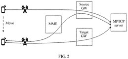
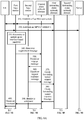
- FIG. 2 a solution of handing over a terminal device supporting the MPTCP is shown in FIG. 2 .
- the UE initiates initialization of the MPTCP connection and establishes an MPTCP subflow 1. Then the UE may perform communication by using the MPTCP subflow 1.
- An address used by the UE is an address (an IP 1) allocated by a source GW.
- the UE When the UE moves and arrives in a cell range in which a target base station is located, the UE first performs a base station handover (that is, a handover from a source base station to the target base station) according to an existing handover procedure, establishes a PDN connection between the target base station and the source GW, and performs communication by using an MPTCP subflow 2 between the UE and the server.
- the target base station After the handover, the target base station establishes a new PDN connection by using a target GW, and the target GW allocates a new IP address (an IP 2) to the UE.
- the UE has two IP addresses (the IP 1 and the IP 2).
- the UE establishes an MPTCP subflow 3 by using the IP 2, then disables MPTCP subflow 2 that is based on the IP 1, and finally releases a PDN connection between the UE and the source GW.
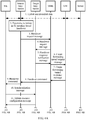
- the UE performs the base station handover according to the existing handover procedure and establishes the PDN connection between the target base station and the source GW: an X2 interface based handover and an S1 interface based handover.
- An X2 interface is mainly configured to transmit data between eNBs, and the X2 interface is configured to forward the data when a terminal moves from one eNB to another.
- FIG. 3 shows an X2 interface based handover procedure:
- An S1 interface is an interface between an eNB and an MME.
- FIG. 4A and FIG. 4B show an S1 interface based handover procedure:
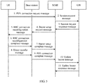
- a PDN connection is an IP connection provided by an EPS system between the UE and an external packet network PDN.
- a PDN connection service may support transmission of one or more service data flows.
- FIG. 5 shows a detailed procedure of establishing a PDN connection:
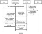
- a process of releasing a PDN connection is as follows:
- a peer end communicating with the UE may be a server or a data network.
- the server is used as an example in this embodiment of this application for description. However, this is not limited in this application.
- the PDN, the GW, and the MME are names in an LTE network architecture, and respectively correspond to a packet data unit (packet data unit, PDU), a forwarding plane network element, and a control plane network element that are in another network.
- PDU packet data unit
- a forwarding plane network element forwarding plane network element
- a control plane network element that are in another network.
- a PDU connection, the forwarding plane network element, and the control plane network element are used as an example in this embodiment of this application for description. However, this is not limited in this application.
- FIG. 7 is an interaction flowchart of a communication method according to an embodiment of this application. It should be noted that this embodiment is merely provided to help a person skilled in the art better understand embodiments of this application, instead of limiting the scope of the embodiments of this application.
- the UE When UE is at a first location, the UE establishes a first PDU connection to a first forwarding plane network element by using a first base station.
- the first location may be any location in a coverage area of the first base station.
- the UE establishes, by using the first base station, the first PDU connection to the first forwarding plane network element corresponding to the first base station, and an IP address allocated by the first forwarding plane network element to the UE is an IP 1.
- the UE sends a PDU connection request to a control plane network element by using the first base station, and the control plane network element finds the first forwarding plane network element by using the first base station, so that the UE establishes the first PDU connection to the first forwarding plane network element by using the first base station.
- a PDU connection process is shown in FIG. 5 . To avoid repetition, details are not described herein.
- the UE initiates initialization of an MPTCP connection, to a server by using the first base station and the first forwarding plane network element based on the IP 1, and establishes an MPTCP sub flow 1. Therefore, the UE may perform communication by using the MPTCP subflow 1.
- the UE may perform communication by using the MPTCP subflow 1.
- the UE and the server may be user terminals that can both support the MPTCP.
- the subflow may be further a connection of the TCP supported by both the UE and the server, a subflow of another improved protocol, or the like.
- An MPTCP subflow is used as an example in this embodiment of this application for description. However, this application is not limited thereto.
- the UE When the UE moves from the first location to a second location, the UE receives a handover preparation message sent by the first base station, where the handover preparation message carries an identity ID of a second base station.
- the UE When the UE moves to the second location (the second location is any location in a coverage area of the second base station), the UE performs a handover from the first base station to the second base station. In this embodiment of this application, the UE performs the handover based on an X2 interface. First, the UE receives the handover preparation message sent by the first base station.
- the handover preparation message may be an RRC mobility control message.
- the first base station sends a measurement message to the UE, to instruct the UE to perform detection on a required measurement parameter.
- the UE performs detection on the measurement parameter according to the measurement message, and reports a measurement report to the first base station.
- the first base station determines, based on the measurement report, a target base station to which the UE is to be handed over, and sends, to the UE, the RRC mobility control message carrying the identity ID of the second base station.
- the server sends downlink data (that is, forwarding data) to the second base station by using the first forwarding plane network element and the first base station in sequence, where the first base station may send the forwarding data to the second base station through a first forwarding tunnel.
- downlink data that is, forwarding data
- this step and step 130 may be simultaneously performed. Alternatively, this step is performed after step 130. This is not limited in this application.
- the UE sends a synchronization message to the second base station based on the identity ID of the second base station, to maintain synchronization between the UE and the second base station.
- the second base station receives the synchronization message, and returns an uplink resource configuration message to the UE.
- the UE receives the uplink resource configuration message, and sends an RRC connection reconfiguration complete message to the second base station, where the connection reconfiguration complete message is used to indicate that the UE has completed a resource configuration, and the RRC connection reconfiguration complete message carries bearer-less handover indication information.
- the UE after the UE accesses the second base station, the UE establishes the PDU connection by using the second base station and the first forwarding plane network element.
- the connection reconfiguration complete message sent to the second base station by the UE carries the bearer-less handover indication information, and the bearer-less handover indication information is used to indicate that the second base station does not need to initiate the PDU connection to the first forwarding plane network element, so that interconnection deployment does not need to be implemented between the second base station and a peripheral forwarding plane network element. This reduces network planning complexity and a handover delay of a service flow path.
- the bearer-less handover indication information may be carried in the RRC connection reconfiguration complete message. Different from the prior art, in FIG. 3 , the bearer-less handover indication information may be alternatively carried in another message before step 170, such as the synchronization message or another message that is not displayed. Alternatively, the bearer-less handover indication information may be independently sent. This is not limited in this application.
- the UE may receive downlink data sent by the second base station.
- the downlink data may be sent by the server by using the first forwarding plane network element, the first base station, and the second base station in sequence in the base station handover process.
- the first base station is connected to the second base station by using the first forwarding tunnel.
- the UE After completing the base station handover, the UE establishes a second PDU connection.
- the UE may establish the second PDU connection to the second base station and a second forwarding plane network element, and the second forwarding plane network element allocates an IP address to the UE.
- the UE establishes, based on the second PDU connection, a second MPTCP subflow for communication.
- the UE establishes an MPTCP subflow 2 to the server based on an IP address (an IP 2) allocated by the second forwarding plane network element, by using the second base station and the second forwarding plane network element.
- an IP 2 allocated by the second forwarding plane network element
- the UE establishes the MPTCP subflow 2 to a peer server by using the IP 2 by sending an SYN/ACK packet of the universal TCP, and the SYN/ACK packet includes an MP_JOIN (MP_JOIN) option to add a TCP connection.
- MP_JOIN MP_JOIN
- a process of establishing an MPTCP subflow is the same as the process of establishing an MPTCP subflow described above. Details are not described herein again. Therefore, the UE may perform communication by using the MPTCP subflow 2.
- the server may send address information including the plurality of IP addresses of the interface of the server to the UE when sending the downlink data to the UE.
- the UE may choose to be connected to an IP address of the interface of the server closest to the UE.
- the UE releases the first PDU connection when a preset moment expires.
- the server may send the downlink data to the second base station through the first forwarding tunnel; and after the base station handover, may send the downlink data to the UE, so that the UE receives the downlink data.
- a timer is triggered. To ensure that all the downlink data can be sent to a greatest extent in the base station handover process and in a process of establishing the second PDU session, the UE releases the first PDU connection when the timer expires at the preset moment.
- the UE adds a REMOVR_ADDR option to a packet transmitted on the MPTCP subflow 2, to instruct the peer server to delete the old address IP 1, and triggers the timer, to ensure that a packet already existing on the MPTCP subflow 1 is sent to the UE.
- a specific process of releasing the PDU connection is shown in FIG. 6 . Details are not described herein again in this embodiment of this application.
- presetting the timer can prevent a loss of a packet that is sent by the server to a source path and that is of the first PDU connection .
- the UE After the UE moves, a connection does not need to be established between the second base station and the first forwarding plane network element, and the downlink data may be sent through the first forwarding tunnel.
- the UE After establishing the second PDU connection by using the second base station and the second forwarding plane network element, the UE establishes, based on the second PDU connection, the MPTCP subflow for communication, triggers the timer, and releases the first PDU connection when the preset moment expires.
- the UE when the UE is in the coverage area of the first base station, the UE performs communication by using the first PDU connection via the first forwarding plane network element. After the UE moves, the UE performs the handover from the first base station to the second base station.
- the UE sends the bearer-less handover indication information to the second base station, and the bearer-less handover indication information is used to instruct the second base station not to establish the connection to the first forwarding plane network element, so that the second base station can avoid, after the UE moves, establishing the connection to the first forwarding plane network element. Therefore, a handover delay of a service flow is reduced.
- sequence numbers of the foregoing processes do not mean execution sequences in the embodiments of this application.
- the execution sequences of the processes should be determined according to functions and internal logic of the processes, and should not be construed as any limitation on the implementation processes of the embodiments of this application.
- FIG. 9A and FIG. 9B are an interaction flowchart of a communication method according to another embodiment of this application. Meanings of terms in this embodiment of this application are the same as those in the foregoing embodiments.
- the UE When UE is at a first location, the UE establishes a first PDU connection to a first forwarding plane network element by using a first base station, so that the UE performs communication by using the first base station and the first forwarding plane network element.
- the first location may be any location in a coverage area of the first base station.
- the UE establishes the first PDU connection to the first forwarding plane network element by using the first base station when the UE is in the coverage area of the first base station, and an IP address allocated by the first forwarding plane network element to the UE is an IP 1.
- the UE sends a PDU connection request to a control plane network element by using the first base station, and the control plane network element finds the first forwarding plane network element by using the first base station, so that the UE establishes the first PDU connection to the first forwarding plane network element by using the first base station.
- a PDU connection process refer to FIG. 5 . Details are not described herein.
- the UE initiates, to a server based on the IP 1, initialization of an MPTCP connection by using the first base station and the first forwarding plane network element, and establishes an MPTCP subflow 1. Therefore, the UE may perform communication by using the MPTCP subflow 1.
- the UE may perform communication by using the MPTCP subflow 1.
- the UE and the server may be user terminals that can both support the MPTCP.
- the subflow may be further a connection of the TCP supported by both the UE and the server, a subflow of another improved protocol, or the like.
- An MPTCP subflow is used as an example in this embodiment of this application for description. However, this application is not limited thereto.
- the first base station determines to initiate an S1 interface based handover.
- the second location may be any location in a coverage area of a second base station
- the first base station sends a measurement message to the UE, to instruct the UE to perform detection on a required measurement parameter.
- the UE performs detection on the measurement parameter according to the measurement message, and reports a measurement report to the first base station.
- the first base station determines, based on the measurement report, to initiate the S1 interface based handover.
- the first base station sends a handover requirement message to the control plane network element.
- the control plane network element sends a handover request message to the second base station based on the handover requirement message.
- the second base station sends a handover request response message to the control plane network element.
- the control plane network element receives the handover request response message, and sends a create forwarding tunnel request message to the first forwarding plane network element, to establish a second forwarding tunnel between the first forwarding plane network element and the second base station.
- the first forwarding plane network element returns a create forwarding tunnel response message to the control plane network element, to indicate completion of establishment of the second forwarding tunnel.
- the control plane network element sends a base station handover command to the first base station, and sends the base station handover command to the UE by using the first base station.
- the first base station sends the base station handover command to the UE, to instruct the UE to perform a base station handover.
- the UE sends a synchronization message to the second base station, to maintain synchronization between the UE and the second base station.
- the second base station receives the synchronization message, and sends an uplink resource configuration message to the UE.
- the UE receives the uplink resource configuration message, and sends a handover complete message to the second base station, where the handover complete message is used to indicate that the UE has completed the base station handover, and the handover complete message carries bearer-less handover indication information.
- an IP address and an uplink/downlink path of a UE service flow need to be anchored at a forwarding plane network element, to ensure IP continuity. Therefore, after accessing the second base station, the UE further establishes a PDU connection by using the second base station and the first forwarding plane network element.
- the UE when performing the handover from the first base station to the second base station, the UE sends, to the second base station, the handover complete message that carries the bearer-less handover indication information, and the bearer-less handover indication information is used to indicate that the second base station does not need to initiate the PDU connection to the first forwarding plane network element, so that interconnection deployment does not need to be implemented between the second base station and a peripheral forwarding plane network element.
- the bearer-less handover indication information may be alternatively carried in an RRC connection reconfiguration complete message. Different from the prior art, in FIG. 4A and FIG. 4B , the bearer-less handover indication information may be alternatively carried in another message before the handover complete message, such as the synchronization message or another message that is not displayed. Alternatively, the bearer-less handover indication information may be independently sent. This is not limited in this application.
- the second base station After receiving the handover complete message, the second base station sends a handover notification message to the control plane network element, to notify the control plane network element that the UE has completed the base station handover.
- the UE may further send the RRC connection reconfiguration complete message to the second base station based on the uplink resource configuration message. This is not limited in this application. It should be further understood that the bearer-less handover indication information may be alternatively carried in the RRC connection reconfiguration complete message. This is not limited in this application.
- the UE may receive downlink data sent by the second base station.
- the UE receives the downlink data sent by the second base station.
- the downlink data is sent by the server to the UE by using the first forwarding plane network element, the first base station, the first forwarding plane network element, and the second base station in sequence in a base station handover process.
- the UE After completing the base station handover, the UE establishes a second PDU connection.
- the UE may establish the second PDU connection by using the second base station and a second forwarding plane network element, and the second forwarding plane network element allocates an address IP 2 to the UE.
- the UE establishes, based on the second PDU connection, a second MPTCP subflow for communication.
- the UE establishes an MPTCP subflow 2 to the server based on the address IP 2 by using the second base station and the second forwarding plane network element.
- a process of initiating an MPTCP subflow is the same as the process of establishing an MPTCP subflow described above. Details are not described herein again. Therefore, the UE performs communication by using the MPTCP subflow 2.
- the server may send address information including the plurality of IP addresses of the interface of the server to the UE when sending the downlink data to the UE.
- the UE may choose to be connected to an IP address of the interface of the server closest to the UE.
- the UE releases the first PDU connection when a preset moment expires.
- the server may send the downlink data to the second base station by using the first forwarding plane network element, the first base station, and the first forwarding plane network element in sequence.
- the UE may send the downlink data to the UE. Therefore, to ensure that all the downlink data can be sent to a greatest extent in the handover process, the UE releases the first PDU connection when the preset moment expires. In this way, presetting the timer can prevent a loss of a packet that is sent by the server to a source path and that is of the first PDU connection.
- the UE adds a REMOVR_ADDR option to a packet transmitted on the MPTCP subflow 2, to instruct a peer server to delete the old address IP 1, and triggers the timer. This ensures that a packet already existing on the MPTCP subflow 1 may be sent to the UE.
- a specific process of releasing the PDU connection refer to FIG. 6 . Details are not described herein again in this embodiment of this application.
- the UE after the UE moves, a connection does not need to be established between the second base station and the first forwarding plane network element, and the downlink data may be sent through the second forwarding tunnel.
- the UE After establishing the second PDU connection by using the second base station and the second forwarding plane network element, the UE establishes, based on the second PDU connection, the MPTCP subflow for communication, triggers the timer, and releases the first PDU connection when the preset moment expires.
- the UE when the UE is in the coverage area of the first base station, the UE performs communication by using the first PDU connection via the first forwarding plane network element. After the UE moves, the UE performs the handover from the first base station to the second base station.
- the UE sends the bearer-less handover indication information to the second base station, and the bearer-less handover indication information is used to instruct the second base station not to establish the connection to the first forwarding plane network element, so that the second base station can avoid, after the UE moves, establishing the connection to the first forwarding plane network element. Therefore, a handover delay of a service flow is reduced.
- sequence numbers of the foregoing processes do not mean execution sequences in the embodiments of this application.
- the execution sequences of the processes should be determined according to functions and internal logic of the processes, and should not be construed as any limitation on the implementation processes of the embodiments of this application.
- FIG. 11 is an interaction flowchart of a communication method according to another embodiment of this application. Meanings of terms in this embodiment of this application are the same as those in the foregoing embodiments.
- the UE When UE is at a first location, the UE establishes a first PDU connection to a first forwarding plane network element by using a first base station, so that the UE performs communication by using the first base station and the first forwarding plane network element.
- the first location may be any location in a coverage area of the first base station.
- the first PDU connection is established between the UE and the first forwarding plane network element, and an IP address allocated by the first forwarding plane network element to the UE is an IP 1.
- the UE sends a PDU connection request to a control plane network element by using the first base station, and the control plane network element finds the first forwarding plane network element by using the first base station, so as to establish the first PDU connection between the UE and the first forwarding plane network element.
- a PDU connection process refer to FIG. 5 . Details are not described herein.
- the UE initiates, to a server based on the IP 1, initialization of an MPTCP connection by using the first base station and the first forwarding plane network element, and establishes an MPTCP subflow 1. Therefore, the UE may perform communication by using the MPTCP subflow 1.
- the UE and the server are user terminals that can both support the MPTCP.
- the subflow may be further a connection of the TCP protocol supported by both the UE and the server, a subflow of another improved protocol, or the like.
- An MPTCP subflow is used as an example in this embodiment of this application for description. However, this application is not limited thereto.
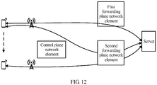
- the UE When the UE needs to move from the first location to a second location, the UE obtains a handover preparation message, where the handover preparation message carries an identity ID of a second base station.
- the UE may send a PDU connection request message to the control plane network element, where the PDU connection request message carries the identity ID of the second base station.
- the control plane network element determines a second forwarding plane network element based on the identity ID of the second base station, so as to establish a third PDU connection, where the third PDU connection is used by the UE to perform communication by using the first base station and the second forwarding plane network element.
- control plane network element establishes the PDU connection based on the ID includes:
- control plane network element may determine the second forwarding plane network element in advance based on the ID of the second base station, so that the UE may establish the PDU connection (which may be indicated as the third PDU connection) by using the first base station and the second forwarding plane network element.
- the PDU connection request message may further carry other information and the like required for establishing the third PDU connection. This is not limited in this embodiment of this application.
- the UE establishes an MPTCP subflow 3 based on an IP address allocated by the second forwarding plane network element, and the UE performs communication by using the MPTCP sub flow 3.
- the UE performs a base station handover from the first base station to the second base station when moving to the second location.
- the base station handover may be an S1 interface based base station handover or an X2 interface based base station handover.
- a specific base station handover process includes step 2 to step 15 in FIG. 3 , or includes step 2 to step 22 in FIG. 4A and FIG. 4B .
- the UE completes a PDU connection (which may be indicated as a second PDU connection) by using the second base station and the second forwarding plane network element.
- the second PDU connection is used by the UE to perform communication by using the second base station and the second forwarding plane network element.
- the UE performs the S1 interface based base station handover or the X2 interface based base station handover.
- the UE receives downlink data sent by the second base station, it indicates that the UE has completed the base station handover from the first base station to the second base station.
- the downlink data may be sent by the server by using the second forwarding plane network element, the first base station, and the second base station in sequence.
- the downlink data may be sent by the server to the UE by using the second forwarding plane network element, the first base station, the second forwarding plane network element, and the second base station in sequence.
- the UE completes the base station handover, in other words, completes a handover of an MPTCP subflow, and performs communication by using an MPTCP subflow 2 that is handed over.
- the UE After the UE performs communication by using the MPTCP subflow 2, the UE releases the first PDU connection.
- the UE may disable the MPTCP subflow 1, and release the first PDU connection. To avoid repetition of a specific procedure, details are not described again.
- the UE when the UE needs to move, the UE obtains the ID of the second base station, selects the second forwarding plane network element based on the ID, establishes the third PDU connection to the first base station and the second forwarding plane network element, and performs communication by using the third PDU connection.
- the UE After the UE moves to the second location and completes the base station handover, the UE establishes the second PDU connection to the second base station and the second forwarding plane network element, establishes, based on the second PDU connection, the MPTCP subflow for communication, and releases the first PDU connection.
- the UE when the UE needs to move, the UE obtains the identity ID of the second base station in advance, and sends the ID of the second base station to the control plane network element, so that the control plane network element selects the second forwarding plane network element based on the ID of the second base station.
- the UE establishes the third PDU connection by using the first base station and the second forwarding plane network element.
- the UE After the UE performs the handover from the first base station to the second base station, the UE completes establishment of the second PDU connection by using the second base station and the second forwarding plane network element, and performs communication by using the second PDU connection. This avoids a connection established by the UE by using the second base station and the first forwarding plane network element in the handover process, so that a handover delay of a service flow and a requirement on network deployment are reduced.
- sequence numbers of the foregoing processes do not mean execution sequences in the embodiments of this application.
- the execution sequences of the processes should be determined according to functions and internal logic of the processes, and should not be construed as any limitation on the implementation processes of the embodiments of this application.
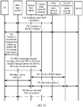
- FIG. 13 is an interaction flowchart of a communication method according to another embodiment of this application. Meanings of terms in this embodiment of this application are the same as those in the foregoing embodiments.
- the UE When UE is at a first location, the UE establishes a first PDU connection to a first forwarding plane network element by using a first base station, so that the UE performs communication by using the first base station and the first forwarding plane network element.
- a base station to which the UE belongs is the first base station.
- the first PDU connection is established between the UE and the first forwarding plane network element, and an IP address allocated by the first forwarding plane network element to the UE is an IP 1.
- the UE sends a PDU connection request to a control plane network element by using the first base station, and the control plane network element finds the first forwarding plane network element by using the first base station, so as to establish the first PDU connection between the UE and the first forwarding plane network element.
- a PDU connection process refer to FIG. 5 . Details are not described herein.
- the UE initiates, to a server based on the IP 1, initialization of an MPTCP connection by using the first base station and the first forwarding plane network element, and establishes an MPTCP subflow 1. Therefore, the UE may perform communication by using the MPTCP subflow 1.
- the UE and the server are user terminals that can both support the MPTCP.
- the subflow may be further a connection of the TCP protocol supported by both the UE and the server, a subflow of another improved protocol, or the like.
- An MPTCP subflow is used as an example in this embodiment of this application for description. However, this application is not limited thereto.
- the UE When the UE needs to move from the first location to a second location, the UE obtains a handover preparation message, where the handover preparation message carries an identity ID of a second base station.
- the UE sends a PDU connection request message to the control plane network element, where the PDU connection request message carries the identity ID of the second base station.
- the control plane network element may select a second forwarding plane network element based on the identity ID of the second base station.
- the control plane network element sets up a default bearer between the second base station and the second forwarding plane network element based on the ID.
- control plane network element establishes the PDU connection based on the identity ID of the second base station includes:
- the control plane network element receives the PDU connection request message, determines the second forwarding plane network element based on the identity ID of the second base station carried in the PDU connection request message, and sends a create session request message to the second forwarding plane network element.
- the second forwarding plane network element returns a create session request response message to the control plane network element.
- the control plane network element sends a bearer setup request message to the second base station.
- the second base station returns a bearer setup response message to the control plane network element.
- the control plane network element sends an update bearer request message to the second forwarding plane network element.
- the second forwarding plane network element returns an update bearer response message to the control plane network element, so as to complete setup of the default bearer between the second base station and a second gateway.
- the UE performs the base station handover from the first base station to the second base station when moving to the second location.
- the base station handover may be an S1 interface based base station handover or an X2 interface based base station handover.
- a specific base station handover process includes step 4 to step 6 in FIG. 3 , or includes step 10 to step 12 in FIG. 4A and FIG. 4B .
- the UE completes a PDU connection (which may be indicated as a second PDU connection) by using the second base station and the second forwarding plane network element.
- the second PDU connection is used by the UE to perform communication by using the second base station and the second forwarding plane network element.
- the UE establishes an MPTCP subflow 2 based on an IP address (an IP 2) allocated by the second forwarding plane network element, and the UE performs communication by using the MPTCP subflow 2.
- an IP address an IP 2 allocated by the second forwarding plane network element
- the UE establishes the MPTCP subflow 2 to a peer server by using the IP 2 by sending an SYN/ACK packet of the universal TCP, and the SYN/ACK packet includes an MP_JOIN (MP_JOIN) option to add a TCP connection, so as to perform communication with the server by using the MPTCP subflow 2.
- MP_JOIN MP_JOIN
- the UE may disable the MPTCP subflow 1, and release the first PDU connection. To avoid repetition of a specific procedure, details are not described again.
- the UE when the UE needs to move, the UE obtains the identity ID of the second base station, selects the second forwarding plane network element based on the ID, establishes the connection between the second base station and the second forwarding plane network element. After the UE moves to the second location and completes the base station handover, the UE completes establishment of the second PDU connection by using the second base station and the second forwarding plane network element, establishes, based on the second PDU connection, the MPTCP subflow for communication, and releases the first PDU connection.
- the UE before moving from the first location to the second location, the UE obtains the identity ID of the second base station, determines, based on the ID of the second base station, the second forwarding plane network element corresponding to the second base station, and establishes the connection between the second base station and the second forwarding plane network element in advance.
- the UE performs communication by using the second PDU connection established between the second base station and the second forwarding plane network element by the UE, so that the UE establishes the connection between the second base station and the second forwarding plane network element in advance when the UE moves, so that a handover delay of a service flow and a requirement on network deployment are reduced.
- sequence numbers of the foregoing processes do not mean execution sequences in the embodiments of this application.
- the execution sequences of the processes should be determined according to functions and internal logic of the processes, and should not be construed as any limitation on the implementation processes of the embodiments of this application.
- FIG. 15 is an interaction flowchart of a communication method according to an embodiment of this application. It should be noted that this embodiment is merely provided to help a person skilled in the art better understand embodiments of this application, instead of limiting the scope of the embodiments of this application.
- the UE When UE is at a first location, the UE establishes a first PDU connection to a first forwarding plane network element by using a first base station. Therefore, the UE may perform communication by using the first PDU connection.
- the UE When the UE moves from the first location to a second location, the UE receives a handover preparation message sent by the first base station, where the handover preparation message carries an identity ID of a second base station.
- the server sends downlink data (that is, forwarding data) to the second base station by using the first forwarding plane network element and the first base station in sequence, where the first base station may send the forwarding data to the second base station through a first forwarding tunnel.
- downlink data that is, forwarding data
- this step and step 920 may be simultaneously performed. Alternatively, this step is performed after step 920. This is not limited in this application.
- the UE sends a synchronization message to the second base station based on the identity ID of the second base station, to maintain synchronization between the UE and the second base station.
- the second base station receives the synchronization message, and returns an uplink resource configuration message to the UE.
- the UE receives the uplink resource configuration message, and sends an RRC connection reconfiguration complete message to the second base station, where the connection reconfiguration complete message is used to indicate that the UE has completed a resource configuration, and the RRC connection reconfiguration complete message carries bearer-less handover indication information.
- the UE may receive downlink data sent by the second base station.
- the downlink data may be sent by the server by using the first forwarding plane network element, the first base station, and the second base station in sequence in a base station handover process.
- the first base station is connected to the second base station by using the first forwarding tunnel.
- the UE After performing the handover from the first base station to the second base station, the UE establishes a second PDU connection by using the second base station and the second forwarding plane network element, and performs communication by using the second PDU connection.
- the UE releases the first PDU connection when a preset moment expires.
- the UE when the UE is in a coverage area of the first base station, the UE performs communication by using the first PDU connection via the first forwarding plane network element. After the UE moves, the UE performs the handover from the first base station to the second base station.
- the UE sends the bearer-less handover indication information to the second base station, and the bearer-less handover indication information is used to instruct the second base station not to establish the connection to the first forwarding plane network element, so that the second base station can avoid, after the UE moves, establishing the connection to the first forwarding plane network element. Therefore, a handover delay of a service flow is reduced.
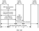
- FIG. 16A and FIG. 16B are an interaction flowchart of a communication method according to another embodiment of this application. Meanings of terms in this embodiment of this application are the same as those in the foregoing embodiments.
- the UE When UE is at a first location, the UE establishes a first PDU connection to a first forwarding plane network element by using a first base station, so that the UE performs communication by using the first base station and the first forwarding plane network element.
- the first base station determines to initiate an S1 interface based handover.
- the first base station sends a handover requirement message to a control plane network element.
- the control plane network element sends a handover request message to a second base station based on the handover requirement message.
- the second base station sends a handover response notification message to the control plane network element.
- the control plane network element receives the handover response notification message, and sends a create forwarding tunnel request message to the first forwarding plane network element, to establish a second forwarding tunnel between the first forwarding plane network element and the second base station.
- the first forwarding plane network element returns a create forwarding tunnel response message to the control plane network element, to indicate completion of establishment of the second forwarding tunnel.
- the control plane network element sends a base station handover command to the first base station, and sends the base station handover command to the UE by using the first base station.
- the first base station sends the base station handover command to the UE, to instruct the UE to perform a base station handover.
- the UE sends a synchronization message to the second base station, to maintain synchronization between the UE and the second base station.
- the second base station receives the synchronization message, and sends an uplink resource configuration message to the UE.
- the UE receives the uplink resource configuration message, and sends a handover complete message to the second base station, where the handover complete message is used to indicate that the UE has completed the base station handover, and the handover complete message carries bearer-less handover indication information.
- an IP address and an uplink/downlink path of a UE service flow need to be anchored at a forwarding plane network element, to ensure IP continuity. Therefore, after the UE completes the base station handover from the first base station to the second base station, the second base station initiates the PDU connection to the first forwarding plane network element.
- the UE in a process of completing the base station handover, sends, to the second base station, the handover complete message that carries the bearer-less handover indication information, and the bearer-less handover indication information is used to indicate that the second base station does not need to initiate the PDU connection to the first forwarding plane network element, so that interconnection deployment does not need to be performed between the second base station and a peripheral forwarding plane network element.
- the bearer-less handover indication information may be alternatively carried in an RRC connection reconfiguration complete message. Different from FIG. 4A and FIG. 4B in the prior art, the bearer-less handover indication information may be alternatively carried in another message before the handover complete message, such as the synchronization message or another message that is not displayed. Alternatively, the bearer-less handover indication information may be independently sent. This is not limited in this application.
- the second base station After receiving the handover complete message, the second base station sends a handover notification message to the control plane network element, to notify the control plane network element that the UE has completed the base station handover.
- the UE After completing the base station handover, the UE establishes a second PDU connection.
- the UE may establish the second PDU connection by using the second base station and a second forwarding plane network element, and the second forwarding plane network element allocates an IP address to the UE.
- the UE releases the first PDU connection when a preset moment expires.
- the UE when the UE is in a coverage area of the first base station, the UE performs communication by using the first PDU connection via the first forwarding plane network element. After the UE moves, the UE performs the handover from the first base station to the second base station.
- the UE sends the bearer-less handover indication information to the second base station, and the bearer-less handover indication information is used to instruct the second base station not to establish the connection to the first forwarding plane network element, so that the second base station can avoid, after the UE moves, establishing the connection to the first forwarding plane network element. Therefore, a handover delay of a service flow is reduced.
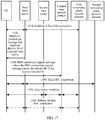
- FIG. 17 is an interaction flowchart of a communication method according to another embodiment of this application. Meanings of terms in this embodiment of this application are the same as those in the foregoing embodiments.
- the UE When UE is at a first location, the UE establishes a first PDU connection to a first forwarding plane network element by using a first base station, so that the UE performs communication by using the first base station and the first forwarding plane network element.
- the UE When the UE needs to move from the first location to a second location, the UE obtains a handover preparation message, where the handover preparation message carries an identity ID of a second base station.
- the UE may send a PDU connection request message to a control plane network element, where the PDU connection request message carries the identity ID of the second base station.
- the control plane network element determines a second forwarding plane network element based on the PDU connection request message, so as to establish a third PDU connection, where the third PDU connection is used by the UE to perform communication by using the first base station and the second forwarding plane network element.
- the UE When moving to the second location, the UE performs a base station handover from the first base station to the second base station, where after the UE completes the base station handover, the UE completes a PDU connection by using the second base station and the second forwarding plane network element, and the second PDU connection is used by the UE to perform communication by using the second base station and the second forwarding plane network element.
- the UE when the UE needs to move, the UE obtains the identity ID of the second base station in advance, and sends the ID of the second base station to the control plane network element, so that the control plane network element establishes the third PDU connection by using the first base station and the second forwarding plane network element based on the ID of the second base station.
- the UE performs the handover from the first base station to the second base station, the UE completes establishment of the second PDU connection by using the second base station and the second forwarding plane network element, and performs communication by using the second PDU connection. This avoids a connection established by the UE by using the second base station and the first forwarding plane network element in a handover process, so that a handover delay of a service flow and a requirement on network deployment are reduced.
- sequence numbers of the foregoing processes do not mean execution sequences in the embodiments of this application.
- the execution sequences of the processes should be determined according to functions and internal logic of the processes, and should not be construed as any limitation on the implementation processes of the embodiments of this application.
- FIG. 18 is an interaction flowchart of a communication method according to another embodiment of this application. Meanings of terms in this embodiment of this application are the same as those in the foregoing embodiments.
- the UE When UE is at a first location, the UE establishes a first PDU connection to a first forwarding plane network element by using a first base station, so that the UE performs communication by using the first base station and the first forwarding plane network element.
- the UE When the UE needs to move from the first location to a second location, the UE obtains a handover preparation message, where the handover preparation message carries an identity ID of a second base station.
- the UE sends a PDU connection request message to a control plane network element, where the PDU connection request message carries the identity ID of the second base station.
- the control plane network element may determine a second forwarding plane network element based on the identity ID of the second base station.
- the control plane network element sets up a default bearer between the second base station and the second forwarding plane network element based on the ID.
- the UE When moving to the second location, the UE performs a base station handover from the first base station to the second base station, where after the UE accesses the second base station, the UE completes a PDU connection (which may be indicated as a second PDU connection) by using the second base station and the second forwarding plane network element, and the second PDU connection is used by the UE to perform communication by using the second base station and the second forwarding plane network element.
- a PDU connection which may be indicated as a second PDU connection
- the control plane network element obtains the ID of the second base station, selects the second forwarding plane network element based on the ID of the second base station, and establishes a connection between the second base station and the second forwarding plane network element in advance.
- the UE After accessing the second base station, the UE performs communication by using the second PDU connection established between the second base station and the second forwarding plane network element by the UE, so that the UE establishes the connection between the second base station and the second forwarding plane network element in advance when the UE moves, so that a handover delay of a service flow and a requirement on network deployment are reduced.
- FIG. 19 is a schematic block diagram of user equipment 1700 according to an embodiment of this application. As shown in FIG. 19 , the user equipment 1700 includes:
- the sending module 1720 is specifically configured to: send a connection reconfiguration complete message to the second base station, where the connection reconfiguration complete message carries the bearer-less handover indication information.
- the UE 1700 further includes:
- the UE 1700 further includes: a release module, configured to release the first PDU connection when a preset time threshold is reached.
- a release module configured to release the first PDU connection when a preset time threshold is reached.
- the user equipment 1700 in this embodiment of this application may correspond to the user equipment in the communication method in the embodiment of this application, and the foregoing and other operations and/or functions of the modules in the user equipment 1700 are separately intended for implementing corresponding procedures in the foregoing methods. For brevity, details are not described herein again.
- the UE provided in this embodiment of this application performs communication by using the first PDU connection via the first forwarding plane network element. After the UE moves, the UE performs the handover from the first base station to the second base station.
- the UE sends the bearer-less handover indication information to the second base station, and the bearer-less handover indication information is used to instruct the second base station not to establish the connection to the first forwarding plane network element, so that the second base station can avoid, after the UE moves, establishing the connection to the first forwarding plane network element. Therefore, a handover delay of a service flow is reduced.
- FIG. 20 is a schematic block diagram of a base station 1900 according to an embodiment of this application. As shown in FIG. 20 , the base station 1900 includes:
- the receiving module 1910 is specifically configured to: receive a handover complete message sent by the UE, where the handover complete message carries bearer-less handover indication information.
- the second base station 1900 in this embodiment of this application may correspond to the base station in the communication method in the embodiment of this application, and the foregoing and other operations and/or functions of the modules in the second base station 1900 are separately intended for implementing corresponding procedures in the foregoing methods. For brevity, details are not described herein again.
- the second base station in this embodiment of this application receives the bearer-less handover indication information sent by the UE, and determines, according to the bearer-less handover indication information, not to establish the connection to the first forwarding plane network element, so that a handover delay of a service flow and a requirement on network deployment are reduced.
- FIG. 21 is a schematic block diagram of UE 2000 according to an embodiment of this application. As shown in FIG. 21 , the UE 2000 includes:
- the UE 2000 further includes: a communications module, configured to perform communication by using the PDU connection.
- the UE in this embodiment of this application obtains the identity ID of the second base station in advance, and sends the ID of the second base station to the control plane network element, so that the control plane network element selects the second forwarding plane network element based on the ID of the second base station, and the PDU connection is established between the UE and the second forwarding plane network element.
- This avoids a connection established by the UE by using the second base station and a first forwarding plane network element in a handover process, so that a handover delay of a service flow and a requirement on network deployment are reduced.
- the user equipment 2000 in this embodiment of this application may correspond to the user equipment in the embodiment of this application, and the foregoing and other operations and/or functions of the modules in the user equipment 2000 are separately intended for implementing corresponding procedures in the foregoing methods. For brevity, details are not described herein again.
- FIG. 22 is a schematic block diagram of a control plane network element 2100 according to an embodiment of this application. As shown in FIG. 22 , the control plane network element 2100 includes:
- the control plane network element in this embodiment of this application receives the identity ID of the second base station sent by the UE, selects the second forwarding plane network element based on the ID of the second base station, and establishes the PDU connection between the UE and the second forwarding plane network element. This avoids a connection established by the UE by using the second base station and the first forwarding plane network element in a handover process, so that a handover delay of a service flow and a requirement on network deployment are reduced.
- processing module 2120 is specifically configured to:
- processing module 2120 is specifically configured to:
- the control plane network element in this embodiment of this application receives the identity ID of the second base station sent by the UE, selects the second forwarding plane network element based on the ID of the second base station, and establishes the PDU connection between the UE and the second forwarding plane network element. This avoids a connection established by the UE by using the second base station and the first forwarding plane network element in a handover process, so that a handover delay of a service flow and a requirement on network deployment are reduced.
- control plane network element 2100 in this embodiment of this application may correspond to the control plane network element in the communication method in the embodiment of this application, and the foregoing and other operations and/or functions of the modules in the control plane network element 2100 are separately intended for implementing corresponding procedures in the foregoing methods. For brevity, details are not described herein again.
- An embodiment of this application further provides a communications system 2200.
- the communications system 2200 includes: the UE 1700 in the foregoing embodiment of this application and the base station 1900 in the embodiment of this application.
- An embodiment of this application further provides a communications system 2300.
- the communications system 2300 includes: the UE 2000 in the foregoing embodiment of this application and the control plane network element 2100 in the embodiment of this application.
- FIG. 25 shows a structure of UE according to still another embodiment of this application.
- the UE includes at least one processor 2402 (such as a general purpose processor CPU having computing and processing capabilities, a digital signal processor (DSP), an application-specific integrated circuit (ASIC), or a field programmable gate array (FPGA)).
- the processor manages and schedules modules and devices in the user equipment.
- the UE further includes at least one network interface 2405 or another communications interface, a memory 2406, and at least one bus system 2403. Components of the user equipment are coupled together by using the bus system 2403.
- the bus system 2403 may include a data bus, a power bus, a control bus, a signal status bus, and the like. However, for clear description, all the buses in the figure are marked as the bus system 2403.
- the method disclosed in the embodiment of this application may be applied to the processor 2402, or is used to execute an executable module stored in the memory 2406, for example, a computer program.
- the memory 2406 may include a high speed random access memory (RAM, Random Access Memory), or may include a non-volatile memory (non-volatile memory).
- the memory may include a read-only memory and a random access memory, and provide required signaling or data, a required program, and the like for the processor.
- a part of the memory may further include a non-volatile random access memory (NVRAM).
- a communication connection to at least one another network element is implemented by using the at least one network interface 2405 (which may be wired or wireless).
- the memory 2406 stores a program 24061, and the processor 2402 executes the program 24061, to perform the following operations:
- the user equipment may be specifically the user equipment in the foregoing embodiment, and may be configured to perform the steps and/or procedures corresponding to the user equipment in the foregoing method embodiment.
- the UE when the UE is in a coverage area of the first base station, the UE performs communication by using the first PDU connection via the first forwarding plane network element. After the UE moves, the UE performs the handover from the first base station to the second base station.
- the UE sends the bearer-less handover indication information to the second base station, and the bearer-less handover indication information is used to instruct the second base station not to establish the connection to the first forwarding plane network element, so that the second base station can avoid, after the UE moves, establishing the connection to the first forwarding plane network element. Therefore, a handover delay of a service flow is reduced.
- the UE 2400 in this embodiment of this application may correspond to the user equipment in the communication method in the embodiment of this application, and the foregoing and other operations and/or functions of the modules in the UE 2400 are separately intended for implementing corresponding procedures in the foregoing methods. For brevity, details are not described herein again.
- FIG. 26 shows a structure of a base station according to still another embodiment of this application.
- the base station includes at least one processor 2502 (such as a general purpose processor CPU having computing and processing capabilities, a digital signal processor (DSP), an application-specific integrated circuit (ASIC), or a field programmable gate array (FPGA)).
- the base station further includes at least one network interface 2505 or another communications interface, a memory 2506, and at least one bus system 2503. Components of the base station are coupled together by using the bus system 2503.
- the bus system 2503 may include a data bus, a power bus, a control bus, a signal status bus, and the like. However, for clear description, all the buses in the figure are marked as the bus system 2503.
- the method disclosed in the embodiment of this application may be applied to the processor 2502, or is used to execute an executable module stored in the memory 2506, for example, a computer program.
- the memory 2506 may include a high speed random access memory (RAM, Random Access Memory), or may include a non-volatile memory (non-volatile memory).
- the memory may include a read-only memory and a random access memory, and provide required signaling or data, a required program, and the like for the processor.
- a part of the memory may further include a non-volatile random access memory (NVRAM).
- a communication connection to at least one another network element is implemented by using the at least one network interface 2505 (which may be wired or wireless).
- the memory 2506 stores a program 25061, and the processor 2502 executes the program 25061, to perform the following operations:
- the base station may be specifically the base station in the foregoing embodiment, and may be configured to perform the steps and/or procedures corresponding to the base station in the foregoing method embodiment.
- the second base station receives the bearer-less handover indication information sent by the UE, and determines, according to the bearer-less handover indication information, not to establish the connection to the first forwarding plane network element, so that a handover delay of a service flow and a requirement on network deployment are reduced.
- the base station 2500 in this embodiment of this application may correspond to the second base station in the communication method in the embodiment of this application, and the foregoing and other operations and/or functions of the modules in the base station 2500 are separately intended for implementing corresponding procedures in the foregoing methods. For brevity, details are not described herein again.
- FIG. 27 shows a structure of UE according to still another embodiment of this application.
- the UE includes at least one processor 2602 (such as a general purpose processor CPU having computing and processing capabilities, a digital signal processor (DSP), an application-specific integrated circuit (ASIC), or a field programmable gate array (FPGA)).
- the processor manages and schedules modules and devices in the user equipment.
- the UE further includes at least one network interface 2605 or another communications interface, a memory 2606, and at least one bus system 2603. Components of the user equipment are coupled together by using the bus system 2603.
- the bus system 2603 may include a data bus, a power bus, a control bus, a signal status bus, and the like. However, for clear description, all the buses in the figure are marked as the bus system 2603.
- the method disclosed in the embodiment of this application may be applied to the processor 2602, or is used to execute an executable module stored in the memory 2606, for example, a computer program.
- the memory 2606 may include a high speed random access memory (RAM, Random Access Memory), or may include a non-volatile memory (non-volatile memory).
- the memory may include a read-only memory and a random access memory, and provide required signaling or data, a required program, and the like for the processor.
- a part of the memory may further include a non-volatile random access memory (NVRAM).
- a communication connection to at least one another network element is implemented by using the at least one network interface 2605 (which may be wired or wireless).
- the memory 2606 stores a program 26061, and the processor 2602 executes the program 26061, to perform the following operations:
- the user equipment may be specifically the user equipment in the foregoing embodiment, and may be configured to perform the steps and/or procedures corresponding to the user equipment in the foregoing method embodiment.
- the UE when the UE needs to move, the UE obtains the identity ID of the second base station in advance, and sends the ID of the second base station to the control plane network element, so that the control plane network element selects the second forwarding plane network element based on the ID of the second base station, and the PDU connection is established between the UE and the second forwarding plane network element.
- This avoids a connection established by the UE by using the second base station and a first forwarding plane network element in a handover process, so that a handover delay of a service flow and a requirement on network deployment are reduced.
- the UE 2600 in this embodiment of this application may correspond to the user equipment in the communication method in the embodiment of this application, and the foregoing and other operations and/or functions of the modules in the UE 2600 are separately intended for implementing corresponding procedures in the foregoing methods. For brevity, details are not described herein again.
- FIG. 28 shows a structure of a control plane network element according to another embodiment of this application.
- the control plane network element includes at least one processor 2702 (such as a general purpose processor CPU having computing and processing capabilities, a digital signal processor (DSP), an application-specific integrated circuit (ASIC), or a field programmable gate array (FPGA)).
- the control plane network element further includes at least one network interface 2705 or another communications interface, a memory 2706, and at least one bus system 2703. Components of the control plane network element are coupled together by using the bus system 2703.
- the bus system 2703 may include a data bus, a power bus, a control bus, a signal status bus, and the like. However, for clear description, all the buses in the figure are marked as the bus system 2703.
- the method disclosed in the embodiment of this application may be applied to the processor 2702, or is used to execute an executable module stored in the memory 2706, for example, a computer program.
- the memory 2706 may include a high speed random access memory (RAM, Random Access Memory), or may include a non-volatile memory (non-volatile memory).
- the memory may include a read-only memory and a random access memory, and provide required signaling or data, a required program, and the like for the processor.
- a part of the memory may further include a non-volatile random access memory (NVRAM).
- a communication connection to at least one another network element is implemented by using the at least one network interface 2705 (which may be wired or wireless).
- the memory 2706 stores a program 27061, and the processor 2702 executes the program 27061, to perform the following operations:
- control plane network element may be specifically the control plane network element in the foregoing embodiment, and may be configured to perform the steps and/or procedures corresponding to the control plane network element in the foregoing method embodiment.
- the control plane network element receives the identity ID of the second base station sent by the UE, selects the second forwarding plane network element based on the ID of the second base station, and establishes the PDU connection between the UE and the second forwarding plane network element. This avoids a connection established by the UE by using the second base station and the first forwarding plane network element in a handover process, so that a handover delay of a service flow and a requirement on network deployment are reduced.
- control plane network element 2700 in this embodiment of this application may correspond to the control plane network element in the communication method in the embodiment of this application, and the foregoing and other operations and/or functions of the modules in the control plane network element 2700 are separately intended for implementing corresponding procedures in the foregoing methods. For brevity, details are not described herein again.
- An embodiment of this application further provides a computer storage medium, where the computer storage medium may store a program instruction used to indicate any one of the foregoing methods.
- the storage medium may be specifically any one of the memory 2406, the memory 2506, the memory 2606, and the memory 2706.
- sequence numbers of the foregoing processes do not mean execution sequences in the embodiments of this application.
- the execution sequences of the processes should be determined according to functions and internal logic of the processes, and should not be construed as any limitation on the implementation processes of the embodiments of this application.
- the disclosed system, apparatus, and method may be implemented in other manners.
- the described apparatus embodiment is merely an example.
- the unit division is merely logical function division and may be other division in actual implementation.
- a plurality of units or components may be combined or integrated into another system, or some features may be ignored or not performed.
- the displayed or discussed mutual couplings or direct couplings or communication connections may be implemented by using some interfaces.
- the indirect couplings or communication connections between the apparatuses or units may be implemented in electronic, mechanical, or other forms.
- the units described as separate parts may or may not be physically separate, and parts displayed as units may or may not be physical units, may be located in one position, or may be distributed on a plurality of network units. Some or all of the units may be selected based on actual requirements to achieve the objectives of the solutions of the embodiments.
- function units in the embodiments of this application may be integrated into one processing unit, or each of the units may exist alone physically, or two or more units are integrated into one unit.
- the integrated unit may be implemented in a form of hardware, or may be implemented in a form of a software function unit.
- the integrated unit When the integrated unit is implemented in the form of a software function unit and sold or used as an independent product, the integrated unit may be stored in a computer-readable storage medium. Based on such an understanding, the technical solutions of this application essentially, or the part contributing to the prior art, or some of the technical solutions may be implemented in a form of a software product.
- the software product is stored in a storage medium and includes several instructions for instructing a computer device (which may be a personal computer, a server, a network device, or the like) to perform all or some of the steps of the methods described in the embodiments of this application.
- the foregoing storage medium includes: any medium that can store program code, such as a USB flash drive, a removable hard disk, a read-only memory (ROM, Read-Only Memory), a random access memory (RAM, Random Access Memory), a magnetic disk, or an optical disc.
- program code such as a USB flash drive, a removable hard disk, a read-only memory (ROM, Read-Only Memory), a random access memory (RAM, Random Access Memory), a magnetic disk, or an optical disc.
Landscapes
- Engineering & Computer Science (AREA)
- Computer Networks & Wireless Communication (AREA)
- Signal Processing (AREA)
- Databases & Information Systems (AREA)
- Mobile Radio Communication Systems (AREA)
Applications Claiming Priority (1)
| Application Number | Priority Date | Filing Date | Title |
|---|---|---|---|
| PCT/CN2016/093217 WO2018023544A1 (zh) | 2016-08-04 | 2016-08-04 | 通信方法、用户设备、基站、控制面网元和通信系统 |
Publications (3)
| Publication Number | Publication Date |
|---|---|
| EP3481101A1 true EP3481101A1 (de) | 2019-05-08 |
| EP3481101A4 EP3481101A4 (de) | 2019-07-31 |
| EP3481101B1 EP3481101B1 (de) | 2025-10-08 |
Family
ID=61072545
Family Applications (1)
| Application Number | Title | Priority Date | Filing Date |
|---|---|---|---|
| EP16911141.6A Active EP3481101B1 (de) | 2016-08-04 | 2016-08-04 | Kommunikationsverfahren, benutzergerät, basisstation, steuerungsebenennetzwerkelement und kommunikationssystem |
Country Status (5)
| Country | Link |
|---|---|
| US (1) | US10841848B2 (de) |
| EP (1) | EP3481101B1 (de) |
| CN (1) | CN108702656B (de) |
| RU (1) | RU2719366C1 (de) |
| WO (1) | WO2018023544A1 (de) |
Cited By (1)
| Publication number | Priority date | Publication date | Assignee | Title |
|---|---|---|---|---|
| CN113556787A (zh) * | 2020-04-23 | 2021-10-26 | 大唐移动通信设备有限公司 | 一种专网业务数据传输方法及装置 |
Families Citing this family (5)
| Publication number | Priority date | Publication date | Assignee | Title |
|---|---|---|---|---|
| JP2020036055A (ja) * | 2017-01-05 | 2020-03-05 | シャープ株式会社 | 端末装置、コアネットワーク装置、及び通信制御方法 |
| US20220322489A1 (en) * | 2019-10-11 | 2022-10-06 | Nec Corporation | Controlling and restricting of user identities per ue |
| TWI793399B (zh) * | 2020-02-14 | 2023-02-21 | 緯創資通股份有限公司 | 使用者裝置及資料流量傳遞之排程方法 |
| CN112020112B (zh) * | 2020-07-27 | 2021-10-01 | 北京邮电大学 | Sdn架构下基于mptcp的异构网络切换方法和系统 |
| CN114071606B (zh) * | 2020-08-06 | 2023-10-27 | 北京佰才邦技术股份有限公司 | 一种切换方法、装置及控制设备 |
Family Cites Families (19)
| Publication number | Priority date | Publication date | Assignee | Title |
|---|---|---|---|---|
| KR101221898B1 (ko) | 2005-06-14 | 2013-01-15 | 엘지전자 주식회사 | 이동 통신 시스템에서의 시그널링 방법 |
| CN101365239B (zh) * | 2007-08-09 | 2012-12-12 | 华为技术有限公司 | 数据转发的方法、演进基站和长期演进网络 |
| CN101453765B (zh) * | 2007-12-04 | 2012-07-04 | 华为技术有限公司 | 网络切换的方法、系统及装置 |
| EP2273820A1 (de) * | 2009-06-30 | 2011-01-12 | Panasonic Corporation | Inter-VPLMN-Übergabe über einen Übergabeproxyknoten |
| US8811307B2 (en) * | 2009-07-17 | 2014-08-19 | Htc Corporation | Method of handling long term evaluation positioning protocol data and related communication device |
| JP5893554B2 (ja) * | 2010-04-14 | 2016-03-23 | シャープ株式会社 | 位置管理装置、パケットデータネットワークゲートウェイ装置、移動局装置及び位置管理装置の通信方法 |
| CN102065429B (zh) * | 2010-12-28 | 2013-06-26 | 广州杰赛科技股份有限公司 | 一种安全的无线城域网的用户终端切换方法 |
| CN103517356B (zh) * | 2012-06-28 | 2017-04-05 | 电信科学技术研究院 | 一种进行切换的方法、系统和设备 |
| EP2898639A1 (de) * | 2012-09-24 | 2015-07-29 | Telefonaktiebolaget L M Ericsson (publ) | Verkehrsformung und -lenkung für eine verbindung mit einem mehrwegübertragungs-steuerungsprotokoll |
| CN104602307A (zh) * | 2013-10-30 | 2015-05-06 | 北京三星通信技术研究有限公司 | 切换方法及系统 |
| EP3085192B1 (de) * | 2013-12-18 | 2019-03-06 | Telefonaktiebolaget LM Ericsson (publ) | Aufbau eines mehrpfad-tcp-subflows auf einer einzigen ip-verbindung |
| EP3100569B1 (de) * | 2014-01-31 | 2019-02-20 | Telefonaktiebolaget LM Ericsson (publ) | Verfahren zwischen zwei enbs zur zustimmung zu einer funkressourcenkonfiguration für eine die doppelkonnektivität zwischen enbs unterstützende benutzereinheit |
| EP3132622B1 (de) * | 2014-04-15 | 2019-09-25 | Nokia Solutions and Networks Oy | Zusammenarbeit mit trägerbasiertem system |
| US10104582B2 (en) * | 2014-08-11 | 2018-10-16 | Cisco Technology, Inc. | Call preservation on handover |
| WO2016049933A1 (zh) * | 2014-09-30 | 2016-04-07 | 华为技术有限公司 | 多路径传输控制协议通信的地址管理装置、系统及方法 |
| EP3266273A1 (de) * | 2015-03-06 | 2018-01-10 | Telefonaktiebolaget LM Ericsson (publ) | Verfahren und kommunikationsknoten zur datenverkehrsaggregation |
| US10512001B2 (en) * | 2015-08-17 | 2019-12-17 | Lg Electronics Inc. | Method for rearranging gateway and method for generating dedicated bearer |
| EP3459217B1 (de) * | 2016-05-16 | 2020-07-08 | Telefonaktiebolaget LM Ericsson (PUBL) | Transport von udp-paketen über eine mptcp-verbindung |
| US10159101B2 (en) * | 2016-05-20 | 2018-12-18 | Blackberry Limited | Using WLAN connectivity of a wireless device |
-
2016
- 2016-08-04 EP EP16911141.6A patent/EP3481101B1/de active Active
- 2016-08-04 CN CN201680082267.7A patent/CN108702656B/zh active Active
- 2016-08-04 RU RU2019105707A patent/RU2719366C1/ru active
- 2016-08-04 WO PCT/CN2016/093217 patent/WO2018023544A1/zh not_active Ceased
-
2019
- 2019-01-31 US US16/263,962 patent/US10841848B2/en active Active
Cited By (2)
| Publication number | Priority date | Publication date | Assignee | Title |
|---|---|---|---|---|
| CN113556787A (zh) * | 2020-04-23 | 2021-10-26 | 大唐移动通信设备有限公司 | 一种专网业务数据传输方法及装置 |
| CN113556787B (zh) * | 2020-04-23 | 2022-10-04 | 大唐移动通信设备有限公司 | 一种专网业务数据传输方法及装置 |
Also Published As
| Publication number | Publication date |
|---|---|
| EP3481101A4 (de) | 2019-07-31 |
| EP3481101B1 (de) | 2025-10-08 |
| US20190166532A1 (en) | 2019-05-30 |
| US10841848B2 (en) | 2020-11-17 |
| WO2018023544A1 (zh) | 2018-02-08 |
| CN108702656A (zh) | 2018-10-23 |
| CN108702656B (zh) | 2021-02-09 |
| RU2719366C1 (ru) | 2020-04-17 |
Similar Documents
| Publication | Publication Date | Title |
|---|---|---|
| TWI722534B (zh) | 協定資料單元會話切換衝突之處理方法及其使用者設備 | |
| US10841848B2 (en) | Communication method, user equipment, base station, control plane network element, and communications system | |
| TWI733216B (zh) | 無效協定資料單元會話之處理方法及其使用者設備 | |
| CN106063328B (zh) | 一种切换装置及方法 | |
| KR102484223B1 (ko) | Pdu 세션 활성화 방법, 페이징 방법 및 그의 장치 | |
| CN108028783B (zh) | 切换移动边缘平台的方法、装置和系统 | |
| JP5010690B2 (ja) | セキュリティ機能ネゴシエーション方法、システム、および装置 | |
| JP4918616B2 (ja) | 最適化Inter−RAT切換を実装するための方法およびシステム | |
| CN102742322B (zh) | 将用户设备返回源无线接入网 | |
| US10869342B2 (en) | Radio bearer establishment method and base station | |
| EP4017102A1 (de) | Verfahren, endgerät und netzwerkvorrichtung zur übertragung von daten | |
| WO2020147761A1 (zh) | 一种pdu会话切换方法及其装置 | |
| EP2999265B1 (de) | Verfahren, vorrichtung und system zur netzwerkübergabe | |
| CN112312489B (zh) | 传输数据的方法、通信装置和通信系统 | |
| CN101370261B (zh) | 从cs域向ps域切换的资源准备方法及通信设备 | |
| JP6198940B2 (ja) | デフォルト・ベアラなしのハンドオーバのための方法および装置 | |
| WO2021027932A1 (zh) | 信息处理方法、装置、设备及计算机可读存储介质 | |
| US10602404B2 (en) | Data offloading method and base station | |
| CN103782628A (zh) | 通信方法、设备和系统 | |
| US20150341984A1 (en) | Data exchange method and apparatus | |
| WO2015062087A1 (zh) | 一种网络切换的方法、设备及系统 | |
| WO2015062643A1 (en) | Keeping user equipment in a state attached to a cellular communication network during offloading of cellular data to another communication network | |
| CN101494885A (zh) | 一种多承载共享的ambr切换控制方法 | |
| CN102413461B (zh) | 安全能力协商的方法及系统 | |
| WO2013123783A1 (zh) | 确定源sgsn的方法和装置 |
Legal Events
| Date | Code | Title | Description |
|---|---|---|---|
| STAA | Information on the status of an ep patent application or granted ep patent |
Free format text: STATUS: THE INTERNATIONAL PUBLICATION HAS BEEN MADE |
|
| PUAI | Public reference made under article 153(3) epc to a published international application that has entered the european phase |
Free format text: ORIGINAL CODE: 0009012 |
|
| STAA | Information on the status of an ep patent application or granted ep patent |
Free format text: STATUS: REQUEST FOR EXAMINATION WAS MADE |
|
| 17P | Request for examination filed |
Effective date: 20190130 |
|
| AK | Designated contracting states |
Kind code of ref document: A1 Designated state(s): AL AT BE BG CH CY CZ DE DK EE ES FI FR GB GR HR HU IE IS IT LI LT LU LV MC MK MT NL NO PL PT RO RS SE SI SK SM TR |
|
| AX | Request for extension of the european patent |
Extension state: BA ME |
|
| A4 | Supplementary search report drawn up and despatched |
Effective date: 20190703 |
|
| RIC1 | Information provided on ipc code assigned before grant |
Ipc: H04W 36/08 20090101ALI20190627BHEP Ipc: H04W 36/00 20090101AFI20190627BHEP |
|
| DAV | Request for validation of the european patent (deleted) | ||
| DAX | Request for extension of the european patent (deleted) | ||
| STAA | Information on the status of an ep patent application or granted ep patent |
Free format text: STATUS: EXAMINATION IS IN PROGRESS |
|
| 17Q | First examination report despatched |
Effective date: 20210518 |
|
| REG | Reference to a national code |
Ref country code: DE Free format text: PREVIOUS MAIN CLASS: H04W0036000000 Ipc: H04W0056000000 Ref country code: DE Ref legal event code: R079 Ref document number: 602016093773 Country of ref document: DE Free format text: PREVIOUS MAIN CLASS: H04W0036000000 Ipc: H04W0056000000 |
|
| GRAP | Despatch of communication of intention to grant a patent |
Free format text: ORIGINAL CODE: EPIDOSNIGR1 |
|
| STAA | Information on the status of an ep patent application or granted ep patent |
Free format text: STATUS: GRANT OF PATENT IS INTENDED |
|
| RIC1 | Information provided on ipc code assigned before grant |
Ipc: H04W 36/08 20090101ALI20250408BHEP Ipc: H04W 36/00 20090101ALI20250408BHEP Ipc: H04W 56/00 20090101AFI20250408BHEP |
|
| INTG | Intention to grant announced |
Effective date: 20250502 |
|
| RIN1 | Information on inventor provided before grant (corrected) |
Inventor name: YANG, JIAO Inventor name: NI, HUI |
|
| GRAS | Grant fee paid |
Free format text: ORIGINAL CODE: EPIDOSNIGR3 |
|
| GRAA | (expected) grant |
Free format text: ORIGINAL CODE: 0009210 |
|
| STAA | Information on the status of an ep patent application or granted ep patent |
Free format text: STATUS: THE PATENT HAS BEEN GRANTED |
|
| AK | Designated contracting states |
Kind code of ref document: B1 Designated state(s): AL AT BE BG CH CY CZ DE DK EE ES FI FR GB GR HR HU IE IS IT LI LT LU LV MC MK MT NL NO PL PT RO RS SE SI SK SM TR |
|
| REG | Reference to a national code |
Ref country code: GB Ref legal event code: FG4D Ref country code: CH Ref legal event code: F10 Free format text: ST27 STATUS EVENT CODE: U-0-0-F10-F00 (AS PROVIDED BY THE NATIONAL OFFICE) Effective date: 20251008 |
|
| REG | Reference to a national code |
Ref country code: DE Ref legal event code: R096 Ref document number: 602016093773 Country of ref document: DE |
|
| REG | Reference to a national code |
Ref country code: IE Ref legal event code: FG4D |
|
| REG | Reference to a national code |
Ref country code: NL Ref legal event code: MP Effective date: 20251008 |
|
| REG | Reference to a national code |
Ref country code: AT Ref legal event code: MK05 Ref document number: 1845968 Country of ref document: AT Kind code of ref document: T Effective date: 20251008 |
|
| PG25 | Lapsed in a contracting state [announced via postgrant information from national office to epo] |
Ref country code: NL Free format text: LAPSE BECAUSE OF FAILURE TO SUBMIT A TRANSLATION OF THE DESCRIPTION OR TO PAY THE FEE WITHIN THE PRESCRIBED TIME-LIMIT Effective date: 20251008 |
|
| PG25 | Lapsed in a contracting state [announced via postgrant information from national office to epo] |
Ref country code: ES Free format text: LAPSE BECAUSE OF FAILURE TO SUBMIT A TRANSLATION OF THE DESCRIPTION OR TO PAY THE FEE WITHIN THE PRESCRIBED TIME-LIMIT Effective date: 20251008 |
|
| REG | Reference to a national code |
Ref country code: LT Ref legal event code: MG9D |
|
| PG25 | Lapsed in a contracting state [announced via postgrant information from national office to epo] |
Ref country code: NO Free format text: LAPSE BECAUSE OF FAILURE TO SUBMIT A TRANSLATION OF THE DESCRIPTION OR TO PAY THE FEE WITHIN THE PRESCRIBED TIME-LIMIT Effective date: 20260108 |
|
| PG25 | Lapsed in a contracting state [announced via postgrant information from national office to epo] |
Ref country code: AT Free format text: LAPSE BECAUSE OF FAILURE TO SUBMIT A TRANSLATION OF THE DESCRIPTION OR TO PAY THE FEE WITHIN THE PRESCRIBED TIME-LIMIT Effective date: 20251008 Ref country code: FI Free format text: LAPSE BECAUSE OF FAILURE TO SUBMIT A TRANSLATION OF THE DESCRIPTION OR TO PAY THE FEE WITHIN THE PRESCRIBED TIME-LIMIT Effective date: 20251008 Ref country code: HR Free format text: LAPSE BECAUSE OF FAILURE TO SUBMIT A TRANSLATION OF THE DESCRIPTION OR TO PAY THE FEE WITHIN THE PRESCRIBED TIME-LIMIT Effective date: 20251008 |
|
| PG25 | Lapsed in a contracting state [announced via postgrant information from national office to epo] |
Ref country code: RS Free format text: LAPSE BECAUSE OF FAILURE TO SUBMIT A TRANSLATION OF THE DESCRIPTION OR TO PAY THE FEE WITHIN THE PRESCRIBED TIME-LIMIT Effective date: 20260108 |
|
| PG25 | Lapsed in a contracting state [announced via postgrant information from national office to epo] |
Ref country code: IS Free format text: LAPSE BECAUSE OF FAILURE TO SUBMIT A TRANSLATION OF THE DESCRIPTION OR TO PAY THE FEE WITHIN THE PRESCRIBED TIME-LIMIT Effective date: 20260208 |
|
| PG25 | Lapsed in a contracting state [announced via postgrant information from national office to epo] |
Ref country code: PT Free format text: LAPSE BECAUSE OF FAILURE TO SUBMIT A TRANSLATION OF THE DESCRIPTION OR TO PAY THE FEE WITHIN THE PRESCRIBED TIME-LIMIT Effective date: 20260209 |
|
| PG25 | Lapsed in a contracting state [announced via postgrant information from national office to epo] |
Ref country code: PL Free format text: LAPSE BECAUSE OF FAILURE TO SUBMIT A TRANSLATION OF THE DESCRIPTION OR TO PAY THE FEE WITHIN THE PRESCRIBED TIME-LIMIT Effective date: 20251008 |
|
| PG25 | Lapsed in a contracting state [announced via postgrant information from national office to epo] |
Ref country code: LV Free format text: LAPSE BECAUSE OF FAILURE TO SUBMIT A TRANSLATION OF THE DESCRIPTION OR TO PAY THE FEE WITHIN THE PRESCRIBED TIME-LIMIT Effective date: 20251008 |