EP3480997B1 - Zeitsynchronisationsverfahren und -vorrichtung - Google Patents
Zeitsynchronisationsverfahren und -vorrichtung Download PDFInfo
- Publication number
- EP3480997B1 EP3480997B1 EP16912159.7A EP16912159A EP3480997B1 EP 3480997 B1 EP3480997 B1 EP 3480997B1 EP 16912159 A EP16912159 A EP 16912159A EP 3480997 B1 EP3480997 B1 EP 3480997B1
- Authority
- EP
- European Patent Office
- Prior art keywords
- time synchronization
- synchronization frame
- time
- tod
- frame
- Prior art date
- Legal status (The legal status is an assumption and is not a legal conclusion. Google has not performed a legal analysis and makes no representation as to the accuracy of the status listed.)
- Not-in-force
Links
Images


Classifications
-
- H—ELECTRICITY
- H04—ELECTRIC COMMUNICATION TECHNIQUE
- H04J—MULTIPLEX COMMUNICATION
- H04J3/00—Time-division multiplex systems
- H04J3/02—Details
- H04J3/06—Synchronising arrangements
- H04J3/0635—Clock or time synchronisation in a network
- H04J3/0638—Clock or time synchronisation among nodes; Internode synchronisation
- H04J3/0658—Clock or time synchronisation among packet nodes
- H04J3/0661—Clock or time synchronisation among packet nodes using timestamps
- H04J3/0667—Bidirectional timestamps, e.g. NTP or PTP for compensation of clock drift and for compensation of propagation delays
-
- H—ELECTRICITY
- H04—ELECTRIC COMMUNICATION TECHNIQUE
- H04J—MULTIPLEX COMMUNICATION
- H04J3/00—Time-division multiplex systems
- H04J3/02—Details
- H04J3/06—Synchronising arrangements
-
- G—PHYSICS
- G06—COMPUTING OR CALCULATING; COUNTING
- G06F—ELECTRIC DIGITAL DATA PROCESSING
- G06F1/00—Details not covered by groups G06F3/00 - G06F13/00 and G06F21/00
- G06F1/04—Generating or distributing clock signals or signals derived directly therefrom
- G06F1/14—Time supervision arrangements, e.g. real time clock
-
- H—ELECTRICITY
- H04—ELECTRIC COMMUNICATION TECHNIQUE
- H04J—MULTIPLEX COMMUNICATION
- H04J3/00—Time-division multiplex systems
- H04J3/02—Details
- H04J3/06—Synchronising arrangements
- H04J3/0602—Systems characterised by the synchronising information used
- H04J3/0605—Special codes used as synchronising signal
-
- H—ELECTRICITY
- H04—ELECTRIC COMMUNICATION TECHNIQUE
- H04J—MULTIPLEX COMMUNICATION
- H04J3/00—Time-division multiplex systems
- H04J3/02—Details
- H04J3/06—Synchronising arrangements
- H04J3/0635—Clock or time synchronisation in a network
-
- H—ELECTRICITY
- H04—ELECTRIC COMMUNICATION TECHNIQUE
- H04J—MULTIPLEX COMMUNICATION
- H04J3/00—Time-division multiplex systems
- H04J3/02—Details
- H04J3/06—Synchronising arrangements
- H04J3/0635—Clock or time synchronisation in a network
- H04J3/0638—Clock or time synchronisation among nodes; Internode synchronisation
- H04J3/0644—External master-clock
-
- H—ELECTRICITY
- H04—ELECTRIC COMMUNICATION TECHNIQUE
- H04L—TRANSMISSION OF DIGITAL INFORMATION, e.g. TELEGRAPHIC COMMUNICATION
- H04L69/00—Network arrangements, protocols or services independent of the application payload and not provided for in the other groups of this subclass
- H04L69/28—Timers or timing mechanisms used in protocols
Definitions
- This application relates to the communications field, and more specifically, to a time synchronization method and a device.
- time synchronization may be required between different types of devices or devices of different manufacturers. For example, time synchronization is required between a Global Positioning System (Global Positioning System, GPS) receiver and a building integrated timing supply (Building Integrated Timing Supply, BITS) device; time synchronization is required between a BITS and a transport bearer device; time synchronization is required between transport bearer devices; time synchronization is required between a transport bearer device and a base station device; and time synchronization is required between a satellite positioning system receiver and a base station device.
- the foregoing scenarios may be related to interworking between time interfaces.
- the time interface is used to transmit a pulse per second (1 Pulse Per Second, 1PPS) and a time of day (Time of Day, TOD).
- 1PPS Pulse Per Second
- TOD Time of Day
- the TOD is transmitted depending on a technical solution defined in the China Communications Standards Association (China Communications Standards Association, CCSA). Specifically, one line needs to be occupied when the TOD is transmitted, and another line needs to be occupied when a 1PPS signal (that is, a frame header) is transmitted. More line resources are occupied in the prior art, and consequently line resources are wasted.
- CCSA China Communications Standards Association
- US 2012/0079310 A1 discloses an interface board including a synchronizer that synchronizes a first time that is a time of the interface board to a base time based on a master synchronization signal that is supplied by an external master time source and that defines the base time.
- the interface board also includes a comparator that compares a phase of a first synchronization signal that synchronizes to the first time with a phase of a shared synchronization signal sent by an interface controller that controls the interface board, and a notifier that notifies another interface board of a comparison result of the comparator.
- Embodiments of this application provide a time synchronization method and a device, so that a TOD and a frame header can be transmitted by using a single line, so as to save line resources.
- a time synchronization method including: generating, by a first device, a first time synchronization frame according to a first coding scheme, where the first time synchronization frame includes a first frame header and a first time of day TOD, the first frame header carries an identifier of the first coding scheme, and the first coding scheme defines a boundary of the first time synchronization frame and a location of the first TOD in the first time synchronization frame; and sending, by the first device, the first time synchronization frame to a second device by using a first single line, so as to trigger the second device to identify the first time synchronization frame according to the identifier of the first coding scheme, obtain the first TOD from the first time synchronization frame, and trace a time of the first device according to the first TOD.
- the first device generates, according to the first coding scheme, the first time synchronization frame including the first TOD and the first frame header, where the first frame header carries the identifier of the first coding scheme, and the first coding scheme defines the boundary of the first time synchronization frame and the location of the first TOD in the first time synchronization frame; and sends the first time synchronization frame to the second device by using a single line, so that the second device identifies the first time synchronization frame according to the identifier of the first coding scheme, obtains the first TOD from the first time synchronization frame, and traces the time of the first device according to the first TOD, so as to save line resources.
- the method further includes: receiving, by the first device, a second time synchronization frame from a third device by using a second single line, where the second time synchronization frame is generated by the third device according to a second coding scheme, the second time synchronization frame includes a second TOD and a second frame header, the second frame header carries an identifier of the second coding scheme, and the second coding scheme defines a boundary of the second time synchronization frame and a location of the second TOD in the second time synchronization frame; identifying, by the first device, the second time synchronization frame according to the identifier of the second coding scheme, and obtaining the second TOD from the second time synchronization frame; and tracing, by the first device, a time of the third device according to the second TOD.
- the first device keeps time synchronization with the third device, and a specific process is the same as the process in which the second device keeps time synchronization with the first device. That is, the first device may receive and send time information simultaneously, so that tracing and protection of multiple devices may be implemented.
- the method further includes: receiving, by the first device, a second time synchronization frame from a third device by using a second single line, where the second time synchronization frame is generated by the third device according to a second coding scheme, the second time synchronization frame includes a second TOD and a second frame header, the second frame header carries an identifier of the second coding scheme, and the second coding scheme defines a boundary of the second time synchronization frame and a location of the second TOD in the second time synchronization frame; identifying, by the first device, the second time synchronization frame according to the identifier of the second coding scheme, and obtaining the second TOD from the second time synchronization frame; determining, by the first device, a delay for transmitting the second time synchronization frame from the first device to the third device; correcting, by the first device, the second TOD according to the delay; and tracing, by the first device, a time of the third device according to the corrected second TOD.
- the first device corrects the TOD according to the delay between the first device and the third device, so that a time of the first device may be precisely consistent with that of the third device by means of time correction, that is, the first device keeps time synchronization with the third device.
- that the first device determines a delay for transmitting the second time synchronization frame from the first device to the third device includes: sending, by the first device at a first time, the second time synchronization frame to the third device by using the second single line; receiving, by the first device at a second time, the second time synchronization frame returned by the third device; and determining, by the first device, that the delay for transmitting the second time synchronization frame from the first device to the third device is equal to half of a difference between the second time and the first time.
- the first device may perform automatic delay measurement.
- automatic delay measurement of the first device manual delay measurement is avoided, so that engineering deployment is reduced.
- the first time synchronization frame further carries a first time source identifier.
- the first time synchronization frame may carry the first time source identifier of the first device, for example, identity ID information.
- the first time synchronization frame may further include priority information of the first device, or may further include other information and the like. This is not limited in this application.
- a time source identifier is carried in a time synchronization frame. In large-scale networking, a time source may still be accurately obtained. This reduces costs for repairing a line, and improves reliability.
- the first time synchronization frame further carries first frequency information
- the first time synchronization frame is further used to trigger the second device to trace the time of the first device according to the first frequency information.
- the first time synchronization frame may further carry the first frequency information. For example, one bit is transmitted every 31.25 ⁇ s, that is, a frequency is 32 KHz. In this way, the first device does not need to add extra deployment of a 2 Mbps external clock interface or a line. This reduces engineering deployment, and reduces a waste of line resources.
- the second device and the third device are a same device. That is, bidirectional transmission of time information between two devices may be implemented.
- the second time synchronization frame further carries a second time source identifier.
- the second time source identifier and the first time source identifier may be the same, or may be different. This is not limited in this application.
- the second time synchronization frame further carries second frequency information
- that the first device traces a time of the third device according to the corrected second TOD includes: tracing, by the first device, the time of the third device according to the corrected second TOD and the second frequency information.
- the second time synchronization frame may further carry second frequency information, so that the first device traces the time of the third device according to the frequency information and the corrected time information. In this way, the first device does not need to add extra deployment of a 2 Mbps external clock interface or a line. This reduces engineering deployment, and reduces a waste of line resources.
- a first device includes all units that are used to execute the method according to the first aspect or any one of possible implementations of the first aspect.
- a first device including: a processor and a memory.
- the memory stores a program; and the processor executes the program, so as to execute the time synchronization method according to the first aspect or any one of the possible implementations of the first aspect.
- a computer storage medium stores program code, and the program code is used to indicate an instruction that is used to execute the time synchronization method according to the first aspect or any one of the possible implementations of the first aspect.
- a first device generates, according to a first coding scheme, a first time synchronization frame including a first TOD and a first frame header, where the first frame header carries an identifier of the first coding scheme, and the first coding scheme defines a boundary of the first time synchronization frame and a location of the first TOD in the first time synchronization frame; and sends the first time synchronization frame to a second device by using a single line, so that the second device identifies the first time synchronization frame according to the identifier of the first coding scheme, obtains the first TOD from the first time synchronization frame, and traces a time of the first device according to the first TOD, so as to save line resources.
- An RS422 level uses a differential transmission manner, and generally has two pins A and B.
- a voltage difference between a transmit end A and a transmit end B is +2 to +6, it indicates “1”; and when the voltage difference between the transmit end A and the transmit end B is -2 to -6, it indicates "0".
- a voltage difference between a receive end A and a receive end B is greater than +200 millivolts (millivolt, mv), it indicates “1”; and when the voltage difference between the receive end A and the received end B is less than -200 mv, it indicates "0".
- a logical "1" is defined as a state B > A
- a logical "0" is defined as a state A > B.
- a voltage difference between A and B is not less than 200 mv.
- Differential transmission is a signal transmission technology. Different from use of a signal cable and a ground cable in a conventional technology, in the differential transmission, signals are transmitted over the two cables. Amplitudes of the two signals are the same, but phases of the two signals are opposite. A signal transmitted over the two cables is a differential signal. For the differential signal, a value is used to represent a difference between two physical quantities. The differential signal is also referred to as a differential mode signal, which is relative to a common mode signal.
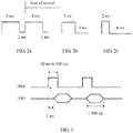
- the DCLS includes day, hour, minute, second, and control information. As shown in FIG. 1 , two consecutive broad pulses of 8 milliseconds (millisecond, ms) indicate a start of second. If elements are encoded at the second 8 ms, the elements are respectively element 0, element 1, element 2, ..., and element 99.
- a time format includes day, hour, minute, and second, and a time sequence is second-minute-hour-day. Occupied information bits are as follows: the second occupies 7 bits, the minute occupies 7 bits, the hour occupies 6 bits, and the day occupies 10 bits. Locations of the day, hour, minute, and second are between P0 to P5. P6 to P0 include other control information.
- Information about "second” includes element 1, element 2, element 3, element 4, element 6, element 7, and element 8; information about "minute” includes element 10, element 11, element 12, element 13, element 15, element 16, and element 17; and information about "hour” includes element 20, element 21, element 22, element 23, element 25, and element 26.
- Element 5, element 14, and element 24 are index markers with a width of 2 ms. All the hour, minute, and second are represented by using a BCD code (that is, a binary code of ten values from "0" to "9"). A low bit precedes a high bit, and a tens place follows a ones place.
- 1 second (second, s) is equally divided into 100 timeslots.
- Each timeslot includes 10 ms.
- a timeslot in which a high level lasts for 8 ms and a low level lasts for 2 ms identifies synchronization (as shown in FIG. 2a ); two consecutive synchronization signals identify a start of second; a timeslot in which a high level lasts for 5 ms and a low level lasts for 5 ms identifies a logical "1" (as shown in FIG. 2b ); and a timeslot in which a high level lasts for 2 ms and a low level lasts for 8 ms identifies a logical "0" (as shown in FIG. 2c ).
- FIG. 3 shows a schematic diagram of a TOD transmission method in the prior art.
- a baud rate is 9600 by default; no parity check is performed; one start bit (which is indicated by using a low level) and one stop bit (which is indicated by using a high level) are used; an idle frame is indicated by using a high level; there are eight data bits; and transmission of the TOD should start after a 1PPS rises by 1 ms and should be completed within 500 ms.
- the TOD indicates a time at which the current 1PPS triggers a rising edge.
- a sending frequency of a TOD protocol packet is once per second.
- the 1PPS and the TOD are transmitted in an RS422 level manner.
- a used physical connector is an RJ45 connector or a DB9 connector, and electrical characteristics of the physical connector meet a corresponding standard requirement.
- a line order requirement is shown in Table 1.
- FIG. 4 shows a schematic diagram of a TOD transmission scheme in the prior art.
- a grandmaster (Grandmaster, GM) clock and a device 1 implement time synchronization by using the Synchronous Ethernet (Synchronous Ethernet, SyncE) and the Precision Time Protocol (Precision Time Protocol, PTP), that is, by carrying a TOD by using a frame spacing of an Ethernet frame.
- the frame spacing may be included in an Ethernet data stream.
- the Ethernet data stream may be a Gigabit Ethernet (Gigabit Ethernet, GE) data stream.
- a first device may perform time synchronization by using a service interface, and the service interface supports a time synchronization function defined in the IEEE 1588-2008 formulated by the Institute of Electrical and Electronics Engineers (Institute for Electrical and Electronic Engineers, IEEE).
- An extra service interface needs to be occupied when the service interface supports the time synchronization function in the IEEE 1588-2008.
- a dedicated XFP/SFP module interface needs to be developed, so that the service interface supports the time synchronization in the IEEE 1588-2008, and costs are relatively high.
- the device 1 and the device 2 implement time synchronization by using eight lines in Table 1.
- Two lines are connected to ground (Ground, GND), default states of two lines are non-connected (NC), and four lines in two groups are used to send the TOD by using a 1PPS and a TOD.
- Sending of a TOD signal and sending of a 1PPS signal are separately implemented by means of differential transmission, that is, the TOD signal and the 1PPS signal each occupy two lines. Therefore, transmission of the TOD signal and the 1PPS signal occupies all of the four lines, so that the TOD can be transmitted only unidirectionally, that is, each device may only receive the TOD or send the TOD at a time.
- a dedicated 2 megabits per second (megabit per second, Mbps) external clock (Clock, CLK) interface is required between the device 1 and the device 2 to transmit clock frequency information, and the clock frequency information is used for frequency synchronization between network elements.
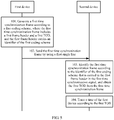
- FIG. 5 shows a flowchart of interaction in a time synchronization method according to an embodiment of this application.
- a first device generates a first time synchronization frame according to a first coding scheme, where the first time synchronization frame includes a first frame header and a first time of day TOD, the first frame header carries an identifier of the first coding scheme, and the first coding scheme defines a boundary of the first time synchronization frame and a location of the first TOD in the first time synchronization frame.
- the first device may obtain time information from a grandmaster clock according to a frame spacing of an Ethernet frame, or the first device is the grandmaster clock (for example, a BITS) and is configured to provide a timing service for another device, so that the first device may determine a current time of day TOD.
- the first device generates the first time synchronization frame according to the first coding scheme, where the first time synchronization frame carries first frame header information and the first TOD, the first frame header information carries an identifier of the first coding scheme, and the first coding scheme defines a boundary of the first time synchronization frame and the location of the first TOD in the first time synchronization frame.
- some commonly used software programs are further required to generate the first time synchronization frame. This is not limited in this application.
- the identifier of the first coding scheme may indicate an internal structure of the first time synchronization frame, a length of an occupied field, a specific frame header location and frame trailer location (represented as the boundary of the first time synchronization frame), content corresponding to different fields (that is, a field that is in the first time synchronization frame and that indicates the first TOD may be learned), and the like.
- the first coding scheme defines that the first time synchronization frame includes 100 timeslots; one bit is transmitted every 31.25 ⁇ s, and 10 bits may be transmitted in a time length of one timeslot, that is, one timeslot is 312.5 ⁇ s; and when a duty cycle of a high level is 75%, it indicates a start time for sending a time synchronization frame (as shown in FIG. 6 ), and the like. That is, a second device may identify the first time synchronization frame according to the identifier of the first coding scheme, and may learn the location of the TOD from the first time synchronization frame, and further obtain the first TOD.
- the first coding scheme may be determined according to the DCLS protocol.
- the DCLS carries element information by using a direct current bit, and the DCLS is transmitted by using a digital path without limitation of a transmission distance.
- the DCLS identifies a start of second by using two consecutive synchronization signals. Each timeslot is 10 ms, and one bit is transmitted in one timeslot.
- this application imposes no limitation on a quantity of timeslots that form the first time synchronization frame, a quantity of bits that can be transmitted in each timeslot, content corresponding to each bit, and the like.
- the first device may be any network device that can meet the foregoing proprietary protocol, such as a wavelength division device, a satellite positioning system receiver, a core network device, an aggregation network device, a base station, a base station controller, a server, an optical transport network device, a packet transport network device, or a switch. This is not limited in this application.
- the grandmaster clock may be any device that is used to provide a timing service, such as a satellite, a satellite positioning system receiver, a wavelength division device, a core network device, an aggregation network device, a base station, a base station controller, a server, or a switch. This is not limited in this application.
- the satellite positioning system receiver provides a timing service by successively using a wavelength division device, a router, a base station, and the like; or the satellite positioning system receiver provides a timing service by successively using a wavelength division device, a router, a base station, a router, a base station, and the like.
- the first time synchronization frame may convert 0, 1, 2, 3, ..., 9 that are used to indicate year, month, day, hour, minute, and second in the time information to binary-coded signals ("0" and "1") for representation. For example, when a duty cycle of a high level is 25%, it indicates “1"; and when a duty cycle of a high level is 50%, it indicates "0" (as shown in FIG. 6 ).
- Data transmission content in each timeslot is shown in the following Table 2.
- An undefined idle timeslot may be made readable and writable by software, so that a function may be expanded in the future.
- Table 2 Timeslot number Function description Bit width Remarks Filling module ts 1 Used for sending a frame sequence number. The frame sequence number increases by 1 for each frame. The value of the frame sequence number ranges from 0 to 255. Frame sequence numbers are numbered from 0 to 255 again after 255 frames are sent. 1 byte Value range: 0 to 255 Logic ts 2 ⁇ ts 11 Used for sending a PTP time corresponding to a frame header.
- the logic automatic all y sends a value configured by software ts 39 Used for sending a cascade port number.
- the logic automatic all y sends a value configured by software ts 40
- the logic automatic all y sends a value configured by software ts 41 N/A N/A N/A N/A N/A ⁇ ⁇ ⁇ ⁇ ⁇ ts 99 ⁇ ts 100
- a cyclic redundancy check code Cyclic Redundancy Check, CRC
- CRC Cyclic Redundancy Check
- the PTP time occupies a bit width of 10 bytes and is used to indicate year, month, day, hour, minute, and second in the time information.
- the SSM byte is used to indicate a quality level of a signal in a time synchronization process.
- the first time synchronization frame further carries a first time source identifier.
- the first time synchronization frame may carry the first time source identifier of the first device, for example, identity (Identity, ID) information.
- the first time synchronization frame may further include priority information of the first device, or may further include other information. This is not limited in this application.
- a time source identifier is carried in a time synchronization frame. In large-scale networking, a time source may still be accurately obtained. This reduces costs for repairing a line, and improves reliability.
- the first device sends the first time synchronization frame to a second device by using a first single line, so as to trigger the second device to identify the first time synchronization frame according to the identifier of the first coding scheme, obtain the first TOD from the first time synchronization frame, and trace a time of the first device according to the first TOD.
- the first device sends the first time synchronization frame to the second device by using a single line.
- the first time synchronization frame includes the first TOD and the first frame header, or may further include a time source identifier, frequency information, and the like. This is not limited in this application. This avoids a problem in the prior art that a separate line is required to send a 1PPS, thereby reducing a waste of line resources for sending a TOD.
- the single line mentioned in this application is a line used to transmit a serial signal.
- the single line may be implemented by using a pin (PIN) of an RJ45 connector.
- PIN pin
- the RJ45 connector includes eight pins. Each of the eight pins may be used to transmit one serial signal.
- the eight pins as a whole transmit a parallel signal including eight serial signals. Therefore, the eight pins of the RJ45 connector may be lines used to transmit a parallel signal.
- a device A traces a time of a device B means that the device A uses the device B as a grandmaster clock of the device A, so as to calibrate a clock time in the device A.
- the first time synchronization frame further carries first frequency information
- the first frequency information is further used to trigger the second device to trace the time of the first device according to the first frequency information.
- the first time synchronization frame further includes the first frequency information.
- the second device traces the time of the first device according to the first frequency information. For example, one bit (bit) is transmitted every 31.25 microseconds (microsecond, ⁇ s), that is, a frequency is 32 KHz. In this way, the first device does not need to add extra deployment of a 2 Mbps external clock interface or a line. This reduces engineering deployment, and reduces a waste of line resources.
- an interface that is used to transmit a 1PPS and a TOD in the prior art may be referred to as an "enhanced time interface". This is not limited in this application.
- the second device identifies the first time synchronization frame, and obtains the first TOD from the first time synchronization frame.
- the second device receives the first time synchronization frame sent by the first device, where the first time synchronization frame includes the first frame header and the first time of day TOD, the first frame header carries the identifier of the first coding scheme, and the first coding scheme defines the boundary of the first time synchronization frame and the location of the first TOD in the first time synchronization frame.
- the second device parses the time synchronization frame according to the first coding scheme. In this way, the second device can obtain the first time synchronization frame, and obtain the first TOD from the first time synchronization frame, so that the second device can trace the time of the first device according to the first TOD.
- the second device traces the time of the first device according to the identified first TOD.
- the second device may keep more precise time synchronization with the first device according to the first TOD and the frequency information in the first time synchronization frame in the embodiment of this application.
- the second device further needs to perform phase synchronization.
- this application imposes no limitation on a manner of phase synchronization.
- the method further includes: receiving, by the first device, a second time synchronization frame from a third device by using a second single line, where the second time synchronization frame is generated by the third device according to a second coding scheme, the second time synchronization frame includes a second TOD and a second frame header, the second frame header carries an identifier of the second coding scheme, and the second coding scheme defines a boundary of the second time synchronization frame and a location of the second TOD in the second time synchronization frame; identifying, by the first device, the second time synchronization frame according to the identifier of the second coding scheme, and obtaining the second TOD from the second time synchronization frame; and tracing, by the first device, a time of the third device according to the second TOD.
- a manner of generating the second time synchronization frame is the same as that of generating the first time synchronization frame.
- the second time synchronization frame includes the second TOD and the second frame header, the second frame header carries the identifier of the second coding scheme, and the second coding scheme defines the boundary of the second time synchronization frame and the location of the second TOD in the second time synchronization frame.
- the first device keeps time synchronization with the third device, and a specific process is the same as the process in which the second device keeps time synchronization with the first device. To avoid repetition, details are not described herein again.
- the first device may receive and send a time synchronization frame simultaneously (that is, receiving and sending the TOD simultaneously), that is, the first device may trace the time of the third device, and the second device may trace the time of the first device, so that multiple devices may keep time synchronization with each other.
- first time synchronization frame and the second time synchronization frame may be completely the same, or partially different (for example, only coding schemes are the same, but TOD content or frame header content is different), or completely different. This is not limited in this application.
- the method further includes: receiving, by the first device, a second time synchronization frame from a third device by using a second single line, where the second time synchronization frame is generated by the third device according to a second coding scheme, the second time synchronization frame includes a second TOD and a second frame header, the second frame header carries an identifier of the second coding scheme, and the second coding scheme defines a boundary of the second time synchronization frame and a location of the second TOD in the second time synchronization frame; identifying, by the first device, the second time synchronization frame according to the identifier of the second coding scheme, and obtaining the second TOD from the second time synchronization frame; determining, by the first device, a delay for transmitting the second time synchronization frame from the first device to the third device; correcting, by the first device, the second TOD according to the delay; and tracing, by the first device, a time of the third device according to the corrected second TOD.
- the first device may receive the second time synchronization frame sent, by the third device, over the second single line.
- a manner of generating the second time synchronization frame is the same as that of generating the first time synchronization frame.
- the second time synchronization frame includes the second TOD and the second frame header, the second frame header carries the identifier of the second coding scheme, and the second coding scheme defines the boundary of the second time synchronization frame and the location of the second TOD in the second time synchronization frame.
- the first device obtains the second TOD from the third device.
- the first device is not consistent with the second TOD.
- the first device further needs to determine the delay for transmitting the second time synchronization frame from the first device to the third device, and trace the time of the third device according to the second TOD and the delay.
- time information of the first device may be manually measured and corrected, so that the first device keeps time synchronization with the third device. This is not limited in this application.
- the second time synchronization frame further carries second frequency information; and that the first device traces a time of the third device according to the corrected second TOD includes: tracing, by the first device, the time of the third device according to the corrected second TOD and the second frequency information.
- the second time synchronization frame may further carry the second frequency information, so that the first device traces the time of the third device according to the frequency information and the corrected time information. In this way, the first device does not need to add extra deployment of a 2 Mbps external clock interface or a line. This reduces engineering deployment, and reduces a waste of line resources.
- that the first device determines a delay for transmitting the second time synchronization frame from the first device to the third device includes: sending, by the first device at a first time, the second time synchronization frame to the third device by using the second single line; receiving, by the first device at a second time, the second time synchronization frame returned by the third device; and determining, by the first device, that the delay for transmitting the second time synchronization frame from the first device to the third device is equal to half of a difference between the second time and the first time.
- the first device may perform automatic delay measurement.
- FIG. 7 shows a schematic diagram of performing automatic delay measurement by the first device. With the automatic delay measurement of the first device, manual delay measurement is avoided, so that engineering deployment is reduced.
- a subrack A (that is, a function module of the first device) sends the second time synchronization frame to a subrack B (that is, a function module of the third device).
- a local PTP timestamp t1 (that is, a first time) is added to a time for sending the second time synchronization frame.
- a corresponding port of the subrack B is configured with a delay measurement mode.
- the subrack B When receiving the second time synchronization frame, the subrack B directly performs outloop on the received second time synchronization frame, and returns the second time synchronization frame to the subrack A.
- the subrack A adds a local PTP timestamp t2 (that is, a second time) to a time for receiving the returned second time synchronization frame.
- the subrack A when receiving the returned second time synchronization frame, the subrack A needs to determine whether the received frame is the second time synchronization frame sent by the subrack A, so as to ensure that a frame sequence number is correct. This avoids an error that is caused because a delay calculation is performed on a sending time and a receiving time that are of different frames.
- the subrack A may determine, according to a subrack number, a port number, or the like, whether the received frame is the second time synchronization frame sent by the subrack A. This is not limited in this application.
- the first device may calculate a unidirectional path delay according to a first time for sending the second time synchronization frame and a second time for receiving the returned second time synchronization frame. Specifically, the delay is (t 2 - t 1 )/2, and the subrack A saves the delay.
- the first device corrects, according to the determined delay and first time information, time information based on the first time information, so that a time of the first device is consistent with a time of the third device, that is, the first device keeps time synchronization with the third device.
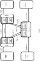
- the time synchronization method may be applied to a ring protection scenario, as shown in FIG. 8 .
- a device 1, a device 2, and a device 3 are co-site devices.
- the device 1 keeps time synchronization with the grandmaster clock, and then sends a first time synchronization frame to the device 2 and device 3 by using an interface, so that the device 2 keeps time synchronization with the device 1, and the device 3 keeps time synchronization with the device 1.
- the device 3 (which may be considered as a first device) may further send a second time synchronization frame to the device 2, so that the device 2 keeps time synchronization with the device 3. That is, the device 3 can receive a time synchronization frame (for example, TOD_RX in FIG. 8 ) from the device 1, and can send a time synchronization frame (for example, TOD_TX in FIG. 8 ) to the device 2.
- a time synchronization frame for example, TOD_RX in FIG. 8
- TOD_TX time synchronization frame
- a second device may also automatically detect a delay between the second device and the first device, and a specific process is the same as the process in which the first device automatically detects a delay between the first device and a third device. To avoid repetition, details are not described herein again.
- first time synchronization frame and the second time synchronization frame may be the same, or may be different; and a first TOD and a second TOD may be the same, or may be different. This is not limited in this application.
- the third device sends the second time synchronization frame to the first device, so that the first device synchronizes with the third device; and then the first device immediately sends the first time synchronization frame to the second device, so that the second device synchronizes with the first device. Therefore, theoretically, a TOD in the first time synchronization frame and a TOD in the second time synchronization frame are the same; however, there is an error in an actual situation, and the error is generally less than 100 nanoseconds.
- the third device and the second device may be a same device.
- a secondary clock keeps time synchronization with the device 3.
- the device 3 may send a time synchronization frame to the device 1, so that the device 1 keeps time synchronization with the device 3.
- a time synchronization frame is generated according to time information, so that bidirectional transmission between devices and time synchronization between different devices may be implemented.
- a transmission direction may be determined according to a device priority, so as to fully use idle line resources, and the device priority may be determined according to a distance between a device and a time source. This is not limited in this application.
- a first device generates, according to a first coding scheme, a first time synchronization frame including a first TOD and a first frame header, where the first frame header carries an identifier of the first coding scheme, and the first coding scheme defines a boundary of the first time synchronization frame and a location of the first TOD in the first time synchronization frame; and sends the first time synchronization frame to a second device by using a single line, so that the second device identifies the first time synchronization frame according to the identifier of the first coding scheme, obtains the first TOD from the first time synchronization frame, and traces a time of the first device according to the first TOD, thereby saving line resources and implementing bidirectional transmission of time information between devices.
- sequence numbers of the foregoing processes do not mean execution sequences in various embodiments of this application.
- the execution sequences of the processes should be determined according to functions and internal logic of the processes, and should not be construed as any limitation on the implementation processes of the embodiments of this application.
- a first device generates a first time synchronization frame according to a first coding scheme, where the first time synchronization frame includes a first frame header and a first TOD, and the first frame header carries an identifier of the first coding scheme.
- the first device may obtain a TOD from a grandmaster clock according to a service flow and the like, or the first device is the grandmaster clock and is configured to provide a timing service for another device, so that the first device may generate the first time synchronization frame.
- the first device sends the first time synchronization frame to a second device by using a single line.
- the second device identifies the first time synchronization frame according to the identifier of the first coding scheme that is carried in the first frame header, and obtains the first TOD from the first time synchronization frame.
- the second device sends the first time synchronization frame to the first device at a time 1.
- the first device may perform automatic delay measurement.
- a measurement signal carries measurement information and measurement signal header information, and the measurement signal header information is used to indicate a coding scheme of the measurement signal.
- the second device receives the returned first time synchronization frame at a time 2.
- the second device determines half of a difference between the time 2 and the time 1 as a delay 1 between the second device and the first device.
- the second device keeps time synchronization with the first device according to the delay 1 and the first TOD.
- a third device generates a second time synchronization frame according to a second coding scheme, where the second time synchronization frame includes a second frame header and a second TOD, and the second frame header carries an identifier of the second coding scheme.
- the third device sends the second time synchronization frame to the first device by using a single line.
- the first device identifies the second time synchronization frame according to the identifier of the second coding scheme that is carried in the second frame header, and obtains the second TOD from the second time synchronization frame.
- the first device sends the second time synchronization frame to the third device at a time 3.
- the first device receives, at a time 4, the second time synchronization frame returned by the third device.
- the first device When receiving the measurement signal, the first device needs to determine whether a received frame is a time synchronization frame sent by the first device, so as to ensure that a frame sequence number is correct. This avoids an error that is caused because a delay calculation is performed on a sending time and a receiving time that are of different frames.
- the first device determines half of a difference between the time 4 and the time 3 as a delay 2 between the first device and the third device.
- the first device keeps time synchronization with the third device according to the delay 2 and the second TOD.
- the first device may generate the first time synchronization frame according to the first coding scheme, and send the first time synchronization frame to the second device, so as to keep time synchronization with the second device.
- the first device may further receive the second time synchronization frame that is generated by the third device according to the second coding scheme, so as to keep synchronization with the third device. That is, the first device may receive a TOD and send a TOD simultaneously, so that tracing and protection of multiple devices may be implemented.
- step 370 to step 420 and step 310 to step 360 may be performed simultaneously, that is, step 370 and step 310 may be performed simultaneously; or step 370 may be performed before step 310. This is not limited in this application.
- a first device generates, according to a first coding scheme, a first time synchronization frame including a first TOD and a first frame header, where the first frame header carries an identifier of the first coding scheme, and the first coding scheme defines a boundary of the first time synchronization frame and a location of the first TOD in the first time synchronization frame; and sends the first time synchronization frame to a second device by using a single line, so that the second device identifies the first time synchronization frame according to the identifier of the first coding scheme, obtains the first TOD from the first time synchronization frame, and traces a time of the first device according to the first TOD, thereby saving line resources and implementing bidirectional transmission of time information between devices.
- sequence numbers of the foregoing processes do not mean execution sequences in various embodiments of this application.
- the execution sequences of the processes should be determined according to functions and internal logic of the processes, and should not be construed as any limitation on the implementation processes of the embodiments of this application.
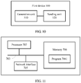
- FIG. 10 shows a schematic block diagram of a first device 500 according to an embodiment of this application.
- the first device 500 may be configured to execute the method shown in FIG. 5 .
- the first device 500 includes:
- the first device generates, according to a first coding scheme, a first time synchronization frame including a first TOD and a first frame header, where the first frame header carries an identifier of the first coding scheme, and the first coding scheme defines a boundary of the first time synchronization frame and a location of the first TOD in the first time synchronization frame; and sends the first time synchronization frame to a second device by using a single line, so that the second device identifies the first time synchronization frame according to the identifier of the first coding scheme, obtains the first TOD from the first time synchronization frame, and traces a time of the first device according to the first TOD, so as to save line resources.
- the first device 500 further includes:
- the first device 500 further includes:
- the determining unit is specifically configured to:
- first time information is represented in a binary-coded form.
- the first time synchronization frame further carries a first time source identifier.
- the second time synchronization frame further carries second frequency information
- the second tracing unit is specifically configured to: trace the time of the third device according to the corrected second TOD and the second frequency information.
- the second time synchronization frame further carries a second time source identifier.
- the second TOD is represented in a binary-coded form.
- the second device and the third device are a same device.
- the first time synchronization frame further carries first frequency information
- the first time synchronization frame is further used to trigger the second device to trace the time of the first device according to the first frequency information.
- the first device 500 in this embodiment of this application may be corresponding to a first device in a time synchronization method according to an embodiment of this application, and the foregoing and other operations and/or functions of units in the first device 500 are separately used to implement corresponding processes of the methods. For brevity, details are not described herein again.
- a first device provided in this embodiment of this application generates, according to a first coding scheme, a first time synchronization frame including a first TOD and a first frame header, where the first frame header carries an identifier of the first coding scheme, and the first coding scheme defines a boundary of the first time synchronization frame and a location of the first TOD in the first time synchronization frame; and sends the first time synchronization frame to a second device by using a single line, so that the second device identifies the first time synchronization frame according to the identifier of the first coding scheme, obtains the first TOD from the first time synchronization frame, and traces a time of the first device according to the first TOD, thereby saving line resources and implementing bidirectional transmission of time information between devices.
- FIG. 11 shows a structure of a first device according to an embodiment of this application.
- the first device shown in FIG. 11 may be configured to implement the first device 500 shown in FIG. 10 .
- the first device includes at least one processor 702 (for example, a CPU), at least one network interface 705 or another communications interface, a memory 706, and at least one communications bus 703 that is configured to implement connection and communication between these apparatuses.
- the processor 702 is configured to execute an executable module stored in the memory 706, for example, a computer program.
- the memory 706 may include a high-speed random access memory (RAM: Random Access Memory), and may also include a non-volatile memory (non-volatile memory), for example, at least one magnetic disk memory. Communication connection to at least one other network element is implemented by using the at least one network interface 705 (which may be wired or wireless).
- the memory 706 stores a program 7061, and the processor 702 executes the program 7061, so as to perform the following operations:
- a first time synchronization frame carrying a first TOD and first frame header information is generated, and the first time synchronization frame is sent to a second device by using a single line, so that the second device keeps time synchronization with the first device according to the first time synchronization frame, so as to save line resources.
- processor 702 is further configured to:
- processor 702 is further configured to:
- processor 702 is specifically configured to:
- first time information carried in the first time synchronization frame is represented in a binary-coded form.
- the first time synchronization frame further carries a first time source identifier.
- the second time synchronization frame further carries second frequency information
- the processor 702 is specifically configured to: trace the time of the third device according to the corrected second TOD and the second frequency information.
- the second device and the third device are a same device.
- the second time synchronization frame further carries a second time source identifier.
- the second TOD is represented in a binary-coded form.
- the first time synchronization frame further carries first frequency information
- the first time synchronization frame is further used to trigger the second device to trace the time of the first device according to the first frequency information.
- a first device generates, according to a first coding scheme, a first time synchronization frame including a first TOD and a first frame header, where the first frame header carries an identifier of the first coding scheme, and the first coding scheme defines a boundary of the first time synchronization frame and a location of the first TOD in the first time synchronization frame; and sends the first time synchronization frame to a second device by using a single line, so that the second device identifies the first time synchronization frame according to the identifier of the first coding scheme, obtains the first TOD from the first time synchronization frame, and traces a time of the first device according to the first TOD, thereby saving line resources and implementing bidirectional transmission of time information between devices.
- An embodiment of this application further provides a computer storage medium, and the computer storage medium may store a program instruction that is used to indicate any one of methods.
- the storage medium may be specifically a memory 706.
- sequence numbers of the foregoing processes do not mean execution sequences in various embodiments of this application.
- the execution sequences of the processes should be determined according to functions and internal logic of the processes, and should not be construed as any limitation on the implementation processes of the embodiments of this application.
- the disclosed system, apparatus, and method may be implemented in other manners.
- the described apparatus embodiment is merely an example.
- the unit division is merely logical function division and may be other division in actual implementation.
- multiple units or components may be combined or integrated into another system, or some features may be ignored or not performed.
- the displayed or discussed mutual couplings or direct couplings or communication connections may be implemented through some interfaces, indirect couplings or communication connections between the apparatuses or units, or electrical connections, mechanical connections, or connections in other forms.
- the units described as separate parts may or may not be physically separate, and parts displayed as units may or may not be physical units, may be located in one position, or may be distributed on multiple network units. Some or all of the units may be selected according to actual needs to achieve the objectives of the solutions of the embodiments.
- function units in the embodiments of this application may be integrated into one processing unit, or each of the units may exist alone physically, or two or more units are integrated into one unit.
- the integrated unit may be implemented in a form of hardware, or may be implemented in a form of a software function unit.
- the integrated unit When the integrated unit is implemented in the form of a software function unit and sold or used as an independent product, the integrated unit may be stored in a computer-readable storage medium. Based on such an understanding, the technical solutions of this application essentially, or the part contributing to the prior art, or some of the technical solutions may be implemented in a form of a software product.
- the software product is stored in a storage medium, and includes several instructions for instructing a computer device (which may be a personal computer, a server, or a network device) to perform all or some of the steps of the methods described in the embodiments of this application.
- the foregoing storage medium includes: any medium that can store program code, such as a USB flash drive, a removable hard disk, a read-only memory (ROM, Read-Only Memory), a random access memory (RAM, Random Access Memory), a magnetic disk, or an optical disc.
- program code such as a USB flash drive, a removable hard disk, a read-only memory (ROM, Read-Only Memory), a random access memory (RAM, Random Access Memory), a magnetic disk, or an optical disc.
Landscapes
- Engineering & Computer Science (AREA)
- Computer Networks & Wireless Communication (AREA)
- Signal Processing (AREA)
- Theoretical Computer Science (AREA)
- Computer Security & Cryptography (AREA)
- Physics & Mathematics (AREA)
- General Engineering & Computer Science (AREA)
- General Physics & Mathematics (AREA)
- Synchronisation In Digital Transmission Systems (AREA)
Claims (14)
- Zeitsynchronisationsverfahren, das Folgendes umfasst:Erzeugen (101),durch eine erste Vorrichtung, eines ersten Zeitsynchronisationsframes gemäß einem ersten Codierungsschema, wobei der erste Zeitsynchronisationsframe einen ersten Frame-Header und eine erste Tageszeit (time of day - TOD) umfasst, wobei der erste Frame-Header einen Identifikator des ersten Codierungsschemas trägt und das erste Codierungsschema eine Grenze des ersten Zeitsynchronisationsframes und eine Stelle der ersten TOD in dem ersten Zeitsynchronisationsframe definiert; undSenden (102),durch die erste Vorrichtung, des ersten Zeitsynchronisationsframes an eine zweite Vorrichtung unter Verwendung einer ersten einzelnen Leitung, um die zweite Vorrichtung dazu auszulösen, den ersten Zeitsynchronisationsframe gemäß dem Identifikator des ersten Codierungsschemas zu identifizieren (103), die erste TOD von dem ersten Zeitsynchronisationsframe zu erlangen und eine Zeit der ersten Vorrichtung gemäß der ersten TOD nachzuverfolgen (104).
- Verfahren nach Anspruch 1, wobei das Verfahren ferner Folgendes umfasst:Empfangen, durch die erste Vorrichtung, eines zweiten Zeitsynchronisationsframes von einer dritten Vorrichtung unter Verwendung einer zweiten einzelnen Leitung, wobei der zweite Zeitsynchronisationsframe durch die dritte Vorrichtung gemäß einem zweiten Codierungsschema erzeugt ist, wobei der zweite Zeitsynchronisationsframe eine zweite TOD und einen zweiten Frame-Header umfasst, wobei der zweite Frame-Header einen Identifikator des zweiten Codierungsschemas trägt und das zweite Codierungsschema eine Grenze des zweiten Zeitsynchronisationsframes und eine Stelle der zweiten TOD in dem zweiten Zeitsynchronisationsframe definiert;Identifizieren, durch die erste Vorrichtung, des zweiten Zeitsynchronisationsframes gemäß dem Identifikator des zweiten Codierungsschemas und Erlangen der zweiten TOD von dem zweiten Zeitsynchronisationsframe; undNachverfolgen, durch die erste Vorrichtung, einer Zeit der dritten Vorrichtung gemäß der zweiten TOD.
- Verfahren nach Anspruch 1, wobei das Verfahren ferner Folgendes umfasst:Empfangen, durch die erste Vorrichtung, eines zweiten Zeitsynchronisationsframes von einer dritten Vorrichtung unter Verwendung einer zweiten einzelnen Leitung, wobei der zweite Zeitsynchronisationsframe durch die dritte Vorrichtung gemäß einem zweiten Codierungsschema erzeugt ist, wobei der zweite Zeitsynchronisationsframe eine zweite TOD und einen zweiten Frame-Header umfasst, wobei der zweite Frame-Header einen Identifikator des zweiten Codierungsschemas trägt, und das zweite Codierungsschema eine Grenze des zweiten Zeitsynchronisationsframes und eine Stelle der zweiten TOD in dem zweiten Zeitsynchronisationsframe definiert;Identifizieren, durch die erste Vorrichtung, des zweiten Zeitsynchronisationsframes gemäß dem Identifikator des zweiten Codierungsschemas und Erlangen der zweiten TOD von dem zweiten Zeitsynchronisationsframe;Bestimmen, durch die erste Vorrichtung, einer Verzögerung zum Übertragen des zweiten Zeitsynchronisationsframes von der ersten Vorrichtung an die dritte Vorrichtung;Korrigieren, durch die erste Vorrichtung, der zweiten TOD gemäß der Verzögerung; undNachverfolgen, durch die erste Vorrichtung, einer Zeit der dritten Vorrichtung gemäß der korrigierten zweiten TOD.
- Verfahren nach Anspruch 3, wobei das Bestimmen, durch die erste Vorrichtung, einer Verzögerung zum Übertragen des zweiten Zeitsynchronisationsframes von der ersten Vorrichtung an die dritte Vorrichtung Folgendes umfasst:Senden, durch die erste Vorrichtung zu einer ersten Zeit, des zweiten Zeitsynchronisationsframes an die dritte Vorrichtung unter Verwendung der zweiten einzelnen Leitung;Empfangen, durch die erste Vorrichtung zu einer zweiten Zeit, des zweiten Zeitsynchronisationsframes, der durch die dritte Vorrichtung zurückgesendet ist; undBestimmen, durch die erste Vorrichtung, dass die Verzögerung zum Übertragen des zweiten Zeitsynchronisationsframes von der ersten Vorrichtung an die dritte Vorrichtung gleich der Hälfte einer Differenz zwischen der zweiten Zeit und der ersten Zeit ist.
- Verfahren nach Anspruch 3 oder 4, wobei der zweite Zeitsynchronisationsframe ferner eine zweite Frequenzinformation trägt und das Nachverfolgen, durch die erste Vorrichtung, einer Zeit der dritten Vorrichtung gemäß der korrigierten zweiten TOD Folgendes umfasst:
Nachverfolgen, durch die erste Vorrichtung, der Zeit der dritten Vorrichtung gemäß der korrigierten zweiten TOD und der zweiten Frequenzinformation. - Verfahren nach einem der Ansprüche 2 bis 5, wobei die zweite Vorrichtung und die dritte Vorrichtung eine selbe Vorrichtung sind.
- Verfahren nach einem der Ansprüche 1 bis 6, wobei der erste Zeitsynchronisationsframe ferner die erste Frequenzinformation trägt und der erste Zeitsynchronisationsframe ferner dazu verwendet wird, die zweite Vorrichtung dazu auszulösen, die Zeit der ersten Vorrichtung gemäß der ersten Frequenzinformation nachzuverfolgen.
- Erste Vorrichtung (500), die Folgendes umfasst:eine Erzeugungseinheit (510), die dazu konfiguriert ist, einen ersten Zeitsynchronisationsframe gemäß einem ersten Codierungsschema zu erzeugen, wobei der erste Zeitsynchronisationsframe einen ersten Frame-Header und eine erste Tageszeit, TOD, umfasst, wobei der erste Frame-Header einen Identifikator des ersten Codierungsschemas trägt und das erste Codierungsschema eine Grenze des ersten Zeitsynchronisationsframes und eine Stelle der ersten TOD in dem ersten Zeitsynchronisationsframe definiert; undeine Sendeeinheit (250), die dazu konfiguriert ist, den ersten Zeitsynchronisationsframe, der durch die Erzeugungseinheit erzeugt ist, unter Verwendung einer ersten einzelnen Leitung an eine zweite Vorrichtung zu senden, um die zweite Vorrichtung dazu auszulösen, den ersten Zeitsynchronisationsframe gemäß dem Identifikator des ersten Codierungsschemas zu identifizieren, die erste TOD von dem ersten Zeitsynchronisationsframe zu erlangen und eine Zeit der ersten Vorrichtung gemäß der ersten TOD nachzuverfolgen.
- Erste Vorrichtung nach Anspruch 8, wobei die erste Vorrichtung ferner Folgendes umfasst:eine erste Empfangseinheit, die dazu konfiguriert ist, einen zweiten Zeitsynchronisationsframe von einer dritten Vorrichtung unter Verwendung einer zweiten einzelnen Leitung zu empfangen, wobei der zweite Zeitsynchronisationsframe durch die dritte Vorrichtung gemäß einem zweiten Codierungsschema erzeugt ist, wobei der zweite Zeitsynchronisationsframe eine zweiten TOD und einen zweiten Frame-Header umfasst, wobei der zweite Frame-Header einen Identifikator des zweiten Codierungsschemas trägt und das zweite Codierungsschema eine Grenze des zweiten Zeitsynchronisationsframes und eine Stelle der zweiten TOD in dem zweiten Zeitsynchronisationsframe definiert;eine erste Identifizierungseinheit, die dazu konfiguriert ist, den zweiten Zeitsynchronisationsframe gemäß dem Identifikator des zweiten Codierungsschemas zu identifizieren und die zweite TOD von dem zweiten Zeitsynchronisationsframe zu erlangen; undeine erste Nachverfolgungseinheit, die dazu konfiguriert ist, eine Zeit der dritten Vorrichtung gemäß der zweiten TOD nachzuverfolgen.
- Erste Vorrichtung nach Anspruch 8, wobei die erste Vorrichtung ferner Folgendes umfasst:eine zweite Empfangseinheit, die dazu konfiguriert ist, einen zweiten Zeitsynchronisationsframe von einer dritten Vorrichtung unter Verwendung einer zweiten einzelnen Leitung zu empfangen, wobei der zweite Zeitsynchronisationsframe durch die dritte Vorrichtung gemäß einem zweiten Codierungsschema erzeugt ist, wobei der zweite Zeitsynchronisationsframe eine zweite TOD und einen zweiten Frame-Header umfasst, wobei der zweite Frame-Header einen Identifikator des zweiten Codierungsschemas trägt und das zweite Codierungsschema eine Grenze des zweiten Zeitsynchronisationsframes und eine Stelle der zweiten TOD in dem zweiten Zeitsynchronisationsframe definiert;eine zweite Identifizierungseinheit, die dazu konfiguriert ist, den zweiten Zeitsynchronisationsframe gemäß dem Identifikator des zweiten Codierungsschemas zu identifizieren und die zweite TOD von dem zweiten Zeitsynchronisationsframe zu erlangen;eine Bestimmungseinheit, die dazu konfiguriert ist, eine Verzögerung zum Übermitteln des zweiten Zeitsynchronisationsframes von der ersten Vorrichtung zu der dritten Vorrichtung zu bestimmen;eine Korrektureinheit, die dazu konfiguriert ist, die zweite TOD gemäß der Verzögerung zu korrigieren; undeine zweite Nachverfolgungseinheit, die dazu konfiguriert ist, eine Zeit der dritten Vorrichtung gemäß der korrigierten zweiten TOD nachzuverfolgen.
- Erste Vorrichtung nach Anspruch 10, wobei die Bestimmungseinheit zu Folgendem konfiguriert ist:Senden, zu einer ersten Zeit, des zweiten Zeitsynchronisationsframes an die dritte Vorrichtung unter Verwendung der zweiten einzelnen Leitung;Empfangen, zu einer zweiten Zeit, des zweiten Zeitsynchronisationsframes, der durch die dritte Vorrichtung zurückgesendet ist; undBestimmen, dass die Verzögerung zum Übertragen des zweiten Zeitsynchronisationsframes von der ersten Vorrichtung an die dritte Vorrichtung gleich einer Hälfte einer Differenz zwischen der zweiten Zeit und der ersten Zeit ist.
- Erste Vorrichtung nach Anspruch 10 oder 11, wobei der zweite Zeitsynchronisationsframe ferner eine zweite Frequenzinformation trägt, und die zweite Nachverfolgungseinheit konkret zu Folgendem konfiguriert ist:
Nachverfolgen der Zeit der dritten Vorrichtung gemäß der korrigierten zweiten TOD und der zweiten Frequenzinformation. - Erste Vorrichtung nach einem der Ansprüche 9 bis 12, wobei die zweite Vorrichtung und die dritte Vorrichtung eine selbe Vorrichtung sind.
- Erste Vorrichtung nach einem der Ansprüche 8 bis 13, wobei der erste Zeitsynchronisationsframe ferner eine erste Frequenzinformation trägt und der erste Zeitsynchronisationsframe ferner dazu verwendet wird, die zweite Vorrichtung dazu auszulösen, die Zeit der ersten Vorrichtung gemäß der ersten Frequenzinformation nachzuverfolgen.
Priority Applications (1)
| Application Number | Priority Date | Filing Date | Title |
|---|---|---|---|
| EP20192996.5A EP3806356B1 (de) | 2016-08-10 | 2016-08-10 | Zeitsynchronisationsverfahren und -vorrichtung |
Applications Claiming Priority (1)
| Application Number | Priority Date | Filing Date | Title |
|---|---|---|---|
| PCT/CN2016/094456 WO2018027704A1 (zh) | 2016-08-10 | 2016-08-10 | 时间同步的方法和设备 |
Related Child Applications (2)
| Application Number | Title | Priority Date | Filing Date |
|---|---|---|---|
| EP20192996.5A Division-Into EP3806356B1 (de) | 2016-08-10 | 2016-08-10 | Zeitsynchronisationsverfahren und -vorrichtung |
| EP20192996.5A Division EP3806356B1 (de) | 2016-08-10 | 2016-08-10 | Zeitsynchronisationsverfahren und -vorrichtung |
Publications (3)
| Publication Number | Publication Date |
|---|---|
| EP3480997A1 EP3480997A1 (de) | 2019-05-08 |
| EP3480997A4 EP3480997A4 (de) | 2019-08-14 |
| EP3480997B1 true EP3480997B1 (de) | 2020-10-14 |
Family
ID=61161494
Family Applications (2)
| Application Number | Title | Priority Date | Filing Date |
|---|---|---|---|
| EP16912159.7A Not-in-force EP3480997B1 (de) | 2016-08-10 | 2016-08-10 | Zeitsynchronisationsverfahren und -vorrichtung |
| EP20192996.5A Active EP3806356B1 (de) | 2016-08-10 | 2016-08-10 | Zeitsynchronisationsverfahren und -vorrichtung |
Family Applications After (1)
| Application Number | Title | Priority Date | Filing Date |
|---|---|---|---|
| EP20192996.5A Active EP3806356B1 (de) | 2016-08-10 | 2016-08-10 | Zeitsynchronisationsverfahren und -vorrichtung |
Country Status (5)
| Country | Link |
|---|---|
| US (2) | US10855387B2 (de) |
| EP (2) | EP3480997B1 (de) |
| CN (2) | CN112187390B (de) |
| ES (1) | ES2831381T3 (de) |
| WO (1) | WO2018027704A1 (de) |
Families Citing this family (10)
| Publication number | Priority date | Publication date | Assignee | Title |
|---|---|---|---|---|
| ES2831381T3 (es) * | 2016-08-10 | 2021-06-08 | Huawei Tech Co Ltd | Procedimiento y dispositivo de sincronización de tiempo |
| JP2021044629A (ja) * | 2019-09-06 | 2021-03-18 | 株式会社東芝 | ネットワークシステム、送信装置及び受信装置 |
| US10867462B1 (en) | 2020-03-18 | 2020-12-15 | B/E Aerospace, Inc. | Self-vending beverage distribution station |
| CN111478745A (zh) * | 2020-04-09 | 2020-07-31 | 浙江赛思电子科技有限公司 | 时钟时间传递协议装置及其协议方法 |
| US11564185B2 (en) | 2020-04-17 | 2023-01-24 | Rockwell Collins, Inc. | Precise time synchronization for 4G automatic link establishment (ALE) stations |
| WO2021240606A1 (ja) * | 2020-05-25 | 2021-12-02 | 日本電信電話株式会社 | 送信装置、受信装置、送信方法及び送受信システム |
| CN114430302B (zh) * | 2020-10-29 | 2025-05-06 | 南京中兴新软件有限责任公司 | 时间同步方法及装置 |
| CN115643607A (zh) * | 2022-09-30 | 2023-01-24 | 重庆御芯微信息技术有限公司 | 广域无线物联网通信的异步数据发送和接收方法 |
| US12432001B2 (en) * | 2023-01-31 | 2025-09-30 | Ufi Space Co., Ltd. | Distributed synchronization system |
| US12556357B2 (en) | 2024-03-21 | 2026-02-17 | International Business Machines Corporation | Flexible synchronization of time-of-day components |
Family Cites Families (12)
| Publication number | Priority date | Publication date | Assignee | Title |
|---|---|---|---|---|
| CN101390294B (zh) * | 2005-05-10 | 2012-05-30 | 高通股份有限公司 | 使用多通信模式用户设备使基站同步 |
| CN101222281B (zh) * | 2008-01-31 | 2010-10-13 | 北京创毅视讯科技有限公司 | 移动多媒体广播中的单频网系统及其同步系统和同步方法 |
| US8775849B2 (en) * | 2010-05-10 | 2014-07-08 | Ikanos Communications, Inc. | Systems and methods for transporting time-of-day information in a communication system |
| CN101873187A (zh) * | 2010-05-25 | 2010-10-27 | 中兴通讯股份有限公司 | 时钟同步方法及系统 |
| US8670439B2 (en) * | 2010-07-02 | 2014-03-11 | Futurewei Technologies, Inc. | Method for accurate distribution of time to a receiver node in an access network |
| JP5569299B2 (ja) * | 2010-09-28 | 2014-08-13 | 富士通株式会社 | 通信システム及び通信インタフェース装置、並びに同期方法 |
| CN102355281B (zh) * | 2011-06-30 | 2013-11-13 | 桂林电子科技大学 | 混合跳频无线收发系统及其运行方法 |
| JP2014135657A (ja) * | 2013-01-10 | 2014-07-24 | Sumitomo Electric Ind Ltd | 同期維持装置、局側装置、宅側装置、通信システム及び同期時刻の維持方法 |
| CN103346873B (zh) * | 2013-06-27 | 2016-08-10 | 华为技术有限公司 | 一种时间同步的方法和设备 |
| CN103401672B (zh) * | 2013-07-24 | 2016-08-24 | 福建星网锐捷网络有限公司 | 时间同步装置、设备及系统 |
| CN104601268B (zh) * | 2014-12-25 | 2017-07-25 | 大唐电信(成都)信息技术有限公司 | 一种基于irig‑b的时频同步状态信息编码格式及编码方法 |
| ES2831381T3 (es) * | 2016-08-10 | 2021-06-08 | Huawei Tech Co Ltd | Procedimiento y dispositivo de sincronización de tiempo |
-
2016
- 2016-08-10 ES ES16912159T patent/ES2831381T3/es active Active
- 2016-08-10 CN CN202010887431.XA patent/CN112187390B/zh not_active Expired - Fee Related
- 2016-08-10 CN CN201680088120.9A patent/CN109644120B/zh not_active Expired - Fee Related
- 2016-08-10 EP EP16912159.7A patent/EP3480997B1/de not_active Not-in-force
- 2016-08-10 EP EP20192996.5A patent/EP3806356B1/de active Active
- 2016-08-10 WO PCT/CN2016/094456 patent/WO2018027704A1/zh not_active Ceased
-
2019
- 2019-01-28 US US16/259,142 patent/US10855387B2/en not_active Expired - Fee Related
-
2020
- 2020-09-01 US US17/008,924 patent/US11228387B2/en not_active Expired - Fee Related
Non-Patent Citations (1)
| Title |
|---|
| None * |
Also Published As
| Publication number | Publication date |
|---|---|
| ES2831381T3 (es) | 2021-06-08 |
| WO2018027704A1 (zh) | 2018-02-15 |
| CN109644120A (zh) | 2019-04-16 |
| CN112187390B (zh) | 2022-02-11 |
| US20200403720A1 (en) | 2020-12-24 |
| CN109644120B (zh) | 2020-10-09 |
| CN112187390A (zh) | 2021-01-05 |
| US11228387B2 (en) | 2022-01-18 |
| US10855387B2 (en) | 2020-12-01 |
| US20190158204A1 (en) | 2019-05-23 |
| EP3806356A1 (de) | 2021-04-14 |
| EP3480997A4 (de) | 2019-08-14 |
| EP3480997A1 (de) | 2019-05-08 |
| EP3806356B1 (de) | 2023-06-14 |
Similar Documents
| Publication | Publication Date | Title |
|---|---|---|
| US11228387B2 (en) | Time synchronization method and device | |
| US10673565B2 (en) | Confirming data accuracy in a distributed control system | |
| US20210392065A1 (en) | Receive-side timestamp accuracy | |
| EP2959600B1 (de) | Zeitsynchroner einsteckbarer sender/empfänger | |
| US11876884B2 (en) | Communication method and optical module | |
| EP3149897B1 (de) | Hochgeschwindigkeitsprotokoll für ein verteiltes steuerungssystem | |
| CN101877633B (zh) | 信号同步的方法和系统、及信号接收装置和信号发送装置 | |
| US20150055644A1 (en) | Precise timestamping of ethernet packets by compensating for start-of-frame delimiter detection delay and delay variations | |
| EP3809636B1 (de) | Zeitverzögerungsmessverfahren und netzwerkvorrichtung | |
| EP2941006A1 (de) | Verfahren und system für taktreferenzströme | |
| CN114172604A (zh) | 时延补偿方法、装置、设备及计算机可读存储介质 | |
| CN112640356A (zh) | 用于双向通信的方法和系统 | |
| US5202904A (en) | Pulse stuffing apparatus and method | |
| CN110943795B (zh) | 一种适用于总线通信系统的时间同步方法 | |
| US11888587B2 (en) | Tolerant PCS for accurate timestamping in disaggregated network elements and synchronization method | |
| CN111181677B (zh) | 时间同步方法、网络设备及存储介质 | |
| CN222215748U (zh) | 时钟同步装置及网络时钟卡 | |
| CN115801159B (zh) | 提高多种速率下phy层时间精度同步方法、装置、存储介质 | |
| CN116346271B (zh) | 用于提高ptp时间获取效率的方法和装置 | |
| US20250317375A1 (en) | Mitigating asymmetric latency of a communication link | |
| CN115549835B (zh) | 避免时钟成环的方法、上游网元、下游网元及存储介质 |
Legal Events
| Date | Code | Title | Description |
|---|---|---|---|
| STAA | Information on the status of an ep patent application or granted ep patent |
Free format text: STATUS: THE INTERNATIONAL PUBLICATION HAS BEEN MADE |
|
| PUAI | Public reference made under article 153(3) epc to a published international application that has entered the european phase |
Free format text: ORIGINAL CODE: 0009012 |
|
| STAA | Information on the status of an ep patent application or granted ep patent |
Free format text: STATUS: REQUEST FOR EXAMINATION WAS MADE |
|
| 17P | Request for examination filed |
Effective date: 20190204 |
|
| AK | Designated contracting states |
Kind code of ref document: A1 Designated state(s): AL AT BE BG CH CY CZ DE DK EE ES FI FR GB GR HR HU IE IS IT LI LT LU LV MC MK MT NL NO PL PT RO RS SE SI SK SM TR |
|
| AX | Request for extension of the european patent |
Extension state: BA ME |
|
| A4 | Supplementary search report drawn up and despatched |
Effective date: 20190712 |
|
| RIC1 | Information provided on ipc code assigned before grant |
Ipc: H04J 3/06 20060101AFI20190708BHEP |
|
| DAV | Request for validation of the european patent (deleted) | ||
| DAX | Request for extension of the european patent (deleted) | ||
| REG | Reference to a national code |
Ref country code: DE Ref legal event code: R079 Ref document number: 602016046059 Country of ref document: DE Free format text: PREVIOUS MAIN CLASS: H04L0007000000 Ipc: H04J0003060000 |
|
| RIC1 | Information provided on ipc code assigned before grant |
Ipc: H04J 3/06 20060101AFI20200320BHEP |
|
| GRAP | Despatch of communication of intention to grant a patent |
Free format text: ORIGINAL CODE: EPIDOSNIGR1 |
|
| STAA | Information on the status of an ep patent application or granted ep patent |
Free format text: STATUS: GRANT OF PATENT IS INTENDED |
|
| INTG | Intention to grant announced |
Effective date: 20200507 |
|
| GRAS | Grant fee paid |
Free format text: ORIGINAL CODE: EPIDOSNIGR3 |
|
| GRAA | (expected) grant |
Free format text: ORIGINAL CODE: 0009210 |
|
| STAA | Information on the status of an ep patent application or granted ep patent |
Free format text: STATUS: THE PATENT HAS BEEN GRANTED |
|
| AK | Designated contracting states |
Kind code of ref document: B1 Designated state(s): AL AT BE BG CH CY CZ DE DK EE ES FI FR GB GR HR HU IE IS IT LI LT LU LV MC MK MT NL NO PL PT RO RS SE SI SK SM TR |
|
| REG | Reference to a national code |
Ref country code: GB Ref legal event code: FG4D |
|
| REG | Reference to a national code |
Ref country code: AT Ref legal event code: REF Ref document number: 1324595 Country of ref document: AT Kind code of ref document: T Effective date: 20201015 Ref country code: CH Ref legal event code: EP |
|
| REG | Reference to a national code |
Ref country code: DE Ref legal event code: R096 Ref document number: 602016046059 Country of ref document: DE |
|
| REG | Reference to a national code |
Ref country code: IE Ref legal event code: FG4D |
|
| REG | Reference to a national code |
Ref country code: NL Ref legal event code: FP |
|
| REG | Reference to a national code |
Ref country code: AT Ref legal event code: MK05 Ref document number: 1324595 Country of ref document: AT Kind code of ref document: T Effective date: 20201014 |
|
| PG25 | Lapsed in a contracting state [announced via postgrant information from national office to epo] |
Ref country code: FI Free format text: LAPSE BECAUSE OF FAILURE TO SUBMIT A TRANSLATION OF THE DESCRIPTION OR TO PAY THE FEE WITHIN THE PRESCRIBED TIME-LIMIT Effective date: 20201014 Ref country code: GR Free format text: LAPSE BECAUSE OF FAILURE TO SUBMIT A TRANSLATION OF THE DESCRIPTION OR TO PAY THE FEE WITHIN THE PRESCRIBED TIME-LIMIT Effective date: 20210115 Ref country code: RS Free format text: LAPSE BECAUSE OF FAILURE TO SUBMIT A TRANSLATION OF THE DESCRIPTION OR TO PAY THE FEE WITHIN THE PRESCRIBED TIME-LIMIT Effective date: 20201014 Ref country code: PT Free format text: LAPSE BECAUSE OF FAILURE TO SUBMIT A TRANSLATION OF THE DESCRIPTION OR TO PAY THE FEE WITHIN THE PRESCRIBED TIME-LIMIT Effective date: 20210215 Ref country code: NO Free format text: LAPSE BECAUSE OF FAILURE TO SUBMIT A TRANSLATION OF THE DESCRIPTION OR TO PAY THE FEE WITHIN THE PRESCRIBED TIME-LIMIT Effective date: 20210114 |
|
| REG | Reference to a national code |
Ref country code: LT Ref legal event code: MG4D |
|
| PG25 | Lapsed in a contracting state [announced via postgrant information from national office to epo] |
Ref country code: SE Free format text: LAPSE BECAUSE OF FAILURE TO SUBMIT A TRANSLATION OF THE DESCRIPTION OR TO PAY THE FEE WITHIN THE PRESCRIBED TIME-LIMIT Effective date: 20201014 Ref country code: BG Free format text: LAPSE BECAUSE OF FAILURE TO SUBMIT A TRANSLATION OF THE DESCRIPTION OR TO PAY THE FEE WITHIN THE PRESCRIBED TIME-LIMIT Effective date: 20210114 Ref country code: IS Free format text: LAPSE BECAUSE OF FAILURE TO SUBMIT A TRANSLATION OF THE DESCRIPTION OR TO PAY THE FEE WITHIN THE PRESCRIBED TIME-LIMIT Effective date: 20210214 Ref country code: LV Free format text: LAPSE BECAUSE OF FAILURE TO SUBMIT A TRANSLATION OF THE DESCRIPTION OR TO PAY THE FEE WITHIN THE PRESCRIBED TIME-LIMIT Effective date: 20201014 Ref country code: PL Free format text: LAPSE BECAUSE OF FAILURE TO SUBMIT A TRANSLATION OF THE DESCRIPTION OR TO PAY THE FEE WITHIN THE PRESCRIBED TIME-LIMIT Effective date: 20201014 Ref country code: AT Free format text: LAPSE BECAUSE OF FAILURE TO SUBMIT A TRANSLATION OF THE DESCRIPTION OR TO PAY THE FEE WITHIN THE PRESCRIBED TIME-LIMIT Effective date: 20201014 |
|
| REG | Reference to a national code |
Ref country code: ES Ref legal event code: FG2A Ref document number: 2831381 Country of ref document: ES Kind code of ref document: T3 Effective date: 20210608 |
|
| PG25 | Lapsed in a contracting state [announced via postgrant information from national office to epo] |
Ref country code: HR Free format text: LAPSE BECAUSE OF FAILURE TO SUBMIT A TRANSLATION OF THE DESCRIPTION OR TO PAY THE FEE WITHIN THE PRESCRIBED TIME-LIMIT Effective date: 20201014 |
|
| REG | Reference to a national code |
Ref country code: DE Ref legal event code: R097 Ref document number: 602016046059 Country of ref document: DE |
|
| PG25 | Lapsed in a contracting state [announced via postgrant information from national office to epo] |
Ref country code: RO Free format text: LAPSE BECAUSE OF FAILURE TO SUBMIT A TRANSLATION OF THE DESCRIPTION OR TO PAY THE FEE WITHIN THE PRESCRIBED TIME-LIMIT Effective date: 20201014 Ref country code: SK Free format text: LAPSE BECAUSE OF FAILURE TO SUBMIT A TRANSLATION OF THE DESCRIPTION OR TO PAY THE FEE WITHIN THE PRESCRIBED TIME-LIMIT Effective date: 20201014 Ref country code: SM Free format text: LAPSE BECAUSE OF FAILURE TO SUBMIT A TRANSLATION OF THE DESCRIPTION OR TO PAY THE FEE WITHIN THE PRESCRIBED TIME-LIMIT Effective date: 20201014 Ref country code: LT Free format text: LAPSE BECAUSE OF FAILURE TO SUBMIT A TRANSLATION OF THE DESCRIPTION OR TO PAY THE FEE WITHIN THE PRESCRIBED TIME-LIMIT Effective date: 20201014 Ref country code: EE Free format text: LAPSE BECAUSE OF FAILURE TO SUBMIT A TRANSLATION OF THE DESCRIPTION OR TO PAY THE FEE WITHIN THE PRESCRIBED TIME-LIMIT Effective date: 20201014 Ref country code: CZ Free format text: LAPSE BECAUSE OF FAILURE TO SUBMIT A TRANSLATION OF THE DESCRIPTION OR TO PAY THE FEE WITHIN THE PRESCRIBED TIME-LIMIT Effective date: 20201014 |
|
| PLBE | No opposition filed within time limit |
Free format text: ORIGINAL CODE: 0009261 |
|
| STAA | Information on the status of an ep patent application or granted ep patent |
Free format text: STATUS: NO OPPOSITION FILED WITHIN TIME LIMIT |
|
| PG25 | Lapsed in a contracting state [announced via postgrant information from national office to epo] |
Ref country code: DK Free format text: LAPSE BECAUSE OF FAILURE TO SUBMIT A TRANSLATION OF THE DESCRIPTION OR TO PAY THE FEE WITHIN THE PRESCRIBED TIME-LIMIT Effective date: 20201014 |
|
| 26N | No opposition filed |
Effective date: 20210715 |
|
| PG25 | Lapsed in a contracting state [announced via postgrant information from national office to epo] |
Ref country code: AL Free format text: LAPSE BECAUSE OF FAILURE TO SUBMIT A TRANSLATION OF THE DESCRIPTION OR TO PAY THE FEE WITHIN THE PRESCRIBED TIME-LIMIT Effective date: 20201014 |
|
| PG25 | Lapsed in a contracting state [announced via postgrant information from national office to epo] |
Ref country code: SI Free format text: LAPSE BECAUSE OF FAILURE TO SUBMIT A TRANSLATION OF THE DESCRIPTION OR TO PAY THE FEE WITHIN THE PRESCRIBED TIME-LIMIT Effective date: 20201014 |
|
| REG | Reference to a national code |
Ref country code: CH Ref legal event code: PL |
|
| PG25 | Lapsed in a contracting state [announced via postgrant information from national office to epo] |
Ref country code: MC Free format text: LAPSE BECAUSE OF FAILURE TO SUBMIT A TRANSLATION OF THE DESCRIPTION OR TO PAY THE FEE WITHIN THE PRESCRIBED TIME-LIMIT Effective date: 20201014 |
|
| REG | Reference to a national code |
Ref country code: BE Ref legal event code: MM Effective date: 20210831 |
|
| PG25 | Lapsed in a contracting state [announced via postgrant information from national office to epo] |
Ref country code: LI Free format text: LAPSE BECAUSE OF NON-PAYMENT OF DUE FEES Effective date: 20210831 Ref country code: CH Free format text: LAPSE BECAUSE OF NON-PAYMENT OF DUE FEES Effective date: 20210831 |
|
| PG25 | Lapsed in a contracting state [announced via postgrant information from national office to epo] |
Ref country code: IS Free format text: LAPSE BECAUSE OF FAILURE TO SUBMIT A TRANSLATION OF THE DESCRIPTION OR TO PAY THE FEE WITHIN THE PRESCRIBED TIME-LIMIT Effective date: 20210214 Ref country code: LU Free format text: LAPSE BECAUSE OF NON-PAYMENT OF DUE FEES Effective date: 20210810 |
|
| PG25 | Lapsed in a contracting state [announced via postgrant information from national office to epo] |
Ref country code: IE Free format text: LAPSE BECAUSE OF NON-PAYMENT OF DUE FEES Effective date: 20210810 Ref country code: BE Free format text: LAPSE BECAUSE OF NON-PAYMENT OF DUE FEES Effective date: 20210831 |
|
| PGFP | Annual fee paid to national office [announced via postgrant information from national office to epo] |
Ref country code: GB Payment date: 20220630 Year of fee payment: 7 |
|
| PGFP | Annual fee paid to national office [announced via postgrant information from national office to epo] |
Ref country code: NL Payment date: 20220715 Year of fee payment: 7 |
|
| PGFP | Annual fee paid to national office [announced via postgrant information from national office to epo] |
Ref country code: IT Payment date: 20220712 Year of fee payment: 7 Ref country code: ES Payment date: 20220902 Year of fee payment: 7 Ref country code: DE Payment date: 20220608 Year of fee payment: 7 |
|
| PGFP | Annual fee paid to national office [announced via postgrant information from national office to epo] |
Ref country code: FR Payment date: 20220709 Year of fee payment: 7 |
|
| PG25 | Lapsed in a contracting state [announced via postgrant information from national office to epo] |
Ref country code: CY Free format text: LAPSE BECAUSE OF FAILURE TO SUBMIT A TRANSLATION OF THE DESCRIPTION OR TO PAY THE FEE WITHIN THE PRESCRIBED TIME-LIMIT Effective date: 20201014 |
|
| PG25 | Lapsed in a contracting state [announced via postgrant information from national office to epo] |
Ref country code: HU Free format text: LAPSE BECAUSE OF FAILURE TO SUBMIT A TRANSLATION OF THE DESCRIPTION OR TO PAY THE FEE WITHIN THE PRESCRIBED TIME-LIMIT; INVALID AB INITIO Effective date: 20160810 |
|
| REG | Reference to a national code |
Ref country code: DE Ref legal event code: R119 Ref document number: 602016046059 Country of ref document: DE |
|
| REG | Reference to a national code |
Ref country code: NL Ref legal event code: MM Effective date: 20230901 |
|
| GBPC | Gb: european patent ceased through non-payment of renewal fee |
Effective date: 20230810 |
|
| PG25 | Lapsed in a contracting state [announced via postgrant information from national office to epo] |
Ref country code: MK Free format text: LAPSE BECAUSE OF FAILURE TO SUBMIT A TRANSLATION OF THE DESCRIPTION OR TO PAY THE FEE WITHIN THE PRESCRIBED TIME-LIMIT Effective date: 20201014 |
|
| PG25 | Lapsed in a contracting state [announced via postgrant information from national office to epo] |
Ref country code: NL Free format text: LAPSE BECAUSE OF NON-PAYMENT OF DUE FEES Effective date: 20230901 |
|
| PG25 | Lapsed in a contracting state [announced via postgrant information from national office to epo] |
Ref country code: NL Free format text: LAPSE BECAUSE OF NON-PAYMENT OF DUE FEES Effective date: 20230901 |
|
| PG25 | Lapsed in a contracting state [announced via postgrant information from national office to epo] |
Ref country code: GB Free format text: LAPSE BECAUSE OF NON-PAYMENT OF DUE FEES Effective date: 20230810 |
|
| PG25 | Lapsed in a contracting state [announced via postgrant information from national office to epo] |
Ref country code: IT Free format text: LAPSE BECAUSE OF NON-PAYMENT OF DUE FEES Effective date: 20230810 Ref country code: GB Free format text: LAPSE BECAUSE OF NON-PAYMENT OF DUE FEES Effective date: 20230810 Ref country code: FR Free format text: LAPSE BECAUSE OF NON-PAYMENT OF DUE FEES Effective date: 20230831 Ref country code: DE Free format text: LAPSE BECAUSE OF NON-PAYMENT OF DUE FEES Effective date: 20240301 |
|
| PG25 | Lapsed in a contracting state [announced via postgrant information from national office to epo] |
Ref country code: MT Free format text: LAPSE BECAUSE OF FAILURE TO SUBMIT A TRANSLATION OF THE DESCRIPTION OR TO PAY THE FEE WITHIN THE PRESCRIBED TIME-LIMIT Effective date: 20201014 |
|
| REG | Reference to a national code |
Ref country code: ES Ref legal event code: FD2A Effective date: 20240930 |
|
| PG25 | Lapsed in a contracting state [announced via postgrant information from national office to epo] |
Ref country code: ES Free format text: LAPSE BECAUSE OF NON-PAYMENT OF DUE FEES Effective date: 20230811 |
|
| PG25 | Lapsed in a contracting state [announced via postgrant information from national office to epo] |
Ref country code: ES Free format text: LAPSE BECAUSE OF NON-PAYMENT OF DUE FEES Effective date: 20230811 |
|
| PG25 | Lapsed in a contracting state [announced via postgrant information from national office to epo] |
Ref country code: TR Free format text: LAPSE BECAUSE OF FAILURE TO SUBMIT A TRANSLATION OF THE DESCRIPTION OR TO PAY THE FEE WITHIN THE PRESCRIBED TIME-LIMIT Effective date: 20201014 |