EP3480952A2 - Temperaturerkennungs- und -steuerungsintegrationsvorrichtung und das für mikrolautsprecher angewandte temperatursteuerungsverfahren - Google Patents
Temperaturerkennungs- und -steuerungsintegrationsvorrichtung und das für mikrolautsprecher angewandte temperatursteuerungsverfahren Download PDFInfo
- Publication number
- EP3480952A2 EP3480952A2 EP18177414.2A EP18177414A EP3480952A2 EP 3480952 A2 EP3480952 A2 EP 3480952A2 EP 18177414 A EP18177414 A EP 18177414A EP 3480952 A2 EP3480952 A2 EP 3480952A2
- Authority
- EP
- European Patent Office
- Prior art keywords
- signal
- temperature
- current
- voltage
- filter
- Prior art date
- Legal status (The legal status is an assumption and is not a legal conclusion. Google has not performed a legal analysis and makes no representation as to the accuracy of the status listed.)
- Granted
Links
Images




Classifications
-
- H—ELECTRICITY
- H04—ELECTRIC COMMUNICATION TECHNIQUE
- H04R—LOUDSPEAKERS, MICROPHONES, GRAMOPHONE PICK-UPS OR LIKE ACOUSTIC ELECTROMECHANICAL TRANSDUCERS; ELECTRIC HEARING AIDS; PUBLIC ADDRESS SYSTEMS
- H04R3/00—Circuits for transducers
- H04R3/007—Protection circuits for transducers
-
- H—ELECTRICITY
- H03—ELECTRONIC CIRCUITRY
- H03F—AMPLIFIERS
- H03F3/00—Amplifiers with only discharge tubes or only semiconductor devices as amplifying elements
- H03F3/181—Low-frequency amplifiers, e.g. audio preamplifiers
- H03F3/183—Low-frequency amplifiers, e.g. audio preamplifiers with semiconductor devices only
-
- H—ELECTRICITY
- H03—ELECTRONIC CIRCUITRY
- H03F—AMPLIFIERS
- H03F3/00—Amplifiers with only discharge tubes or only semiconductor devices as amplifying elements
- H03F3/20—Power amplifiers, e.g. Class B amplifiers, Class C amplifiers
- H03F3/24—Power amplifiers, e.g. Class B amplifiers, Class C amplifiers of transmitter output stages
- H03F3/245—Power amplifiers, e.g. Class B amplifiers, Class C amplifiers of transmitter output stages with semiconductor devices only
-
- H—ELECTRICITY
- H03—ELECTRONIC CIRCUITRY
- H03G—CONTROL OF AMPLIFICATION
- H03G3/00—Gain control in amplifiers or frequency changers
- H03G3/20—Automatic control
- H03G3/30—Automatic control in amplifiers having semiconductor devices
- H03G3/3005—Automatic control in amplifiers having semiconductor devices in amplifiers suitable for low-frequencies, e.g. audio amplifiers
-
- H—ELECTRICITY
- H03—ELECTRONIC CIRCUITRY
- H03G—CONTROL OF AMPLIFICATION
- H03G7/00—Volume compression or expansion in amplifiers
- H03G7/002—Volume compression or expansion in amplifiers in untuned or low-frequency amplifiers, e.g. audio amplifiers
-
- H—ELECTRICITY
- H03—ELECTRONIC CIRCUITRY
- H03G—CONTROL OF AMPLIFICATION
- H03G7/00—Volume compression or expansion in amplifiers
- H03G7/06—Volume compression or expansion in amplifiers having semiconductor devices
- H03G7/08—Volume compression or expansion in amplifiers having semiconductor devices incorporating negative feedback
-
- H—ELECTRICITY
- H04—ELECTRIC COMMUNICATION TECHNIQUE
- H04R—LOUDSPEAKERS, MICROPHONES, GRAMOPHONE PICK-UPS OR LIKE ACOUSTIC ELECTROMECHANICAL TRANSDUCERS; ELECTRIC HEARING AIDS; PUBLIC ADDRESS SYSTEMS
- H04R29/00—Monitoring arrangements; Testing arrangements
- H04R29/001—Monitoring arrangements; Testing arrangements for loudspeakers
-
- H—ELECTRICITY
- H04—ELECTRIC COMMUNICATION TECHNIQUE
- H04R—LOUDSPEAKERS, MICROPHONES, GRAMOPHONE PICK-UPS OR LIKE ACOUSTIC ELECTROMECHANICAL TRANSDUCERS; ELECTRIC HEARING AIDS; PUBLIC ADDRESS SYSTEMS
- H04R29/00—Monitoring arrangements; Testing arrangements
- H04R29/001—Monitoring arrangements; Testing arrangements for loudspeakers
- H04R29/003—Monitoring arrangements; Testing arrangements for loudspeakers of the moving-coil type
-
- H—ELECTRICITY
- H04—ELECTRIC COMMUNICATION TECHNIQUE
- H04R—LOUDSPEAKERS, MICROPHONES, GRAMOPHONE PICK-UPS OR LIKE ACOUSTIC ELECTROMECHANICAL TRANSDUCERS; ELECTRIC HEARING AIDS; PUBLIC ADDRESS SYSTEMS
- H04R3/00—Circuits for transducers
- H04R3/04—Circuits for transducers for correcting frequency response
-
- H—ELECTRICITY
- H03—ELECTRONIC CIRCUITRY
- H03F—AMPLIFIERS
- H03F2200/00—Indexing scheme relating to amplifiers
- H03F2200/03—Indexing scheme relating to amplifiers the amplifier being designed for audio applications
-
- H—ELECTRICITY
- H03—ELECTRONIC CIRCUITRY
- H03F—AMPLIFIERS
- H03F2200/00—Indexing scheme relating to amplifiers
- H03F2200/165—A filter circuit coupled to the input of an amplifier
-
- H—ELECTRICITY
- H03—ELECTRONIC CIRCUITRY
- H03G—CONTROL OF AMPLIFICATION
- H03G2201/00—Indexing scheme relating to subclass H03G
- H03G2201/10—Gain control characterised by the type of controlled element
- H03G2201/103—Gain control characterised by the type of controlled element being an amplifying element
Definitions
- the present invention related to a temperature detecting and controlling integration device for a micro speaker, and more particularly to a temperature controlling method by using an integrated circuit to detect the temperature and adjust the compensation gain for the micro speaker.
- the micro speaker is usually a speaker that is set in a portable device and the volume is within 15mm*15mm in size, and has an ouput power of less than 2 watts.
- the micro speaker can applied for the electronic products, such as mobile phone, notebook, or personal digital assistant (PDA).
- PDA personal digital assistant
- Fig. 1 is illustrating a conventional micro speaker.
- the micro speaker S is composed of a coil 100, a magnet 200, a speaker 300 and diaphragm 400. It is note to illustrate that the card-type coordinate system is used in Fig. 1 , X axis, Y axis, and Z axis are shown in Fig. 1 respectively. The origin of the coordinate axis is positioned at a corner of the micro speaker S to locate easily.
- the diaphragm 400 and the coil 100 are formed a flexible suspension system. After the coil 100 is energized, the diaphragm 400 is reciprorated in Y direction (also called vibration in resonance) under the magnetic filed of the magnet 200, so that the air is urged by the reciproration of the diaphragm 400 to vibrate and making a sound.
- Y direction also called vibration in resonance
- the working principle for the micro speaker S is transduces the electric energy into the acoustic energy. Nevertheless, during the energy conversion, some of the energy of the micro speaker S will dissipate in the form of heat due to the internal impedance of the coil 100. If the heat cannot dissipate out of the micro speaker S, it would cause that the micro speaker S is under the elevated temperature environment.
- the coil 100 is attached to the diaphram 400, when the heat is generated by the coil 100, the heat is transferred from the coil 100 to the diaphragm 400, so that the heat will increase the temperature f the diaphragm 400, and the diaphragm 400 will be damaged or deformed due to the elevated temperature.
- the output waveform of the miniature spaker S is distorted or the micro speaker S is permanently damaged.
- the overheating of the coil 100 can also result in permanent damage of the magnet 200. Accordingly, the coil temperature of the micro speaker S needs to be monitored during the operation of the micro speaker S.
- the prior art mentions a coil temprature control method in a micro speaker.
- the termperature controlling method for the coil but also disclosed the temperature monitoring method.
- the resistor network is coupled with the micro speaker in parallel form. Because the miniartue speaker has different resistances at difference temperatures, the changes in the resistance of the micro speaker will cause that the resistor network outputs the different voltages.
- the different voltages outputted from the resistor network are then transferred to the analog-to-digital converter and temperature estimator. The voltages are converted to the temperatures by the temperature estimator. Accordingly, the coil temperature at a certain time can be obtained.
- the resistor network can be constructed by Wheatstone Bridge or a voltage drivider.
- the previous method can only obtain the temperature from the voltage conversion, but the correlation coefficient between the temperature and the voltage is low, and the coefficient of variation is large. Thus, by using the voltage conversion to obtain the temperature is inaccurate. Furthermore, the resistor coupled in parallel on the micro speaker will introduce the loss of the input current, so that the sound quality restored by the micro speaker is reduced. Therefore, above technology cannot satisfy the requirements of the users for the music appreciation on the sound quality. Moreover, the prior art did not disclose how the actual voltage is converted into the temperature clearly, so that the authenticity of the temperature vaule cannot be judged.
- a temperature sensing circuit detectes the resistance of the coil of the micro speaker at a first time and a second time and is cooperated with the temperature coefficient of the voice coil material itself through mathematical operations to obtain the voice coil temperature at a second time.
- the prior art utilizes the resistance to obtain the voice coil temperature to increase the realism of the temperature, but the instantaneous temperature measured by the sensor still contains noise, the noise still cause that the coil temperature is inaccurate.
- the temperature is a long-term variation process, if the temperature is obtained based on the instantaneous physical quantity, the obtained temperature may be inaccurately.
- each measurement resistance will inevitably lead to current loss, so the sound quality of the micro speaker will still be reduced.
- the conversion efficiency of the electric energy is transduced into acoustic energy is not achieved 100%, so that the heat dissipation would be generated by the coil of the micro speaker.
- the heat dissipation will also have conducted to the neighboring driving circuit to cause the internal temperature of the driving circuit of the micro speaker is increased.
- the driving circuit has already considered the influence of the heat dissipation on it operation stability at the beginning of the design, however, a long-term high operating temperature inevitably introduces to a decrease in the operating life of the driving circuit, and the instantaneous elevated temperature may cause the damage.
- the power amplification at the power amplifier in the micro speaker is set between 5dB and 10dB.
- the operating temperature of the driving circuit fluctuates and the changes in the temperature physical factor exceed the rated range, for example, if the power amplification at the power amplifier which in the micro speaker is 12 dB at a certain time, the sound of the micro speaker is malfunctioned instantaneously, but it will cause the permanent damage to the micro speaker.
- the present invention mainly provides a temperature detecting and controlling integration device is applied for a micro speaker, which can detect the coil temperature within the micro speaker, so that the sound quality of the sound restored by the micro speaker is not to be reduced.
- the temperature detecting and controlling integration device is applied for a micro speaker of the present invention can further control the power amplification of the power amplifier in the micro speaker within a rated range to protect the micro speaker from permanent damage.
- the present invention provides a temperature detecting and controlling integration device coupled with a calacuator, which is appled for detecting a coil temperature in a micro speaker.
- the temperature detecting and controlling integration device includes a filter, a power amplifier, a waveform generator, an adder, an extraction resistor, a micro speaker, a current filter, a voltage filter, a current integrator, a voltage integrator, an arithmetic and logical unit, and a non-linear temperature-controlling unit.
- the filter receives an input signal from the computer and filters off a frequency of the input signal to generate an output signal.
- the power amplifier inlcudes an input terminal coupled with the filter.
- the power amplifier is provided for amplifying the output signal from the filter according to the power amplification to form an audio signal, so as to the audio signal is outputted from an output terminal of the power amplifier.
- the waveform generator is provided generating a marked signal.
- the adder includes an input terminal that is coupled with the power amplifier and the waveform generator respectively.
- the adder is provided for adding the audio signal and the marked signal to form an adding signal, and the adding signal is outputted from an output terminal of the adder.
- the extraction resistor includes an input terminal that is coupled with the output terminal of the adder, and the extraction resistor receives the adding signal and extracts the current within the adding signal to form an extracted current signal.
- the micro speaker includes an input terminal that is coupled with the output terminal of the extraction resistor.
- the micro speaker receives the extracted current signal to form a coil thermal voltage signal and outputs a sound signal.
- the current filter includes an input terminal that is coupled with the output terminal of the extraction resistor.
- the current filter filters off a second frequency within the extracted current signal to form a filtered current signal. Next, the filtered current signal is outputted from the output terminal of the current filter.
- the voltage filter includes an input terminal for receiving the coil thermal voltage signal to filter off the second frequency within the coil thermal voltage signal to form filtered voltage signal. Then, the filtered voltage signal is outputted from an output terminal of the voltage filter.
- the current integrator includes an input terminal that is coupled with the output terminal of the current filter for integrating the filtered voltage signal to form a current-integrated signal. Then, the current-integrated signal is outputted from an output terminal of the current integrator.
- the voltage integrator includes an input terminal that is coupled with the output terminal of the voltage filter.
- the voltage integrator integrates the filtered voltage signal to form a voltage-integrated signal. Then, the voltage-integrated signal is outputted from an output terminal of the voltage integrator.
- the arithmetic and logical unit is coupled with the output terminal of the voltage integrator and the current integrator respectively.
- the arithmetic and logical unit receives and calculats the current-integrated signal and the voltage-integrated signal to generate a resistance signal.
- the non-linear temperature-controlling unit receives and calculates a temperature signal to obtain a compensation gain, and the compensation gain is then transferred to the power amplifier to dynamically adjust the power amplification. Thereby, an amplitude of the sound signal can be supressed before the sound signal is outputted from the power amplifier.
- the present invention also provides a method for detecting a coil temperature within a micro speaker,
- the method incldues an input signal is provided from a computer, a first frequency within the input signal is filtered off by a filter to form an output signal, an amplitude of the output signal is adjusted according to a compensation gain to form a sound signal, a marked signal and the sound signal are added to form a adding signal by an adder, a current signal and a voltage signal within the adding signal are extracted to form an extracted current signal and an extracted voltage signal respectively by an extraction resistor, the extracted current signal and the extracted voltage signal are converted from an analog to a digital by an analog-to-ditigal converter, a second frequency within the extracted current signal is filtered off to form a filtered current signal by a current filter, a second frequency within the extracted voltage signal is filtered off to form a filtered voltage signal by a voltage filter, the filtered current signal and the filtered voltage signal are integrated to form a current-integrated signal and a voltage-integrated signal
- the temperature of the micro speaker can be smoothly controlled by the gain value of the amplitude of the sound signal and the sound signals can be playbacked steadly.
- Fig. 2 shows a circuit block diagram of a temperature detecting and controlling integration device.
- the temperature detecting and controlling integration device C is coupled with a computer T1, a micro speaker 5 and an external device T3 respectively.
- the temperature detecting and controlling integration device C is, for example, a chip with six pins (not shown in Fig. 2 ), one of six pins of the chip is coupled to the computer T1, four of six pins of the chip is coupled to the micro speaker 5 and the other one of the six chip is coupled to the external device T3.
- the temperature detecting and controlling integration device C is used for measuring and controlling the temperature of the coil (not shown in Fig.
- the computer T1 is a personal computer, a smart phone, or any device can emit the sound signal.
- the external device T3 is a digital thermometer, a personal computer, or a smart phone.
- the connection between the computer T1, the external device T3, and the temperature detecting and controlling integration device C may be the way of using a USB standard, I2C bus or a jumper.
- the temperature detecting and controlling integration device C is coupled with the micro speaker 5 by I2S bus.
- the temperature detecting and controlling integration device C includes a filter 1, an adder 2, a power amplifier 3, an extraction resistor 4, an analog-todigital converters 6, 7, a current filter 8, a voltage filter 9, a current integrator 10, a voltage integrator 11, an arithemtic and logical unit 12, and a non-linear temperature-controlling unit 13.
- other components include an input terminal and an output terminal as a typical electronic component. It shuld be known by the personal skill in the art, the electronic device receiveies the physical signal via the input terminal, and outputs the physical signal through the output terminal.
- the filter 1 is used for receiving the input signal from the computer T1, and filtering off a first frequency of the input signal to form an output signal.
- the first frequency is above 0 Hz and not more than 50 Hz.
- the purpose of filtering off the first frequency is to make a signal generated by the subsequent waveform generator T2 which is not to be disturbed by the noise contained in the input signal transmitted by the computer T1. Most of the noise is hidden within the range of the first frequency.
- the power amplifier 3 is coupled with the filter 1 which is used for receiving the output signal from the filter 1.
- the power amplifier 3 adjusts the power amplification A according to the output singal is outputted from the filter 1, and the output signal is amplified to form an audio signal.
- the power amplifier 3 such as a Class AB power amplifier, and other types such as Class A, Class B, Class C, and Class D power amplifiers or other suitable power amplifiers are applicable to the present invention.
- the adder 3 is used for receiving the audio signal that is outputted from the power amplifier 3 and a marked signal that is outputted from the waveform generator T2. Then, the adder 3 performs an addition operation for the audio signal and the marked signal to form an adding signal.
- the adder 2 is a full adder. It is to be noted that the addition of the marked signal generated from the waveform generator T2 in subsequent sound signal K and the temeprature signal means that the subsequent arithmetic unit 12 has a comparison basis when the temperature signal is calculated.
- the marked signal may be a signal with or multiple-frequency composites and the range of the frequency is less than 50 Hz.
- the waveform generator T2 is a CLK generator. In should be noted that the signal such as marked signal is generated by the waveform generator T2 may still by mixed with the noise of the first frequency.
- the extraction resistor 4 receives the audio signal and extracts the current signal within the audio signal to form an extracted signal.
- the function of the extraction resistor 4 is to extract some of the physical components in the adding signal for subsequent calculation to form a temperature signal or to play the sounds.
- the resistance of the extraction resistor 4 is in a range from 50-200 milli ohms, the preferable is in a range from 50-100 milli ohms.
- the micro speaker 5 plays the sound after the sound signal K is received. However, in the micro speaker 5, part of the electrical energy and the kinetic energy will be consumed in the coil (not shown in Fig.
- the extracted signal includes the component(s) of the original marked signal.
- the current filter 8 is used for filtering off the second frequncy within the extracted signal to form a filtered current signal.
- the voltage filter 9 is used for filtering off the second frequency within the coil thermal voltage signal to form a filtered voltage signal.
- the range of the second frequency is in a range from 50 Hz-20,000 Hz.
- the current filter 8 and the voltage filter 9 can filter off the second frequency within the extracted signal and the coil thermal voltage signal to keep the first frequency for detecting the temperature accurately. In this embopdiment, the range of the remaining first frequency is above 0 Hz and is not more than 50 Hz.
- the current integator 10 is used for integrating the filtered voltage signal and outputting a voltage-integrated signal.
- the filtered current signal and the voltage signal are integrated by the current integrator 10 and the voltage integrator 11 at a certain time to obtain the current signal or voltage signal in a slow change.
- the above method is more stable. It is especially to that when the multi-frequency composite signal is used as a marked signal, the anti-iinterference capability of the temperature detecting can be enhanced.
- the voltage integrator 11 and the current integrator 10 are implemented by using a multi-stage filter with a bandwidth of about 50 Hz to obtain the result of the filtered current signal and the filtered voltage signal based on the time integration calculation. At this time, the range of integration is usually a specific time range.
- the time range is usually between 1-10 seconds. The user can adjust the filtering parameters of the voltage integrator 11 and the current integrator 10 to obtain the desired integration time range.
- the arithmetic unit 12 receives the current-integrated signal and the voltage-integrated signal, and transmits the temperature signal to the external device T3, in which the external device T3, for example, an electronic device capable of displaying a temperature value, such as electronic thermometer. Specifically, the arithmetic unit 12 further divides the receiveied current-integrated signal and the received voltage-integrated signal to generate a resistance signal.
- T 25 + R T ⁇ R 25 T coef ⁇ R 25 in which T is a coil temperature, R T is coil impedance measured at this coil temperature T, R
- the temperature signal is also transmitted to the non-linear temperature-controlling unit 13 for calculating to obtain the compensation gain (hereinafter abbreviated as ⁇ G), and the compensation gain is transmitted to the power amplifier 3 to control the power amplifier 3 at different times and different temperatures, it can be shown as ⁇ G(t,T), and the unit of compensation gain ⁇ G is decibel (dB).
- the power amplification Ap of the power amplifier 3 is related to the time t and the current temperature T of the temperature detecting and controlling integration device C, it can be shown as Ap(T,t), the unit of power amplification Ap is dB.
- the value of ⁇ G is 0, and the value of the power amplification Ap is Ap (20, 0).
- the power amplification Ap (20,0) represents the current temperature of temerature detecting and controlling integration device C is 20°C and when time is 0 second, the power amplification Ap is 0.
- the value of Ap (20,0) is the initial setting value of the power amplification for the power amplifier 3.
- the outputted compensation gain ⁇ G is adjusted in real time by the non-linear temperature-controlling unit 13 according to the current temperature T of the temperature detecting and controlling integration device C.
- the power amplification Ap is dynamically adjusted at different times and under different temperatures, and the audio signal amplitude is outputted by the power amplifier 3 can be suppressed.
- the non-linear temperature-controlling unit 13 dynamically adjusts the compensation gain ⁇ G is described as following.
- T represents the current temperature of the temperature detecting and controlling integration device C
- the unit of T is degree celsius, °C.
- T 0 is the comparsion reference temperature, which is provided by the manufacurter of the micro speaker 5.
- T 0 means that the temperature detecting and controlling integration device C can tolerate the highest rated temperature which is substracted by 20°C.
- T 0 will be changed with the type of the micro speaker 5 and will be set by the user's requirement.
- the unit of T 0 is degree celsius, °C, ⁇ T/ ⁇ t represents the temperature change rate, the unit is temperature (degree Celsius, °C) divided by time (second), and it can be shown as °C/sec.
- t represents the time when the temperature detecting and controlling integration device C detecting the current temperature T
- t 1 represents the any time before the time t
- T 1 represents the temperature that is detected by the temperature detecting, and controlling integration device C at time t 1 .
- ⁇ t can be a time value in the range of 0.1 seconds to 10 seconds. Therefore, when ⁇ t is adjusted which means that the sampling interval time of the temperature change rate is to be adjusted, such that the prediction time of the compensation gain ⁇ G can be diminished, so as to the temperature is quickly suppressed to the rated temperature range.
- the preferred value of ⁇ t is 1 second.
- the symbol a represents power term and is a positive numeber without units, which is determined the types of the micro speaker 5.
- the coefficient A, the coefficient B, the power term a, and the comparsion reference temperature T 0 in the formula (3) are all set in the arithmetic unit 12.
- the current temperature T of the temperature detecting and controlling integration device 5 is performed a calculation by the arithmetic unit 12, and is contained in the temperature signal.
- the non-linear temperature-controlling unit 13 calculates the temperature change rates ⁇ T/ ⁇ t according to above formula (3) to obtain a compensation gain ⁇ G, after the temperature signal is transmitted into the non-linear temperature-controlling unit 13.
- the power amplifier 3 received the compensation gain ⁇ G, which is transmitted by the non-linear temperature-controlling unit 13 to control the output signal of the third node N3 at the next time.
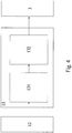
- Fig 4 is a circuit block diagram of a non-linear temperature-controlling unit of a temperature detecting and controlling integration device.
- the non-linear temperature-controlling unit 13 includes a data storage module 131 and a data conversion module 132.
- the data storage module 131 is used for receiving and storing the value of the power term a, a current temperature T, a comparsion reference temperature T 0 , a coefficient A and a coefficient B.
- the data conversion module 132 will access the data from the data storage module 131 to calculate the temperature change rates ⁇ T/ ⁇ t to obtain the compensaion gain ⁇ G according to formula (3) when the data conversion module 132 performs an operation. Accordingly, the compensation gain ⁇ G is used for driving the power amplifier 3.
- the data storage module 131 may be SRAM, DRAM, or flash memory, but it is not limited herein.
- an analog to digital conveter (ADC) further arranged in front of the current filter 8 and the voltage filter 9, in which the analog to digital conveter includes the analog-to-digital converters 6, 7.
- the analog-to-digital converters 6, 7 convert the anaolg type of coil thermal voltage signal and the extracted signal into the digital type of the extracted signal and the coil thermal voltage signal.
- the analog-to-digital converters 6, 7 are used for simplifying the operation process of the arithmetic unit 12 and converting the extracted signal and the coil thermal voltage signal into the readable format for the current filter 8 and the voltage filter 9.
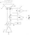
- Fig. 3 is a circuit block diagram of driving and extracting signal of a temperature detecting and controlling integration device of another embodiment of the present invention.
- Fig. 3 shows the signal transmittion between the power amplifier 3, the adder 2, the extraction resistor 4, the micro speaker 5 and the analog-to-digital converter 6, 7 of Fig. 2 in more detail.
- the output terminal of the power amplifier 3 inlcudes two ports.
- the power amplifier 3 is a double-ended output power amplifier 3.
- the input terminal and the output terminal of the adder 2 respectively include two ports for receiving an audio signal and outputting the adding signal.
- the micro speaker 5 receives the adding signal that outputted from the adder 3.
- the micro speaker 5 operates to emits a sound signal K and generates a coil thermal voltage signal at the same time.
- the two ports of the input terminal of the analog-to-digital converter 6 are coupled to the two ends of the extraction resistor 4 respectively for capturing the current components in the extracted signal.
- the operation principle of the extraction resistor is that the two ends of the analog-to-digital converter 6 capture the voltages V1, V2 at two ends of the extraction resistor 4. Then, the extraction resistor 4 substracts voltage V2 and voltage V1 to obtain the difference.
- the difference value of V2 and V1 is divided by the resistance value of the extraction resistor 4 so as to the current component in the extracted signal at a specific time can be obtained.
- the two input terminals of the analog-to-digital converter 7 are coupled with the two ends (such as a positive end and a negative end) of the big coil 51 of the micro speaker 5 respectively for capturing the voltages at two ends of the big coil 51 of the micro speaker 5 at a specific time, in which the voltages can be regards as the coil thermal voltage signal.
- the analog-to digital converter 7 substracts the voltages at two ends to obtain a voltage differences and is outputed to the post end.
- the analog-to-digital converteers 6, 7 have a function similar to a triple-use meter, which allows the user to read the voltage and the current values.
- the present invention provides a method for detecting the coil temperature in the micro speaker. Please return to Fig. 2 .
- the processing flow for the micro speaker 5 is separated into a pre-processing flow and a post-processing flow.
- the pre-processing flow refers to the temperature detecting and controlling integration device to receive the external input signal to play the sound.
- the post-processing flow refers to the temperature detecting and controlling integration device to receive the signal from the micro speaker 5 and the external device T3 to display the temperature.
- the distinction used the analog-to-digital converters 6, 7 as the basic to distinguish the pre-components and the post-components.
- the components in fron of the analog-to-digital converters 6, 7 refer to pre-components.
- Fig. 5 is a pre-processing flow chart of the temperature detecting and controlling integration device C.
- the step F1 to step F5 in Fig. 2 are described in detail below, and please refer to Fig. 5 .
- Step F1 the computer T1 provides an input signal.
- the temperature detecting and controlling integration device C is electrically connected to the computer T1 through the wires, buses, jumpers, or wirings on the printed circuit board (PCB).
- the standards for connection between the temperature detecting and controlling integration device C and the computer T1 may be by the way of USB, SATA, SATA2, or via solder joints. After connecting, the temperature detecting and controlling integration device C receives the input signal from the computer T1.
- Step F2 the filter 1 filters off the frequency in the input signal to generate an output signal after receiving the input signal from the computer T1.
- the received input signal includes various frequencies. and in the time of the signal transmission, the noise is easily incorporated into the input signal. Such noises are mostly in the low frequency.
- a filter 1 is set at the input terminal to filter off the first frequency in the input signal.
- the range of the first fgrequency is above 0 Hz, and not more than 50 Hz.
- Step F3 the power amplifier 3 adjusts the amplitude of the output signal according to the compensation gain to form an audio signal.
- the non-linear temperature-controlling unit 13 controls the power amplification Ap of the power amplifier 3 to adjust the amplitude of the audio signal in real time, such that the sound signal K is outputted smoothly.
- Step F4 the adder 2 adds the audio signal and the marked signal to form an adding signal, in which the marked signal is generated by a specific waveform generator T2.
- the marked signal is a signal frequency or multi-frequencies composite signals which is less than 50 Hz.
- the marked signal is to enable the extraction of the voltage signal and the current signal is more accurately, and to allow other components in the back-end to verify the accuracy of the signal extraction.
- Step F5 the micro speaker 5 is driven by the extracted signal to generate a coil thermal voltage signal. At this time, the micro speaker 5 is performed to emit the sound signal. At the same time, when the sound signal K is emitted, the conversion efficiency of electric energy and kinetic energy is not achieved 100%, the electric energy is dissipated from the coil in the form of thermal energy. Due to the thermoelectric effect, both the micro speaker coil current and the voltage signal are changed, and then are captured by the analog-to-digital converter.
- the pre-processing flow can be completed at the pre-preocessing flow or the process is connected to other processes. If the pre-processing flow is finished, the temperature detecting and controlling integration device C includes a control function, that is, a function of driving the micro speaker 5 to emit a sound.
- Fig. 6 is a post-processing flow chart of the temperature detecting and controlling integratiom device C.
- the step G1 to step G5 in Fig. 6 are described in detail below, and please also refer to Fig. 2 .
- Step G1 the analog-to-digital converters 6, 7 convert the analog types of the extracted signal and the coil thermal voltage signal into the digital types of the extracted signal and the coil thermal voltage signal. Since the analog signal is only readable by the micro speaker 5, for the convenience for facilitating the signal processing, the signal is converted to which is readable by the subsequent device, the analog-to-digital converters 6, 7 converts the analog types of the extracted signal and the coil thermal voltage signal into the digital types of the extracted signal and the coil thermal voltage signal.
- the analog type of the signal for example, an arbitrary natural number signal with a physical quantity of 0 volt, 1 volts, 2 volts, or 3 volts, but the digital signal is composed of only a combination of natural numbers 0 and 1, such as signal.
- a sigital is a binary signal such as 0011 or 1100.
- Step G2 the current filter 8 filters off the second frequency in the extracted signal to form a filtered current signal.
- the second frequency is in the range between 50 Hz-20,000 Hz.
- the purpose of the current filter 8 extracts a certain frequency range of the extracted signal is to obtain the thermal current signal.
- Step G3 the voltage filter 9 filters off the second frequency in the coil thermal voltage signal to form a filtered voltage signal.
- the second frequency is in the range between 50 Hz-20,000 Hz.
- the purposes of the voltage filter 9 extracts a certain frequency range of the extracted signal is to obtain the thermal voltage signal.
- step G4 is followed.
- step G3 and step G3 are performed simultaneously.
- Step G4 the filtered current signal and the filtered voltage signal are integrated respectively to form a current integrated signal and a voltage integrated signal.
- the current integrated signal is obtained by, for example, integrating the filtered current signal
- the voltage integrated signal is obtained by integrating the filtered voltage signal.
- the integral operation uses a current integrator 10 and a voltage integrator 11.
- the range of the ingetration can be selected from 1 second to 10 seconds, and the range of the integration is not limited herein.
- Step G5 the current integrated signal and the voltage integrated signal are calculated to generate a resistance signal.
- the temperature signal is generated after processing the resistance signal.
- the above-described operation is a division operation obtained by a divider (not shown in Fig. 2 ) in the arithmetic unit 12. It should be noted that the arithmetic unit 12 divides the current integrated signal and the voltage integrated signal that are obtained at the same time to obtain a resistance signal.
- the resistance signal is calcualted according to above formula (1), the steps of the calculation is not repeated herein.
- Step G6 the temperature is transmitted to the external device T3.
- the external device T3 is usually an electric thermometer or a smart phone.
- the temperature detecting and controlling integration device C is connected to the external device T3 via wires or jumpers, for example, by USB or printed circuit board wiring.
- the subsequent post-processing may be completed, or other processes may be followed. If the post-processing is finished, the temperature detecting and controlling integration device C capables of a function of detecting temperature, that is, he temperature detecting and controlling integration device C capables of a function of detecting the coil temperature in the micro speaker 5.
- Fig. 7 is a flow chart of an adjustment mode. The details of the process of the adjustment mode are described below, including steps H1 to H6.
- Step H1 the arithmetic unit 12 transmits the temperature into the non-linear temperature-controlling unit 13, in which the temperature signal includes a coefficient A, a coefficent B, the current temperature T and a comparsion reference temperture T 0 .
- Step H2 the data storage module 131 of the non-linear temperature-controlling unit 13 is used for storing the temperature signal.
- the temperature signal can be permanently stored by temporarily registed in the data storage module 131.
- Step H3 to determine whether to perform adaptive processing, if it is, to perform step H4, else, to perform step H5.
- the detailed determination steps is described in detail as following. Please refer to Fig. 8(a)-Fig. 8(c).
- Fig. 8(a)-Fig. 8(c) are shows the waveform diagrams of thifth node N5, the second node N2, and the third node N3 when the adaptive processing is performed.
- the determination is processed by the data storage module 131 of the non-linear temperature-controlling device 13. As shown in Fig.
- the data storage module 131 when the arithmetic unit 12 emits the temperature signal to the non-linear temperature-controlling device 13, the data storage module 131 will determine whether the current temperature T of the temperature signal (the signal of the fifth node N5) is within the rated temperature range. If the current temperature T is not within the rated temperature range, the data storage module 131 directly passes the data to the data conversion module 132, that is, step H5 is to be performed. If the current temperature T is within the rated temperature range, as shown in Fig. 8(a) , the current temperature T falls just below the lower limit of the rated temperature at the third second, and at this time, the data storage module 131 will perform adaptive processing., that is, step H4 is to be performed.
- the current temperature T of the temperature detecting and controlling integration device C is an unstable value which is changed with the time, and the frequency of data acquisition by the data storage module 131 is once every second. If the current temperature T jumps to the rated temperature, the adaptive processing will start immediately.
- Step H4 an adaptive process is performed.
- the adaptive process is that the operation is performed to generate a temperature change rate ⁇ T/ ⁇ t.
- the principle of detailed adaptive process is described in Fig. 8(a) .
- the data conversion module 132 automatically locates the I point, in which the I point is the temperature T1 at time t1 is 2 seconds, the data consersion module 132 calculates the temperature change rate ⁇ T/ ⁇ t from the data of the I point and the J point.
- Step H5 the data conversion module 132 of the non-linear temperature-controlling unit 13 captures the stored data in the data storage module 131 to calculate to form a compensation gain ⁇ G.
- the data conversion module 132 will capture the coefficient A, the coefficient B, the power term a, the current temperature T, the compensation reference temperature T0, and the temperature change rate ( ⁇ T/ ⁇ t) and calculates according to above formula (3) to obtain the compensation gain ⁇ G.
- Step H6 the compensation gain ⁇ G is transmitted to the power amplifier 3 to drive the power amplifier 3 for amplifying the signal.
- the power amplifier 3 utilizes Ap to amplify the output signal from the filter 1.
- the adjustment mode process is finished, or other processes may be peroformed subsequently. If the adjustment mode is finished, the temperature detecting and controlling integration device C includes a function of adjusting the power amplification rate of the power amplifier 3.
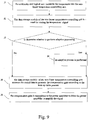
- Fig. 9 is a flow chat of a look-up table in a temperature detecting and controlling device.
- the look-up table process is is described in detail as following.
- the look-up table process includes step J1 to step J6. Since the contents of step J1, step J4 and step J6 are the same as above step H1 and the step H4 and the step H6, which has been described as aforementioned. Accordingly, it is not to be described herein. It is mainly illustrated for step J5.
- Step J5 utilizes the data storage module 131 of the non-linear temperature-controlling unit 13 to store the temperature signal, in which the temperature signal, for example, a coefficient A, a coefficient B, a power term a, a current temperature T, and a comparsion reference temperature T 0 .
- a look-up table is pre-programmed and is stored in the data storage module 131.
- the contents of the look-up table are shown in table 1, in which the table 1 shows the different values of the compensation gain ⁇ G for different temperature T and temperature change rate ( ⁇ T/ ⁇ t). Please refer to table 1, the horizontal columns show the different value of the temperature change rate ( ⁇ T/ ⁇ t), and the vertical columns show the different current temperature T value.
- the table content shows the compensation gain ⁇ G at a sepcific temperature change rate ( ⁇ T/ ⁇ t) and the compensation gain ⁇ G at the specific temeprature T.
- the combination of the different current temperature T and the temperature change rate ( ⁇ T/ ⁇ t) also represents that the compensation gain ⁇ G exists at a different addess of the data storage module 131.
- the data conversion moduel 132 looks up the correlation value stored in the table in the data storage module 131 according to the received current temperature T and the temperature change rate ( ⁇ T/ ⁇ t), and performs the look-up table process to find out a specific compensation gain ⁇ G.
- the data conversion module 132 receives a temperature change rate ( ⁇ T/ ⁇ t) is 4 and the current temperature T is 105, the compensation gain ⁇ G is -12. Then, the data conversion module 132 transmits the compensation gain ⁇ G ( ⁇ G is -12) to the power amplifier 3. Step J4 will be performed after step J3 is completed.
- step J6 the look-up table process is also finished, or other process may be performed subsequently.
- the temperature detecting and controlling integration device C includes a function of adjusting the power amplification of the power amplifier 3.
- the non-linear temperature-controlling unit 13 of the present invention furtehr includes a switch module (not shown in Fog. 4).
- the user can automatically switch the desired mode, including the adjustment mode and look-up table mode, so that the compensation gain ⁇ G can be quickly obtained.
- the switch module is usually a switching circuit.
- the non-linear temperature-controlling unit 13 makes a prediction on the future coil temperature based on the current temperature T, and then sends a control command to the power amplifier 3 to change the played amplitude of the audio signal and maintain the temperature within the temperature rated range.
Landscapes
- Engineering & Computer Science (AREA)
- Physics & Mathematics (AREA)
- Acoustics & Sound (AREA)
- Signal Processing (AREA)
- Multimedia (AREA)
- Health & Medical Sciences (AREA)
- General Health & Medical Sciences (AREA)
- Otolaryngology (AREA)
- Power Engineering (AREA)
- Amplifiers (AREA)
Applications Claiming Priority (3)
| Application Number | Priority Date | Filing Date | Title |
|---|---|---|---|
| CN201711059595 | 2017-11-01 | ||
| CN201711080667.7A CN107702813B (zh) | 2017-11-01 | 2017-11-06 | 微型扬声器控制测温整合装置及方法 |
| CN201810492803 | 2018-05-22 |
Publications (4)
| Publication Number | Publication Date |
|---|---|
| EP3480952A2 true EP3480952A2 (de) | 2019-05-08 |
| EP3480952A3 EP3480952A3 (de) | 2019-06-12 |
| EP3480952C0 EP3480952C0 (de) | 2024-08-14 |
| EP3480952B1 EP3480952B1 (de) | 2024-08-14 |
Family
ID=62630960
Family Applications (1)
| Application Number | Title | Priority Date | Filing Date |
|---|---|---|---|
| EP18177414.2A Active EP3480952B1 (de) | 2017-11-01 | 2018-06-12 | Temperaturerkennungs- und -steuerungsintegrationsvorrichtung und das für mikrolautsprecher angewandte temperatursteuerungsverfahren |
Country Status (2)
| Country | Link |
|---|---|
| US (2) | US10531193B2 (de) |
| EP (1) | EP3480952B1 (de) |
Cited By (1)
| Publication number | Priority date | Publication date | Assignee | Title |
|---|---|---|---|---|
| CN111541975A (zh) * | 2020-04-27 | 2020-08-14 | 维沃移动通信有限公司 | 音频信号的调节方法及电子设备 |
Families Citing this family (5)
| Publication number | Priority date | Publication date | Assignee | Title |
|---|---|---|---|---|
| US10903802B2 (en) * | 2019-02-01 | 2021-01-26 | Texas Instruments Incorporated | Analog based speaker thermal protection in class-D amplifiers |
| CN110336540B (zh) * | 2019-06-28 | 2024-02-23 | 上海韦尔半导体股份有限公司 | 一种温度控制电路 |
| CN116735024A (zh) * | 2022-03-02 | 2023-09-12 | 北京小米移动软件有限公司 | 扬声器检测系统、方法及电子设备 |
| DE202022104014U1 (de) | 2022-07-15 | 2022-08-16 | Uttaranchal University | Ein System zur Erkennung der mobilen Temperatur mit Xgbee und IoT |
| TWI837930B (zh) * | 2022-11-04 | 2024-04-01 | 立錡科技股份有限公司 | 包含多組揚聲器和單一功能晶片之電子裝置 |
Family Cites Families (11)
| Publication number | Priority date | Publication date | Assignee | Title |
|---|---|---|---|---|
| EP3076545B1 (de) * | 2010-02-10 | 2020-12-16 | Goodix Technology (HK) Company Limited | System und verfahren zur anpassung eines lautsprechersignals |
| EP2538555B1 (de) * | 2011-06-22 | 2019-09-11 | Nxp B.V. | Steuerung einer Lautsprecherausgabe |
| US9161126B2 (en) * | 2013-03-08 | 2015-10-13 | Cirrus Logic, Inc. | Systems and methods for protecting a speaker |
| EP2806656B1 (de) * | 2013-05-21 | 2016-04-13 | ST-Ericsson SA | Lautsprecherwärmeregelung mit Statusbeobachtung |
| US9980068B2 (en) * | 2013-11-06 | 2018-05-22 | Analog Devices Global | Method of estimating diaphragm excursion of a loudspeaker |
| GB2526881B (en) * | 2014-06-06 | 2017-10-04 | Cirrus Logic Int Semiconductor Ltd | Temperature monitoring for loudspeakers |
| US9414160B2 (en) * | 2014-11-27 | 2016-08-09 | Blackberry Limited | Method, system and apparatus for loudspeaker excursion domain processing |
| GB2594648B (en) * | 2015-05-22 | 2022-04-20 | Cirrus Logic Int Semiconductor Ltd | Adaptive receiver |
| US9807528B1 (en) * | 2015-09-21 | 2017-10-31 | Apple Inc. | Electronic devices and method for thermal monitoring of an electro-mechanical actuator |
| US10165361B2 (en) * | 2016-05-31 | 2018-12-25 | Avago Technologies International Sales Pte. Limited | System and method for loudspeaker protection |
| US10264355B2 (en) * | 2017-06-02 | 2019-04-16 | Apple Inc. | Loudspeaker cabinet with thermal and power mitigation control effort |
-
2018
- 2018-06-12 EP EP18177414.2A patent/EP3480952B1/de active Active
- 2018-08-31 US US16/119,838 patent/US10531193B2/en active Active
-
2019
- 2019-11-13 US US16/682,454 patent/US10834504B2/en active Active
Non-Patent Citations (1)
| Title |
|---|
| None |
Cited By (2)
| Publication number | Priority date | Publication date | Assignee | Title |
|---|---|---|---|---|
| CN111541975A (zh) * | 2020-04-27 | 2020-08-14 | 维沃移动通信有限公司 | 音频信号的调节方法及电子设备 |
| CN111541975B (zh) * | 2020-04-27 | 2021-05-07 | 维沃移动通信有限公司 | 音频信号的调节方法及电子设备 |
Also Published As
| Publication number | Publication date |
|---|---|
| EP3480952A3 (de) | 2019-06-12 |
| US10531193B2 (en) | 2020-01-07 |
| EP3480952C0 (de) | 2024-08-14 |
| EP3480952B1 (de) | 2024-08-14 |
| US20200084542A1 (en) | 2020-03-12 |
| US20190132675A1 (en) | 2019-05-02 |
| US10834504B2 (en) | 2020-11-10 |
Similar Documents
| Publication | Publication Date | Title |
|---|---|---|
| US10834504B2 (en) | Temperature detecting and controlling integration device and the temperature controlling method applied for micro speaker | |
| US8428278B2 (en) | Improvements to systems for acoustic diffusion | |
| CN101924525B (zh) | 高性能音频放大电路 | |
| KR101601229B1 (ko) | 마이크로폰 | |
| JP2014006253A (ja) | ブザーのテスト回路 | |
| WO2011044395A1 (en) | An input signal mismatch compensation system | |
| JP7281781B2 (ja) | マイクロホンモジュール及び該マイクロホンモジュールの検査装置 | |
| CN212628418U (zh) | 扬声器检测系统 | |
| CN114945119B (zh) | 定向带式麦克风组件 | |
| CN112565976B (zh) | 扬声器的驱动电路、温度保护方法、终端设备及存储介质 | |
| CN109297614B (zh) | 基于相位变化测量的喇叭温度保护方法 | |
| CN116055955B (zh) | 一种消音电路及芯片 | |
| CN110677798A (zh) | 具有自校准功能的传声器及其校准方法、传声系统和声音检测系统 | |
| CN107702813B (zh) | 微型扬声器控制测温整合装置及方法 | |
| CN211321499U (zh) | 扬声器控制电路及音频播放装置 | |
| CN219087308U (zh) | 一种用于降噪处理的微机电麦克风结构及串联麦克风结构 | |
| US20200319843A1 (en) | Reconfigurable microphone assembly | |
| CN216905215U (zh) | 数字麦克风集成芯片电路及数字麦克风 | |
| EP3480569B1 (de) | Schallausgabevorrichtung und musikinstrument | |
| US8159292B2 (en) | Amplifying circuit | |
| JP2001169384A (ja) | スピーカシステム | |
| CN220629582U (zh) | 一种扬声器故障的检测装置及广播终端 | |
| CN116132865B (zh) | 骨传导麦克风及降噪方法 | |
| CN109925003B (zh) | 一种胎心信号处理电路及胎儿心率仪 | |
| CN207779580U (zh) | 一种扬声器控制与测温的整合装置 |
Legal Events
| Date | Code | Title | Description |
|---|---|---|---|
| PUAI | Public reference made under article 153(3) epc to a published international application that has entered the european phase |
Free format text: ORIGINAL CODE: 0009012 |
|
| STAA | Information on the status of an ep patent application or granted ep patent |
Free format text: STATUS: REQUEST FOR EXAMINATION WAS MADE |
|
| 17P | Request for examination filed |
Effective date: 20181012 |
|
| AK | Designated contracting states |
Kind code of ref document: A2 Designated state(s): AL AT BE BG CH CY CZ DE DK EE ES FI FR GB GR HR HU IE IS IT LI LT LU LV MC MK MT NL NO PL PT RO RS SE SI SK SM TR |
|
| AX | Request for extension of the european patent |
Extension state: BA ME |
|
| PUAL | Search report despatched |
Free format text: ORIGINAL CODE: 0009013 |
|
| AK | Designated contracting states |
Kind code of ref document: A3 Designated state(s): AL AT BE BG CH CY CZ DE DK EE ES FI FR GB GR HR HU IE IS IT LI LT LU LV MC MK MT NL NO PL PT RO RS SE SI SK SM TR |
|
| AX | Request for extension of the european patent |
Extension state: BA ME |
|
| RIC1 | Information provided on ipc code assigned before grant |
Ipc: H04R 3/00 20060101ALI20190509BHEP Ipc: H03G 7/00 20060101ALI20190509BHEP Ipc: H03G 7/08 20060101ALI20190509BHEP Ipc: H03G 3/30 20060101AFI20190509BHEP Ipc: H04R 29/00 20060101ALI20190509BHEP |
|
| RBV | Designated contracting states (corrected) |
Designated state(s): AL AT BE BG CH CY CZ DE DK EE ES FI FR GB GR HR HU IE IS IT LI LT LU LV MC MK MT NL NO PL PT RO RS SE SI SK SM TR |
|
| STAA | Information on the status of an ep patent application or granted ep patent |
Free format text: STATUS: EXAMINATION IS IN PROGRESS |
|
| 17Q | First examination report despatched |
Effective date: 20210805 |
|
| RAP3 | Party data changed (applicant data changed or rights of an application transferred) |
Owner name: SHANGHAI FOURSEMI SEMICONDUCTOR CO., LTD. |
|
| GRAP | Despatch of communication of intention to grant a patent |
Free format text: ORIGINAL CODE: EPIDOSNIGR1 |
|
| STAA | Information on the status of an ep patent application or granted ep patent |
Free format text: STATUS: GRANT OF PATENT IS INTENDED |
|
| INTG | Intention to grant announced |
Effective date: 20240305 |
|
| GRAS | Grant fee paid |
Free format text: ORIGINAL CODE: EPIDOSNIGR3 |
|
| GRAA | (expected) grant |
Free format text: ORIGINAL CODE: 0009210 |
|
| STAA | Information on the status of an ep patent application or granted ep patent |
Free format text: STATUS: THE PATENT HAS BEEN GRANTED |
|
| AK | Designated contracting states |
Kind code of ref document: B1 Designated state(s): AL AT BE BG CH CY CZ DE DK EE ES FI FR GB GR HR HU IE IS IT LI LT LU LV MC MK MT NL NO PL PT RO RS SE SI SK SM TR |
|
| REG | Reference to a national code |
Ref country code: GB Ref legal event code: FG4D |
|
| REG | Reference to a national code |
Ref country code: CH Ref legal event code: EP |
|
| REG | Reference to a national code |
Ref country code: DE Ref legal event code: R096 Ref document number: 602018073014 Country of ref document: DE |
|
| REG | Reference to a national code |
Ref country code: IE Ref legal event code: FG4D |
|
| U01 | Request for unitary effect filed |
Effective date: 20240913 |
|
| U07 | Unitary effect registered |
Designated state(s): AT BE BG DE DK EE FI FR IT LT LU LV MT NL PT RO SE SI Effective date: 20241002 |
|
| PG25 | Lapsed in a contracting state [announced via postgrant information from national office to epo] |
Ref country code: NO Free format text: LAPSE BECAUSE OF FAILURE TO SUBMIT A TRANSLATION OF THE DESCRIPTION OR TO PAY THE FEE WITHIN THE PRESCRIBED TIME-LIMIT Effective date: 20241114 |
|
| PG25 | Lapsed in a contracting state [announced via postgrant information from national office to epo] |
Ref country code: GR Free format text: LAPSE BECAUSE OF FAILURE TO SUBMIT A TRANSLATION OF THE DESCRIPTION OR TO PAY THE FEE WITHIN THE PRESCRIBED TIME-LIMIT Effective date: 20241115 Ref country code: PL Free format text: LAPSE BECAUSE OF FAILURE TO SUBMIT A TRANSLATION OF THE DESCRIPTION OR TO PAY THE FEE WITHIN THE PRESCRIBED TIME-LIMIT Effective date: 20240814 |
|
| PG25 | Lapsed in a contracting state [announced via postgrant information from national office to epo] |
Ref country code: IS Free format text: LAPSE BECAUSE OF FAILURE TO SUBMIT A TRANSLATION OF THE DESCRIPTION OR TO PAY THE FEE WITHIN THE PRESCRIBED TIME-LIMIT Effective date: 20241214 |
|
| PG25 | Lapsed in a contracting state [announced via postgrant information from national office to epo] |
Ref country code: HR Free format text: LAPSE BECAUSE OF FAILURE TO SUBMIT A TRANSLATION OF THE DESCRIPTION OR TO PAY THE FEE WITHIN THE PRESCRIBED TIME-LIMIT Effective date: 20240814 |
|
| PG25 | Lapsed in a contracting state [announced via postgrant information from national office to epo] |
Ref country code: RS Free format text: LAPSE BECAUSE OF FAILURE TO SUBMIT A TRANSLATION OF THE DESCRIPTION OR TO PAY THE FEE WITHIN THE PRESCRIBED TIME-LIMIT Effective date: 20241114 Ref country code: ES Free format text: LAPSE BECAUSE OF FAILURE TO SUBMIT A TRANSLATION OF THE DESCRIPTION OR TO PAY THE FEE WITHIN THE PRESCRIBED TIME-LIMIT Effective date: 20240814 |
|
| PG25 | Lapsed in a contracting state [announced via postgrant information from national office to epo] |
Ref country code: RS Free format text: LAPSE BECAUSE OF FAILURE TO SUBMIT A TRANSLATION OF THE DESCRIPTION OR TO PAY THE FEE WITHIN THE PRESCRIBED TIME-LIMIT Effective date: 20241114 Ref country code: PL Free format text: LAPSE BECAUSE OF FAILURE TO SUBMIT A TRANSLATION OF THE DESCRIPTION OR TO PAY THE FEE WITHIN THE PRESCRIBED TIME-LIMIT Effective date: 20240814 Ref country code: NO Free format text: LAPSE BECAUSE OF FAILURE TO SUBMIT A TRANSLATION OF THE DESCRIPTION OR TO PAY THE FEE WITHIN THE PRESCRIBED TIME-LIMIT Effective date: 20241114 Ref country code: IS Free format text: LAPSE BECAUSE OF FAILURE TO SUBMIT A TRANSLATION OF THE DESCRIPTION OR TO PAY THE FEE WITHIN THE PRESCRIBED TIME-LIMIT Effective date: 20241214 Ref country code: HR Free format text: LAPSE BECAUSE OF FAILURE TO SUBMIT A TRANSLATION OF THE DESCRIPTION OR TO PAY THE FEE WITHIN THE PRESCRIBED TIME-LIMIT Effective date: 20240814 Ref country code: GR Free format text: LAPSE BECAUSE OF FAILURE TO SUBMIT A TRANSLATION OF THE DESCRIPTION OR TO PAY THE FEE WITHIN THE PRESCRIBED TIME-LIMIT Effective date: 20241115 Ref country code: ES Free format text: LAPSE BECAUSE OF FAILURE TO SUBMIT A TRANSLATION OF THE DESCRIPTION OR TO PAY THE FEE WITHIN THE PRESCRIBED TIME-LIMIT Effective date: 20240814 |
|
| PG25 | Lapsed in a contracting state [announced via postgrant information from national office to epo] |
Ref country code: SM Free format text: LAPSE BECAUSE OF FAILURE TO SUBMIT A TRANSLATION OF THE DESCRIPTION OR TO PAY THE FEE WITHIN THE PRESCRIBED TIME-LIMIT Effective date: 20240814 |
|
| PG25 | Lapsed in a contracting state [announced via postgrant information from national office to epo] |
Ref country code: CZ Free format text: LAPSE BECAUSE OF FAILURE TO SUBMIT A TRANSLATION OF THE DESCRIPTION OR TO PAY THE FEE WITHIN THE PRESCRIBED TIME-LIMIT Effective date: 20240814 |
|
| PG25 | Lapsed in a contracting state [announced via postgrant information from national office to epo] |
Ref country code: SK Free format text: LAPSE BECAUSE OF FAILURE TO SUBMIT A TRANSLATION OF THE DESCRIPTION OR TO PAY THE FEE WITHIN THE PRESCRIBED TIME-LIMIT Effective date: 20240814 |
|
| PLBE | No opposition filed within time limit |
Free format text: ORIGINAL CODE: 0009261 |
|
| STAA | Information on the status of an ep patent application or granted ep patent |
Free format text: STATUS: NO OPPOSITION FILED WITHIN TIME LIMIT |
|
| 26N | No opposition filed |
Effective date: 20250515 |
|
| U20 | Renewal fee for the european patent with unitary effect paid |
Year of fee payment: 8 Effective date: 20250628 |
|
| REG | Reference to a national code |
Ref country code: CH Ref legal event code: H13 Free format text: ST27 STATUS EVENT CODE: U-0-0-H10-H13 (AS PROVIDED BY THE NATIONAL OFFICE) Effective date: 20260127 |
|
| PG25 | Lapsed in a contracting state [announced via postgrant information from national office to epo] |
Ref country code: MC Free format text: LAPSE BECAUSE OF FAILURE TO SUBMIT A TRANSLATION OF THE DESCRIPTION OR TO PAY THE FEE WITHIN THE PRESCRIBED TIME-LIMIT Effective date: 20240814 |
|
| GBPC | Gb: european patent ceased through non-payment of renewal fee |
Effective date: 20250612 |
|
| PG25 | Lapsed in a contracting state [announced via postgrant information from national office to epo] |
Ref country code: GB Free format text: LAPSE BECAUSE OF NON-PAYMENT OF DUE FEES Effective date: 20250612 |
|
| PG25 | Lapsed in a contracting state [announced via postgrant information from national office to epo] |
Ref country code: IE Free format text: LAPSE BECAUSE OF NON-PAYMENT OF DUE FEES Effective date: 20250612 |
|
| PG25 | Lapsed in a contracting state [announced via postgrant information from national office to epo] |
Ref country code: CH Free format text: LAPSE BECAUSE OF NON-PAYMENT OF DUE FEES Effective date: 20250630 |