EP3480937A1 - Counter-field winding in electrical generator - Google Patents
Counter-field winding in electrical generator Download PDFInfo
- Publication number
- EP3480937A1 EP3480937A1 EP18183335.1A EP18183335A EP3480937A1 EP 3480937 A1 EP3480937 A1 EP 3480937A1 EP 18183335 A EP18183335 A EP 18183335A EP 3480937 A1 EP3480937 A1 EP 3480937A1
- Authority
- EP
- European Patent Office
- Prior art keywords
- main field
- field winding
- counter
- main
- winding
- Prior art date
- Legal status (The legal status is an assumption and is not a legal conclusion. Google has not performed a legal analysis and makes no representation as to the accuracy of the status listed.)
- Granted
Links
- 238000004804 winding Methods 0.000 title claims abstract description 206
- 238000000034 method Methods 0.000 claims abstract description 22
- 230000008878 coupling Effects 0.000 claims abstract description 15
- 238000010168 coupling process Methods 0.000 claims abstract description 15
- 238000005859 coupling reaction Methods 0.000 claims abstract description 15
- 230000003313 weakening effect Effects 0.000 claims abstract description 7
- 238000012546 transfer Methods 0.000 claims description 3
- 238000010586 diagram Methods 0.000 description 14
- 230000000670 limiting effect Effects 0.000 description 8
- 239000000463 material Substances 0.000 description 5
- 239000003990 capacitor Substances 0.000 description 2
- 238000002485 combustion reaction Methods 0.000 description 2
- 230000000295 complement effect Effects 0.000 description 2
- 230000007423 decrease Effects 0.000 description 2
- 230000005611 electricity Effects 0.000 description 2
- 238000013021 overheating Methods 0.000 description 2
- 230000021715 photosynthesis, light harvesting Effects 0.000 description 2
- 230000002829 reductive effect Effects 0.000 description 2
- 230000001360 synchronised effect Effects 0.000 description 2
- 238000013329 compounding Methods 0.000 description 1
- 238000004590 computer program Methods 0.000 description 1
- 238000012937 correction Methods 0.000 description 1
- 230000003247 decreasing effect Effects 0.000 description 1
- 230000001934 delay Effects 0.000 description 1
- 238000013461 design Methods 0.000 description 1
- 238000011161 development Methods 0.000 description 1
- 230000000694 effects Effects 0.000 description 1
- 230000005674 electromagnetic induction Effects 0.000 description 1
- 230000005669 field effect Effects 0.000 description 1
- 230000000116 mitigating effect Effects 0.000 description 1
- 230000036961 partial effect Effects 0.000 description 1
- 238000010248 power generation Methods 0.000 description 1
- 230000002441 reversible effect Effects 0.000 description 1
- 239000004065 semiconductor Substances 0.000 description 1
- XLYOFNOQVPJJNP-UHFFFAOYSA-N water Substances O XLYOFNOQVPJJNP-UHFFFAOYSA-N 0.000 description 1
Images


Classifications
-
- H—ELECTRICITY
- H02—GENERATION; CONVERSION OR DISTRIBUTION OF ELECTRIC POWER
- H02P—CONTROL OR REGULATION OF ELECTRIC MOTORS, ELECTRIC GENERATORS OR DYNAMO-ELECTRIC CONVERTERS; CONTROLLING TRANSFORMERS, REACTORS OR CHOKE COILS
- H02P9/00—Arrangements for controlling electric generators for the purpose of obtaining a desired output
- H02P9/10—Control effected upon generator excitation circuit to reduce harmful effects of overloads or transients, e.g. sudden application of load, sudden removal of load, sudden change of load
- H02P9/107—Control effected upon generator excitation circuit to reduce harmful effects of overloads or transients, e.g. sudden application of load, sudden removal of load, sudden change of load for limiting effects of overloads
-
- H—ELECTRICITY
- H02—GENERATION; CONVERSION OR DISTRIBUTION OF ELECTRIC POWER
- H02K—DYNAMO-ELECTRIC MACHINES
- H02K19/00—Synchronous motors or generators
- H02K19/16—Synchronous generators
- H02K19/26—Synchronous generators characterised by the arrangement of exciting windings
-
- H—ELECTRICITY
- H02—GENERATION; CONVERSION OR DISTRIBUTION OF ELECTRIC POWER
- H02P—CONTROL OR REGULATION OF ELECTRIC MOTORS, ELECTRIC GENERATORS OR DYNAMO-ELECTRIC CONVERTERS; CONTROLLING TRANSFORMERS, REACTORS OR CHOKE COILS
- H02P29/00—Arrangements for regulating or controlling electric motors, appropriate for both AC and DC motors
- H02P29/02—Providing protection against overload without automatic interruption of supply
- H02P29/024—Detecting a fault condition, e.g. short circuit, locked rotor, open circuit or loss of load
- H02P29/0241—Detecting a fault condition, e.g. short circuit, locked rotor, open circuit or loss of load the fault being an overvoltage
-
- H—ELECTRICITY
- H02—GENERATION; CONVERSION OR DISTRIBUTION OF ELECTRIC POWER
- H02K—DYNAMO-ELECTRIC MACHINES
- H02K3/00—Details of windings
- H02K3/04—Windings characterised by the conductor shape, form or construction, e.g. with bar conductors
- H02K3/18—Windings for salient poles
- H02K3/20—Windings for salient poles for auxiliary purposes, e.g. damping or commutating
-
- H—ELECTRICITY
- H02—GENERATION; CONVERSION OR DISTRIBUTION OF ELECTRIC POWER
- H02P—CONTROL OR REGULATION OF ELECTRIC MOTORS, ELECTRIC GENERATORS OR DYNAMO-ELECTRIC CONVERTERS; CONTROLLING TRANSFORMERS, REACTORS OR CHOKE COILS
- H02P2101/00—Special adaptation of control arrangements for generators
- H02P2101/30—Special adaptation of control arrangements for generators for aircraft
Abstract
Description
- Examples of the present disclosure relate generally to electrical generators, and more specifically to techniques for addressing undesired effects of main field current in an electrical generator under certain conditions. Generators are used to generate a majority of the power on current electric power grids. These generators, which can be synchronous generators or permanent magnet generators, for example, are used to convert mechanical energy from internal combustion, wind, nuclear, and hydraulic sources, for example, into electrical energy. Modern generators can produce hundreds of megawatts each.
- Modern wound-rotor generators include a rotor and a stator, each with one or more electrical windings. A magnetic field on the rotating rotor is generated by a current passing through the rotor winding, which induces an electrical current in the stator winding(s) and creates alternating current (AC) electricity. An output voltage of the generator can be controlled by controlling the current flow in the rotor winding (and therefore the strength of the magnetic field, which induces a voltage on the stator winding(s)). In some cases, the current flow in the rotor winding may be supplied by a direct electrical connection to the generator controller using, e.g., slip rings. In other cases, the current flow may be controlled from the generator controller using an armature winding to the rotor through electromagnetic induction. One or more loads can be connected to, and powered by, the output of the stator. In some examples, the output of the stator can be rectified to produce direct current (DC) electricity.
- During a load fault condition, such as a short-circuit fault occurring in the load, the electrical energy delivered by the electrical generator to the load should be limited to reduce a severity of consequences of the fault. However, even though the generator controller can turn off the exciter current, the rotor magnetic field will not immediately fall to zero due to the stored magnetic energy in the main field windings and a relatively large time constant. This condition results in the field current "free-wheeling" through the components of the rotor which, in turn, causes the main armature to continue producing current. Unfortunately, this current is being provided to a short-circuit, compounding the problem. This makes it difficult to clear the load fault (i.e., because it is still energized) and can overheat both the rotor and the stator. If this condition persists long enough, there is a risk of permanent damage to the load, the distribution system, and/or the generator. To address these and other issues, the present disclosure is submitted.
- According to one or more examples, a main field circuit of an electrical generator comprises a main field winding configured to conduct a main field current, and a counter-field winding arranged proximate to the main field winding. The main field circuit further comprises a switch element configured to selectively couple at least a portion of the main field current into the counter-field winding to reduce a magnitude of the main field current.
- According to one or more examples, a system comprises an electrical generator comprising: a first rotor winding configured to conduct a main field current, and a second rotor winding arranged proximate to the main field winding. The system further comprises a first switch element arranged in series with the second rotor winding, and a controller configured to operate the first switch element to selectively couple at least a portion of the main field current into the second rotor winding to reduce a magnitude of the main field current.
- According to one or more examples, a method for use with an electrical generator comprises conducting a main field current through a main field winding of the electrical generator, and, responsive to a predefined condition, coupling at least a portion of the main field current into a counter-field winding that is arranged proximate to the main field winding. Coupling at least a portion of the main field current into the counter-field winding operates to reduce a magnitude of the main field current.
- The features, functions, and advantages that have been discussed may be achieved independently in various examples or may be combined in yet other examples, further details of which can be seen with reference to the following description and drawings.
- So that the manner in which the above recited features of the present disclosure can be understood in detail, a more particular description of the disclosure, briefly summarized above, may be had by reference to examples, some of which are illustrated in the appended drawings. It is to be noted, however, that the appended drawings illustrate only typical examples of this disclosure and are therefore not to be considered limiting of its scope, for the disclosure may admit to other equally effective examples.
-
Figure 1 is a block diagram depicting a three-stage electrical generator. -
Figure 2 is a circuit schematic depicting an electrical generator during a load fault condition. -
Figure 3 is a circuit schematic depicting exemplary normal operation of an electrical generator having a counter-field winding, according to examples disclosed herein. -
Figure 4 is a circuit schematic depicting exemplary load-fault operation of an electrical generator having a counter-field winding, according to examples disclosed herein. -
Figure 5A is a diagram illustrating a rotor having a plurality of slots during exemplary normal operation, according to examples disclosed herein. -
Figure 5B is a diagram illustrating a rotor having a plurality of slots during exemplary load-fault operation, according to examples disclosed herein. -
Figure 6 is a method for use with an electrical generator, according to examples disclosed herein. - To facilitate understanding, identical reference numerals have been used, where possible, to designate identical elements that are common to the figures. It is contemplated that elements disclosed in one example may be beneficially utilized on other examples without specific recitation. The illustrations referred to here should not be understood as being drawn to scale unless specifically noted. Also, the drawings are often simplified and details or components omitted for clarity of presentation and explanation. The drawings and discussion serve to explain principles discussed below, where like designations denote like elements.
- Examples of the present disclosure relate generally to electrical generators, and more specifically to techniques for rapidly dissipating main field current in an electrical generator using a counter-field winding arranged proximate to a main field winding. The main field winding is configured to conduct a main field current, and the counter-field winding is arranged such that the main field current flows through the counter-field winding in a direction opposite to the main field winding. In some cases, the net magnetic field generated by the main field winding and the counter-field winding is substantially zero, which substantially eliminates the current that is delivered to the load.
- In some examples, a switch element is configured to selectively couple at least a portion of the main field current into the counter-field winding to reduce a magnitude of the main field current. Some examples may further include a controller, one or more additional switch elements, one or more logic gates, and/or one or more energy dissipation elements. Some non-limiting examples of energy dissipation elements include a resistor, a capacitor, a battery, and so forth.
- In some examples, the rapid dissipation of the main field current occurs responsive to a predefined condition, such as a predefined load fault condition or the enabling of a predefined field weakening operation. The coupling of the portion of the main field current into the counter-field winding operates to significantly reduce a time constant associated with the main field winding, which in the case of a load fault condition allows a load fault to be cleared more quickly while also protecting the components of the electrical generator.
- In some examples, the energy in the main field can be dissipated autonomously and without signals from external control circuits. Such a feature greatly simplifies the design and reduces wiring complexity, which tends to increase reliability of the system. In some examples, the system can be implemented entirely on and/or in the rotor. In some examples, the system can operate using two voltage regimes: (1) a normal operating voltage (or normal voltage range) and (2) a voltage outside the normal operating voltage or normal voltage range. Thus, if the system is operating at a voltage outside the normal operating voltage or normal voltage range, the main field energy can be extracted to enable fault correction.
- The materials and components described hereinafter as making up the various elements of the present disclosure are intended to be illustrative and not restrictive. Many suitable materials and components that would perform the same or a similar function as the materials and components described herein are intended to be embraced within the scope of the disclosure. Such other materials and components not described herein can include, but are not limited to, materials and components that are developed after the time of the development of the disclosure.
-
Figure 1 is a block diagram depicting a three-stageelectrical generator 100. As shown, theelectrical generator 100 comprises a synchronous generator, but other types of electrical generators and/or numbers of stages are also contemplated. Theelectrical generator 100 comprises a rotation section (or "rotor") 105 and a stationary section (or "stator") 110. Within a permanent magnet (PMG)stage 130, apermanent magnet 120 is mounted on therotor 105, and one or moremain windings 135 are mounted on thestator 110. Therotor 105 is coupled with a mechanical power source, some non-limiting examples of which include an internal combustion engine, a turbine powered using wind, steam, or water, and so forth. - In an exciter stage of the
electrical generator 100, an exciterfield stator winding 140 is mounted on thestator 110 and is communicatively coupled with agenerator control unit 145 that is configured to regulate the exciter field current generated from thePMG stage 130. In the exciter stage, one or more exciterfield armature windings 150 are located on therotor 105. The output current from the exciterfield armature windings 150 are rectified by a three-phase rectifier 155 to produce a DC current. The rectified DC current is then conducted to the main field winding 160 of a main stage of theelectrical generator 100. - The main stage comprises the main field winding 160 located on the
rotor 105, and one or more main armature windings 165 (as shown, three windings corresponding to three-phase power generation) located on thestator 110. The three-phase output 170 from themain armature windings 165 may be connected to a distribution bus, fuse panel, or directly to one or more loads. - Although not shown, the exciter stage may further comprise an exciter power supply and an exciter driver coupled with the one or more
main windings 135. Thegenerator control unit 145 can vary the voltage and/or current to the exciter driver to control the output voltage and current generated by theelectrical generator 100. -
Figure 2 is a circuit schematic depicting anelectrical generator 200 during a load fault condition. As discussed above, one problem that occurs in theelectrical generator 200 is when aload 205 that is coupled with the three-phase output 170 experiences a load fault. Some non-limiting examples of the load fault include a partial or complete short circuit occurring in theload 205. In the case of a load fault, the associated generator control unit (e.g.,generator control unit 145 ofFigure 1 ) senses the load fault and responsively shuts off the current provided by the exciter field armature windings 150 (e.g., by disabling output to the one or more main windings 135). - However, even reducing the current provided by the exciter
field armature windings 150 to zero does not operate to stop the main field current if immediately, due to the established energy in the main field winding 160 and the relatively large time constant associated with themain field circuit 210. Because the diodes of therectifier 155 present a relatively small resistance Rd, and dissipate relatively little power through their forward voltage drop, the simple RL circuit formed by themain field circuit 210 has a relatively large time constant (Lf / Rd), causing the main field current if to have a large amplitude for a relatively long duration, which delays the shutdown of theelectrical generator 200. - As a result, the main field current if continues to flow or "free-wheel" around the
main field circuit 210 following a load fault. Although the main field current if will slowly decrease, during this time theelectrical generator 200 continues to supply current (illustrated as phase currents ia, ib, ic) to theload 205 with a known load fault as long as the main field persists. Because themain armature windings 165 continue to provide a relatively large current to theload 205, this makes it difficult to clear the load fault. Additionally, the high currents in themain armature windings 165 can result in the overheating of various components of theelectrical generator 200, such as the windings and/or a wiring harness (not shown), and may further damage theload 205. Thus, the free-wheeling main field current if can delay or prevent theelectrical generator 200 from reentering service, and can potentially cause damage to theelectrical generator 200 and/or associated wiring. -
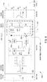
Figure 3 is a circuit schematic depicting exemplary normal operation of anelectrical generator 300 having a counter-field winding 345, according to examples disclosed herein. In some cases, "normal" operation of theelectrical generator 300 corresponds to a condition in which no load fault is detected. In some cases, "normal" operation of theelectrical generator 300 corresponds to a condition in which a field weakening operation is not enabled. While components of the exciter stage and the main stage of theelectrical generator 300 are depicted, components of the PMG stage are not depicted. - In the
electrical generator 300, themain field circuit 350 comprises acontroller 305, alogic gate 310, one ormore switch drivers controllable switch elements controller 305 may comprise one or more computer processors in any suitable implementation. Some non-limiting examples of thecontroller 305 include a microprocessor, a digital signal processor (DSP), an application-specific integrated chip (ASIC), and a field programmable gate array (FPGA). In another example implementation, thecontroller 305 may be as simple as a single comparator configured to compare an output voltage with a nominal voltage. For such an example implementation, no-fault operation of theelectrical generator 300 may correspond to the nominal voltage, and a load fault is indicated by an output voltage different than the nominal voltage. In yet another example implementation, thecontroller 305 may determine whether an output voltage falls within a predefined voltage range, and a load fault is indicated by the output voltage that falls outside the predefined voltage range. - The
logic gate 310 is communicatively coupled with an output of thecontroller 305. As shown, thelogic gate 310 provides complementary outputs to the twoswitch drivers respective switch elements electrical generator 300, thecontroller 305 outputs a logic "high" signal to thelogic gate 310. In turn, thelogic gate 310 transmits a logic "high" to theswitch driver 315a to maintain theswitch element 320a in a conducting state, and transmits a logic "low" to switchdriver 315b to maintain theswitch element 320b in a non-conducting state, and vice versa. While thelogic gate 310 is depicted as a complementary buffer element, additional or alternative logic may be implemented in themain field circuit 350. In an alternate example, thelogic gate 310 and/or the switch drivers 315 may be integrated in thecontroller 305. - The
switch drivers switch drivers switch elements switch drivers main field circuit 350. In an alternate example, theswitch drivers switch elements logic gate 310 or from thecontroller 305. - The
switch elements switch elements - The main field winding 160 is arranged between a
first leg 325 and asecond leg 330 of themain field circuit 350. Themain field circuit 350 further comprises abranch 335 that is arranged between thefirst leg 325 and thesecond leg 330, and in parallel with the main field winding 160. As shown, thebranch 335 comprises a series connection of aresistance 340, the counter-field winding 345, and theswitch element 320b. - The counter-field winding 345 is arranged proximate to the main field winding 160. As discussed herein, "arranged proximate" indicates that the magnetic field that is generated by the counter-field winding 345 provides a significant mitigation of the magnetic field that is generated by the main field winding 160 (i.e., the main field). As a result of the mitigated main field, the current that is supplied by the
main armature windings 165 to the load 205 (shown as phase currents ia, ib, ic) is correspondingly reduced. Thus, by selectively conducting current through the counter-field winding 345, the magnetic field generated by the main field winding 160 (and the current supplied to the load 205) may be selectively reduced. In some examples, theswitch elements 320a and/or 320b are used to selectively couple at least a portion of the main field current if into the counter-field winding 345 to reduce a magnitude of the main field current if. - Although the main field winding 160 and the counter-field winding 345 are each depicted as a singular winding, alternate implementations may include multiple windings (such as segmented windings) for the main field winding 160 and/or the counter-field winding 345.
- In some examples, the
main field circuit 350 is configured to reduce a net magnetic field generated by the main field winding 160 and the counter-field winding 345 by a predetermined amount. In some examples, the arrangement of the main field winding 160 and the counter-field winding 345 is such that the net magnetic field is substantially zero, which substantially eliminates the current that is supplied to theload 205. In some examples, a first inductance L'f of the counter-field winding 345 is substantially equal to a second inductance Lf of the main field winding 160. - In some examples, the combined operation of the main field winding 160 and the counter-field winding 345 is effective to substantially eliminate the current that is supplied to the
load 205, such that no separate elements need be included in themain field circuit 350 for dissipating energy from the main field current if. However, due to their respective electrically conductive properties, the main field winding 160 exhibits a resistance Rf and the counter-field winding 345 also exhibits a resistance, each of which acts to dissipate energy when current flows through the respective winding. In some cases, theresistance 340 may represent the resistance of the counter-field winding 345. However, in some cases thebranch 335 may further comprise one or more dissipation elements that are each configured to absorb or otherwise dissipate energy when current flows through thebranch 335. In such cases, theresistance 340 may include a separately installed resistor that is arranged in series with the counter-field winding 345. Other non-limiting examples of dissipation elements include capacitors and batteries. - In some examples, the
resistance 340 of thebranch 335 is selected to provide a desired time constant of themain field circuit 350 when the counter-field winding is arranged in parallel with the main field winding 160. For example, the counter-field winding 345 and/or a separately installed resistor may be dimensioned to provide theresistance 340 corresponding to the desired time constant. In some cases, the desired time constant may be further based on the resistance Rf of the main field winding 160. For example, inFigure 4 the main field current if is directed through a series connection of thebranch 335 and the main field winding 160. The time constant of the equivalent RL circuit may be represented as:
- In some examples, at least a portion of the
branch 335 is physically coupled with a rotor shaft of theelectrical generator 300 to transfer resistive heat away from thebranch 335. The rotor shaft typically has a relatively large mass compared with the components of thebranch 335, and may be suitable for conducting heat away from the components. In one example, the counter-field winding 345 and/or a separately installed resistor are mounted on the rotor shaft. - During operation of the
electrical generator 300 in a normal condition, an exciter field current ie is provided to the one or moremain windings 135, which induces current in the one or more exciter field armature windings 150 (illustrated as phase currents iea, ieb, iec). The phase currents iea, ieb, iec flow into therectifier 155, and each phase current iea, ieb, iec contributes to the rectified main field current if. - A system voltage V provided to the
controller 305 may be defined as:
rectifier 155. In some examples, the system voltage V may be used as a power source for thecontroller 305, thelogic gate 310, the switch drivers 315, and/or the switch elements 320. In other examples, the power for some or all of these components can be provided using external power source(s). - During normal operation of the
electrical generator 300, the system voltage V is positive (i.e., V>0). More specifically, V1 - V2 > 0 and V1 - V3 > 0. Under these conditions, theswitch element 320a is in a conducting state and theswitch element 320b is in a non-conducting state. Thus, the main field current if is provided to the main field winding 160, which induces phase currents ia, ib, ic that are provided to theload 205. With theswitch element 320b in a non-conducting state, the components of thebranch 335 are substantially electrically isolated from themain field circuit 350. - In contrast,
Figure 4 depicts exemplary load-fault operation of anelectrical generator 400 having a counter-field winding 345, according to examples disclosed herein. Alternately,Figure 4 may correspond to operation of theelectrical generator 400 responsive to another predefined condition, such as during a predefined field-weakening operation of theelectrical generator 400. - Responsive to detecting a load fault of the
load 205, the generator control unit (not shown) for theelectrical generator 400 shuts off the exciter field current to the one or moremain windings 135. However, because the main field energy is already established in the main field winding 160, the main field current if tends to flow or "free-wheel" around themain field circuit 350. Without the current contribution from therectifier 155, the main field current if slowly decreases, but theelectrical generator 400 will supply current to the load 205 (despite the known load fault) as long as the main field persists. - Due to the decreasing the main field current if, a voltage across the main field winding 160 experiences a polarity reversal (i.e., V2 - V3 > 0). Additionally, the system voltage V also experiences a polarity reversal (i.e., V1 - V2 < 0). Under these conditions, the
switch element 320a is in a non-conducting state and theswitch element 320b is in a conducting state. - In one example, the counter-field winding 345 is arranged in parallel with the main field winding 160 responsive to the
controller 305 determining that a voltage difference (i.e., system voltage V) is less than a predetermined value. The main field current if is thus directed through thebranch 335, instead of through therectifier 155 and theswitch element 320a. Due to the relative arrangement of the counter-field winding 345 and the main field winding 160, the flow of the main field current if through the counter-field winding 345 produces a magnetic field that mitigates the main field generated by the main field winding. - As shown, the same magnitude of current flows through the main field winding 160 and through the counter-field winding 345, but in opposite directions. As a result, the net magnetic field is substantially zero, and no electromotive force is generated in the
main armature windings 165. This results in a reduction of the current supplied to theload 205 to substantially zero (i.e., phase currents i'a = i'b = i'c = 0), which in some cases is accomplished substantially instantaneously. In any event, the reduction of the current supplied to theload 205 is accomplished much more quickly than the slow reduction that is associated with implementations of the main field circuit having the large time constant (i.e., Lf / Rd, as inelectrical generator 200 ofFigure 2 ). Beneficially, the load fault may be cleared more quickly, and the overheating and/or damage to components of theelectrical generator 400 and/or to theload 205 may be avoided. - Although described in terms of enabling or disabling the
branch 335 to conduct the entire amount of the main field current if through the counter-field winding 345, alternate examples of themain field circuit 350 may further control the amount of current that flows through the counter-field winding to achieve a desired reduction of the net magnetic field (e.g., during a field-weakening operation). In one example, themain field circuit 350 may be configured to redirect only a portion of the main field current if through the counter-field winding 345. In another example, themain field circuit 350 may comprise a current source separate from the main field current if to conduct a desired amount of current through the counter-field winding 345. -
Figure 5A is a diagram 500 illustrating a rotor having a plurality of slots, during exemplary normal operation, according to examples disclosed herein. More specifically, the diagram 500 corresponds to a cross-sectional view of a four-pole implementation of therotor 105. The implementation illustrated in diagram 500 may be used in conjunction with other examples, such as theelectrical generators Figures 3 ,4 . - The
rotor 105 defines a plurality of slots 505-1, 505-2, 505-3, 505-4 (generically, a slot 505) extending inward from anexternal surface 525 of therotor 105. Each slot 505-1, 505-2, 505-3, 505-4 includes a respective portion 510-1, 510-2, 510-3, 510-4 (generically, a portion 510) of the main field winding 160 and a respective portion 515-1, 515-2, 515-3, 515-4 (generically, a portion 515) of the counter-field winding 345. As shown, the portions 510, 515 are in a stacked configuration in which the portions 510 are arranged closer to theexternal surface 525 of therotor 105 than the portions 515. The main field winding 160 and the counter-field winding 345 are electrically insulated from each other, and from therotor 105. - Other arrangements are also possible for a suitable reduction of the net magnetic field produced by the main field winding 160 and the counter-field winding 345. In one example, each slot 505 may include respective portions 510, 515 in a side-by-side arrangement (e.g., substantially a same distance from the
external surface 525 of the rotor 105). In other examples, the portions 510, 515 need not be arranged in the same slots 505, but are arranged such that the magnetic fields produced by the portions 515 suitably mitigate the magnetic fields produced by the portions 510. - During normal operation of the electrical generator (e.g., no load fault detected, no field-weakening operation enabled), the main field current flows through the portions 510-1, 510-3 in a first direction (as viewed, out of the page) and through the portion 510-2, 510-4 in a second direction (as viewed, into the page). Substantially no current flows through the counter-field winding 345.
- The current flow through each of the portions 510-1, 510-2, 510-3, 510-4 induces a respective magnetic field 520-1, 520-2, 520-3, 520-4 (generically, a magnetic field 520). As viewed, the magnetic fields 520-1, 520-3 have magnetic field lines in a counter-clockwise direction, and the magnetic fields 520-2, 520-4 have magnetic field lines in a clockwise direction. The magnetic fields 520 couple with the main armature windings (e.g.,
main armature windings 165 ofFigures 3 ,4 ) to supply current to a connected load. - In contrast,
Figure 5B is a diagram 550 illustrating a rotor having a plurality of slots during exemplary load-fault operation, according to examples disclosed herein. The diagram 550 may alternately correspond to a predefined condition, such as a predefined field weakening operation of the electrical generator. In diagram 550, current flows through the portions 515-1, 515-2, 515-3, 515-4 of the counter-field winding 345. Within each slot 505, the current flows through the respective portion 515 in a direction opposite the direction of the main field current in the respective portion 510. In this way, the magnetic fields generated by the portions 515 counteract (or mitigate) the magnetic fields generated by the portions 510. - As shown, the net magnetic field is substantially zero, which may correspond to a case in which the entire amount of the main field current is directed through the main field winding 160 and the counter-field winding 345, and in which the inductances of the main field winding 160 and the counter-field winding 345 are substantially equal. In other examples, the magnetic fields generated by the portions 515 need not entirely mitigate the magnetic fields generated by the portions 510.
-
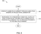
Figure 6 is amethod 600 for use with an electrical generator, according to examples disclosed herein. Themethod 600 may be used in conjunction with other examples, such as themain field circuit 350 illustrated inFigures 3 ,4 . -
Method 600 begins atblock 605, where the main field circuit conducts a main field current through a main field winding of the electrical generator. Atblock 615, and responsive to a predefined condition, the main field circuit couples at least a portion of the main field current into a counter-field winding that is arranged proximate to the main field winding. In one example, the predefined condition comprises a predefined load fault condition. In another example, the predefined condition comprises enabling a predefined field weakening operation of the electrical generator. - Coupling at least a portion of the main field current into the counter-field winding operates to reduce a magnitude of the main field current. In one example, coupling at least a portion of the main field current into the counter-field winding comprises operating a switch element to arrange the counter-field winding in parallel with the main field winding between a first leg and a second leg of a main field circuit of the electrical generator. In one example, a first inductance of the counter-field winding is substantially equal to a second inductance of the main field winding, and the entire amount of the main field current is coupled into the counter-field winding.
Method 600 ends following completion ofblock 615. - Further, the disclosure comprises examples according to the following clauses:
- Clause 1. A main field circuit of an electrical generator, the main field circuit comprising: a main field winding configured to conduct a main field current; a counter-field winding arranged proximate to the main field winding; and a switch element configured to selectively couple at least a portion of the main field current into the counter-field winding to reduce a magnitude of the main field current.
- Clause 2. The main field circuit of clause 1, wherein the switch element is configured to couple at least a portion of the main field current into the counter-field winding responsive to detecting a predefined load fault condition.
-
Clause 3. The main field circuit of any preceding clause, in particular clause 1, wherein a first inductance of the counter-field winding is substantially equal to a second inductance of the main field winding. - Clause 4. The main field circuit of any preceding clause, in particular clause 1, wherein the electrical generator comprises a rotor defining a plurality of slots, wherein each slot of the plurality of slots includes a respective portion of the main field winding and a respective portion of the counter-field winding.
- Clause 5. The main field circuit of any preceding clause, in particular clause 1, wherein coupling at least a portion of the main field current into the counter-field winding comprises arranging the counter-field winding in parallel with the main field winding between a first leg and a second leg of the main field circuit.
- Clause 6. The main field circuit of clause 5, wherein arranging the counter-field winding in parallel with the main field winding occurs responsive to determining that a voltage difference between the first leg and the second leg is less than a predetermined value.
- Clause 7. The main field circuit of clause 5 or 6, wherein the counter-field winding is included in a branch arranged between the first leg and the second leg, wherein a resistance of the branch is selected to provide a desired time constant of the main field circuit when the counter-field winding is arranged in parallel with the main field winding.
- Clause 8. The main field circuit of clause 7, wherein at least a portion of the branch is physically coupled with a rotor shaft of the electrical generator to transfer resistive heat away from the branch.
- Clause 9. A system comprising: an electrical generator comprising: a first rotor winding configured to conduct a main field current; a second rotor winding arranged proximate to the main field winding; a first switch element arranged in series with the second rotor winding; and a controller configured to operate the first switch element to selectively couple at least a portion of the main field current into the second rotor winding to reduce a magnitude of the main field current.
- Clause 10. The system of clause 9, wherein the controller is configured to operate the first switch element in a conducting state responsive to detecting a predefined load fault condition.
- Clause 11. The system of any preceding clause, in particular clause 10, further comprising: a second switch element, wherein the controller is further configured to operate the second switch element to selectively decouple an exciter armature current from being added into the main field winding.
- Clause 12. The system of any preceding clause, in particular clause 9, wherein a first inductance of the first rotor winding is substantially equal to a second inductance of the second rotor winding.
- Clause 13. The system of any preceding clause, in particular clause 9, wherein the electrical generator further comprises a rotor defining a plurality of slots, wherein each slot of the plurality of slots includes a respective portion of the first rotor winding and a respective portion of the second rotor winding.
- Clause 14. The system of any preceding clause, in particular clause 9, wherein coupling at least a portion of the main field current into the second rotor winding comprises arranging the second rotor winding in parallel with the first rotor winding between a first leg and a second leg of a main field circuit of the electrical generator.
- Clause 15. The system of clause 14, wherein arranging the second rotor winding in parallel with the first rotor winding occurs responsive to the controller determining that a voltage difference between the first leg and the second leg is less than a predetermined value.
- Clause 16. A method for use with an electrical generator, the method comprising: conducting a main field current through a main field winding of the electrical generator; and responsive to a predefined condition, coupling at least a portion of the main field current into a counter-field winding that is arranged proximate to the main field winding, wherein coupling at least a portion of the main field current into the counter-field winding operates to reduce a magnitude of the main field current.
- Clause 17. The method of clause 16, wherein the predefined condition comprises a predefined load fault condition.
- Clause 18. The method of any preceding clause, in particular clause 16, wherein the predefined condition comprises enabling a predefined field weakening operation of the electrical generator.
- Clause 19. The method of any preceding clause, in particular clause 16, wherein a first inductance of the counter-field winding is substantially equal to a second inductance of the main field winding.
-
Clause 20. The method of any preceding clause, in particular clause 16, wherein coupling at least a portion of the main field current into the counter-field winding comprises operating a switch element to arrange the counter-field winding in parallel with the main field winding between a first leg and a second leg of a main field circuit of the electrical generator. - In the preceding, reference is made to examples presented in this disclosure. However, the scope of the present disclosure is not limited to specific described examples. Instead, any combination of the described features and elements, whether related to different examples or not, is contemplated to implement and practice contemplated examples. Furthermore, although examples disclosed herein may achieve advantages over other possible solutions or over the prior art, whether or not a particular advantage is achieved by a given example is not limiting of the scope of the present disclosure. Thus, the preceding aspects, features, examples and advantages are merely illustrative and are not considered elements or limitations of the appended claims except where explicitly recited in a claim(s).
- The flowchart and block diagrams in the Figures illustrate the architecture, functionality and operation of possible implementations of systems, methods and computer program products according to various examples. In this regard, each block in the flowchart or block diagrams may represent a module, segment, or portion of code, which comprises one or more executable instructions for implementing the specified logical function(s). It should also be noted that, in some alternative implementations, the functions noted in the block may occur out of the order noted in the figures. For example, two blocks shown in succession may, in fact, be executed substantially concurrently, or the blocks may sometimes be executed in the reverse order, depending upon the functionality involved. It will also be noted that each block of the block diagrams and/or flowchart illustration, and combinations of blocks in the block diagrams and/or flowchart illustration, can be implemented by special purpose hardware-based systems that perform the specified functions or acts, or combinations of special purpose hardware and computer instructions.
- In view of the foregoing, the scope of the present disclosure is determined by the claims that follow.
Claims (13)
- A main field circuit (350) of an electrical generator (300, 400), the main field circuit comprising:a main field winding (160) configured to conduct a main field current;a counter-field winding (345) arranged proximate to the main field winding; anda switch element (320b) configured to selectively couple at least a portion of the main field current into the counter-field winding to reduce a magnitude of the main field current.
- The main field circuit of claim 1, wherein the switch element is configured to couple at least a portion of the main field current into the counter-field winding responsive to detecting a predefined load fault condition.
- The main field circuit of any preceding claim, wherein a first inductance of the counter-field winding is substantially equal to a second inductance of the main field winding.
- The main field circuit of any preceding claim, wherein the electrical generator comprises a rotor (105) defining a plurality of slots (505),
wherein each slot of the plurality of slots includes a respective portion (510) of the main field winding and a respective portion (515) of the counter-field winding. - The main field circuit of any preceding claim, wherein coupling at least a portion of the main field current into the counter-field winding comprises arranging the counter-field winding in parallel with the main field winding between a first leg (325) and a second leg (330) of the main field circuit.
- The main field circuit of claim 5, wherein arranging the counter-field winding in parallel with the main field winding occurs responsive to determining that a voltage difference between the first leg and the second leg is less than a predetermined value.
- The main field circuit of claim 5 or 6, wherein the counter-field winding is included in a branch (335) arranged between the first leg and the second leg, wherein a resistance of the branch is selected to provide a desired time constant of the main field circuit when the counter-field winding is arranged in parallel with the main field winding.
- The main field circuit of claim 7, wherein at least a portion of the branch is physically coupled with a rotor shaft of the electrical generator to transfer resistive heat away from the branch.
- A method (600) for use with an electrical generator (300, 400), the method comprising:conducting (605) a main field current through a main field winding (160) of the electrical generator; andresponsive to a predefined condition, coupling (615) at least a portion of the main field current into a counter-field winding (345) that is arranged proximate to the main field winding,wherein coupling at least a portion (510) of the main field current into the counter-field winding operates to reduce a magnitude of the main field current.
- The method of claim 9, wherein the predefined condition comprises a predefined load fault condition.
- The method of claim 9 or 10, wherein the predefined condition comprises enabling a predefined field weakening operation of the electrical generator.
- The method of any of claims 9 to 11, wherein a first inductance of the counter-field winding is substantially equal to a second inductance of the main field winding.
- The method of any of claims 9 to 12, wherein coupling at least a portion of the main field current into the counter-field winding comprises operating a switch element (320b) to arrange the counter-field winding in parallel with the main field winding between a first leg (325) and a second leg (330) of a main field circuit (350) of the electrical generator.
Applications Claiming Priority (1)
| Application Number | Priority Date | Filing Date | Title |
|---|---|---|---|
| US15/804,798 US10177698B1 (en) | 2017-11-06 | 2017-11-06 | Counter-field winding in electrical generator |
Publications (2)
| Publication Number | Publication Date |
|---|---|
| EP3480937A1 true EP3480937A1 (en) | 2019-05-08 |
| EP3480937B1 EP3480937B1 (en) | 2021-12-08 |
Family
ID=62951902
Family Applications (1)
| Application Number | Title | Priority Date | Filing Date |
|---|---|---|---|
| EP18183335.1A Active EP3480937B1 (en) | 2017-11-06 | 2018-07-13 | Counter-field winding in electrical generator |
Country Status (4)
| Country | Link |
|---|---|
| US (2) | US10177698B1 (en) |
| EP (1) | EP3480937B1 (en) |
| JP (1) | JP7244255B2 (en) |
| CN (1) | CN109756164A (en) |
Families Citing this family (6)
| Publication number | Priority date | Publication date | Assignee | Title |
|---|---|---|---|---|
| US11148819B2 (en) | 2019-01-23 | 2021-10-19 | H55 Sa | Battery module for electrically-driven aircraft |
| US11063323B2 (en) | 2019-01-23 | 2021-07-13 | H55 Sa | Battery module for electrically-driven aircraft |
| US11065979B1 (en) | 2017-04-05 | 2021-07-20 | H55 Sa | Aircraft monitoring system and method for electric or hybrid aircrafts |
| US10322824B1 (en) | 2018-01-25 | 2019-06-18 | H55 Sa | Construction and operation of electric or hybrid aircraft |
| US10177698B1 (en) * | 2017-11-06 | 2019-01-08 | The Boeing Company | Counter-field winding in electrical generator |
| FR3082069B1 (en) * | 2018-05-29 | 2020-05-01 | Safran | SYSTEM FOR SYNCHRONIZING COUPLED ENERGY SOURCES OF AN AIRCRAFT |
Citations (4)
| Publication number | Priority date | Publication date | Assignee | Title |
|---|---|---|---|---|
| GB253932A (en) * | 1925-06-22 | 1927-01-13 | Gen Electric | Method of controlling the excitation of dynamo electric machines |
| US2781486A (en) * | 1953-08-14 | 1957-02-12 | Leece Neville Co | Electrical generating systems |
| EP2779425A2 (en) * | 2013-03-15 | 2014-09-17 | Hamilton Sundstrand Corporation | EPGS architecture with multi-channel synchronous generator and common field regulated exciter |
| US20160141988A1 (en) * | 2014-11-17 | 2016-05-19 | The Boeing Company | System and Method For Generator Main Field Energy Extraction |
Family Cites Families (46)
| Publication number | Priority date | Publication date | Assignee | Title |
|---|---|---|---|---|
| US1374043A (en) * | 1917-01-27 | 1921-04-05 | Us Light & Heat Corp | System of electrical distribution |
| US1374041A (en) * | 1917-12-18 | 1921-04-05 | Us Light & Heat Corp | System of electrical distribution |
| US1475880A (en) * | 1920-05-21 | 1923-11-27 | Rickets William John | Controlling and regulating system for dynamos |
| US1988288A (en) * | 1929-12-30 | 1935-01-15 | Allis Chalmers Mfg Co | Dynamo-electric machine regulation |
| US2055057A (en) * | 1932-05-07 | 1936-09-22 | Eclipse Aviat Corp | Alternating current supply |
| US2053440A (en) * | 1933-07-12 | 1936-09-08 | Westinghouse Electric & Mfg Co | Motor control system |
| US2180700A (en) * | 1938-04-16 | 1939-11-21 | Air Reduction | Direct-current arc-welding generator |
| US2278632A (en) * | 1939-12-14 | 1942-04-07 | Cutler Hammer Inc | Generator control system |
| US2325407A (en) * | 1941-05-31 | 1943-07-27 | Gen Electric | Dynamoelectric machine |
| US2330993A (en) * | 1942-01-21 | 1943-10-05 | Cutler Hammer Inc | Motor-generator control system |
| US2386040A (en) * | 1942-09-28 | 1945-10-02 | Gen Electric | Electric control system |
| US2497492A (en) * | 1947-07-09 | 1950-02-14 | Electric Controller & Mfg Co | Control means for dynamic braking |
| US2568407A (en) * | 1949-12-10 | 1951-09-18 | Westinghouse Electric Corp | Excitation system |
| US2598124A (en) * | 1949-12-28 | 1952-05-27 | Fairbanks Morse & Co | Power plant regulation |
| US3142029A (en) * | 1960-08-22 | 1964-07-21 | Gen Electric | Shielding of foil wound electrical apparatus |
| US3250859A (en) * | 1962-12-31 | 1966-05-10 | American Telephone & Telegraph | Universal line concentrator |
| US3544881A (en) * | 1968-09-11 | 1970-12-01 | Gen Motors Corp | Transistor voltage and current regulating system for an alternating current generator |
| US3835363A (en) * | 1973-12-17 | 1974-09-10 | Gen Motors Corp | Motor vehicle power supply system |
| JPS5111124A (en) * | 1974-07-19 | 1976-01-29 | Hitachi Ltd | Chokuryudendokino kasokuboshisochi |
| DE2615117B2 (en) * | 1976-04-07 | 1978-07-20 | Siemens Ag, 1000 Berlin Und 8000 Muenchen | A brushless synchronous generator with constant voltage control and an overvoltage protection arrangement |
| US4496888A (en) * | 1977-12-08 | 1985-01-29 | Lucas Industries Limited | Control system for a d.c. motor |
| JPS5563600A (en) * | 1978-11-06 | 1980-05-13 | Komatsu Ltd | Car generator |
| DE3035819A1 (en) * | 1980-09-23 | 1982-05-06 | Robert Bosch Gmbh, 7000 Stuttgart | SELF-EXCITED ELECTRIC GENERATOR |
| JPS58162875A (en) * | 1982-03-23 | 1983-09-27 | Mitsubishi Electric Corp | Charge displaying and warning device |
| US4625160A (en) * | 1984-12-17 | 1986-11-25 | Sundstrand Corporation | Variable speed constant frequency generating system |
| US5645745A (en) * | 1994-09-02 | 1997-07-08 | Chrysler Corporation | Circuit and control method for electrically heating a catalyst |
| JPH1089809A (en) | 1996-09-18 | 1998-04-10 | Fuji Koki:Kk | Expansion valve |
| DE19845569A1 (en) | 1997-10-11 | 1999-04-15 | Bosch Gmbh Robert | Device and procedure especially for controlling 3-phase generator with rectifier bridge, for motor vehicle |
| US6239996B1 (en) * | 2000-01-24 | 2001-05-29 | Massachusetts Institute Of Technology | Dual output alternator system |
| JP3932876B2 (en) | 2001-12-06 | 2007-06-20 | 株式会社デンソー | AC generator for vehicles |
| US7106030B2 (en) | 2004-01-14 | 2006-09-12 | Vanner, Inc. | Field excitation for an alternator |
| US7154249B2 (en) | 2005-02-17 | 2006-12-26 | Teleflex Canada Incorporated | Energy discharge apparatus |
| GB2423652B (en) | 2005-02-24 | 2008-06-11 | Alstom | Exciter assemblies |
| US7276804B2 (en) | 2005-06-22 | 2007-10-02 | C.E. Niehoff & Co. | Voltage regulator with improved protection and warning system |
| GB0702253D0 (en) | 2007-02-06 | 2007-03-14 | Cummins Generator Technologies | Method of and apparatus for controlling excitation |
| US7719239B2 (en) | 2007-03-27 | 2010-05-18 | Honeywell International Inc. | Fast field discharge for generator over-voltage control |
| US7977910B2 (en) | 2007-04-20 | 2011-07-12 | Siemens Industry, Inc. | Method of starting a synchronous motor with a brushless DC exciter |
| US8030905B2 (en) | 2008-07-10 | 2011-10-04 | Honeywell International Inc. | Isolated generator control unit (GCU) |
| US8289005B2 (en) | 2008-09-30 | 2012-10-16 | C.E. Niehoff & Co. | Field transient suppression system and method |
| US8198871B2 (en) | 2009-01-08 | 2012-06-12 | Caterpillar Inc. | Time lag reduction circuit for alternating current generator and electric drive machine using same |
| FR2941695B1 (en) | 2009-02-04 | 2011-02-18 | Servier Lab | NOVEL PROCESS FOR THE SYNTHESIS OF IVABRADINE AND ITS SALTS OF ADDITION TO A PHARMACEUTICALLY ACCEPTABLE ACID |
| US8773080B2 (en) | 2010-12-16 | 2014-07-08 | Kohler Co. | Resonant commutation system for exciting a three-phase alternator |
| CN103609015A (en) | 2011-03-11 | 2014-02-26 | 布鲁萨电子公司 | Synchronous machine with switching element in the excitation circuit |
| WO2013079761A1 (en) | 2011-11-28 | 2013-06-06 | Abb Oy | Rotating electrical machine |
| US8975876B2 (en) | 2013-03-15 | 2015-03-10 | Hamilton Sunstrand Corporation | Method of controlling rotating main field converter |
| US10177698B1 (en) * | 2017-11-06 | 2019-01-08 | The Boeing Company | Counter-field winding in electrical generator |
-
2017
- 2017-11-06 US US15/804,798 patent/US10177698B1/en active Active
-
2018
- 2018-07-13 EP EP18183335.1A patent/EP3480937B1/en active Active
- 2018-08-03 CN CN201810875941.8A patent/CN109756164A/en active Pending
- 2018-11-05 JP JP2018207834A patent/JP7244255B2/en active Active
- 2018-12-04 US US16/208,792 patent/US10418926B2/en active Active
Patent Citations (4)
| Publication number | Priority date | Publication date | Assignee | Title |
|---|---|---|---|---|
| GB253932A (en) * | 1925-06-22 | 1927-01-13 | Gen Electric | Method of controlling the excitation of dynamo electric machines |
| US2781486A (en) * | 1953-08-14 | 1957-02-12 | Leece Neville Co | Electrical generating systems |
| EP2779425A2 (en) * | 2013-03-15 | 2014-09-17 | Hamilton Sundstrand Corporation | EPGS architecture with multi-channel synchronous generator and common field regulated exciter |
| US20160141988A1 (en) * | 2014-11-17 | 2016-05-19 | The Boeing Company | System and Method For Generator Main Field Energy Extraction |
Also Published As
| Publication number | Publication date |
|---|---|
| JP7244255B2 (en) | 2023-03-22 |
| BR102018015889A8 (en) | 2023-02-14 |
| JP2019110743A (en) | 2019-07-04 |
| BR102018015889A2 (en) | 2019-06-04 |
| EP3480937B1 (en) | 2021-12-08 |
| US10418926B2 (en) | 2019-09-17 |
| US10177698B1 (en) | 2019-01-08 |
| CN109756164A (en) | 2019-05-14 |
| US20190140570A1 (en) | 2019-05-09 |
Similar Documents
| Publication | Publication Date | Title |
|---|---|---|
| EP3480937B1 (en) | Counter-field winding in electrical generator | |
| JP5587432B2 (en) | Method and device for controlling a polyphase electrical machine | |
| JP6194113B2 (en) | Motor drive device | |
| US10320183B2 (en) | Control strategy of a dual lane fault tolerant permanent magnet motor to reduce drag torque under fault condition | |
| JP2009303298A (en) | Ac motor device | |
| US9203341B2 (en) | Switch arrangement | |
| EP2779379A2 (en) | Rotating diode assembly including overvoltage protection circuit | |
| CA2843376C (en) | Over voltage protection for electric machines | |
| CN113169679B (en) | Power conversion device | |
| US9564845B2 (en) | System and method for generator main field energy extraction | |
| JP6305495B1 (en) | Inverter control device and inverter control method | |
| US11128249B2 (en) | Solid state phase isolation of multi-phase motors | |
| US8884590B2 (en) | Electricity generation device and permanent-magnet electric generator | |
| TWI505625B (en) | Power conversion system and its control method | |
| BR102018015889B1 (en) | ELECTRIC GENERATOR MAIN FIELD CIRCUIT AND METHOD FOR USE WITH ELECTRIC GENERATOR | |
| JP4822138B2 (en) | Power generation system and operation method thereof | |
| Wu et al. | Comparative study of remediation methods for open circuit fault in a novel symmetric six-phase fault-tolerant PM machine drives for EVs | |
| JP2007151288A (en) | Alternating-current motor drive system | |
| JP2013070564A (en) | Alternator and rectifier |
Legal Events
| Date | Code | Title | Description |
|---|---|---|---|
| PUAI | Public reference made under article 153(3) epc to a published international application that has entered the european phase |
Free format text: ORIGINAL CODE: 0009012 |
|
| STAA | Information on the status of an ep patent application or granted ep patent |
Free format text: STATUS: REQUEST FOR EXAMINATION WAS MADE |
|
| STAA | Information on the status of an ep patent application or granted ep patent |
Free format text: STATUS: REQUEST FOR EXAMINATION WAS MADE |
|
| 17P | Request for examination filed |
Effective date: 20180713 |
|
| AK | Designated contracting states |
Kind code of ref document: A1 Designated state(s): AL AT BE BG CH CY CZ DE DK EE ES FI FR GB GR HR HU IE IS IT LI LT LU LV MC MK MT NL NO PL PT RO RS SE SI SK SM TR |
|
| AX | Request for extension of the european patent |
Extension state: BA ME |
|
| STAA | Information on the status of an ep patent application or granted ep patent |
Free format text: STATUS: EXAMINATION IS IN PROGRESS |
|
| 17Q | First examination report despatched |
Effective date: 20210223 |
|
| GRAP | Despatch of communication of intention to grant a patent |
Free format text: ORIGINAL CODE: EPIDOSNIGR1 |
|
| STAA | Information on the status of an ep patent application or granted ep patent |
Free format text: STATUS: GRANT OF PATENT IS INTENDED |
|
| RIC1 | Information provided on ipc code assigned before grant |
Ipc: H02P 9/10 20060101AFI20210616BHEP Ipc: H02P 29/024 20160101ALI20210616BHEP Ipc: H02K 19/26 20060101ALI20210616BHEP Ipc: H02K 3/20 20060101ALN20210616BHEP |
|
| INTG | Intention to grant announced |
Effective date: 20210702 |
|
| GRAS | Grant fee paid |
Free format text: ORIGINAL CODE: EPIDOSNIGR3 |
|
| GRAA | (expected) grant |
Free format text: ORIGINAL CODE: 0009210 |
|
| STAA | Information on the status of an ep patent application or granted ep patent |
Free format text: STATUS: THE PATENT HAS BEEN GRANTED |
|
| AK | Designated contracting states |
Kind code of ref document: B1 Designated state(s): AL AT BE BG CH CY CZ DE DK EE ES FI FR GB GR HR HU IE IS IT LI LT LU LV MC MK MT NL NO PL PT RO RS SE SI SK SM TR |
|
| REG | Reference to a national code |
Ref country code: GB Ref legal event code: FG4D |
|
| REG | Reference to a national code |
Ref country code: AT Ref legal event code: REF Ref document number: 1454508 Country of ref document: AT Kind code of ref document: T Effective date: 20211215 Ref country code: CH Ref legal event code: EP |
|
| REG | Reference to a national code |
Ref country code: DE Ref legal event code: R096 Ref document number: 602018027784 Country of ref document: DE |
|
| REG | Reference to a national code |
Ref country code: IE Ref legal event code: FG4D |
|
| REG | Reference to a national code |
Ref country code: LT Ref legal event code: MG9D |
|
| REG | Reference to a national code |
Ref country code: NL Ref legal event code: MP Effective date: 20211208 |
|
| PG25 | Lapsed in a contracting state [announced via postgrant information from national office to epo] |
Ref country code: RS Free format text: LAPSE BECAUSE OF FAILURE TO SUBMIT A TRANSLATION OF THE DESCRIPTION OR TO PAY THE FEE WITHIN THE PRESCRIBED TIME-LIMIT Effective date: 20211208 Ref country code: LT Free format text: LAPSE BECAUSE OF FAILURE TO SUBMIT A TRANSLATION OF THE DESCRIPTION OR TO PAY THE FEE WITHIN THE PRESCRIBED TIME-LIMIT Effective date: 20211208 Ref country code: FI Free format text: LAPSE BECAUSE OF FAILURE TO SUBMIT A TRANSLATION OF THE DESCRIPTION OR TO PAY THE FEE WITHIN THE PRESCRIBED TIME-LIMIT Effective date: 20211208 Ref country code: BG Free format text: LAPSE BECAUSE OF FAILURE TO SUBMIT A TRANSLATION OF THE DESCRIPTION OR TO PAY THE FEE WITHIN THE PRESCRIBED TIME-LIMIT Effective date: 20220308 |
|
| REG | Reference to a national code |
Ref country code: AT Ref legal event code: MK05 Ref document number: 1454508 Country of ref document: AT Kind code of ref document: T Effective date: 20211208 |
|
| PG25 | Lapsed in a contracting state [announced via postgrant information from national office to epo] |
Ref country code: SE Free format text: LAPSE BECAUSE OF FAILURE TO SUBMIT A TRANSLATION OF THE DESCRIPTION OR TO PAY THE FEE WITHIN THE PRESCRIBED TIME-LIMIT Effective date: 20211208 Ref country code: NO Free format text: LAPSE BECAUSE OF FAILURE TO SUBMIT A TRANSLATION OF THE DESCRIPTION OR TO PAY THE FEE WITHIN THE PRESCRIBED TIME-LIMIT Effective date: 20220308 Ref country code: LV Free format text: LAPSE BECAUSE OF FAILURE TO SUBMIT A TRANSLATION OF THE DESCRIPTION OR TO PAY THE FEE WITHIN THE PRESCRIBED TIME-LIMIT Effective date: 20211208 Ref country code: HR Free format text: LAPSE BECAUSE OF FAILURE TO SUBMIT A TRANSLATION OF THE DESCRIPTION OR TO PAY THE FEE WITHIN THE PRESCRIBED TIME-LIMIT Effective date: 20211208 Ref country code: GR Free format text: LAPSE BECAUSE OF FAILURE TO SUBMIT A TRANSLATION OF THE DESCRIPTION OR TO PAY THE FEE WITHIN THE PRESCRIBED TIME-LIMIT Effective date: 20220309 Ref country code: ES Free format text: LAPSE BECAUSE OF FAILURE TO SUBMIT A TRANSLATION OF THE DESCRIPTION OR TO PAY THE FEE WITHIN THE PRESCRIBED TIME-LIMIT Effective date: 20211208 |
|
| PG25 | Lapsed in a contracting state [announced via postgrant information from national office to epo] |
Ref country code: NL Free format text: LAPSE BECAUSE OF FAILURE TO SUBMIT A TRANSLATION OF THE DESCRIPTION OR TO PAY THE FEE WITHIN THE PRESCRIBED TIME-LIMIT Effective date: 20211208 |
|
| PG25 | Lapsed in a contracting state [announced via postgrant information from national office to epo] |
Ref country code: SM Free format text: LAPSE BECAUSE OF FAILURE TO SUBMIT A TRANSLATION OF THE DESCRIPTION OR TO PAY THE FEE WITHIN THE PRESCRIBED TIME-LIMIT Effective date: 20211208 Ref country code: SK Free format text: LAPSE BECAUSE OF FAILURE TO SUBMIT A TRANSLATION OF THE DESCRIPTION OR TO PAY THE FEE WITHIN THE PRESCRIBED TIME-LIMIT Effective date: 20211208 Ref country code: RO Free format text: LAPSE BECAUSE OF FAILURE TO SUBMIT A TRANSLATION OF THE DESCRIPTION OR TO PAY THE FEE WITHIN THE PRESCRIBED TIME-LIMIT Effective date: 20211208 Ref country code: PT Free format text: LAPSE BECAUSE OF FAILURE TO SUBMIT A TRANSLATION OF THE DESCRIPTION OR TO PAY THE FEE WITHIN THE PRESCRIBED TIME-LIMIT Effective date: 20220408 Ref country code: EE Free format text: LAPSE BECAUSE OF FAILURE TO SUBMIT A TRANSLATION OF THE DESCRIPTION OR TO PAY THE FEE WITHIN THE PRESCRIBED TIME-LIMIT Effective date: 20211208 Ref country code: CZ Free format text: LAPSE BECAUSE OF FAILURE TO SUBMIT A TRANSLATION OF THE DESCRIPTION OR TO PAY THE FEE WITHIN THE PRESCRIBED TIME-LIMIT Effective date: 20211208 |
|
| PG25 | Lapsed in a contracting state [announced via postgrant information from national office to epo] |
Ref country code: PL Free format text: LAPSE BECAUSE OF FAILURE TO SUBMIT A TRANSLATION OF THE DESCRIPTION OR TO PAY THE FEE WITHIN THE PRESCRIBED TIME-LIMIT Effective date: 20211208 Ref country code: AT Free format text: LAPSE BECAUSE OF FAILURE TO SUBMIT A TRANSLATION OF THE DESCRIPTION OR TO PAY THE FEE WITHIN THE PRESCRIBED TIME-LIMIT Effective date: 20211208 |
|
| REG | Reference to a national code |
Ref country code: DE Ref legal event code: R097 Ref document number: 602018027784 Country of ref document: DE |
|
| PG25 | Lapsed in a contracting state [announced via postgrant information from national office to epo] |
Ref country code: IS Free format text: LAPSE BECAUSE OF FAILURE TO SUBMIT A TRANSLATION OF THE DESCRIPTION OR TO PAY THE FEE WITHIN THE PRESCRIBED TIME-LIMIT Effective date: 20220408 |
|
| PLBE | No opposition filed within time limit |
Free format text: ORIGINAL CODE: 0009261 |
|
| STAA | Information on the status of an ep patent application or granted ep patent |
Free format text: STATUS: NO OPPOSITION FILED WITHIN TIME LIMIT |
|
| PG25 | Lapsed in a contracting state [announced via postgrant information from national office to epo] |
Ref country code: DK Free format text: LAPSE BECAUSE OF FAILURE TO SUBMIT A TRANSLATION OF THE DESCRIPTION OR TO PAY THE FEE WITHIN THE PRESCRIBED TIME-LIMIT Effective date: 20211208 Ref country code: AL Free format text: LAPSE BECAUSE OF FAILURE TO SUBMIT A TRANSLATION OF THE DESCRIPTION OR TO PAY THE FEE WITHIN THE PRESCRIBED TIME-LIMIT Effective date: 20211208 |
|
| 26N | No opposition filed |
Effective date: 20220909 |
|
| PG25 | Lapsed in a contracting state [announced via postgrant information from national office to epo] |
Ref country code: SI Free format text: LAPSE BECAUSE OF FAILURE TO SUBMIT A TRANSLATION OF THE DESCRIPTION OR TO PAY THE FEE WITHIN THE PRESCRIBED TIME-LIMIT Effective date: 20211208 |
|
| PG25 | Lapsed in a contracting state [announced via postgrant information from national office to epo] |
Ref country code: MC Free format text: LAPSE BECAUSE OF FAILURE TO SUBMIT A TRANSLATION OF THE DESCRIPTION OR TO PAY THE FEE WITHIN THE PRESCRIBED TIME-LIMIT Effective date: 20211208 |
|
| REG | Reference to a national code |
Ref country code: CH Ref legal event code: PL |
|
| REG | Reference to a national code |
Ref country code: BE Ref legal event code: MM Effective date: 20220731 |
|
| PG25 | Lapsed in a contracting state [announced via postgrant information from national office to epo] |
Ref country code: LU Free format text: LAPSE BECAUSE OF NON-PAYMENT OF DUE FEES Effective date: 20220713 Ref country code: LI Free format text: LAPSE BECAUSE OF NON-PAYMENT OF DUE FEES Effective date: 20220731 Ref country code: CH Free format text: LAPSE BECAUSE OF NON-PAYMENT OF DUE FEES Effective date: 20220731 |
|
| PG25 | Lapsed in a contracting state [announced via postgrant information from national office to epo] |
Ref country code: IT Free format text: LAPSE BECAUSE OF FAILURE TO SUBMIT A TRANSLATION OF THE DESCRIPTION OR TO PAY THE FEE WITHIN THE PRESCRIBED TIME-LIMIT Effective date: 20211208 Ref country code: BE Free format text: LAPSE BECAUSE OF NON-PAYMENT OF DUE FEES Effective date: 20220731 |
|
| P01 | Opt-out of the competence of the unified patent court (upc) registered |
Effective date: 20230516 |
|
| PG25 | Lapsed in a contracting state [announced via postgrant information from national office to epo] |
Ref country code: IE Free format text: LAPSE BECAUSE OF NON-PAYMENT OF DUE FEES Effective date: 20220713 |
|
| PGFP | Annual fee paid to national office [announced via postgrant information from national office to epo] |
Ref country code: GB Payment date: 20230727 Year of fee payment: 6 |
|
| PGFP | Annual fee paid to national office [announced via postgrant information from national office to epo] |
Ref country code: FR Payment date: 20230725 Year of fee payment: 6 Ref country code: DE Payment date: 20230727 Year of fee payment: 6 |
|
| PG25 | Lapsed in a contracting state [announced via postgrant information from national office to epo] |
Ref country code: HU Free format text: LAPSE BECAUSE OF FAILURE TO SUBMIT A TRANSLATION OF THE DESCRIPTION OR TO PAY THE FEE WITHIN THE PRESCRIBED TIME-LIMIT; INVALID AB INITIO Effective date: 20180713 |