EP3480936B1 - Magnetic suspension power system - Google Patents
Magnetic suspension power system Download PDFInfo
- Publication number
- EP3480936B1 EP3480936B1 EP16906970.5A EP16906970A EP3480936B1 EP 3480936 B1 EP3480936 B1 EP 3480936B1 EP 16906970 A EP16906970 A EP 16906970A EP 3480936 B1 EP3480936 B1 EP 3480936B1
- Authority
- EP
- European Patent Office
- Prior art keywords
- wheel hub
- magnetic
- driver shaft
- power system
- magnetic levitation
- Prior art date
- Legal status (The legal status is an assumption and is not a legal conclusion. Google has not performed a legal analysis and makes no representation as to the accuracy of the status listed.)
- Active
Links
- 239000000725 suspension Substances 0.000 title 1
- 238000005339 levitation Methods 0.000 claims description 151
- 230000003993 interaction Effects 0.000 claims description 13
- 230000008859 change Effects 0.000 claims description 10
- 230000033001 locomotion Effects 0.000 claims description 9
- 238000005259 measurement Methods 0.000 claims description 4
- 230000005540 biological transmission Effects 0.000 description 9
- 238000010586 diagram Methods 0.000 description 7
- 238000013016 damping Methods 0.000 description 3
- 238000000034 method Methods 0.000 description 3
- 230000008569 process Effects 0.000 description 3
- 238000003915 air pollution Methods 0.000 description 2
- 238000006243 chemical reaction Methods 0.000 description 2
- 238000002485 combustion reaction Methods 0.000 description 2
- 208000031872 Body Remains Diseases 0.000 description 1
- 230000001419 dependent effect Effects 0.000 description 1
- 238000005516 engineering process Methods 0.000 description 1
- 238000003912 environmental pollution Methods 0.000 description 1
- 239000000446 fuel Substances 0.000 description 1
- 230000005484 gravity Effects 0.000 description 1
Images


Classifications
-
- B—PERFORMING OPERATIONS; TRANSPORTING
- B60—VEHICLES IN GENERAL
- B60L—PROPULSION OF ELECTRICALLY-PROPELLED VEHICLES; SUPPLYING ELECTRIC POWER FOR AUXILIARY EQUIPMENT OF ELECTRICALLY-PROPELLED VEHICLES; ELECTRODYNAMIC BRAKE SYSTEMS FOR VEHICLES IN GENERAL; MAGNETIC SUSPENSION OR LEVITATION FOR VEHICLES; MONITORING OPERATING VARIABLES OF ELECTRICALLY-PROPELLED VEHICLES; ELECTRIC SAFETY DEVICES FOR ELECTRICALLY-PROPELLED VEHICLES
- B60L13/00—Electric propulsion for monorail vehicles, suspension vehicles or rack railways; Magnetic suspension or levitation for vehicles
- B60L13/04—Magnetic suspension or levitation for vehicles
-
- F—MECHANICAL ENGINEERING; LIGHTING; HEATING; WEAPONS; BLASTING
- F16—ENGINEERING ELEMENTS AND UNITS; GENERAL MEASURES FOR PRODUCING AND MAINTAINING EFFECTIVE FUNCTIONING OF MACHINES OR INSTALLATIONS; THERMAL INSULATION IN GENERAL
- F16C—SHAFTS; FLEXIBLE SHAFTS; ELEMENTS OR CRANKSHAFT MECHANISMS; ROTARY BODIES OTHER THAN GEARING ELEMENTS; BEARINGS
- F16C32/00—Bearings not otherwise provided for
- F16C32/04—Bearings not otherwise provided for using magnetic or electric supporting means
- F16C32/0406—Magnetic bearings
- F16C32/044—Active magnetic bearings
- F16C32/0474—Active magnetic bearings for rotary movement
- F16C32/0489—Active magnetic bearings for rotary movement with active support of five degrees of freedom, e.g. two radial magnetic bearings combined with an axial bearing
-
- B—PERFORMING OPERATIONS; TRANSPORTING
- B60—VEHICLES IN GENERAL
- B60L—PROPULSION OF ELECTRICALLY-PROPELLED VEHICLES; SUPPLYING ELECTRIC POWER FOR AUXILIARY EQUIPMENT OF ELECTRICALLY-PROPELLED VEHICLES; ELECTRODYNAMIC BRAKE SYSTEMS FOR VEHICLES IN GENERAL; MAGNETIC SUSPENSION OR LEVITATION FOR VEHICLES; MONITORING OPERATING VARIABLES OF ELECTRICALLY-PROPELLED VEHICLES; ELECTRIC SAFETY DEVICES FOR ELECTRICALLY-PROPELLED VEHICLES
- B60L13/00—Electric propulsion for monorail vehicles, suspension vehicles or rack railways; Magnetic suspension or levitation for vehicles
- B60L13/04—Magnetic suspension or levitation for vehicles
- B60L13/06—Means to sense or control vehicle position or attitude with respect to railway
- B60L13/08—Means to sense or control vehicle position or attitude with respect to railway for the lateral position
-
- B—PERFORMING OPERATIONS; TRANSPORTING
- B60—VEHICLES IN GENERAL
- B60B—VEHICLE WHEELS; CASTORS; AXLES FOR WHEELS OR CASTORS; INCREASING WHEEL ADHESION
- B60B19/00—Wheels not otherwise provided for or having characteristics specified in one of the subgroups of this group
- B60B19/006—Magnetic wheels
-
- B—PERFORMING OPERATIONS; TRANSPORTING
- B60—VEHICLES IN GENERAL
- B60K—ARRANGEMENT OR MOUNTING OF PROPULSION UNITS OR OF TRANSMISSIONS IN VEHICLES; ARRANGEMENT OR MOUNTING OF PLURAL DIVERSE PRIME-MOVERS IN VEHICLES; AUXILIARY DRIVES FOR VEHICLES; INSTRUMENTATION OR DASHBOARDS FOR VEHICLES; ARRANGEMENTS IN CONNECTION WITH COOLING, AIR INTAKE, GAS EXHAUST OR FUEL SUPPLY OF PROPULSION UNITS IN VEHICLES
- B60K1/00—Arrangement or mounting of electrical propulsion units
-
- B—PERFORMING OPERATIONS; TRANSPORTING
- B60—VEHICLES IN GENERAL
- B60K—ARRANGEMENT OR MOUNTING OF PROPULSION UNITS OR OF TRANSMISSIONS IN VEHICLES; ARRANGEMENT OR MOUNTING OF PLURAL DIVERSE PRIME-MOVERS IN VEHICLES; AUXILIARY DRIVES FOR VEHICLES; INSTRUMENTATION OR DASHBOARDS FOR VEHICLES; ARRANGEMENTS IN CONNECTION WITH COOLING, AIR INTAKE, GAS EXHAUST OR FUEL SUPPLY OF PROPULSION UNITS IN VEHICLES
- B60K7/00—Disposition of motor in, or adjacent to, traction wheel
- B60K7/0007—Disposition of motor in, or adjacent to, traction wheel the motor being electric
-
- B—PERFORMING OPERATIONS; TRANSPORTING
- B60—VEHICLES IN GENERAL
- B60K—ARRANGEMENT OR MOUNTING OF PROPULSION UNITS OR OF TRANSMISSIONS IN VEHICLES; ARRANGEMENT OR MOUNTING OF PLURAL DIVERSE PRIME-MOVERS IN VEHICLES; AUXILIARY DRIVES FOR VEHICLES; INSTRUMENTATION OR DASHBOARDS FOR VEHICLES; ARRANGEMENTS IN CONNECTION WITH COOLING, AIR INTAKE, GAS EXHAUST OR FUEL SUPPLY OF PROPULSION UNITS IN VEHICLES
- B60K8/00—Arrangement or mounting of propulsion units not provided for in one of the preceding main groups
-
- B—PERFORMING OPERATIONS; TRANSPORTING
- B60—VEHICLES IN GENERAL
- B60L—PROPULSION OF ELECTRICALLY-PROPELLED VEHICLES; SUPPLYING ELECTRIC POWER FOR AUXILIARY EQUIPMENT OF ELECTRICALLY-PROPELLED VEHICLES; ELECTRODYNAMIC BRAKE SYSTEMS FOR VEHICLES IN GENERAL; MAGNETIC SUSPENSION OR LEVITATION FOR VEHICLES; MONITORING OPERATING VARIABLES OF ELECTRICALLY-PROPELLED VEHICLES; ELECTRIC SAFETY DEVICES FOR ELECTRICALLY-PROPELLED VEHICLES
- B60L13/00—Electric propulsion for monorail vehicles, suspension vehicles or rack railways; Magnetic suspension or levitation for vehicles
- B60L13/10—Combination of electric propulsion and magnetic suspension or levitation
-
- H—ELECTRICITY
- H02—GENERATION; CONVERSION OR DISTRIBUTION OF ELECTRIC POWER
- H02K—DYNAMO-ELECTRIC MACHINES
- H02K7/00—Arrangements for handling mechanical energy structurally associated with dynamo-electric machines, e.g. structural association with mechanical driving motors or auxiliary dynamo-electric machines
- H02K7/006—Structural association of a motor or generator with the drive train of a motor vehicle
-
- H—ELECTRICITY
- H02—GENERATION; CONVERSION OR DISTRIBUTION OF ELECTRIC POWER
- H02K—DYNAMO-ELECTRIC MACHINES
- H02K7/00—Arrangements for handling mechanical energy structurally associated with dynamo-electric machines, e.g. structural association with mechanical driving motors or auxiliary dynamo-electric machines
- H02K7/08—Structural association with bearings
- H02K7/09—Structural association with bearings with magnetic bearings
-
- H—ELECTRICITY
- H02—GENERATION; CONVERSION OR DISTRIBUTION OF ELECTRIC POWER
- H02K—DYNAMO-ELECTRIC MACHINES
- H02K7/00—Arrangements for handling mechanical energy structurally associated with dynamo-electric machines, e.g. structural association with mechanical driving motors or auxiliary dynamo-electric machines
- H02K7/18—Structural association of electric generators with mechanical driving motors, e.g. with turbines
- H02K7/1807—Rotary generators
- H02K7/1846—Rotary generators structurally associated with wheels or associated parts
-
- H—ELECTRICITY
- H02—GENERATION; CONVERSION OR DISTRIBUTION OF ELECTRIC POWER
- H02N—ELECTRIC MACHINES NOT OTHERWISE PROVIDED FOR
- H02N15/00—Holding or levitation devices using magnetic attraction or repulsion, not otherwise provided for
-
- B—PERFORMING OPERATIONS; TRANSPORTING
- B60—VEHICLES IN GENERAL
- B60B—VEHICLE WHEELS; CASTORS; AXLES FOR WHEELS OR CASTORS; INCREASING WHEEL ADHESION
- B60B21/00—Rims
- B60B21/02—Rims characterised by transverse section
- B60B21/021—Rims characterised by transverse section with inwardly directed flanges, i.e. the tyre-seat being reversed
-
- B—PERFORMING OPERATIONS; TRANSPORTING
- B60—VEHICLES IN GENERAL
- B60B—VEHICLE WHEELS; CASTORS; AXLES FOR WHEELS OR CASTORS; INCREASING WHEEL ADHESION
- B60B2900/00—Purpose of invention
- B60B2900/90—Providing or changing
- B60B2900/931—Magnetic effects
-
- B—PERFORMING OPERATIONS; TRANSPORTING
- B60—VEHICLES IN GENERAL
- B60L—PROPULSION OF ELECTRICALLY-PROPELLED VEHICLES; SUPPLYING ELECTRIC POWER FOR AUXILIARY EQUIPMENT OF ELECTRICALLY-PROPELLED VEHICLES; ELECTRODYNAMIC BRAKE SYSTEMS FOR VEHICLES IN GENERAL; MAGNETIC SUSPENSION OR LEVITATION FOR VEHICLES; MONITORING OPERATING VARIABLES OF ELECTRICALLY-PROPELLED VEHICLES; ELECTRIC SAFETY DEVICES FOR ELECTRICALLY-PROPELLED VEHICLES
- B60L2200/00—Type of vehicles
- B60L2200/26—Rail vehicles
-
- F—MECHANICAL ENGINEERING; LIGHTING; HEATING; WEAPONS; BLASTING
- F16—ENGINEERING ELEMENTS AND UNITS; GENERAL MEASURES FOR PRODUCING AND MAINTAINING EFFECTIVE FUNCTIONING OF MACHINES OR INSTALLATIONS; THERMAL INSULATION IN GENERAL
- F16C—SHAFTS; FLEXIBLE SHAFTS; ELEMENTS OR CRANKSHAFT MECHANISMS; ROTARY BODIES OTHER THAN GEARING ELEMENTS; BEARINGS
- F16C2326/00—Articles relating to transporting
- F16C2326/01—Parts of vehicles in general
- F16C2326/02—Wheel hubs or castors
-
- F—MECHANICAL ENGINEERING; LIGHTING; HEATING; WEAPONS; BLASTING
- F16—ENGINEERING ELEMENTS AND UNITS; GENERAL MEASURES FOR PRODUCING AND MAINTAINING EFFECTIVE FUNCTIONING OF MACHINES OR INSTALLATIONS; THERMAL INSULATION IN GENERAL
- F16C—SHAFTS; FLEXIBLE SHAFTS; ELEMENTS OR CRANKSHAFT MECHANISMS; ROTARY BODIES OTHER THAN GEARING ELEMENTS; BEARINGS
- F16C2380/00—Electrical apparatus
- F16C2380/26—Dynamo-electric machines or combinations therewith, e.g. electro-motors and generators
Definitions
- the present invention relates to a magnetic levitation power system.
- a power system of an automobile in a prior art is taken as an example for illustration below.
- the automobile may be divided into: a steam-powered automobile, an internal combustion engine (ICE) automobile and an electric motor automobile.
- ICE internal combustion engine
- the mainstream automobile in the market today is still an ICE automobile, the engine of which is powered by fuel combustion.
- pure electric automobiles have gradually become the mainstream trend of future development.
- the generation of the motive power of the automobile power system has always relied on the engine.
- Current automobile power system refers to a whole mechanical configuration process of transferring the power generated by the engine through a series of power transmissions and finally to the wheels.
- the engine is actually a rotating of the crankshaft, one end of the crankshaft is fixedly connected to a flywheel, and the flywheel cooperates with a clutch to control a connection between the flywheel and a transmission.
- the power continues to be transmitted through a cardan joint and a drive shaft to a differential, and then the power is transmitted to retarder on both sides of the wheels after being averaged by the differential, and then the power is transmitted through a hyperbolic gear of the retarder to the wheels.
- the technical problems described below mainly exist in the automotive power system.
- the first problem is that the hardware cost is high as the structural components needs to include an engine, a transmission, a differential and a damping apparatus.
- the second problem is that non-renewable energy needs to be consumed.
- the third problem is that environmental pollution is likely to be caused.
- the fourth problem is that the shaft wears seriously, and energy loss is large.
- JP 2013 147213 A discloses the features of the preamble of claim 1 and relates to a vehicle drive apparatus which can reduce resistance of a bearing part where a wheel is supported by an axle, and allow the wheel to rotate readily at a high speed.
- US 2015/145363 A1 relates to an active magnetic wheel bearing including at least two electromagnetic units arranged to support a wheel hub flange of a vehicle within a bearing outer ring.
- the present invention develops a magnetic levitation power system according to independent claim 1 whereas various improvements thereto are recited in the dependent claims.
- a magnetic levitation power system is disposed on a wheel hub and a driver shaft and includes:
- driver shaft is not self-rotating.
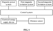
- the magnetic levitation power system includes an electrical energy supply device for powering the magnetic power system, the first magnetic levitation system and the second magnetic levitation system, where an output current of the electrical energy supply device is adjusted for changing a direction of a power provided by the magnetic power system, a magnitude of the power provided by the magnetic power system, and/or a levitation distance between the wheel hub and the driver shaft.
- the magnetic levitation power system includes a distance sensor disposed on the driver shaft and/or the wheel hub for measuring the levitation distance between the wheel hub and the driver shaft.
- the magnetic levitation power system further includes a control system connected to the electrical energy supply device and the distance sensor, where the control system is configured to adjust the output current of the electrical energy supply device according to measurement data of the distance sensor so that the levitation distance between the wheel hub and the driver shaft is maintained at a safe levitation distance; and the control system is further configured to adjust the output current of the electrical energy supply device to change the magnitude and/or the direction of the power provided by the magnetic power system when an object to which the magnetic levitation power system is applied has a speed and/or direction change demand.
- the magnetic power system includes:
- the first magnetic levitation system includes:
- the second magnetic levitation system includes:
- At least one of the magnetic power systems, at least one of the first magnetic levitation systems, and/or at least one of the second magnetic levitation systems are provided.
- the magnetic levitation power system provided by the present invention may be used to solve the problems of high hardware costs, low energy utilization rate, environmentally harmful characteristics, etc. of the existing automobile power system, and can abandon structural components of the existing automobile, such as an engine, a transmission, a differential, and a damping apparatus, and therefore hardware costs are reduced, losses in the energy conversion process are reduced, and air pollution from exhaust emissions is avoided.
- FIG. 1 is a structural block diagram of a magnetic levitation power system provided by the present invention.
- FIG. 2 is a structural diagram of a magnetic levitation power system according to embodiment 1 of the present invention, specifically, a sectional view of a single wheel hub 2 and a driver shaft 1. As shown in FIGS.
- the magnetic levitation power system is provided on the wheel hub 2 and the driver shaft 1 and includes: a magnetic power system a disposed on the wheel hub 2 and the driver shaft 1, where the magnetic power system a is configured to generate a power capable of enabling a movement of the wheel hub 2 through an interaction of magnetic fields between the wheel hub 2 and the driver shaft 1; a first magnetic levitation system b disposed on the wheel hub 2 and the driver shaft 1, where the first magnetic levitation system b is capable of enabling the wheel hub 2 and the driver shaft 1 to be in a levitation state within a circumferential extent of 360 degrees with the wheel hub 2 being opposite to the driver shaft 1through the interaction of the magnetic fields between the wheel hub 2 and the driver shaft 1, and further the driver shaft 1 is levitated at a distance from the circumferential direction of the wheel hub 2; and a second magnetic levitation system c disposed on the wheel hub 2 and the driver shaft 1, where the second magnetic levitation system c is capable of enabling the wheel hub 2
- the magnetic power system a, the first magnetic levitation system b and the second magnetic levitation system c are disposed at different locations of the wheel hub 2 and the driver shaft 1.
- the wheel hub 2 includes: an inner annular ring of the wheel hub 21, an outer annular ring of the wheel hub 22, and a wheel hub connecting portion 23 disposed between the inner annular ring of the wheel hub 21 and the outer annular ring of the wheel hub 22, where the inner annular ring of the wheel hub 21 and the outer annular ring of the wheel hub 22 are connected by the wheel hub connecting portion 23 and a space portion 10 is formed between the inner annular ring of the wheel hub 21, the outer annular ring of the wheel hub 22 and the wheel hub connecting portion 23.
- the driver shaft includes: a straight shaft 11, a driver shaft annular ring 12 centered around the straight shaft 11 and a driver shaft connecting portion 13 disposed between the driver shaft annular ring 12 and the straight shaft 11, where the driver shaft annular ring 12 is connected to the straight shaft 11 through the driver shaft connecting portion 13 and disposed in the space portion 10.
- the magnetic power system a is disposed on an inner side of the outer annular ring of the wheel hub 22 and on an outer side of driver shaft annular ring 12.
- the magnetic power system a includes: a rotor 4 disposed on an inner circumference of the outer annular ring of the wheel hub 22; and a stator 3 disposed on an outer circumference of the driver shaft annular ring 12.
- the first magnetic levitation system b is disposed on an outer side of the inner annular ring of the wheel hub 21 and an inner side of the driver shaft annular ring 12.
- the first magnetic levitation system b includes: a first permanent magnet component 8 disposed on an outer circumference of the inner annular ring of the wheel hub 21; and a first electromagnetic component 7 disposed on an inner circumference of the driver shaft annular ring 12 and disposed opposite to the first permanent magnet component 8.
- multiple first permanent magnet components 8 and multiple first electromagnetic components 7 are provided, and each of the multiple first electromagnetic components 7 may be disposed opposite to a respective one of the multiple first permanent magnet components 8.
- the second magnetic levitation system c is disposed on a side wall of the inner annular ring of the wheel hub 21 and on the driver shaft connecting portion 13.
- the second magnetic levitation system c includes: a second permanent magnet component 6 disposed on the side wall of the inner annular ring of the wheel hub 21; and a second electromagnetic component 5 disposed on the driver shaft connecting portion 13 and disposed opposite to the second permanent magnet component 6.
- a second permanent magnet component 6 disposed on the side wall of the inner annular ring of the wheel hub 21
- a second electromagnetic component 5 disposed on the driver shaft connecting portion 13 and disposed opposite to the second permanent magnet component 6.
- multiple second permanent magnet components 6 and multiple second electromagnetic components 5 are provided, and each of the multiple second electromagnetic components 5 may be disposed opposite to a respective one of the multiple second permanent magnet components 6.
- the driver shaft 1 is not self-rotating.
- the magnetic levitation power system further includes: an electrical energy supply device for powering the magnetic power system a, the first magnetic levitation system b and the second magnetic levitation system c, where an output current of the electrical energy supply device is adjusted for changing a direction of a power provided by the magnetic power system a, a magnitude of the power provided by the magnetic power system a, and/or a levitation distance between the wheel hub 2 and the driver shaft 1.
- the magnetic levitation power system further includes a distance sensor 9 disposed on the driver shaft 1 and/or the wheel hub 2 for measuring the levitation distance between the wheel hub 2 and the driver shaft 1.
- the magnetic levitation power system further includes a control system connected to the electrical energy supply device and the distance sensor 9, where the control system is configured to adjust the output current of the electrical energy supply device according to measurement data of the distance sensor 9 so that the levitation distance between the wheel hub 2 and the driver shaft 1 is maintained at a safe levitation distance and is further configured to adjust the output current of the electrical energy supply device to change the magnitude and/or the direction of the power provided by the magnetic power system a when an object to which the magnetic levitation power system is applied has a speed and/or direction change requirement.
- the positions of the magnetic power system a and the first magnetic levitation system b shown in FIG. 2 may be interchanged.
- the space portion 10 is disposed in an annular groove between the inner annular ring of the wheel hub 21 and the outer annular ring of the wheel hub 22, and the driver shaft annular ring 12 is placed at the annular groove.
- Two driver shaft annular rings 12 are provided and each thereof is connected to the straight shaft 11 through an annular planar structure in which the driver shaft connecting portion 13 may be in practice.
- Whether the magnetic power system a generates power is determined by controlling whether the stator 3 is energized, and the direction of the power generated by the magnetic power system a is determined by a direction of a current after the stator 3 is energized, where the direction of the power refers to pushing the wheel hub 2 to move forward or backward.
- the driver shaft 1 is not self-rotating, which means that the driver shaft 1 here is different from a transmission shaft and a driver shaft which self-rotates continuously in a moving state to drive the wheel hub to rotate in the prior art.
- the driver shaft itself is not self-rotating.
- the positions of the magnetic power system a and the first magnetic levitation system b in this embodiment may be interchanged. Further, at least one of the magnetic power systems a, at least one of the first magnetic levitation systems b and/or at least one of the second magnetic levitation systems c are provided.
- the magnetic power system a, the first magnetic levitation system b and the second magnetic levitation system c mentioned here can be increased to be with multiple turns, multiple layers or the like by increasing the number of the driver shaft annular rings 12, the number of the inner annular rings of the wheel hub 21, the number of the outer annular rings of the wheel hub 22, the number of the driver shaft connecting portions 13, the number of the wheel hub connecting portions 23, the numbers of the rotors 4 and the stators 3 included in the magnetic power system a, the numbers of the first permanent magnet components 8 and the first electromagnetic components 7 included in the first magnetic levitation system b, and the numbers of the second permanent magnet components 6 and the second electromagnetic components 5 included in the second magnetic levitation system c.
- FIG. 1 is a structural block diagram of a magnetic levitation power system provided by the present invention.
- FIG. 3 is a structural diagram of a magnetic levitation power system according to embodiment 2 of the present invention, specifically, a sectional view of a single wheel hub 2 and a driver shaft 1. As shown in FIGS. 1 and 3 , the magnetic levitation power system according to embodiment 2 is provided on the wheel hub 2 and the driver shaft 1.
- the magnetic levitation power system includes: a magnetic power system a disposed on the wheel hub 2 and the driver shaft 1, where the magnetic power system a is configured to generate a power capable of enabling a movement of the wheel hub 2 through an interaction of magnetic fields between the wheel hub 2 and the driver shaft 1; a first magnetic levitation system b disposed on the wheel hub 2 and the driver shaft 1, where the first magnetic levitation system b is capable of enabling the wheel hub 2 and the driver shaft 1 to be in a levitation state within a circumferential extent of 360 degrees with the wheel hub 2 being opposite to the driver shaft 1through the interaction of the magnetic fields between the wheel hub 2 and the driver shaft 1, and the driver shaft 1 is levitated at a distance from the circumferential direction of the wheel hub 2; and a second magnetic levitation system c disposed on the wheel hub 2 and the driver shaft 1, where the second magnetic levitation system c is capable of enabling the wheel hub 2 and the driver shaft 1 to be in a levitation state in a direction of a central
- the magnetic power system a, the first magnetic levitation system b and the second magnetic levitation system c are disposed at different locations of the wheel hub 2 and the driver shaft 1.
- the wheel hub 2 includes: an inner annular ring of the wheel hub 21, an outer annular ring of the wheel hub 22, and a wheel hub connecting portion 23 disposed between the inner annular ring of the wheel hub 21 and the outer annular ring of the wheel hub 22.
- the inner annular ring of the wheel hub 21 and the outer annular ring of the wheel hub 22 are connected by the wheel hub connecting portion 23 and a space portion 10 is formed between the inner annular ring of the wheel hub 21, the outer annular ring of the wheel hub 22 and the wheel hub connecting portion 23.
- the driver shaft is not self-rotating and includes: a straight shaft 11, a driver shaft annular ring 12 centered around the straight shaft 11 and a driver shaft connecting portion 13 disposed between the driver shaft annular ring 12 and the straight shaft 11.
- the driver shaft annular ring 12 is connected to the straight shaft 11 through the driver shaft connecting portion 13 and disposed in the space portion 10.
- the magnetic power system a is disposed on an inner side of the outer annular ring of the wheel hub 22 and on an outer side of driver shaft annular ring 12.
- the magnetic power system a includes: a rotor 4 disposed on an inner circumference of the outer annular ring of the wheel hub 22; and a stator 3 disposed on an outer circumference of the driver shaft annular ring 12.
- the first magnetic levitation system b is disposed on an outer side of the inner annular ring of the wheel hub 21 and an inner side of the driver shaft annular ring 12.
- the first magnetic levitation system b includes: a first permanent magnet component 8 disposed on an outer circumference of the inner annular ring of the wheel hub 21; and a first electromagnetic component 7 disposed on an inner circumference of the driver shaft annular ring 12 and disposed opposite to the first permanent magnet component 8.
- multiple first permanent magnet components 8 and multiple first electromagnetic components 7 are provided, and each of the multiple first electromagnetic components 7 may be disposed opposite to a respective one of the multiple first permanent magnet components 8.
- the second magnetic levitation system c is disposed on the wheel hub connecting portion 23 and on a side wall of the driver shaft annular ring 12.
- the second magnetic levitation system c includes: a second permanent magnet component 6 disposed on the wheel hub connecting portion 23; and a second electromagnetic component 5 disposed on the side wall of the driver shaft annular ring 12 and disposed opposite to the second permanent magnet component 6.
- multiple second permanent magnet components 6 and multiple second electromagnetic components 5 are provided, and each of the multiple second electromagnetic components 5 may be disposed opposite to a respective one of the multiple second permanent magnet components 6.
- the magnetic levitation power system further includes an electrical energy supply device for powering the magnetic power system a, the first magnetic levitation system b and the second magnetic levitation system c.
- An output current of the electrical energy supply device is adjusted for changing a direction of a power provided by the magnetic power system a, a magnitude of the power provided by the magnetic power system a, and/or a levitation distance between the wheel hub 2 and the driver shaft 1.
- the magnetic levitation power system further includes a distance sensor 9 disposed on the driver shaft 1 and/or the wheel hub 2 for measuring the levitation distance between the wheel hub 2 and the driver shaft 1.
- the magnetic levitation power system further includes a control system connected to the electrical energy supply device and the distance sensor 9, where the control system is configured to adjust the output current of the electrical energy supply device according to measurement data of the distance sensor 9 so that the levitation distance between the wheel hub 2 and the driver shaft 1 is maintained at a safe levitation distance.
- the control system is further configured to adjust the output current of the electrical energy supply device to change the magnitude and/or the direction of the power provided by the magnetic power system a when an object to which the magnetic levitation power system is applied has a speed and/or direction change requirement.
- the positions of the magnetic power system a and the first magnetic levitation system b shown in FIG. 3 may be interchanged.
- the space portion 10 is specifically disposed in a receiving space between the inner annular ring of the wheel hub 21, the outer annular ring of the wheel hub 22, and the wheel hub connecting portion 23.
- the wheel hub connecting portion 23 here may be an annular baffle disposed between the inner annular ring of the wheel hub 21 and the outer annular ring of the wheel hub 22.
- the number of the driver shaft annular ring 12 may be one and disposed in the receiving space. Whether the magnetic power system a generates power is determined by controlling whether the stator 3 is energized, and the direction of the power generated by the magnetic power system a is determined by a direction of a current after the stator 3 is energized, where the direction of the power specifically refers to pushing the wheel hub 2 to move forward or backward.
- the driver shaft 1 is not self-rotating, which means that the driver shaft 1 here is different from a transmission shaft and a driver shaft which self-rotates continuously in a moving state to drive the wheel hub to rotate in the prior art.
- the driver shaft itself is not self-rotating.
- the positions of the magnetic power system a and the first magnetic levitation system b in the embodiment may be interchanged. Further, at least one of the magnetic power systems a, at least one of the first magnetic levitation systems b and/or at least one of the second magnetic levitation systems c are provided.
- the magnetic power system a, the first magnetic levitation system b and the second magnetic levitation system c mentioned here can be increased to be with multiple turns, multiple layers or the like by increasing the number of the driver shaft annular rings 12, the number of the inner annular rings of the wheel hub 21, the number of the outer annular rings of the wheel hub 22, the number of the driver shaft connecting portions 13, the number of the wheel hub connecting portions 23, the numbers of the rotors 4 and the stators 3 included in the magnetic power system a, the numbers of the first permanent magnet component 8 and the first electromagnetic component 7 included in the first magnetic levitation system b, and the numbers of the second permanent magnet component 6 and the second electromagnetic component 5 included in the second magnetic levitation system c.
- the magnetic levitation power system of the present invention can be applied not only to automobiles, but also to other power systems that may use related structures, such as vehicles, tanks, airplanes, etc.
- a driver shaft is in a straight shaft structure and connected by the transmission shaft. Then, the driver shaft is connected to a wheel hub having a fork through screws, and rotates to drive the wheel hub to move.
- the driver shaft 1 having the driver shaft annular ring 12 is adopted, and keeps balance with the wheel hub 2 through the magnetic levitation.
- the motive power is not provided by the engine, the rotation of the driver shaft 1 is not used to drive the wheel hub 2 to move as the driver shaft is not self-rotating, and then the magnetic power between the driver shaft 1 and the wheel hub 2 is used to provide the power for pushing a movement of the wheel hub 2.
- the second magnetic levitation system c is capable of generating a safety control force against collision and detachment in the direction of the central axis of the wheel hub 2.
- a storage battery is used as the electrical energy supply device of the present invention.
- the second magnetic levitation system c is capable of generating a safety control force against collision and detachment in the direction of the central axis of the wheel hub 2.
- the electrical energy supply device is configured to power the magnetic power system a, the first magnetic levitation system b, and the second magnetic levitation system c, specifically, to power the stator 3, the first electromagnetic component 7 and the second electromagnetic component 5.
- the current intensity and direction of the current flowing through the stator 3, the first electromagnetic component 7 and/or the second electromagnetic component 5 can be changed so that a control of vehicle body motion and the levitation distance between the wheel hub 2 and the driver shaft 1 are achieved.
- the current intensity and direction of the current flowing through the stator 3, the first electromagnetic component 7 and/or the second electromagnetic component 5 can be adjusted and controlled by the control system which may be a computer control system.
- the distance sensor 9 is configured to measure the levitation distance between the wheel hub 2 and the driver shaft 1, for example, when the weight of the vehicle body changes, the distance between the wheel hub 2 and the driver shaft 1 will increase or decrease, and the distance sensor 9 can detect the corresponding distance change.
- the levitation distance between the wheel hub 2 and the driver shaft 1 here includes the levitation distance between the wheel hub 2 and the driver shaft 1 within a circumferential extent of 360 degrees with the wheel hub 2 being opposite to the driver shaft 1 and the levitation distance between the wheel hub 2 and the driver shaft 1 in the direction of the central axis of the wheel hub 2.
- the specific positions and numbers of the stator 3, the first electromagnetic component 7, the second electromagnetic component 5, the rotor 4, the first permanent magnet component 8, the second permanent magnet component 6, and the distance sensor 9 of the present invention are not limited to what is shown in FIGS. 2 and 3 , and can be set and adjusted according to actual application requirements.
- the magnetic levitation power system of the present invention is not limited to embodiment 1 and embodiment 2, that is, not limited to what is shown in FIGS. 2 and 3 .
- the magnetic power system a, the first magnetic levitation system b and/or the second magnetic levitation system c can be increased to be with multiple turns, multiple layers or the like by increasing the number of the driver shaft annular rings 12, the number of the inner annular rings of the wheel hub 21, the number of the outer annular rings of the wheel hub 22, the number of the driver shaft connecting portions 13, the number of the wheel hub connecting portions 23, the numbers of the rotors 4 and the stators 3 included in the magnetic power system a, the numbers of the first permanent magnet components 8 and the first electromagnetic components 7 included in the first magnetic levitation system b, and the numbers of the second permanent magnet components 6 and the second electromagnetic components 5 included in the second magnetic levitation system c.
- the positions of the magnetic power system a, the first magnetic levitation system b and/or the second magnetic levitation system c may be interchanged according to actual and specific application requirements.
- the specific operation of the magnetic levitation power system of the present invention will be described below by setting the magnetic pole directions of the first permanent magnet component 8 and the second permanent magnet component 6. Assume that the magnetic pole directions of the first permanent magnet component 8 and the second permanent magnet component 6 are N pole.
- the control system may change the magnitude and direction of the current flowing through the stator 3 to adjust the speed of the vehicle and the direction of the power which determines whether the vehicle goes forward or backward.
- the second electromagnetic component 5 is energized and be maintained with the magnetic pole direction at the N pole, and then the second electromagnetic component 5 and the second permanent magnet component 6 form a pair of repulsive magnetic poles. Due to the presence of the above-mentioned repulsive magnetic poles, the wheel hub 2 and the driver shaft 1 are kept levitated in the direction of the central axis of the wheel hub 2, so a safety control force against collision and detachment is generated.
- the multiple first electromagnetic components 7 disposed on the outer circumference of the inner annular ring of the wheel hub 21 are energized such that the magnetic pole direction of an upper half portion of a first electromagnetic component 7 in a vertical direction is the N pole, the magnetic pole direction of a lower half portion of the first electromagnetic component 7 in the vertical direction is the S pole, the magnetic pole direction of a front half portion of the first electromagnetic component 7 in a horizontal direction is the N pole, and the magnetic pole direction of a rear half portion of the first electromagnetic component 7 in the horizontal direction is the S pole.
- the front half portion and the rear half portion in the horizontal direction are subject to the direction of the vehicle body, that is, the front half portion is close to the front of the vehicle, and the rear half portion is close to the rear of the vehicle.
- the vehicle body motion power is transmitted by two forces together between the first electromagnetic component 7 and the first permanent magnet component 8 in the horizontal direction, and the wheel hub 2 and the driver shaft 1 are kept in a levitation balance state.
- the current flowing through the stator 3 is adjusted to zero.
- the motion power of the vehicle body is zero.
- the vehicle body remains stationary, the first electromagnetic component 7 and the second electromagnetic component 5 remain energized, and the second electromagnetic component 5 and the second permanent magnet component 6 remain as a pair of repulsive magnetic poles.
- the current is maintained to be consistent with the current in the moving state of the vehicle body, and for the first electromagnetic component 7 disposed in the horizontal direction, the current is adjusted such that the magnetic pole directions of both the front half portion and the rear half portion of the first electromagnetic component 7 in the horizontal direction are the N pole, and thus the driver shaft 1 and the wheel hub 2 can be kept in a levitation balance state.
- the magnetic levitation power system provided by the present invention solves the problems of high hardware costs, low energy utilization rate, environmentally harmful characteristics, etc. of the existing automobile power system, and can abandon structural components of the existing automobile, such as an engine, a transmission, a differential, and a damping apparatus, and therefore hardware costs are reduced, losses in the energy conversion process are reduced, and air pollution from exhaust emissions is avoided.
- the magnetic levitation power system provided by the present invention has the advantages listed below over the existing automobile power system.
Description
- The present invention relates to a magnetic levitation power system.
- Power systems in a prior art all have some technical problems of high hardware costs. A power system of an automobile in a prior art is taken as an example for illustration below. According to the development of the power technology, the automobile may be divided into: a steam-powered automobile, an internal combustion engine (ICE) automobile and an electric motor automobile. The mainstream automobile in the market today is still an ICE automobile, the engine of which is powered by fuel combustion. With the development of new energy automobiles, pure electric automobiles have gradually become the mainstream trend of future development. In view of several major innovations, the generation of the motive power of the automobile power system has always relied on the engine. Current automobile power system refers to a whole mechanical configuration process of transferring the power generated by the engine through a series of power transmissions and finally to the wheels. An operation of the engine is actually a rotating of the crankshaft, one end of the crankshaft is fixedly connected to a flywheel, and the flywheel cooperates with a clutch to control a connection between the flywheel and a transmission. After being shifted through the transmission, the power continues to be transmitted through a cardan joint and a drive shaft to a differential, and then the power is transmitted to retarder on both sides of the wheels after being averaged by the differential, and then the power is transmitted through a hyperbolic gear of the retarder to the wheels. In the prior art, the technical problems described below mainly exist in the automotive power system. The first problem is that the hardware cost is high as the structural components needs to include an engine, a transmission, a differential and a damping apparatus. The second problem is that non-renewable energy needs to be consumed. The third problem is that environmental pollution is likely to be caused. The fourth problem is that the shaft wears seriously, and energy loss is large.
-
JP 2013 147213 A claim 1 and relates to a vehicle drive apparatus which can reduce resistance of a bearing part where a wheel is supported by an axle, and allow the wheel to rotate readily at a high speed. -
US 2015/145363 A1 relates to an active magnetic wheel bearing including at least two electromagnetic units arranged to support a wheel hub flange of a vehicle within a bearing outer ring. - To solve the above problems, the present invention develops a magnetic levitation power system according to
independent claim 1 whereas various improvements thereto are recited in the dependent claims. - The technical means of the present invention are described below.
- A magnetic levitation power system is disposed on a wheel hub and a driver shaft and includes:
- a magnetic power system disposed on the wheel hub and the driver shaft, where the magnetic power system generates a power capable of enabling a movement of the wheel hub through an interaction of magnetic fields between the wheel hub and the driver shaft;
- a first magnetic levitation system disposed on the wheel hub and the driver shaft, where the first magnetic levitation system is capable of enabling the wheel hub and the driver shaft to be in a levitation state within a circumferential extent of 360 degrees with the wheel hub being opposite to the driver shaft through the interaction of the magnetic fields between the wheel hub and the driver shaft; and
- a second magnetic levitation system disposed on the wheel hub and the driver shaft, where the second magnetic levitation system is capable of enabling the wheel hub and the driver shaft to be in a levitation state in a direction of a central axis of the wheel hub through the interaction of the magnetic fields between the wheel hub and the driver shaft.
- Further, the driver shaft is not self-rotating.
- Further, the magnetic levitation power system includes an electrical energy supply device for powering the magnetic power system, the first magnetic levitation system and the second magnetic levitation system, where an output current of the electrical energy supply device is adjusted for changing a direction of a power provided by the magnetic power system, a magnitude of the power provided by the magnetic power system, and/or a levitation distance between the wheel hub and the driver shaft.
- Further, the magnetic levitation power system includes a distance sensor disposed on the driver shaft and/or the wheel hub for measuring the levitation distance between the wheel hub and the driver shaft.
- In addition, the magnetic levitation power system further includes a control system connected to the electrical energy supply device and the distance sensor, where the control system is configured to adjust the output current of the electrical energy supply device according to measurement data of the distance sensor so that the levitation distance between the wheel hub and the driver shaft is maintained at a safe levitation distance; and the control system is further configured to adjust the output current of the electrical energy supply device to change the magnitude and/or the direction of the power provided by the magnetic power system when an object to which the magnetic levitation power system is applied has a speed and/or direction change demand.
- Further, the magnetic power system includes:
- a rotor disposed on the wheel hub; and
- a stator disposed on the driver shaft.
- Further, the first magnetic levitation system includes:
- a first permanent magnet component disposed on the wheel hub; and
- a first electromagnetic component disposed on the driver shaft and disposed opposite the first permanent magnet component.
- Further, the second magnetic levitation system includes:
- a second permanent magnet component disposed on the wheel hub; and
- a second electromagnetic component disposed on the driver shaft and disposed opposite the second permanent magnet component.
- Further, at least one of the magnetic power systems, at least one of the first magnetic levitation systems, and/or at least one of the second magnetic levitation systems are provided.
- With the above technical solutions, the magnetic levitation power system provided by the present invention may be used to solve the problems of high hardware costs, low energy utilization rate, environmentally harmful characteristics, etc. of the existing automobile power system, and can abandon structural components of the existing automobile, such as an engine, a transmission, a differential, and a damping apparatus, and therefore hardware costs are reduced, losses in the energy conversion process are reduced, and air pollution from exhaust emissions is avoided.
- To illustrate technical solutions in the present invention or in a prior art more clearly, drawings used in description of the present invention or the prior art will be briefly described below. Apparently, the drawings described below illustrate only part of the embodiments of the present invention, and those skilled in the art may obtain other drawings based on the drawings described below on the premise that no creative work is done.
-
FIG. 1 is a structural block diagram of a magnetic levitation power system provided by the present invention; -
FIG. 2 is a structural diagram of a magnetic levitation power system according toembodiment 1 of the present invention, specifically, a sectional view of a single wheel hub and a driver shaft; and -
FIG. 3 is a structural diagram of a magnetic levitation power system according toembodiment 2 of the present invention, specifically, a sectional view of a single wheel hub and a driver shaft. - In the drawings: 1. Driver shaft, 2. Wheel hub, 3. Stator, 4. Rotor, 5. Second electromagnetic component, 6. Second permanent magnet component, 7. First electromagnetic component, 8. First permanent magnet component, 9. Distance sensor, 10. Space portion, 11. Straight shaft, 12. Driver shaft annular ring, 13. Driver shaft connecting portion, 21. Inner annular ring of the wheel hub, 22. Outer annular ring of the wheel hub, 23. Wheel hub connecting portion, a. Magnetic power system, b. First magnetic levitation system, c. Second magnetic levitation system.
- To illustrate the object, technical solutions and advantages of the present invention more clearly, the technical solutions of the present invention will be described clearly and completely in conjunction with drawings. Apparently, the embodiments described below are part, not all, of embodiments of the present invention. Based on the embodiments of the present invention, all other embodiments obtained by those skilled in the art are within the scope of the present invention on the premise that no creative work is done.
-
FIG. 1 is a structural block diagram of a magnetic levitation power system provided by the present invention.FIG. 2 is a structural diagram of a magnetic levitation power system according toembodiment 1 of the present invention, specifically, a sectional view of asingle wheel hub 2 and adriver shaft 1. As shown inFIGS. 1 and2 , the magnetic levitation power system according to embodiment 1 is provided on the wheel hub 2 and the driver shaft 1 and includes: a magnetic power system a disposed on the wheel hub 2 and the driver shaft 1, where the magnetic power system a is configured to generate a power capable of enabling a movement of the wheel hub 2 through an interaction of magnetic fields between the wheel hub 2 and the driver shaft 1; a first magnetic levitation system b disposed on the wheel hub 2 and the driver shaft 1, where the first magnetic levitation system b is capable of enabling the wheel hub 2 and the driver shaft 1 to be in a levitation state within a circumferential extent of 360 degrees with the wheel hub 2 being opposite to the driver shaft 1through the interaction of the magnetic fields between the wheel hub 2 and the driver shaft 1, and further the driver shaft 1 is levitated at a distance from the circumferential direction of the wheel hub 2; and a second magnetic levitation system c disposed on the wheel hub 2 and the driver shaft 1, where the second magnetic levitation system c is capable of enabling the wheel hub 2 and the driver shaft 1 to be in a levitation state in a direction of a central axis of the wheel hub 2 through the interaction of the magnetic fields between the wheel hub 2 and the driver shaft 1. Preferably, the magnetic power system a, the first magnetic levitation system b and the second magnetic levitation system c are disposed at different locations of thewheel hub 2 and thedriver shaft 1. Further, as shown inFIG. 2 , thewheel hub 2 includes: an inner annular ring of thewheel hub 21, an outer annular ring of thewheel hub 22, and a wheelhub connecting portion 23 disposed between the inner annular ring of thewheel hub 21 and the outer annular ring of thewheel hub 22, where the inner annular ring of thewheel hub 21 and the outer annular ring of thewheel hub 22 are connected by the wheelhub connecting portion 23 and aspace portion 10 is formed between the inner annular ring of thewheel hub 21, the outer annular ring of thewheel hub 22 and the wheelhub connecting portion 23. The driver shaft includes: astraight shaft 11, a driver shaftannular ring 12 centered around thestraight shaft 11 and a drivershaft connecting portion 13 disposed between the driver shaftannular ring 12 and thestraight shaft 11, where the driver shaftannular ring 12 is connected to thestraight shaft 11 through the drivershaft connecting portion 13 and disposed in thespace portion 10. Further, the magnetic power system a is disposed on an inner side of the outer annular ring of thewheel hub 22 and on an outer side of driver shaftannular ring 12. The magnetic power system a includes: arotor 4 disposed on an inner circumference of the outer annular ring of thewheel hub 22; and astator 3 disposed on an outer circumference of the driver shaftannular ring 12. Further, the first magnetic levitation system b is disposed on an outer side of the inner annular ring of thewheel hub 21 and an inner side of the driver shaftannular ring 12. The first magnetic levitation system b includes: a firstpermanent magnet component 8 disposed on an outer circumference of the inner annular ring of thewheel hub 21; and a firstelectromagnetic component 7 disposed on an inner circumference of the driver shaftannular ring 12 and disposed opposite to the firstpermanent magnet component 8. Preferably, multiple firstpermanent magnet components 8 and multiple firstelectromagnetic components 7 are provided, and each of the multiple firstelectromagnetic components 7 may be disposed opposite to a respective one of the multiple firstpermanent magnet components 8. Further, the second magnetic levitation system c is disposed on a side wall of the inner annular ring of thewheel hub 21 and on the drivershaft connecting portion 13. The second magnetic levitation system c includes: a secondpermanent magnet component 6 disposed on the side wall of the inner annular ring of thewheel hub 21; and a secondelectromagnetic component 5 disposed on the drivershaft connecting portion 13 and disposed opposite to the secondpermanent magnet component 6. Preferably, multiple secondpermanent magnet components 6 and multiple secondelectromagnetic components 5 are provided, and each of the multiple secondelectromagnetic components 5 may be disposed opposite to a respective one of the multiple secondpermanent magnet components 6. Further, thedriver shaft 1 is not self-rotating. In addition, the magnetic levitation power system further includes: an electrical energy supply device for powering the magnetic power system a, the first magnetic levitation system b and the second magnetic levitation system c, where an output current of the electrical energy supply device is adjusted for changing a direction of a power provided by the magnetic power system a, a magnitude of the power provided by the magnetic power system a, and/or a levitation distance between thewheel hub 2 and thedriver shaft 1. In addition, the magnetic levitation power system further includes adistance sensor 9 disposed on thedriver shaft 1 and/or thewheel hub 2 for measuring the levitation distance between thewheel hub 2 and thedriver shaft 1. Further, the magnetic levitation power system further includes a control system connected to the electrical energy supply device and thedistance sensor 9, where the control system is configured to adjust the output current of the electrical energy supply device according to measurement data of thedistance sensor 9 so that the levitation distance between thewheel hub 2 and thedriver shaft 1 is maintained at a safe levitation distance and is further configured to adjust the output current of the electrical energy supply device to change the magnitude and/or the direction of the power provided by the magnetic power system a when an object to which the magnetic levitation power system is applied has a speed and/or direction change requirement. Further, the positions of the magnetic power system a and the first magnetic levitation system b shown inFIG. 2 may be interchanged. In a magnetic levitation power system ofembodiment 1, thespace portion 10 is disposed in an annular groove between the inner annular ring of thewheel hub 21 and the outer annular ring of thewheel hub 22, and the driver shaftannular ring 12 is placed at the annular groove. Two driver shaft annular rings 12 are provided and each thereof is connected to thestraight shaft 11 through an annular planar structure in which the drivershaft connecting portion 13 may be in practice. Whether the magnetic power system a generates power is determined by controlling whether thestator 3 is energized, and the direction of the power generated by the magnetic power system a is determined by a direction of a current after thestator 3 is energized, where the direction of the power refers to pushing thewheel hub 2 to move forward or backward. Thedriver shaft 1 is not self-rotating, which means that thedriver shaft 1 here is different from a transmission shaft and a driver shaft which self-rotates continuously in a moving state to drive the wheel hub to rotate in the prior art. The driver shaft itself is not self-rotating. The positions of the magnetic power system a and the first magnetic levitation system b in this embodiment may be interchanged. Further, at least one of the magnetic power systems a, at least one of the first magnetic levitation systems b and/or at least one of the second magnetic levitation systems c are provided. The magnetic power system a, the first magnetic levitation system b and the second magnetic levitation system c mentioned here can be increased to be with multiple turns, multiple layers or the like by increasing the number of the driver shaft annular rings 12, the number of the inner annular rings of thewheel hub 21, the number of the outer annular rings of thewheel hub 22, the number of the drivershaft connecting portions 13, the number of the wheelhub connecting portions 23, the numbers of therotors 4 and thestators 3 included in the magnetic power system a, the numbers of the firstpermanent magnet components 8 and the firstelectromagnetic components 7 included in the first magnetic levitation system b, and the numbers of the secondpermanent magnet components 6 and the secondelectromagnetic components 5 included in the second magnetic levitation system c. -
FIG. 1 is a structural block diagram of a magnetic levitation power system provided by the present invention.FIG. 3 is a structural diagram of a magnetic levitation power system according toembodiment 2 of the present invention, specifically, a sectional view of asingle wheel hub 2 and adriver shaft 1. As shown inFIGS. 1 and3 , the magnetic levitation power system according toembodiment 2 is provided on thewheel hub 2 and thedriver shaft 1. The magnetic levitation power system includes: a magnetic power system a disposed on thewheel hub 2 and thedriver shaft 1, where the magnetic power system a is configured to generate a power capable of enabling a movement of thewheel hub 2 through an interaction of magnetic fields between thewheel hub 2 and thedriver shaft 1; a first magnetic levitation system b disposed on thewheel hub 2 and thedriver shaft 1, where the first magnetic levitation system b is capable of enabling thewheel hub 2 and thedriver shaft 1 to be in a levitation state within a circumferential extent of 360 degrees with thewheel hub 2 being opposite to the driver shaft 1through the interaction of the magnetic fields between thewheel hub 2 and thedriver shaft 1, and thedriver shaft 1 is levitated at a distance from the circumferential direction of thewheel hub 2; and a second magnetic levitation system c disposed on thewheel hub 2 and thedriver shaft 1, where the second magnetic levitation system c is capable of enabling thewheel hub 2 and thedriver shaft 1 to be in a levitation state in a direction of a central axis of thewheel hub 2 through the interaction of the magnetic fields between thewheel hub 2 and thedriver shaft 1. Preferably, the magnetic power system a, the first magnetic levitation system b and the second magnetic levitation system c are disposed at different locations of thewheel hub 2 and thedriver shaft 1. Further, thewheel hub 2 includes: an inner annular ring of thewheel hub 21, an outer annular ring of thewheel hub 22, and a wheelhub connecting portion 23 disposed between the inner annular ring of thewheel hub 21 and the outer annular ring of thewheel hub 22. The inner annular ring of thewheel hub 21 and the outer annular ring of thewheel hub 22 are connected by the wheelhub connecting portion 23 and aspace portion 10 is formed between the inner annular ring of thewheel hub 21, the outer annular ring of thewheel hub 22 and the wheelhub connecting portion 23. Further, the driver shaft is not self-rotating and includes: astraight shaft 11, a driver shaftannular ring 12 centered around thestraight shaft 11 and a drivershaft connecting portion 13 disposed between the driver shaftannular ring 12 and the straight shaft 11.The driver shaftannular ring 12 is connected to thestraight shaft 11 through the drivershaft connecting portion 13 and disposed in thespace portion 10. Further, the magnetic power system a is disposed on an inner side of the outer annular ring of thewheel hub 22 and on an outer side of driver shaftannular ring 12. The magnetic power system a includes: arotor 4 disposed on an inner circumference of the outer annular ring of thewheel hub 22; and astator 3 disposed on an outer circumference of the driver shaftannular ring 12. Further, the first magnetic levitation system b is disposed on an outer side of the inner annular ring of thewheel hub 21 and an inner side of the driver shaftannular ring 12. The first magnetic levitation system b includes: a firstpermanent magnet component 8 disposed on an outer circumference of the inner annular ring of thewheel hub 21; and a firstelectromagnetic component 7 disposed on an inner circumference of the driver shaftannular ring 12 and disposed opposite to the firstpermanent magnet component 8. Preferably, multiple firstpermanent magnet components 8 and multiple firstelectromagnetic components 7 are provided, and each of the multiple firstelectromagnetic components 7 may be disposed opposite to a respective one of the multiple firstpermanent magnet components 8. Further, the second magnetic levitation system c is disposed on the wheelhub connecting portion 23 and on a side wall of the driver shaftannular ring 12. The second magnetic levitation system c includes: a secondpermanent magnet component 6 disposed on the wheelhub connecting portion 23; and a secondelectromagnetic component 5 disposed on the side wall of the driver shaftannular ring 12 and disposed opposite to the secondpermanent magnet component 6. Preferably, multiple secondpermanent magnet components 6 and multiple secondelectromagnetic components 5 are provided, and each of the multiple secondelectromagnetic components 5 may be disposed opposite to a respective one of the multiple secondpermanent magnet components 6. In addition, the magnetic levitation power system further includes an electrical energy supply device for powering the magnetic power system a, the first magnetic levitation system b and the second magnetic levitation system c. An output current of the electrical energy supply device is adjusted for changing a direction of a power provided by the magnetic power system a, a magnitude of the power provided by the magnetic power system a, and/or a levitation distance between thewheel hub 2 and thedriver shaft 1. In addition, the magnetic levitation power system further includes adistance sensor 9 disposed on thedriver shaft 1 and/or thewheel hub 2 for measuring the levitation distance between thewheel hub 2 and thedriver shaft 1. Further, the magnetic levitation power system further includes a control system connected to the electrical energy supply device and thedistance sensor 9, where the control system is configured to adjust the output current of the electrical energy supply device according to measurement data of thedistance sensor 9 so that the levitation distance between thewheel hub 2 and thedriver shaft 1 is maintained at a safe levitation distance. The control system is further configured to adjust the output current of the electrical energy supply device to change the magnitude and/or the direction of the power provided by the magnetic power system a when an object to which the magnetic levitation power system is applied has a speed and/or direction change requirement. Further, the positions of the magnetic power system a and the first magnetic levitation system b shown inFIG. 3 may be interchanged. In a magnetic levitation power system ofembodiment 2, thespace portion 10 is specifically disposed in a receiving space between the inner annular ring of thewheel hub 21, the outer annular ring of thewheel hub 22, and the wheelhub connecting portion 23. The wheelhub connecting portion 23 here may be an annular baffle disposed between the inner annular ring of thewheel hub 21 and the outer annular ring of thewheel hub 22. The number of the driver shaftannular ring 12 may be one and disposed in the receiving space. Whether the magnetic power system a generates power is determined by controlling whether thestator 3 is energized, and the direction of the power generated by the magnetic power system a is determined by a direction of a current after thestator 3 is energized, where the direction of the power specifically refers to pushing thewheel hub 2 to move forward or backward. Thedriver shaft 1 is not self-rotating, which means that thedriver shaft 1 here is different from a transmission shaft and a driver shaft which self-rotates continuously in a moving state to drive the wheel hub to rotate in the prior art. The driver shaft itself is not self-rotating. The positions of the magnetic power system a and the first magnetic levitation system b in the embodiment may be interchanged. Further, at least one of the magnetic power systems a, at least one of the first magnetic levitation systems b and/or at least one of the second magnetic levitation systems c are provided. The magnetic power system a, the first magnetic levitation system b and the second magnetic levitation system c mentioned here can be increased to be with multiple turns, multiple layers or the like by increasing the number of the driver shaft annular rings 12, the number of the inner annular rings of thewheel hub 21, the number of the outer annular rings of thewheel hub 22, the number of the drivershaft connecting portions 13, the number of the wheelhub connecting portions 23, the numbers of therotors 4 and thestators 3 included in the magnetic power system a, the numbers of the firstpermanent magnet component 8 and the firstelectromagnetic component 7 included in the first magnetic levitation system b, and the numbers of the secondpermanent magnet component 6 and the secondelectromagnetic component 5 included in the second magnetic levitation system c. - The magnetic levitation power system of the present invention can be applied not only to automobiles, but also to other power systems that may use related structures, such as vehicles, tanks, airplanes, etc. Taking automobiles for an example, in the automobile power system of the prior art, a driver shaft is in a straight shaft structure and connected by the transmission shaft. Then, the driver shaft is connected to a wheel hub having a fork through screws, and rotates to drive the wheel hub to move. In the present invention, the
driver shaft 1 having the driver shaftannular ring 12 is adopted, and keeps balance with thewheel hub 2 through the magnetic levitation. In the magnetic levitation power system, the motive power is not provided by the engine, the rotation of thedriver shaft 1 is not used to drive thewheel hub 2 to move as the driver shaft is not self-rotating, and then the magnetic power between thedriver shaft 1 and thewheel hub 2 is used to provide the power for pushing a movement of thewheel hub 2. The second magnetic levitation system c is capable of generating a safety control force against collision and detachment in the direction of the central axis of thewheel hub 2. A storage battery is used as the electrical energy supply device of the present invention. The second magnetic levitation system c is capable of generating a safety control force against collision and detachment in the direction of the central axis of thewheel hub 2. The electrical energy supply device is configured to power the magnetic power system a, the first magnetic levitation system b, and the second magnetic levitation system c, specifically, to power thestator 3, the firstelectromagnetic component 7 and the secondelectromagnetic component 5. Through an adjustment of the output current of the electrical energy supply device, the current intensity and direction of the current flowing through thestator 3, the firstelectromagnetic component 7 and/or the secondelectromagnetic component 5 can be changed so that a control of vehicle body motion and the levitation distance between thewheel hub 2 and thedriver shaft 1 are achieved. Here, the current intensity and direction of the current flowing through thestator 3, the firstelectromagnetic component 7 and/or the secondelectromagnetic component 5 can be adjusted and controlled by the control system which may be a computer control system. Permanent magnets may be used as the firstpermanent magnet component 8 and the secondpermanent magnet component 6, and superconducting magnets may be used as the firstelectromagnetic component 7 and the secondelectromagnetic component 5. Thedistance sensor 9 is configured to measure the levitation distance between thewheel hub 2 and thedriver shaft 1, for example, when the weight of the vehicle body changes, the distance between thewheel hub 2 and thedriver shaft 1 will increase or decrease, and thedistance sensor 9 can detect the corresponding distance change. The levitation distance between thewheel hub 2 and thedriver shaft 1 here includes the levitation distance between thewheel hub 2 and thedriver shaft 1 within a circumferential extent of 360 degrees with thewheel hub 2 being opposite to thedriver shaft 1 and the levitation distance between thewheel hub 2 and thedriver shaft 1 in the direction of the central axis of thewheel hub 2. The specific positions and numbers of thestator 3, the firstelectromagnetic component 7, the secondelectromagnetic component 5, therotor 4, the firstpermanent magnet component 8, the secondpermanent magnet component 6, and thedistance sensor 9 of the present invention are not limited to what is shown inFIGS. 2 and3 , and can be set and adjusted according to actual application requirements. The magnetic levitation power system of the present invention is not limited toembodiment 1 andembodiment 2, that is, not limited to what is shown inFIGS. 2 and3 . In practice, the magnetic power system a, the first magnetic levitation system b and/or the second magnetic levitation system c can be increased to be with multiple turns, multiple layers or the like by increasing the number of the driver shaft annular rings 12, the number of the inner annular rings of thewheel hub 21, the number of the outer annular rings of thewheel hub 22, the number of the drivershaft connecting portions 13, the number of the wheelhub connecting portions 23, the numbers of therotors 4 and thestators 3 included in the magnetic power system a, the numbers of the firstpermanent magnet components 8 and the firstelectromagnetic components 7 included in the first magnetic levitation system b, and the numbers of the secondpermanent magnet components 6 and the secondelectromagnetic components 5 included in the second magnetic levitation system c. The positions of the magnetic power system a, the first magnetic levitation system b and/or the second magnetic levitation system c may be interchanged according to actual and specific application requirements. - The specific operation of the magnetic levitation power system of the present invention will be described below by setting the magnetic pole directions of the first
permanent magnet component 8 and the secondpermanent magnet component 6. Assume that the magnetic pole directions of the firstpermanent magnet component 8 and the secondpermanent magnet component 6 are N pole. When the vehicle body moves, thestator 3 is energized, and then the magnetic fields between thestator 3 and therotor 4 interact to generate a power that can push the movement of thewheel hub 2. The control system may change the magnitude and direction of the current flowing through thestator 3 to adjust the speed of the vehicle and the direction of the power which determines whether the vehicle goes forward or backward. At the same time, the secondelectromagnetic component 5 is energized and be maintained with the magnetic pole direction at the N pole, and then the secondelectromagnetic component 5 and the secondpermanent magnet component 6 form a pair of repulsive magnetic poles. Due to the presence of the above-mentioned repulsive magnetic poles, thewheel hub 2 and thedriver shaft 1 are kept levitated in the direction of the central axis of thewheel hub 2, so a safety control force against collision and detachment is generated. At the same time, the multiple firstelectromagnetic components 7 disposed on the outer circumference of the inner annular ring of thewheel hub 21 are energized such that the magnetic pole direction of an upper half portion of a firstelectromagnetic component 7 in a vertical direction is the N pole, the magnetic pole direction of a lower half portion of the firstelectromagnetic component 7 in the vertical direction is the S pole, the magnetic pole direction of a front half portion of the firstelectromagnetic component 7 in a horizontal direction is the N pole, and the magnetic pole direction of a rear half portion of the firstelectromagnetic component 7 in the horizontal direction is the S pole. The front half portion and the rear half portion in the horizontal direction are subject to the direction of the vehicle body, that is, the front half portion is close to the front of the vehicle, and the rear half portion is close to the rear of the vehicle. Then the gravity of thedriver shaft 1 itself is overcome by two forces together between the firstelectromagnetic component 7 and the firstpermanent magnet component 8 in the vertical direction, the vehicle body motion power is transmitted by two forces together between the firstelectromagnetic component 7 and the firstpermanent magnet component 8 in the horizontal direction, and thewheel hub 2 and thedriver shaft 1 are kept in a levitation balance state. When the vehicle body is horizontally stationary in an energized state, the current flowing through thestator 3 is adjusted to zero. At this time, the motion power of the vehicle body is zero. The vehicle body remains stationary, the firstelectromagnetic component 7 and the secondelectromagnetic component 5 remain energized, and the secondelectromagnetic component 5 and the secondpermanent magnet component 6 remain as a pair of repulsive magnetic poles. For the firstelectromagnetic component 7 disposed in the vertical direction, the current is maintained to be consistent with the current in the moving state of the vehicle body, and for the firstelectromagnetic component 7 disposed in the horizontal direction, the current is adjusted such that the magnetic pole directions of both the front half portion and the rear half portion of the firstelectromagnetic component 7 in the horizontal direction are the N pole, and thus thedriver shaft 1 and thewheel hub 2 can be kept in a levitation balance state. - The magnetic levitation power system provided by the present invention solves the problems of high hardware costs, low energy utilization rate, environmentally harmful characteristics, etc. of the existing automobile power system, and can abandon structural components of the existing automobile, such as an engine, a transmission, a differential, and a damping apparatus, and therefore hardware costs are reduced, losses in the energy conversion process are reduced, and air pollution from exhaust emissions is avoided. Specifically, the magnetic levitation power system provided by the present invention has the advantages listed below over the existing automobile power system.


- The above are only preferred embodiments of the present invention and are not intended to limit the scope of the present invention. The invention is defined by appended claims.
Claims (4)
- A magnetic levitation power system for use in a vehicle, disposed on a wheel hub (2) and a driver shaft (1) that is not self-rotating, the magnetic levitation power system characterized by comprising:a magnetic power system (a) disposed on the wheel hub (2) and the driver shaft (1), wherein the magnetic power system (a) is configured to generate a power capable of enabling a movement of the wheel hub (2) through an interaction of magnetic fields between the wheel hub (2) and the driver shaft (1);a first magnetic levitation system (b) disposed on the wheel hub (2) and the driver shaft (1), the first magnetic levitation system (b) being a system different from the magnetic power system (a), wherein the first magnetic levitation system (b) is capable of enabling the wheel hub (2) and the driver shaft (1) to be in a levitation state within a circumferential extent of 360 degrees with the wheel hub (2) being opposite to the driver shaft (1) through the interaction of the magnetic fields between the wheel hub (2) and the driver shaft (1); anda second magnetic levitation system (c) disposed on the wheel hub (2) and the driver shaft (1), wherein the second magnetic levitation system (c) is capable of enabling the wheel hub (2) and the driver shaft (1) to be in a levitation state in a direction of a central axis of the wheel hub (2) through the interaction of the magnetic fields between the wheel hub (2) and the driver shaft (1);characterized in that the first magnetic levitation system (b) comprises:a first permanent magnet component (8) disposed on the wheel hub (2), and a first electromagnetic component (7) disposed on the driver shaft (1) and disposed opposite to the first permanent magnet component (8);and wherein the first magnetic levitation system (b) is configured to:when the vehicle moves, via interaction of a force generated by the first electromagnetic component (7) and the first permanent magnet component (8) respectively, maintain said wheel hub (2) and said driver shaft (1) in the levitation state;wherein the magnetic levitation power system further comprises an electrical energy supply device for powering the magnetic power system (a), the first magnetic levitation system (b) and the second magnetic levitation system (c), wherein an output current of the electrical energy supply device is adjusted for changing a direction of a power provided by the magnetic power system (a), a magnitude of the power provided by the magnetic power system (a), and/or a levitation distance between the wheel hub (2) and the driver shaft (1);wherein the magnetic levitation power system further comprises a distance sensor (9) disposed on the driver shaft (1) and/or the wheel hub (2) and for measuring the levitation distance between the wheel hub (2) and the driver shaft (1); andwherein the magnetic levitation power system further comprises a control system connected to the electrical energy supply device and the distance sensor (9), wherein the control system is configured to adjust the output current of the electrical energy supply device according to measurement data of the distance sensor (9) so that the levitation distance between the wheel hub (2) and the driver shaft (1) is maintained at a safe levitation distance, and the control system is further configured to adjust the output current of the electrical energy supply device to change a magnitude and/or a direction of the power provided by the magnetic power system (a) when an object to which the magnetic levitation power system is applied has a speed and/or direction change requirement.
- The magnetic levitation power system of claim 1, wherein the magnetic power system (a) comprises:a rotor (4) disposed on the wheel hub; anda stator (3) disposed on the driver shaft.
- The magnetic levitation power system of claim 1, wherein the second magnetic levitation system comprises:a second permanent magnet component (6) disposed on the wheel hub (2); anda second electromagnetic component (5) disposed on the driver shaft (1) and disposed opposite to the second permanent magnet component (6).
- The magnetic levitation power system of claim 1, wherein the magnetic levitation power system comprises at least one of magnetic power systems (a), at least one of first magnetic levitation systems (b) and/or at least one of second magnetic levitation systems (c).
Applications Claiming Priority (2)
| Application Number | Priority Date | Filing Date | Title |
|---|---|---|---|
| CN201610511569.3A CN106114282B (en) | 2016-07-01 | 2016-07-01 | Magnetic suspension power system |
| PCT/CN2016/097768 WO2018000573A1 (en) | 2016-07-01 | 2016-09-01 | Magnetic suspension power system |
Publications (3)
| Publication Number | Publication Date |
|---|---|
| EP3480936A1 EP3480936A1 (en) | 2019-05-08 |
| EP3480936A4 EP3480936A4 (en) | 2019-12-25 |
| EP3480936B1 true EP3480936B1 (en) | 2022-07-13 |
Family
ID=57467913
Family Applications (1)
| Application Number | Title | Priority Date | Filing Date |
|---|---|---|---|
| EP16906970.5A Active EP3480936B1 (en) | 2016-07-01 | 2016-09-01 | Magnetic suspension power system |
Country Status (5)
| Country | Link |
|---|---|
| US (1) | US11358475B2 (en) |
| EP (1) | EP3480936B1 (en) |
| JP (1) | JP6812468B2 (en) |
| CN (1) | CN106114282B (en) |
| WO (1) | WO2018000573A1 (en) |
Families Citing this family (11)
| Publication number | Priority date | Publication date | Assignee | Title |
|---|---|---|---|---|
| CN106114282B (en) * | 2016-07-01 | 2022-07-15 | 大连天亿软件有限公司 | Magnetic suspension power system |
| CN106712582B (en) * | 2017-01-09 | 2018-07-17 | 张则羿 | 2 magnetic suspension methods and system |
| CN108248446B (en) * | 2018-01-10 | 2020-09-29 | 西南交通大学 | Forced centering suspension frame structure of maglev train |
| CN108312891A (en) * | 2018-03-26 | 2018-07-24 | 江苏理工学院 | A kind of intelligent automobile of equipment magnetic suspension wheel |
| CN110406313A (en) * | 2018-04-27 | 2019-11-05 | 长春市苏伟磁悬浮技术研究所 | A kind of magnetic suspension wheel |
| CN208061578U (en) * | 2018-05-10 | 2018-11-06 | 京东方科技集团股份有限公司 | Support device and display equipment |
| FR3083386B1 (en) * | 2018-06-28 | 2021-05-14 | Telma | ELECTROMAGNETIC RETARDER AND GENERATOR AND VEHICLE SET CONTAINING SUCH A SET |
| CN109080374B (en) * | 2018-09-28 | 2023-08-11 | 石家庄国红科技发展有限公司 | Suspension wheel |
| US11440416B2 (en) * | 2020-02-28 | 2022-09-13 | Safran Landing Systems | Maglev supervisory control architecture |
| CN113844274B (en) * | 2020-10-14 | 2023-02-10 | 中车株洲电力机车有限公司 | System, method and equipment for correcting transverse displacement of suspension electromagnet and storage medium |
| WO2023152738A1 (en) * | 2022-02-07 | 2023-08-17 | Kraus Ron | Elongated vertical dynamo/rotating vertical rod apparatus |
Family Cites Families (27)
| Publication number | Priority date | Publication date | Assignee | Title |
|---|---|---|---|---|
| JPS56125984A (en) * | 1980-03-10 | 1981-10-02 | Nippon Telegr & Teleph Corp <Ntt> | Magnetically floating movable base |
| JPS61278913A (en) * | 1985-06-04 | 1986-12-09 | Ntn Toyo Bearing Co Ltd | Magnetic floating-type positioning device |
| JP2992578B2 (en) * | 1990-07-08 | 1999-12-20 | 小山 央二 | Energy storage device |
| JPH04282050A (en) * | 1991-02-26 | 1992-10-07 | Shikoku Sogo Kenkyusho:Kk | Electric power storage device |
| JP3013264B2 (en) * | 1991-02-26 | 2000-02-28 | 光洋精工株式会社 | Magnetic levitation actuator |
| JPH0549191A (en) * | 1991-08-13 | 1993-02-26 | Kumagai Gumi Co Ltd | Power storage system |
| JP3694794B2 (en) * | 1994-01-21 | 2005-09-14 | 株式会社安川電機 | Synchronous rotating electrical machine using magnetic bearing and control device and method thereof |
| JPH0946964A (en) * | 1995-07-27 | 1997-02-14 | Agency Of Ind Science & Technol | Generator |
| US5652472A (en) * | 1995-12-19 | 1997-07-29 | Tozoni; Oleg V. | Magnetodynamic levitation and stabilizing selfregulating system |
| KR20010059891A (en) * | 1999-12-30 | 2001-07-06 | 이계안 | bearing structure of magnetic in tire wheel |
| US6629503B2 (en) * | 2001-06-29 | 2003-10-07 | The Regents Of The University Of California | Inductrack configuration |
| JP4827380B2 (en) * | 2003-01-28 | 2011-11-30 | 金原 士朗 | Wind power generation system |
| US7185590B2 (en) * | 2004-03-08 | 2007-03-06 | National Taiwan University | Planar maglev positioning system |
| CN100351118C (en) * | 2004-09-06 | 2007-11-28 | 李岭群 | Carterpillar magnetic dynamic apparatus of magnetic suspending train |
| CN100547900C (en) | 2006-03-06 | 2009-10-07 | 湖南中科恒源科技股份有限公司 | Magnetic suspending wind turbine generator |
| US8047138B2 (en) * | 2008-07-08 | 2011-11-01 | Tozoni Oleg V | Self-regulating magneto-dynamic system for high speed ground transportation vehicle |
| CN201966845U (en) * | 2010-12-29 | 2011-09-07 | 朱石雄 | Magnetic suspension body suspension control circuit of lower suspension device |
| JP5660588B2 (en) * | 2011-06-30 | 2015-01-28 | スカイトラン | Drive system for transportation system |
| JP6021048B2 (en) * | 2012-01-23 | 2016-11-02 | パナソニックIpマネジメント株式会社 | Vehicle drive device |
| CN103427538B (en) * | 2013-08-27 | 2015-10-21 | 三峡大学 | Flywheel battery magnetic suspension supporting arrangement |
| CN203637443U (en) * | 2013-12-04 | 2014-06-11 | 吉林大学 | Magnetic suspension spoke-free wheel |
| CN204065724U (en) * | 2014-04-21 | 2014-12-31 | 南车株洲电力机车有限公司 | A kind of vehicle suspension control circuit |
| CN104176171A (en) * | 2014-09-05 | 2014-12-03 | 苏州思莱特电子科技有限公司 | Electromagnetic driven vehicle |
| US20150145363A1 (en) * | 2015-01-13 | 2015-05-28 | Schaeffler Technologies AG & Co. KG | Magnetic wheel bearing |
| CN104901588B (en) * | 2015-06-18 | 2017-10-31 | 宋召挺 | A kind of magnetic-suspension automobile tire system and the method for slowing down automobile shafts abrasion |
| CN204821193U (en) * | 2015-07-24 | 2015-12-02 | 扬州大学 | Magnetic suspension electric automobile |
| CN106114282B (en) * | 2016-07-01 | 2022-07-15 | 大连天亿软件有限公司 | Magnetic suspension power system |
-
2016
- 2016-07-01 CN CN201610511569.3A patent/CN106114282B/en active Active
- 2016-09-01 JP JP2018569070A patent/JP6812468B2/en active Active
- 2016-09-01 EP EP16906970.5A patent/EP3480936B1/en active Active
- 2016-09-01 WO PCT/CN2016/097768 patent/WO2018000573A1/en unknown
- 2016-09-01 US US16/313,128 patent/US11358475B2/en active Active
Also Published As
| Publication number | Publication date |
|---|---|
| WO2018000573A1 (en) | 2018-01-04 |
| EP3480936A1 (en) | 2019-05-08 |
| US11358475B2 (en) | 2022-06-14 |
| CN106114282A (en) | 2016-11-16 |
| CN106114282B (en) | 2022-07-15 |
| JP6812468B2 (en) | 2021-01-13 |
| US20190366853A1 (en) | 2019-12-05 |
| JP2019520783A (en) | 2019-07-18 |
| EP3480936A4 (en) | 2019-12-25 |
Similar Documents
| Publication | Publication Date | Title |
|---|---|---|
| EP3480936B1 (en) | Magnetic suspension power system | |
| JP2018507680A (en) | Continuously variable transmission | |
| CN102355120B (en) | Speed changing device | |
| KR20200143831A (en) | In-wheel working device | |
| JP2017527244A (en) | Digital control motor device with built-in storage function | |
| CN101789667A (en) | Outer-rotor composite permanent-magnetic brushless in-wheel motor of electric vehicle | |
| CN205178681U (en) | Stator electricity excitation vernier motor | |
| WO2022160426A1 (en) | Dual-rotor hub motor based on axial magnetic field and control method therefor | |
| CN105391202A (en) | Stator electro-magnetic vernier motor | |
| WO2020057322A1 (en) | Electromagnetic shock absorber employing enhanced electric motor using planetary gear | |
| US20140066248A1 (en) | Drive device for vehicle with electric motor | |
| CN202260942U (en) | Alternating current permanent magnet synchronous hub motor for electric automobile | |
| CN107846092A (en) | A kind of wheel hub electric motor of electric vehicle of integrated caliper | |
| CN102358157A (en) | Motor integrated structure of hybrid electric vehicle | |
| CN110071598B (en) | Vehicle-mounted flywheel battery with radial gyro effect resistance | |
| CN204641379U (en) | Wheel hub electric motor of electric vehicle Two-wheeled system | |
| CN212401580U (en) | Magnetic auxiliary energy supply device for small multi-rotor unmanned aerial vehicle | |
| CN202053908U (en) | Magnetic suspension supporting driving system for electric automobile | |
| CN211046724U (en) | Cylinder type magnetic wheel transmission device | |
| CN201021120Y (en) | Hybrid double-power electric automobile | |
| CN207955316U (en) | A kind of electric vehicle and its double-motor device | |
| Li et al. | Multidriving Modes and Control Strategies of a Dual-Rotor In-Wheel Motor Applied in Electric Vehicle | |
| CN106655579B (en) | Hybrid electric vehicle | |
| CN204835808U (en) | Reducing gear box and integrative system of 120KW motor of high -speed electric motor car be exclusively used in | |
| CN202856594U (en) | Self-generating high magnetic field type transmission |
Legal Events
| Date | Code | Title | Description |
|---|---|---|---|
| STAA | Information on the status of an ep patent application or granted ep patent |
Free format text: STATUS: THE INTERNATIONAL PUBLICATION HAS BEEN MADE |
|
| PUAI | Public reference made under article 153(3) epc to a published international application that has entered the european phase |
Free format text: ORIGINAL CODE: 0009012 |
|
| STAA | Information on the status of an ep patent application or granted ep patent |
Free format text: STATUS: REQUEST FOR EXAMINATION WAS MADE |
|
| 17P | Request for examination filed |
Effective date: 20190129 |
|
| AK | Designated contracting states |
Kind code of ref document: A1 Designated state(s): AL AT BE BG CH CY CZ DE DK EE ES FI FR GB GR HR HU IE IS IT LI LT LU LV MC MK MT NL NO PL PT RO RS SE SI SK SM TR |
|
| AX | Request for extension of the european patent |
Extension state: BA ME |
|
| DAV | Request for validation of the european patent (deleted) | ||
| DAX | Request for extension of the european patent (deleted) | ||
| A4 | Supplementary search report drawn up and despatched |
Effective date: 20191127 |
|
| RIC1 | Information provided on ipc code assigned before grant |
Ipc: F16C 32/04 20060101AFI20191121BHEP Ipc: B60K 7/00 20060101ALI20191121BHEP Ipc: H02N 15/00 20060101ALI20191121BHEP Ipc: H02K 7/00 20060101ALI20191121BHEP Ipc: H02K 7/18 20060101ALI20191121BHEP Ipc: B60B 27/02 20060101ALI20191121BHEP |
|
| STAA | Information on the status of an ep patent application or granted ep patent |
Free format text: STATUS: EXAMINATION IS IN PROGRESS |
|
| STAA | Information on the status of an ep patent application or granted ep patent |
Free format text: STATUS: EXAMINATION IS IN PROGRESS |
|
| 17Q | First examination report despatched |
Effective date: 20201103 |
|
| STAA | Information on the status of an ep patent application or granted ep patent |
Free format text: STATUS: EXAMINATION IS IN PROGRESS |
|
| REG | Reference to a national code |
Ref country code: DE Ref legal event code: R079 Ref document number: 602016073556 Country of ref document: DE Free format text: PREVIOUS MAIN CLASS: H02N0015000000 Ipc: F16C0032040000 |
|
| RIC1 | Information provided on ipc code assigned before grant |
Ipc: B60B 21/02 20060101ALN20220302BHEP Ipc: B60K 8/00 20060101ALI20220302BHEP Ipc: B60K 1/00 20060101ALI20220302BHEP Ipc: B60B 19/00 20060101ALI20220302BHEP Ipc: H02N 15/00 20060101ALI20220302BHEP Ipc: H02K 7/18 20060101ALI20220302BHEP Ipc: H02K 7/09 20060101ALI20220302BHEP Ipc: H02K 7/00 20060101ALI20220302BHEP Ipc: B60K 7/00 20060101ALI20220302BHEP Ipc: F16C 32/04 20060101AFI20220302BHEP |
|
| GRAP | Despatch of communication of intention to grant a patent |
Free format text: ORIGINAL CODE: EPIDOSNIGR1 |
|
| STAA | Information on the status of an ep patent application or granted ep patent |
Free format text: STATUS: GRANT OF PATENT IS INTENDED |
|
| RIC1 | Information provided on ipc code assigned before grant |
Ipc: B60B 21/02 20060101ALN20220320BHEP Ipc: B60K 8/00 20060101ALI20220320BHEP Ipc: B60K 1/00 20060101ALI20220320BHEP Ipc: B60B 19/00 20060101ALI20220320BHEP Ipc: H02N 15/00 20060101ALI20220320BHEP Ipc: H02K 7/18 20060101ALI20220320BHEP Ipc: H02K 7/09 20060101ALI20220320BHEP Ipc: H02K 7/00 20060101ALI20220320BHEP Ipc: B60K 7/00 20060101ALI20220320BHEP Ipc: F16C 32/04 20060101AFI20220320BHEP |
|
| INTG | Intention to grant announced |
Effective date: 20220413 |
|
| GRAS | Grant fee paid |
Free format text: ORIGINAL CODE: EPIDOSNIGR3 |
|
| GRAA | (expected) grant |
Free format text: ORIGINAL CODE: 0009210 |
|
| STAA | Information on the status of an ep patent application or granted ep patent |
Free format text: STATUS: THE PATENT HAS BEEN GRANTED |
|
| AK | Designated contracting states |
Kind code of ref document: B1 Designated state(s): AL AT BE BG CH CY CZ DE DK EE ES FI FR GB GR HR HU IE IS IT LI LT LU LV MC MK MT NL NO PL PT RO RS SE SI SK SM TR |
|
| REG | Reference to a national code |
Ref country code: CH Ref legal event code: EP |
|
| REG | Reference to a national code |
Ref country code: DE Ref legal event code: R096 Ref document number: 602016073556 Country of ref document: DE |
|
| REG | Reference to a national code |
Ref country code: IE Ref legal event code: FG4D |
|
| REG | Reference to a national code |
Ref country code: AT Ref legal event code: REF Ref document number: 1504432 Country of ref document: AT Kind code of ref document: T Effective date: 20220815 |
|
| REG | Reference to a national code |
Ref country code: LT Ref legal event code: MG9D |
|
| REG | Reference to a national code |
Ref country code: NL Ref legal event code: MP Effective date: 20220713 |
|
| PG25 | Lapsed in a contracting state [announced via postgrant information from national office to epo] |
Ref country code: SE Free format text: LAPSE BECAUSE OF FAILURE TO SUBMIT A TRANSLATION OF THE DESCRIPTION OR TO PAY THE FEE WITHIN THE PRESCRIBED TIME-LIMIT Effective date: 20220713 Ref country code: RS Free format text: LAPSE BECAUSE OF FAILURE TO SUBMIT A TRANSLATION OF THE DESCRIPTION OR TO PAY THE FEE WITHIN THE PRESCRIBED TIME-LIMIT Effective date: 20220713 Ref country code: PT Free format text: LAPSE BECAUSE OF FAILURE TO SUBMIT A TRANSLATION OF THE DESCRIPTION OR TO PAY THE FEE WITHIN THE PRESCRIBED TIME-LIMIT Effective date: 20221114 Ref country code: NO Free format text: LAPSE BECAUSE OF FAILURE TO SUBMIT A TRANSLATION OF THE DESCRIPTION OR TO PAY THE FEE WITHIN THE PRESCRIBED TIME-LIMIT Effective date: 20221013 Ref country code: NL Free format text: LAPSE BECAUSE OF FAILURE TO SUBMIT A TRANSLATION OF THE DESCRIPTION OR TO PAY THE FEE WITHIN THE PRESCRIBED TIME-LIMIT Effective date: 20220713 Ref country code: LV Free format text: LAPSE BECAUSE OF FAILURE TO SUBMIT A TRANSLATION OF THE DESCRIPTION OR TO PAY THE FEE WITHIN THE PRESCRIBED TIME-LIMIT Effective date: 20220713 Ref country code: LT Free format text: LAPSE BECAUSE OF FAILURE TO SUBMIT A TRANSLATION OF THE DESCRIPTION OR TO PAY THE FEE WITHIN THE PRESCRIBED TIME-LIMIT Effective date: 20220713 Ref country code: FI Free format text: LAPSE BECAUSE OF FAILURE TO SUBMIT A TRANSLATION OF THE DESCRIPTION OR TO PAY THE FEE WITHIN THE PRESCRIBED TIME-LIMIT Effective date: 20220713 Ref country code: ES Free format text: LAPSE BECAUSE OF FAILURE TO SUBMIT A TRANSLATION OF THE DESCRIPTION OR TO PAY THE FEE WITHIN THE PRESCRIBED TIME-LIMIT Effective date: 20220713 |
|
| REG | Reference to a national code |
Ref country code: AT Ref legal event code: MK05 Ref document number: 1504432 Country of ref document: AT Kind code of ref document: T Effective date: 20220713 |
|
| PG25 | Lapsed in a contracting state [announced via postgrant information from national office to epo] |
Ref country code: PL Free format text: LAPSE BECAUSE OF FAILURE TO SUBMIT A TRANSLATION OF THE DESCRIPTION OR TO PAY THE FEE WITHIN THE PRESCRIBED TIME-LIMIT Effective date: 20220713 Ref country code: IS Free format text: LAPSE BECAUSE OF FAILURE TO SUBMIT A TRANSLATION OF THE DESCRIPTION OR TO PAY THE FEE WITHIN THE PRESCRIBED TIME-LIMIT Effective date: 20221113 Ref country code: HR Free format text: LAPSE BECAUSE OF FAILURE TO SUBMIT A TRANSLATION OF THE DESCRIPTION OR TO PAY THE FEE WITHIN THE PRESCRIBED TIME-LIMIT Effective date: 20220713 Ref country code: GR Free format text: LAPSE BECAUSE OF FAILURE TO SUBMIT A TRANSLATION OF THE DESCRIPTION OR TO PAY THE FEE WITHIN THE PRESCRIBED TIME-LIMIT Effective date: 20221014 |
|
| REG | Reference to a national code |
Ref country code: DE Ref legal event code: R097 Ref document number: 602016073556 Country of ref document: DE |
|
| PG25 | Lapsed in a contracting state [announced via postgrant information from national office to epo] |
Ref country code: SM Free format text: LAPSE BECAUSE OF FAILURE TO SUBMIT A TRANSLATION OF THE DESCRIPTION OR TO PAY THE FEE WITHIN THE PRESCRIBED TIME-LIMIT Effective date: 20220713 Ref country code: RO Free format text: LAPSE BECAUSE OF FAILURE TO SUBMIT A TRANSLATION OF THE DESCRIPTION OR TO PAY THE FEE WITHIN THE PRESCRIBED TIME-LIMIT Effective date: 20220713 Ref country code: MC Free format text: LAPSE BECAUSE OF FAILURE TO SUBMIT A TRANSLATION OF THE DESCRIPTION OR TO PAY THE FEE WITHIN THE PRESCRIBED TIME-LIMIT Effective date: 20220713 Ref country code: DK Free format text: LAPSE BECAUSE OF FAILURE TO SUBMIT A TRANSLATION OF THE DESCRIPTION OR TO PAY THE FEE WITHIN THE PRESCRIBED TIME-LIMIT Effective date: 20220713 Ref country code: CZ Free format text: LAPSE BECAUSE OF FAILURE TO SUBMIT A TRANSLATION OF THE DESCRIPTION OR TO PAY THE FEE WITHIN THE PRESCRIBED TIME-LIMIT Effective date: 20220713 Ref country code: AT Free format text: LAPSE BECAUSE OF FAILURE TO SUBMIT A TRANSLATION OF THE DESCRIPTION OR TO PAY THE FEE WITHIN THE PRESCRIBED TIME-LIMIT Effective date: 20220713 |
|
| REG | Reference to a national code |
Ref country code: CH Ref legal event code: PL |
|
| PLBE | No opposition filed within time limit |
Free format text: ORIGINAL CODE: 0009261 |
|
| STAA | Information on the status of an ep patent application or granted ep patent |
Free format text: STATUS: NO OPPOSITION FILED WITHIN TIME LIMIT |
|
| REG | Reference to a national code |
Ref country code: BE Ref legal event code: MM Effective date: 20220930 |
|
| PG25 | Lapsed in a contracting state [announced via postgrant information from national office to epo] |
Ref country code: SK Free format text: LAPSE BECAUSE OF FAILURE TO SUBMIT A TRANSLATION OF THE DESCRIPTION OR TO PAY THE FEE WITHIN THE PRESCRIBED TIME-LIMIT Effective date: 20220713 Ref country code: EE Free format text: LAPSE BECAUSE OF FAILURE TO SUBMIT A TRANSLATION OF THE DESCRIPTION OR TO PAY THE FEE WITHIN THE PRESCRIBED TIME-LIMIT Effective date: 20220713 |
|
| 26N | No opposition filed |
Effective date: 20230414 |
|
| PG25 | Lapsed in a contracting state [announced via postgrant information from national office to epo] |
Ref country code: LU Free format text: LAPSE BECAUSE OF NON-PAYMENT OF DUE FEES Effective date: 20220901 Ref country code: AL Free format text: LAPSE BECAUSE OF FAILURE TO SUBMIT A TRANSLATION OF THE DESCRIPTION OR TO PAY THE FEE WITHIN THE PRESCRIBED TIME-LIMIT Effective date: 20220713 |
|
| PG25 | Lapsed in a contracting state [announced via postgrant information from national office to epo] |
Ref country code: LI Free format text: LAPSE BECAUSE OF NON-PAYMENT OF DUE FEES Effective date: 20220930 Ref country code: IE Free format text: LAPSE BECAUSE OF NON-PAYMENT OF DUE FEES Effective date: 20220901 Ref country code: FR Free format text: LAPSE BECAUSE OF NON-PAYMENT OF DUE FEES Effective date: 20220913 Ref country code: CH Free format text: LAPSE BECAUSE OF NON-PAYMENT OF DUE FEES Effective date: 20220930 |
|
| PG25 | Lapsed in a contracting state [announced via postgrant information from national office to epo] |
Ref country code: SI Free format text: LAPSE BECAUSE OF FAILURE TO SUBMIT A TRANSLATION OF THE DESCRIPTION OR TO PAY THE FEE WITHIN THE PRESCRIBED TIME-LIMIT Effective date: 20220713 |
|
| PG25 | Lapsed in a contracting state [announced via postgrant information from national office to epo] |
Ref country code: BE Free format text: LAPSE BECAUSE OF NON-PAYMENT OF DUE FEES Effective date: 20220930 |
|
| PGFP | Annual fee paid to national office [announced via postgrant information from national office to epo] |
Ref country code: IT Payment date: 20230911 Year of fee payment: 8 Ref country code: GB Payment date: 20230908 Year of fee payment: 8 |
|
| PGFP | Annual fee paid to national office [announced via postgrant information from national office to epo] |
Ref country code: DE Payment date: 20230908 Year of fee payment: 8 |
|
| PG25 | Lapsed in a contracting state [announced via postgrant information from national office to epo] |
Ref country code: HU Free format text: LAPSE BECAUSE OF FAILURE TO SUBMIT A TRANSLATION OF THE DESCRIPTION OR TO PAY THE FEE WITHIN THE PRESCRIBED TIME-LIMIT; INVALID AB INITIO Effective date: 20160901 |