EP3480929B1 - Gekühltes gehäuse für den stator eines direktantriebs - Google Patents
Gekühltes gehäuse für den stator eines direktantriebs Download PDFInfo
- Publication number
- EP3480929B1 EP3480929B1 EP17199873.5A EP17199873A EP3480929B1 EP 3480929 B1 EP3480929 B1 EP 3480929B1 EP 17199873 A EP17199873 A EP 17199873A EP 3480929 B1 EP3480929 B1 EP 3480929B1
- Authority
- EP
- European Patent Office
- Prior art keywords
- cover
- housing
- lateral surface
- stator
- openings
- Prior art date
- Legal status (The legal status is an assumption and is not a legal conclusion. Google has not performed a legal analysis and makes no representation as to the accuracy of the status listed.)
- Active
Links
- 238000001816 cooling Methods 0.000 claims description 34
- 239000002826 coolant Substances 0.000 claims description 13
- ASNHGEVAWNWCRQ-UHFFFAOYSA-N 4-(hydroxymethyl)oxolane-2,3,4-triol Chemical compound OCC1(O)COC(O)C1O ASNHGEVAWNWCRQ-UHFFFAOYSA-N 0.000 claims 1
- 238000007789 sealing Methods 0.000 description 5
- 238000000034 method Methods 0.000 description 3
- 230000001360 synchronised effect Effects 0.000 description 3
- LYCAIKOWRPUZTN-UHFFFAOYSA-N Ethylene glycol Chemical compound OCCO LYCAIKOWRPUZTN-UHFFFAOYSA-N 0.000 description 2
- 238000003754 machining Methods 0.000 description 2
- 238000004519 manufacturing process Methods 0.000 description 2
- 239000002184 metal Substances 0.000 description 2
- 229910000831 Steel Inorganic materials 0.000 description 1
- 230000004323 axial length Effects 0.000 description 1
- 238000005266 casting Methods 0.000 description 1
- 150000001875 compounds Chemical class 0.000 description 1
- 230000001419 dependent effect Effects 0.000 description 1
- WGCNASOHLSPBMP-UHFFFAOYSA-N hydroxyacetaldehyde Natural products OCC=O WGCNASOHLSPBMP-UHFFFAOYSA-N 0.000 description 1
- 238000009434 installation Methods 0.000 description 1
- 230000004048 modification Effects 0.000 description 1
- 238000012986 modification Methods 0.000 description 1
- 230000000717 retained effect Effects 0.000 description 1
- 239000010959 steel Substances 0.000 description 1
- 238000003860 storage Methods 0.000 description 1
- XLYOFNOQVPJJNP-UHFFFAOYSA-N water Substances O XLYOFNOQVPJJNP-UHFFFAOYSA-N 0.000 description 1
Images


Classifications
-
- H—ELECTRICITY
- H02—GENERATION; CONVERSION OR DISTRIBUTION OF ELECTRIC POWER
- H02K—DYNAMO-ELECTRIC MACHINES
- H02K9/00—Arrangements for cooling or ventilating
- H02K9/19—Arrangements for cooling or ventilating for machines with closed casing and closed-circuit cooling using a liquid cooling medium, e.g. oil
- H02K9/193—Arrangements for cooling or ventilating for machines with closed casing and closed-circuit cooling using a liquid cooling medium, e.g. oil with provision for replenishing the cooling medium; with means for preventing leakage of the cooling medium
-
- H—ELECTRICITY
- H02—GENERATION; CONVERSION OR DISTRIBUTION OF ELECTRIC POWER
- H02K—DYNAMO-ELECTRIC MACHINES
- H02K1/00—Details of the magnetic circuit
- H02K1/06—Details of the magnetic circuit characterised by the shape, form or construction
- H02K1/12—Stationary parts of the magnetic circuit
- H02K1/20—Stationary parts of the magnetic circuit with channels or ducts for flow of cooling medium
-
- H—ELECTRICITY
- H02—GENERATION; CONVERSION OR DISTRIBUTION OF ELECTRIC POWER
- H02K—DYNAMO-ELECTRIC MACHINES
- H02K15/00—Methods or apparatus specially adapted for manufacturing, assembling, maintaining or repairing of dynamo-electric machines
- H02K15/02—Methods or apparatus specially adapted for manufacturing, assembling, maintaining or repairing of dynamo-electric machines of stator or rotor bodies
-
- H—ELECTRICITY
- H02—GENERATION; CONVERSION OR DISTRIBUTION OF ELECTRIC POWER
- H02K—DYNAMO-ELECTRIC MACHINES
- H02K21/00—Synchronous motors having permanent magnets; Synchronous generators having permanent magnets
- H02K21/12—Synchronous motors having permanent magnets; Synchronous generators having permanent magnets with stationary armatures and rotating magnets
- H02K21/14—Synchronous motors having permanent magnets; Synchronous generators having permanent magnets with stationary armatures and rotating magnets with magnets rotating within the armatures
-
- H—ELECTRICITY
- H02—GENERATION; CONVERSION OR DISTRIBUTION OF ELECTRIC POWER
- H02K—DYNAMO-ELECTRIC MACHINES
- H02K5/00—Casings; Enclosures; Supports
- H02K5/04—Casings or enclosures characterised by the shape, form or construction thereof
- H02K5/20—Casings or enclosures characterised by the shape, form or construction thereof with channels or ducts for flow of cooling medium
- H02K5/203—Casings or enclosures characterised by the shape, form or construction thereof with channels or ducts for flow of cooling medium specially adapted for liquids, e.g. cooling jackets
-
- H—ELECTRICITY
- H02—GENERATION; CONVERSION OR DISTRIBUTION OF ELECTRIC POWER
- H02K—DYNAMO-ELECTRIC MACHINES
- H02K2209/00—Specific aspects not provided for in the other groups of this subclass relating to systems for cooling or ventilating
Definitions
- the present invention relates to a cooled housing for the stator of a direct drive.
- Such direct drives are intended to generate a high torque even at low speeds or even at standstill. Cooling by means of a fan mounted on the drive shaft is therefore out of the question. Instead, such direct drives are often cooled via cooling channels in the area of the stator.
- Direct drives and in particular synchronous motors that deliver their torque to an application without an interposed gearbox, are, for example, in the US 5642013 described.
- a rotary motor is shown in FIG. 15.
- a rotor fitted with magnets (secondary part) rotates within a stator fitted with coils (primary part).
- the latching forces that occur can be kept small by a suitable arrangement of the coils and magnets.
- high currents flow selectively in the coils, the lead locally to a large heat input at low speeds or even at standstill. It is therefore important to cool such motors.
- the EP 2680408 B1 discloses a housing for such a synchronous motor, on the outer surface of which there are cooling channels which are closed by a thin sheet metal on the surface of the housing. An axial supply of a cooling medium is provided directly in the housing. The sheet metal is welded to the housing in order to seal the cooling channels.
- the housing of this motor must therefore be prepared for the special variant of the cooling.
- This variant is also known as closed cooling, as the cooling circuit is closed and sealed before the motor is installed in an application.
- This variant is also referred to as open cooling, and is sometimes preferred, since the casing surface of the housing, which has already been machined very precisely for the purpose of sealing, at least in partial areas, can also be used for precise alignment of the drive.
- this precisely processed sub-area is not accessible.
- the US 2011/0227446 A1 discloses a very similar engine in which a radial supply of coolant is provided through openings in the cover. This motor is attached via end shields attached to the front of the housing.
- a cooled housing for the stator of a direct drive in which cooling channels run on an outer jacket surface of the housing and are sealed by an annular cover arranged on the jacket surface.
- the cover has openings as an inlet and outlet for a cooling medium.
- the cover is also arranged in such a way that partial areas of the casing surface of the housing remain free.
- the cover is shorter in the axial direction than the housing and is arranged in the middle of the housing, so that partial areas of the casing surface of the housing remain accessible at both ends of the housing, which can serve as a reference when the motor is installed in an application.
- This makes it possible to offer the housing or the entire motor both in a variant with closed cooling and in a variant with open cooling, without having to keep different housing variants available for this purpose.
- the cover is attached to the housing using a shrinking process, with O-rings ensuring a seal in the area of the edges of the cover.
- the motor can also be installed in a corresponding receptacle of a customer application, this receptacle then assuming the function of the cover.
- connection piece is provided that can be screwed onto the cover, with which the cooling medium can optionally be supplied in a radial, axial or tangential manner.
- the special design of the housing makes it possible, starting from a housing for the open variant of the cooling, to build a drive with closed cooling without the need for a modified housing.
- the advantages of open cooling are retained. It is thus possible to use a stator manufactured in advance both for the open variant of the cooling and for the closed variant. For the latter, a cover is shrunk on within minutes and checked for leaks. This flexibility significantly reduces the effort in production and storage.
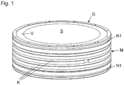
- the Figure 1 shows a stator S of a synchronous motor, which is arranged in a housing G.
- the coils of the stator S point towards the center of the stator S and are encased by a casting compound V.
- a rotor In the interior of the stator S, a rotor, not shown here, is arranged, on the outer circumference of which magnets are attached. By suitably energizing the coils, the rotor can be set in a rotary motion or a torque can be applied.
- cooling channels K are arranged, which are limited to a central area.
- circumferential grooves N1 for receiving sealing rings are made.
- the two outer regions of the lateral surface M which also have the circumferential grooves N1 are machined particularly precisely.
- these areas should prevent the escape of coolant either by means of a separate cover or by means of a corresponding application-side receptacle; on the other hand, these particularly precisely machined sub-areas also serve as a mechanical reference for installing the drive.
- the Figure 2 shows an annular or cylindrical casing or cover A, which for example by means of a shrinking process on the in the Figure 1 Housing G according to the invention shown is applied.
- the cover A has a flat, non-curved area B1 on its outside, which can be milled to produce the cover A after a turning process.
- Two openings O each lie above one of the cooling channels K, so that cooling medium (for example 30% glycol in water) can be supplied or removed through these openings O.
- the cover A made of steel should have a thickness of approx. 5 mm - 8 mm, on the one hand to be stable enough and on the other hand not to bring in too much additional weight and also not to use up unnecessary additional installation space.
- the cover A also has threaded holes for attaching a connector.
- connection piece C is intended to be placed on the flat area B1 of the cover A and screwed to it.
- the connection piece C has two radial threaded openings C1 and two axial threaded openings C2.
- One of the two pairs can be connected with connection hoses for the cooling medium, the other, not required, pair can be closed.
- the threaded openings C1, C2 are connected to further openings C3 in the connection piece C, which correspond to the openings O of the cover A.
- the further openings C3 are each surrounded by a groove N2 into which sealing rings can be inserted.
- connection pieces C can also be used which have only a pair of threaded openings C1 or C2.
- the variant with axial and radial threaded openings C1, C2 can be used more flexibly.
- the Figure 4 shows the housing G with the cover A and the connection piece C in the assembled state.
- the connection piece C is screwed onto the flat area B1 of the cover A.
- the axial length of the cover A i.e. in the X direction
- Subregions R of the lateral surface M of the housing G are therefore not covered by the cover A and are therefore accessible for the assembly of the drive. In the axial direction X, these subregions R should be at least 2 mm wide.
- FIGS. 5 and 6 each show a section through the stator S, the housing G according to the invention and its cover A with connector C, which is necessary for closed cooling.
- one of the radial threaded openings C1 and one of the axial threaded openings C2 are connected to one of the further openings C3, these further openings C3 of the connection piece C corresponding to the openings O of the cover A and cooling channels K lying thereunder.
- the openings O are offset from one another both in the axial direction X and in the tangential direction Y.
- the axial offset is obtained by comparing the Figures 5 and 6 easy to see, the tangential offset is shown in the Figure 2 very clearly.
- the partial areas R are not covered by the cover A, so that these particularly precisely machined partial areas R are accessible for the assembly of the motor in an application.
- the sub-areas R with particularly precise machining each extend to below the cover A and each also include the grooves N1 into which the sealing rings D1 are inserted .
- the web between these channels K is also better cooled by the cooling medium that flows from one cooling channel K over the separating web into the next cooling channel K.
- a gap of approximately 0.1 mm to 0.2 mm is therefore even provided between the webs and the cover A.
- This path of the cooling medium also contributes to the pressure drop between the inlet and outlet of the cooling medium. Depending on the size of the motor, this pressure drop is between 1 bar and 5 bar.
- connection piece C The other openings C3 of the connection piece C are also sealed with sealing rings D2, which are inserted into the grooves N2. They can be easily exchanged after removing the connector C.
- connection piece C does not have a flat or planar area B1, so it is easier to manufacture. Instead, the connection piece C has a curved region B2 on its side facing the cover A, the curvature of which corresponds to the curvature of the cover A. While the connection piece C according to the first embodiment is suitable for any diameter of the housing G, the connection piece C according to this second embodiment has to be manufactured to match the diameter of the housing G in each case. In this second embodiment, too, the subregions R remain accessible for assembly of the motor. Radially protruding screws S1 are welded to the cover A, onto which the connection piece C is slipped and with which the connection piece C is fastened to the cover A. The other openings C3 are now not surrounded by a groove, but only provided with recesses into which suitable O-rings can be inserted.
- connection piece C can also have threaded openings for the tangential supply of coolant, in addition to the radial and axial ones Threaded openings C1, C2, or as a replacement for one of these two, or as the only feed.
Description
- Gekühltes Gehäuse für den Stator eines Direktantriebs
- Die vorliegende Erfindung betrifft ein gekühltes Gehäuse für den Stator eines Direktantriebs. Solche Direktantriebe sind dafür gedacht, ein hohes Drehmoment auch bei niedrigen Drehzahlen oder sogar im Stillstand zu erzeugen. Eine Kühlung durch einen auf der Welle des Antriebs montierten Ventilator kommt daher nicht in Betracht. Solche Direktantriebe werden stattdessen häufig über Kühlkanäle im Bereich des Stators gekühlt.
- Direktantriebe, und insbesondere Synchronmotoren, die ohne ein zwischengeschaltetes Getriebe ihr Drehmoment an eine Applikation abgeben, sind beispielsweise in der
US 5642013 beschrieben. Einen rotatorischen Motor zeigt die Figur 15. Ein mit Magneten besetzter Rotor (Sekundärteil) dreht sich innerhalb eines mit Spulen besetzten Stators (Primärteil). Durch geeignete Anordnung der Spulen und Magnete können die dabei auftretenden Rastkräfte klein gehalten werden. Um hohe Drehmomente zu erzeugen, fließen in den Spulen selektiv hohe Ströme, die bei niedrigen Drehzahlen oder gar im Stillstand lokal zu einem großen Wärmeeintrag führen. Eine Kühlung solcher Motoren ist daher wichtig. - Die
EP 2680408 B1 offenbart hierzu ein Gehäuse für einen solchen Synchronmotor, auf dessen äußerer Mantelfläche Kühlkanäle verlaufen, die von einem dünnen Blech auf der Mantelfläche des Gehäuses verschlossen sind. Eine axiale Zuführung eines Kühlmediums ist unmittelbar im Gehäuse vorgesehen. Das Blech ist mit dem Gehäuse verschweißt, um die Kühlkanäle abzudichten. Das Gehäuse dieses Motors muss also für die spezielle Variante der Kühlung vorbereitet sein. Man bezeichnet diese Variante auch als geschlossene Kühlung, da der Kühlkreislauf schon vor dem Einbau des Motors in eine Anwendung geschlossen und abgedichtet ist. Eine Verwendung dieses Motors in einer ebenfalls üblichen Variante, gemäß der die Abdichtung der umlaufenden Kühlkanäle erst durch die Montage in einer vom Anwender des Motors zur Verfügung gestellten Aufnahme für den Motor erfolgt, ist mit diesem Motor nicht möglich. Diese Variante wird auch als offene Kühlung bezeichnet, und wird manchmal bevorzugt, da die schon zum Zwecke der Abdichtung zumindest in Teilbereichen sehr genau bearbeitete Mantelfläche des Gehäuses auch zur genauen Ausrichtung des Antriebs dienen kann. In der geschlossenen Variante der Kühlung ist dieser genau bearbeitete Teilbereich nicht zugänglich. - Die
US 2011/0227446 A1 offenbart einen ganz ähnlichen Motor, bei dem eine radiale Zuführung des Kühlmittels durch Öffnungen in der Abdeckung vorgesehen ist. Die Befestigung dieses Motors erfolgt über stirnseitig am Gehäuse befestigte Lagerschilde. - Bisher mussten daher verschiedene Gehäusevarianten für solche Direktantriebe bereitgestellt werden, um die Antriebe sowohl für die geschlossene als auch für die offene Variante der Kühlung anbieten zu können.
- Es ist daher Aufgabe der Erfindung, ein gekühltes Gehäuse für den Stator eines Direktantriebs anzugeben, bei dem das Gehäuse sowohl für eine geschlossene als auch für eine offene Kühlung geeignet ist, und bei dem auch im Falle der geschlossenen Kühlung als Lagereferenz dienende Teilbereiche der Mantelfläche des Gehäuses zugänglich bleiben.
- Diese Aufgabe wird gelöst durch ein gekühltes Gehäuse gemäß Anspruch 1. Vorteilhafte Details des gekühlten Gehäuses ergeben sich auch aus den von Anspruch 1 abhängigen Ansprüchen.
- Es wird ein gekühltes Gehäuse für den Stator eines Direktantriebs offenbart, bei dem auf einer äußeren Mantelfläche des Gehäuses Kühlkanäle verlaufen, die durch eine auf der Mantelfläche angeordnete, ringförmige Abdeckung abgedichtet sind. Die Abdeckung weist Öffnungen als Einlass und Auslass für ein Kühlmedium auf. Die Abdeckung ist so außerdem angeordnet, dass Teilbereiche der Mantelfläche des Gehäuses frei bleiben.
- Die Abdeckung ist in axialer Richtung kürzer als das Gehäuse und mittig auf dem Gehäuse angeordnet, so dass an beiden Enden des Gehäuses Teilbereiche der Mantelfläche des Gehäuses zugänglich bleiben, die bei der Montage des Motors in einer Applikation als Referenz dienen können. Damit ist es möglich, das Gehäuse bzw. den ganzen Motor sowohl in einer Variante mit geschlossener Kühlung als auch in einer Variante mit offener Kühlung anzubieten, ohne hierfür verschiedene Gehäusevarianten vorhalten zu müssen. Für die geschlossene Variante wird die Abdeckung mit einem Schrumpfprozess am Gehäuse befestigt, wobei O-Ringe im Bereich der Kanten der Abdeckung für eine Abdichtung sorgen. Ohne separate Abdeckung kann der Motor auch in eine entsprechende Aufnahme einer Kundenapplikation eingebaut werden, wobei diese Aufnahme dann die Funktion der Abdeckung übernimmt.
- Es ist außerdem ein Anschlussstück vorgesehen, das an die Abdeckung geschraubt werden kann, mit dem wahlweise eine radiale, axiale oder auch tangentiale Zuführung des Kühlmediums erfolgen kann.
- Die besondere Ausgestaltung des Gehäuses ermöglicht es, ausgehend von einem Gehäuse für die offene Variante der Kühlung einen Antrieb mit geschlossener Kühlung aufzubauen, ohne dafür ein modifiziertes Gehäuse zu benötigen. Die Vorteile der offenen Kühlung bleiben dabei erhalten. Es ist damit möglich, einen auf Vorrat gefertigten Stator sowohl für die offene Variante der Kühlung zu verwenden, als auch für die geschlossene Variante. Für letztere wird innerhalb von Minuten eine Abdeckung aufgeschrumpft und auf Dichtigkeit geprüft. Diese Flexibilität reduziert den Aufwand in der Fertigung und bei der Lagerhaltung erheblich.
- Weitere Vorteile und Einzelheiten der vorliegenden Erfindung ergeben sich aus der nachfolgenden Beschreibung verschiedener Ausführungsformen anhand der Figuren.
- Dabei zeigt
- Figur 1
- den Stator eines Direktantriebs mit seinem erfindungsgemäßen Gehäuse,
- Figur 2
- eine Abdeckung für das erfindungsgemäße Gehäuse gemäß einem ersten Ausführungsbeispiel,
- Figur 3
- ein dazu passendes Anschlussstück in verschiedenen Ansichten,
- Figur 4
- den Stator mit geschlossener Kühlung gemäß erstem Ausführungsbeispiel im montierten Zustand,
- Figur 5 und 6
- Schnittansichten des montierten Stators mit dem erfindungsgemäßen Gehäuse,
- Figur 7
- eine Abdeckung für das erfindungsgemäße Gehäuse gemäß einem zweiten Ausführungsbeispiel,
- Figur 8
- ein dazu passendes Anschlussstück in verschiedenen Ansichten,
- Figur 9
- den Stator mit geschlossener Kühlung gemäß zweitem Ausführungsbeispiel im montierten Zustand.
- Die
Figur 1 zeigt einen Stator S eines Synchronmotors, der in einem Gehäuse G angeordnet ist. Die Spulen des Stators S weisen zum Zentrum des Stators S und sind von einer Vergussmasse V umhüllt. Im Inneren des Stators S ist ein hier nicht dargestellter Rotor angeordnet, auf dessen äußerem Umfang Magnete befestigt sind. Durch eine geeignete Bestromung der Spulen kann der Rotor in eine Drehbewegung versetzt werden, bzw. ein Drehmoment aufbringen. Auf der äußeren Mantelfläche M des Gehäuses G sind Kühlkanäle K angeordnet, die sich auf einen mittleren Bereich beschränken. In einem äußeren Bereich der Mantelfläche M, nahe der beiden Stirnseiten des Gehäuses G, sind umlaufende Nuten N1 zur Aufnahme von Dichtringen eingebracht. - Erfindungsgemäß sind die beiden äußeren Bereiche der Mantelfläche M, die auch die umlaufenden Nuten N1 aufweisen, besonders genau bearbeitet. Einerseits sollen diese Bereiche entweder mittels einer separaten Abdeckung oder durch eine entsprechende applikationsseitige Aufnahme den Austritt von Kühlmittel verhindern, andererseits dienen diese besonders genau bearbeiteten Teilbereiche auch als mechanische Referenz für den Einbau des Antriebs.
- Das in der
Figur 1 gezeigte erfindungsgemäße Gehäuse G kann nun sowohl für die geschlossene als auch für die offene Variante der Kühlung verwendet werden. Die für die geschlossene Variante der Kühlung notwendigen weiteren Merkmale werden in den folgenden Figuren beschrieben. - In den
Figuren 2 - 4 ist ein erstes Ausführungsbeispiel dargestellt. DieFigur 2 zeigt eine ringförmige oder zylindrische Ummantelung oder Abdeckung A, die beispielsweise mittels eines Schrumpfprozesses auf das in derFigur 1 dargestellte erfindungsgemäße Gehäuse G aufgebracht wird. Die Abdeckung A weist auf ihrer Außenseite einen flachen, nicht gekrümmten Bereich B1 auf, der nach einem Drehprozess zur Herstellung der Abdeckung A gefräst werden kann. Zwei Öffnungen O liegen jeweils über einem der Kühlkanäle K, so dass durch diese Öffnungen O Kühlmedium (z.B. 30% Glykol in Wasser) zugeführt bzw. abgeführt werden kann. Die aus Stahl gefertigte Abdeckung A sollte eine Dicke von ca. 5 mm - 8 mm aufweisen, um einerseits stabil genug zu sein und andererseits nicht zu viel zusätzliches Gewicht einzubringen und auch nicht unnötigen zusätzlichen Bauraum zu verbrauchen. Die Abdeckung A weist außerdem Gewindebohrungen zur Befestigung eines Anschlussstückes auf. - Die
Figur 3 zeigt so ein Anschlussstück C in zwei verschiedenen Ansichten. Dieses Anschlussstück C ist dazu vorgesehen, auf den flachen Bereich B1 der Abdeckung A aufgesetzt und mit diesem verschraubt zu werden. Das Anschlussstück C weist zwei radiale Gewindeöffnungen C1 und zwei axiale Gewindeöffnungen C2 auf. Eines der beiden Paare kann mit Anschlussschläuchen für Kühlmedium verbunden werden, das andere, nicht benötigte Paar kann verschlossen werden. Die Gewindeöffnungen C1, C2 sind mit weiteren Öffnungen C3 im Anschlussstück C verbunden, die mit den Öffnungen O der Abdeckung A korrespondieren. Die weiteren Öffnungen C3 sind jeweils mit einer Nut N2 umgeben, in die Dichtringe eingelegt werden können. Selbstverständlich können auch Anschlussstücke C verwendet werden, die nur ein Paar von Gewindeöffnungen C1 oder C2 aufweisen. Die Variante mit axialen und radialen Gewindeöffnungen C1, C2 ist aber flexibler einsetzbar. - Die
Figur 4 zeigt das Gehäuse G mit der Abdeckung A und dem Anschlussstück C im montierten Zustand. Hierfür wird nach dem Aufschrumpfen der Abdeckung A auf das Gehäuse G das Anschlussstück C an den flachen Bereich B1 der Abdeckung A geschraubt. Man erkennt schon in dieserFigur 4 , dass die axiale Länge der Abdeckung A (also in Richtung X) kleiner ist als die entsprechende Länge des Gehäuses G. Teilbereiche R der Mantelfläche M des Gehäuses G sind daher nicht von der Abdeckung A bedeckt und damit für die Montage des Antriebs zugänglich. In axialer Richtung X sollten diese Teilbereiche R wenigstens 2 mm breit sein. - Die
Figuren 5 und 6 zeigen jeweils einen Schnitt durch den Stator S, das erfindungsgemäße Gehäuse G und dessen für eine geschlossene Kühlung notwendige Abdeckung A mit Anschlussstück C. - Zunächst ist dargestellt, dass jeweils eine der radialen Gewindeöffnungen C1 und eine der axialen Gewindeöffnungen C2 mit einer der weiteren Öffnungen C3 verbunden sind, wobei diese weiteren Öffnungen C3 des Anschlussstücks C mit den Öffnungen O der Abdeckung A und darunter liegenden Kühlkanälen K korrespondieren. Um diese Anordnung zu ermöglichen ist es vorteilhaft, wenn die Öffnungen O sowohl in axialer Richtung X als auch in tangentialer Richtung Y gegeneinander versetzt sind. Der axiale Versatz ist durch Vergleich der
Figuren 5 und 6 gut zu erkennen, der tangentiale Versatz wird in derFigur 2 sehr deutlich. - Auch in den
Figuren 5 und 6 ist gut zu erkennen, dass die Teilbereiche R nicht von der Abdeckung A abgedeckt sind, so dass diese besonders genau bearbeiteten Teilbereiche R für die Montage des Motors in einer Applikation zugänglich sind. Die Teilbereiche R mit besonders genauer Bearbeitung (z.B. mit einem Mittenrauwert von Ra = 1,6 µm und einer hohen Anforderung an Maßhaltigkeit) erstrecken sich dabei jeweils bis unterhalb der Abdeckung A und umfassen jeweils auch noch die Nuten N1, in die Dichtringe D1 eingelegt sind. Im mittleren Bereich des Gehäuses G ist die Bearbeitung weniger genau (z.B. mit einem Mittenrauwert von Ra = 3,2 µm und einer reduzierten Anforderung an Maßhaltigkeit), denn eine Abdichtung der Kühlkanäle K durch die Abdeckung A untereinander ist weder notwendig noch erwünscht. Durch das Kühlmedium, das von einem Kühlkanal K über den trennenden Steg hinweg in den nächsten Kühlkanal K fließt, wird auch der Steg zwischen diesen Kanälen K besser gekühlt. Zwischen den Stegen und der Abdeckung A wird daher sogar ein Spalt von ca. 0,1 mm bis 0,2 mm vorgesehen. Auch dieser Weg des Kühlmediums trägt zum Druckabfall zwischen Einlass und Auslass des Kühlmediums bei. Dieser Druckabfall liegt ja nach Größe des Motors zwischen 1 bar und 5 bar. - Die weiteren Öffnungen C3 des Anschlussstücks C sind noch mit Dichtringen D2 abgedichtet, die in die Nuten N2 eingelegt sind. Sie lassen sich nach dem Abbau des Anschlussstückes C leicht auswechseln.
- Die
Figuren 7 - 9 beschreiben eine weitere Ausführungsform der Erfindung, die zu einer Kostenersparnis im Vergleich zur ersten Ausführungsform führen soll. Es sei hier nur auf die wesentlichen Unterschiede zu der in denFiguren 2 - 4 dargestellten ersten Ausführungsform eingegangen. - Die Abdeckung A weist keinen flachen oder ebenen Bereich B1 auf, sie ist daher einfacher herzustellen. Stattdessen weist das Anschlussstück C auf seiner der Abdeckung A zugewandten Seite einen gekrümmten Bereich B2 auf, dessen Krümmung mit der Krümmung der Abdeckung A korrespondiert. Während das Anschlussstück C gemäß der ersten Ausführungsform für jeden Durchmesser des Gehäuses G geeignet ist, muss das Anschlussstück C gemäß dieser zweiten Ausführungsform jeweils passend zum Durchmesser des Gehäuses G gefertigt werden. Auch in dieser zweiten Ausführungsform bleiben die Teilbereiche R für eine Montage des Motors zugänglich. An der Abdeckung A sind radial abstehende Schrauben S1 angeschweißt, auf die das Anschlussstück C aufgesteckt und mit denen das Anschlussstück C an der Abdeckung A befestigt wird. Die weiteren Öffnungen C3 sind nun nicht von einer Nut umgeben, sondern lediglich mit Vertiefungen versehen, in die passende O-Ringe eingelegt werden können.
- In einer Abwandlung der beiden vorgestellten Ausführungsbeispiele kann das Anschlussstück C auch Gewindeöffnungen zur tangentialen Zuführung von Kühlmittel aufweisen, und zwar zusätzlich zu den radialen und axialen Gewindeöffnungen C1, C2, oder auch als Ersatz für eine dieser beiden, oder als einzige Zuführung.
Claims (9)
- Gekühltes Gehäuse (G) für den Stator (S) eines Direktantriebs, bei dem auf einer äußeren Mantelfläche (M) des Gehäuses (G) Kühlkanäle (K) verlaufen, die durch eine auf der Mantelfläche (M) angeordnete, ringförmige Abdeckung (A) abgedichtet sind, wobei die Abdeckung (A) Öffnungen (O) als Einlass und Auslass für ein Kühlmedium aufweist, dadurch gekennzeichnet, dass die Abdeckung (A) so angeordnet ist, dass Teilbereiche (R) der Mantelfläche (M) des Gehäuses (G) nicht von der Abdeckung (A) abgedeckt sind, und dass die Abdeckung (A) in axialer Richtung (X) kürzer ist als die Mantelfläche (M) des Gehäuses (G), und dass die Teilbereiche (R) zwei stirnseitig an der Mantelfläche (M) umlaufende, ringförmige Bereiche sind, die bezüglich des Mittenrauwerts (Ra) und der Maßhaltigkeit mit einer höheren Genauigkeit bearbeitet sind als ein mit den Kühlkanälen (K) ausgestatteter mittlerer Bereich der Mantelfläche (M) zwischen den Teilbereichen (R), und dass die Teilbereiche (R) durch ihre Zugänglichkeit bei der Montage des Direktantriebs eine Lagereferenz für die Montage des Stators (S) und somit auch eine mechanische Referenz für einen Einbau des Direktantriebs bilden.
- Gekühltes Gehäuse nach Anspruch 1, dadurch gekennzeichnet, dass die Teilbereiche (R) in axialer Richtung (X) mindestens 2 mm breit sind.
- Gekühltes Gehäuse nach einem der vorhergehenden Ansprüche, dadurch gekennzeichnet, dass stirnseitig und beidseits der Kühlkanäle (K) zwischen der Abdeckung (A) und dem Gehäuse (G) Dichtungen (D1) in Nuten (N1) des Gehäuses (G) angeordnet sind.
- Gekühltes Gehäuse nach einem der vorhergehenden Ansprüche, dadurch gekennzeichnet, dass die Abdeckung (A) auf das Gehäuse (G) aufgeschrumpft ist.
- Gekühltes Gehäuse nach einem der vorhergehenden Ansprüche, dadurch gekennzeichnet, dass die Öffnungen (O) bezüglich der Mantelfläche (M) in axialer Richtung (X) und in tangentialer Richtung (Y) gegeneinander versetzt sind.
- Gekühltes Gehäuse nach einem der vorhergehenden Ansprüche, dadurch gekennzeichnet, dass ein Anschlussstück (C) mit der Abdeckung (A) verbunden ist, und dass das Anschlussstück (C) axiale und/oder radiale und/oder tangentiale Gewindeöffnungen (C1, C2) für die Kühlmediumversorgung aufweist, die mit den Öffnungen (O) der Abdeckung (A) korrespondieren.
- Gekühltes Gehäuse nach Anspruch 6, dadurch gekennzeichnet, dass die Abdeckung (A) einen ebenen Bereich (B1) aufweist, der als Anlagefläche für das Anschlussstück (C) dient.
- Gekühltes Gehäuse nach Anspruch 6, dadurch gekennzeichnet, dass das Anschlussstück (C) einen gekrümmten Bereich (B2) aufweist, der als Anlagefläche für die Abdeckung (A) dient.
- Direktantrieb, dessen Stator (S) in einem Gehäuse (G) nach einem der vorhergehenden Ansprüche angeordnet ist.
Priority Applications (2)
| Application Number | Priority Date | Filing Date | Title |
|---|---|---|---|
| EP17199873.5A EP3480929B1 (de) | 2017-11-03 | 2017-11-03 | Gekühltes gehäuse für den stator eines direktantriebs |
| US16/177,806 US10931172B2 (en) | 2017-11-03 | 2018-11-01 | Cooled housing for the stator of a direct drive |
Applications Claiming Priority (1)
| Application Number | Priority Date | Filing Date | Title |
|---|---|---|---|
| EP17199873.5A EP3480929B1 (de) | 2017-11-03 | 2017-11-03 | Gekühltes gehäuse für den stator eines direktantriebs |
Publications (2)
| Publication Number | Publication Date |
|---|---|
| EP3480929A1 EP3480929A1 (de) | 2019-05-08 |
| EP3480929B1 true EP3480929B1 (de) | 2021-04-28 |
Family
ID=60244974
Family Applications (1)
| Application Number | Title | Priority Date | Filing Date |
|---|---|---|---|
| EP17199873.5A Active EP3480929B1 (de) | 2017-11-03 | 2017-11-03 | Gekühltes gehäuse für den stator eines direktantriebs |
Country Status (2)
| Country | Link |
|---|---|
| US (1) | US10931172B2 (de) |
| EP (1) | EP3480929B1 (de) |
Families Citing this family (7)
| Publication number | Priority date | Publication date | Assignee | Title |
|---|---|---|---|---|
| EP3480929B1 (de) * | 2017-11-03 | 2021-04-28 | Etel S.A. | Gekühltes gehäuse für den stator eines direktantriebs |
| NL2023483B1 (en) | 2019-07-11 | 2021-02-03 | Tecnotion Assets B V | Permanent Magnet Synchronous Torque Motor |
| EP3996255A1 (de) * | 2020-11-04 | 2022-05-11 | Etel S.A. | Statorkühlgehäuse für einen stator eines rotierenden elektromotors |
| EP4012896A1 (de) * | 2020-12-10 | 2022-06-15 | Etel S.A. | Statorkühlgehäuse für einen stator eines rotierenden elektromotors |
| EP4016807A1 (de) * | 2020-12-17 | 2022-06-22 | Rolls-Royce Deutschland Ltd & Co KG | Statorkühlmantelvorrichtung für einen elektromotor, verfahren zum zusammenbau eines statorkühlmantels und elektromotor mit einer statorkühlmantelvorrichtung |
| CN114567126B (zh) * | 2022-03-07 | 2023-04-07 | 杭州桢正玮顿运动控制技术有限公司 | 一种油冷式永磁同步电机 |
| DE202023103288U1 (de) | 2023-06-15 | 2023-07-03 | Hiwin Mikrosystem Corp. | Adapter und Kühlstruktur mit Adapter |
Family Cites Families (30)
| Publication number | Priority date | Publication date | Assignee | Title |
|---|---|---|---|---|
| US3601884A (en) * | 1968-05-20 | 1971-08-31 | Westinghouse Electric Corp | Method of constructing parts suitable for high heat flux removal in arc heaters |
| US4516044A (en) * | 1984-05-31 | 1985-05-07 | Cincinnati Milacron Inc. | Heat exchange apparatus for electric motor and electric motor equipped therewith |
| JPS6416238A (en) * | 1987-07-09 | 1989-01-19 | Fanuc Ltd | Method of cooling motor |
| FR2726948B1 (fr) | 1994-11-16 | 1996-12-20 | Wavre Nicolas | Moteur synchrone a aimants permanents |
| US7009317B2 (en) * | 2004-01-14 | 2006-03-07 | Caterpillar Inc. | Cooling system for an electric motor |
| US6909210B1 (en) * | 2004-02-06 | 2005-06-21 | Emerson Electric Co. | Cooling system for dynamoelectric machine |
| US7322103B2 (en) * | 2004-06-04 | 2008-01-29 | Deere & Company | Method of making a motor/generator cooling jacket |
| US20070075595A1 (en) * | 2005-09-30 | 2007-04-05 | Rajmohan Narayanan | Motor frame having embedded cooling coil |
| US7591147B2 (en) * | 2006-11-01 | 2009-09-22 | Honeywell International Inc. | Electric motor cooling jacket resistor |
| DE102005052364A1 (de) * | 2005-11-02 | 2007-05-03 | Siemens Ag | Elektromotor |
| TW200805861A (en) * | 2006-07-03 | 2008-01-16 | Joy Ride Technology Co Ltd | Airtight motor capable of dissipating heat |
| US7626292B2 (en) * | 2007-07-03 | 2009-12-01 | Caterpillar Inc. | Cast groove electric motor/generator cooling mechanism |
| US8183723B2 (en) * | 2007-07-03 | 2012-05-22 | Caterpillar Inc. | Cooling jacket and stator assembly for rotary electric device |
| FR2935560B1 (fr) * | 2008-09-03 | 2011-07-15 | Michelin Soc Tech | Stator pour machine electrique tournante et son procede de fabrication |
| US7965002B2 (en) * | 2008-10-07 | 2011-06-21 | Caterpillar Inc. | Helical conduit enabled for casting inside a housing |
| USD624015S1 (en) * | 2008-12-17 | 2010-09-21 | Baldor Electric Company | Liquid cooled motor |
| DE102009031727A1 (de) * | 2009-07-04 | 2010-02-04 | Daimler Ag | Gehäuseanordnung für eine flüssigkeitsgekühlte elektrische Maschine |
| DE102009051881A1 (de) * | 2009-11-04 | 2011-05-05 | Dr. Ing. H.C. F. Porsche Aktiengesellschaft | Kühlvorrichtung für eine Elektromaschinenanordnung |
| US8487489B2 (en) * | 2010-07-30 | 2013-07-16 | General Electric Company | Apparatus for cooling an electric machine |
| US8629587B2 (en) * | 2010-12-23 | 2014-01-14 | Asia Vital Components Co., Ltd. | Water-cooling structure for electric motor |
| JP5330495B2 (ja) * | 2011-12-27 | 2013-10-30 | 六逸科技股▲ふん▼有限公司 | モータ |
| JP2013141334A (ja) * | 2011-12-28 | 2013-07-18 | Denso Corp | 回転電機 |
| EP2680408B1 (de) | 2012-06-26 | 2014-12-17 | Etel S. A.. | Rahmen mit integrierter Kühlung für einen elektrischen Antrieb |
| US9209661B2 (en) * | 2012-10-02 | 2015-12-08 | Remy Technologies, L.L.C. | Electric machine including a housing having materially integrally formed coolant channels and an outer sleeve |
| KR101995846B1 (ko) * | 2012-12-17 | 2019-07-03 | 엘지이노텍 주식회사 | 냉각부재 일체 결합형 전동기 |
| US20140246933A1 (en) * | 2013-03-04 | 2014-09-04 | Remy Technologies, Llc | Liquid-cooled rotary electric machine having heat source-surrounding fluid passage |
| US9525325B2 (en) * | 2013-03-04 | 2016-12-20 | Remy Technologies, Llc | Liquid-cooled rotary electric machine having axial end cooling |
| DE102013213435A1 (de) * | 2013-07-09 | 2015-01-15 | Schaeffler Technologies Gmbh & Co. Kg | Kühlsystem für eine dynamoelektrische Maschine |
| EP3480929B1 (de) * | 2017-11-03 | 2021-04-28 | Etel S.A. | Gekühltes gehäuse für den stator eines direktantriebs |
| JP6914904B2 (ja) * | 2018-11-09 | 2021-08-04 | 本田技研工業株式会社 | 回転電機のステータユニット |
-
2017
- 2017-11-03 EP EP17199873.5A patent/EP3480929B1/de active Active
-
2018
- 2018-11-01 US US16/177,806 patent/US10931172B2/en active Active
Non-Patent Citations (1)
| Title |
|---|
| None * |
Also Published As
| Publication number | Publication date |
|---|---|
| US20190140519A1 (en) | 2019-05-09 |
| EP3480929A1 (de) | 2019-05-08 |
| US10931172B2 (en) | 2021-02-23 |
Similar Documents
| Publication | Publication Date | Title |
|---|---|---|
| EP3480929B1 (de) | Gekühltes gehäuse für den stator eines direktantriebs | |
| DE4331560B4 (de) | Magnetisch gekuppelte Kreiselpumpe | |
| EP2503104B1 (de) | Turbomaschine | |
| DE102005002897B4 (de) | Flüssigkeitsgekühlte elektrische Maschine mit Gussgehäuse | |
| DE19780317B4 (de) | Elektrische Maschine | |
| DE102011056007A1 (de) | Kühlsystem für eine rotierende elektrische Maschine höchster Leistungsdichte | |
| EP0915554A2 (de) | Elektromotor | |
| EP1173917A1 (de) | Stromerzeugereinheit aus generator und hubkolbenverbrennungsmotor als antrieb | |
| DE10258778A1 (de) | Elektrische Maschine mit Heatpipes | |
| EP1485980A1 (de) | Drehmomentmotor in segmentbauweise | |
| DE112014007129T5 (de) | Statorkern für eine elektrische Rotationsmaschine, elektrische Rotationsmaschine und Verfahren zur Herstellung einer elektrischen Rotationsmaschine | |
| DE102013211408B4 (de) | Kühleinrichtung zur Kühlung einer elektrischen Maschine und entsprechende elektrische Maschine mit Kühleinrichtung | |
| DE102009053102A1 (de) | Axiallageranordnung für eine Welle eines Turboladers | |
| DE102013018720A1 (de) | Kurbelwellen-Startergenerator und Gehäuse für einen Kurbelwellen-Startergenerator | |
| DE112016002202T5 (de) | Elektrische Rotationsmaschine | |
| EP1857681B1 (de) | Drehschiebervakuumpumpe mit Spaltrohrmotor | |
| WO2020126076A1 (de) | Elektromotor mit einem statorgehäuseteil | |
| WO2018197192A1 (de) | Elektrische maschine | |
| EP3297129A1 (de) | Rotor für eine elektrische rotierende maschine | |
| EP3391510B1 (de) | Befestigung eines polrades auf der welle einer elektrischen rotierenden maschine | |
| DE102019215693A1 (de) | Elektrische Maschine und Verfahren zur Herstellung der elektrischen Maschine | |
| DE102009053101A1 (de) | Aufnahmeeinrichtung für das Laufzeug eines Turboladers | |
| EP0988454A1 (de) | Dichtring eines schwenkmotors | |
| DE102016201691A1 (de) | Flüssigkeitsgekühlte elektrische Maschine für ein Kraftfahrzeug | |
| DE102018206401A1 (de) | Elektromotor und Verfahren zur Herstellung desselben |
Legal Events
| Date | Code | Title | Description |
|---|---|---|---|
| PUAI | Public reference made under article 153(3) epc to a published international application that has entered the european phase |
Free format text: ORIGINAL CODE: 0009012 |
|
| STAA | Information on the status of an ep patent application or granted ep patent |
Free format text: STATUS: THE APPLICATION HAS BEEN PUBLISHED |
|
| AK | Designated contracting states |
Kind code of ref document: A1 Designated state(s): AL AT BE BG CH CY CZ DE DK EE ES FI FR GB GR HR HU IE IS IT LI LT LU LV MC MK MT NL NO PL PT RO RS SE SI SK SM TR |
|
| AX | Request for extension of the european patent |
Extension state: BA ME |
|
| STAA | Information on the status of an ep patent application or granted ep patent |
Free format text: STATUS: REQUEST FOR EXAMINATION WAS MADE |
|
| 17P | Request for examination filed |
Effective date: 20191108 |
|
| RBV | Designated contracting states (corrected) |
Designated state(s): AL AT BE BG CH CY CZ DE DK EE ES FI FR GB GR HR HU IE IS IT LI LT LU LV MC MK MT NL NO PL PT RO RS SE SI SK SM TR |
|
| STAA | Information on the status of an ep patent application or granted ep patent |
Free format text: STATUS: EXAMINATION IS IN PROGRESS |
|
| 17Q | First examination report despatched |
Effective date: 20200420 |
|
| GRAP | Despatch of communication of intention to grant a patent |
Free format text: ORIGINAL CODE: EPIDOSNIGR1 |
|
| STAA | Information on the status of an ep patent application or granted ep patent |
Free format text: STATUS: GRANT OF PATENT IS INTENDED |
|
| INTG | Intention to grant announced |
Effective date: 20201125 |
|
| GRAS | Grant fee paid |
Free format text: ORIGINAL CODE: EPIDOSNIGR3 |
|
| GRAA | (expected) grant |
Free format text: ORIGINAL CODE: 0009210 |
|
| STAA | Information on the status of an ep patent application or granted ep patent |
Free format text: STATUS: THE PATENT HAS BEEN GRANTED |
|
| AK | Designated contracting states |
Kind code of ref document: B1 Designated state(s): AL AT BE BG CH CY CZ DE DK EE ES FI FR GB GR HR HU IE IS IT LI LT LU LV MC MK MT NL NO PL PT RO RS SE SI SK SM TR |
|
| REG | Reference to a national code |
Ref country code: GB Ref legal event code: FG4D Free format text: NOT ENGLISH |
|
| REG | Reference to a national code |
Ref country code: CH Ref legal event code: EP Ref country code: CH Ref legal event code: NV Representative=s name: ICB INGENIEURS CONSEILS EN BREVETS SA, CH |
|
| REG | Reference to a national code |
Ref country code: AT Ref legal event code: REF Ref document number: 1388258 Country of ref document: AT Kind code of ref document: T Effective date: 20210515 |
|
| REG | Reference to a national code |
Ref country code: DE Ref legal event code: R096 Ref document number: 502017010188 Country of ref document: DE |
|
| REG | Reference to a national code |
Ref country code: IE Ref legal event code: FG4D Free format text: LANGUAGE OF EP DOCUMENT: GERMAN |
|
| REG | Reference to a national code |
Ref country code: NL Ref legal event code: FP |
|
| REG | Reference to a national code |
Ref country code: LT Ref legal event code: MG9D |
|
| PG25 | Lapsed in a contracting state [announced via postgrant information from national office to epo] |
Ref country code: BG Free format text: LAPSE BECAUSE OF FAILURE TO SUBMIT A TRANSLATION OF THE DESCRIPTION OR TO PAY THE FEE WITHIN THE PRESCRIBED TIME-LIMIT Effective date: 20210728 Ref country code: HR Free format text: LAPSE BECAUSE OF FAILURE TO SUBMIT A TRANSLATION OF THE DESCRIPTION OR TO PAY THE FEE WITHIN THE PRESCRIBED TIME-LIMIT Effective date: 20210428 Ref country code: LT Free format text: LAPSE BECAUSE OF FAILURE TO SUBMIT A TRANSLATION OF THE DESCRIPTION OR TO PAY THE FEE WITHIN THE PRESCRIBED TIME-LIMIT Effective date: 20210428 Ref country code: FI Free format text: LAPSE BECAUSE OF FAILURE TO SUBMIT A TRANSLATION OF THE DESCRIPTION OR TO PAY THE FEE WITHIN THE PRESCRIBED TIME-LIMIT Effective date: 20210428 |
|
| PG25 | Lapsed in a contracting state [announced via postgrant information from national office to epo] |
Ref country code: IS Free format text: LAPSE BECAUSE OF FAILURE TO SUBMIT A TRANSLATION OF THE DESCRIPTION OR TO PAY THE FEE WITHIN THE PRESCRIBED TIME-LIMIT Effective date: 20210828 Ref country code: LV Free format text: LAPSE BECAUSE OF FAILURE TO SUBMIT A TRANSLATION OF THE DESCRIPTION OR TO PAY THE FEE WITHIN THE PRESCRIBED TIME-LIMIT Effective date: 20210428 Ref country code: GR Free format text: LAPSE BECAUSE OF FAILURE TO SUBMIT A TRANSLATION OF THE DESCRIPTION OR TO PAY THE FEE WITHIN THE PRESCRIBED TIME-LIMIT Effective date: 20210729 Ref country code: NO Free format text: LAPSE BECAUSE OF FAILURE TO SUBMIT A TRANSLATION OF THE DESCRIPTION OR TO PAY THE FEE WITHIN THE PRESCRIBED TIME-LIMIT Effective date: 20210728 Ref country code: PL Free format text: LAPSE BECAUSE OF FAILURE TO SUBMIT A TRANSLATION OF THE DESCRIPTION OR TO PAY THE FEE WITHIN THE PRESCRIBED TIME-LIMIT Effective date: 20210428 Ref country code: PT Free format text: LAPSE BECAUSE OF FAILURE TO SUBMIT A TRANSLATION OF THE DESCRIPTION OR TO PAY THE FEE WITHIN THE PRESCRIBED TIME-LIMIT Effective date: 20210830 Ref country code: SE Free format text: LAPSE BECAUSE OF FAILURE TO SUBMIT A TRANSLATION OF THE DESCRIPTION OR TO PAY THE FEE WITHIN THE PRESCRIBED TIME-LIMIT Effective date: 20210428 Ref country code: RS Free format text: LAPSE BECAUSE OF FAILURE TO SUBMIT A TRANSLATION OF THE DESCRIPTION OR TO PAY THE FEE WITHIN THE PRESCRIBED TIME-LIMIT Effective date: 20210428 |
|
| PG25 | Lapsed in a contracting state [announced via postgrant information from national office to epo] |
Ref country code: SK Free format text: LAPSE BECAUSE OF FAILURE TO SUBMIT A TRANSLATION OF THE DESCRIPTION OR TO PAY THE FEE WITHIN THE PRESCRIBED TIME-LIMIT Effective date: 20210428 Ref country code: SM Free format text: LAPSE BECAUSE OF FAILURE TO SUBMIT A TRANSLATION OF THE DESCRIPTION OR TO PAY THE FEE WITHIN THE PRESCRIBED TIME-LIMIT Effective date: 20210428 Ref country code: EE Free format text: LAPSE BECAUSE OF FAILURE TO SUBMIT A TRANSLATION OF THE DESCRIPTION OR TO PAY THE FEE WITHIN THE PRESCRIBED TIME-LIMIT Effective date: 20210428 Ref country code: DK Free format text: LAPSE BECAUSE OF FAILURE TO SUBMIT A TRANSLATION OF THE DESCRIPTION OR TO PAY THE FEE WITHIN THE PRESCRIBED TIME-LIMIT Effective date: 20210428 Ref country code: CZ Free format text: LAPSE BECAUSE OF FAILURE TO SUBMIT A TRANSLATION OF THE DESCRIPTION OR TO PAY THE FEE WITHIN THE PRESCRIBED TIME-LIMIT Effective date: 20210428 Ref country code: RO Free format text: LAPSE BECAUSE OF FAILURE TO SUBMIT A TRANSLATION OF THE DESCRIPTION OR TO PAY THE FEE WITHIN THE PRESCRIBED TIME-LIMIT Effective date: 20210428 Ref country code: ES Free format text: LAPSE BECAUSE OF FAILURE TO SUBMIT A TRANSLATION OF THE DESCRIPTION OR TO PAY THE FEE WITHIN THE PRESCRIBED TIME-LIMIT Effective date: 20210428 |
|
| REG | Reference to a national code |
Ref country code: DE Ref legal event code: R097 Ref document number: 502017010188 Country of ref document: DE |
|
| PLBE | No opposition filed within time limit |
Free format text: ORIGINAL CODE: 0009261 |
|
| STAA | Information on the status of an ep patent application or granted ep patent |
Free format text: STATUS: NO OPPOSITION FILED WITHIN TIME LIMIT |
|
| 26N | No opposition filed |
Effective date: 20220131 |
|
| PG25 | Lapsed in a contracting state [announced via postgrant information from national office to epo] |
Ref country code: IS Free format text: LAPSE BECAUSE OF FAILURE TO SUBMIT A TRANSLATION OF THE DESCRIPTION OR TO PAY THE FEE WITHIN THE PRESCRIBED TIME-LIMIT Effective date: 20210828 Ref country code: AL Free format text: LAPSE BECAUSE OF FAILURE TO SUBMIT A TRANSLATION OF THE DESCRIPTION OR TO PAY THE FEE WITHIN THE PRESCRIBED TIME-LIMIT Effective date: 20210428 |
|
| PG25 | Lapsed in a contracting state [announced via postgrant information from national office to epo] |
Ref country code: MC Free format text: LAPSE BECAUSE OF FAILURE TO SUBMIT A TRANSLATION OF THE DESCRIPTION OR TO PAY THE FEE WITHIN THE PRESCRIBED TIME-LIMIT Effective date: 20210428 |
|
| GBPC | Gb: european patent ceased through non-payment of renewal fee |
Effective date: 20211103 |
|
| PG25 | Lapsed in a contracting state [announced via postgrant information from national office to epo] |
Ref country code: LU Free format text: LAPSE BECAUSE OF NON-PAYMENT OF DUE FEES Effective date: 20211103 Ref country code: BE Free format text: LAPSE BECAUSE OF NON-PAYMENT OF DUE FEES Effective date: 20211130 |
|
| REG | Reference to a national code |
Ref country code: BE Ref legal event code: MM Effective date: 20211130 |
|
| PG25 | Lapsed in a contracting state [announced via postgrant information from national office to epo] |
Ref country code: IE Free format text: LAPSE BECAUSE OF NON-PAYMENT OF DUE FEES Effective date: 20211103 Ref country code: GB Free format text: LAPSE BECAUSE OF NON-PAYMENT OF DUE FEES Effective date: 20211103 |
|
| PG25 | Lapsed in a contracting state [announced via postgrant information from national office to epo] |
Ref country code: CY Free format text: LAPSE BECAUSE OF FAILURE TO SUBMIT A TRANSLATION OF THE DESCRIPTION OR TO PAY THE FEE WITHIN THE PRESCRIBED TIME-LIMIT Effective date: 20210428 |
|
| PG25 | Lapsed in a contracting state [announced via postgrant information from national office to epo] |
Ref country code: HU Free format text: LAPSE BECAUSE OF FAILURE TO SUBMIT A TRANSLATION OF THE DESCRIPTION OR TO PAY THE FEE WITHIN THE PRESCRIBED TIME-LIMIT; INVALID AB INITIO Effective date: 20171103 |
|
| PGFP | Annual fee paid to national office [announced via postgrant information from national office to epo] |
Ref country code: NL Payment date: 20231120 Year of fee payment: 7 |
|
| PGFP | Annual fee paid to national office [announced via postgrant information from national office to epo] |
Ref country code: IT Payment date: 20231124 Year of fee payment: 7 Ref country code: FR Payment date: 20231120 Year of fee payment: 7 Ref country code: DE Payment date: 20231121 Year of fee payment: 7 Ref country code: CH Payment date: 20231201 Year of fee payment: 7 Ref country code: AT Payment date: 20231121 Year of fee payment: 7 |