EP3480923A1 - Method for producing corona discharge-preventing structure, corona discharge-preventing structure, and rotating electrical machine - Google Patents
Method for producing corona discharge-preventing structure, corona discharge-preventing structure, and rotating electrical machine Download PDFInfo
- Publication number
- EP3480923A1 EP3480923A1 EP16907209.7A EP16907209A EP3480923A1 EP 3480923 A1 EP3480923 A1 EP 3480923A1 EP 16907209 A EP16907209 A EP 16907209A EP 3480923 A1 EP3480923 A1 EP 3480923A1
- Authority
- EP
- European Patent Office
- Prior art keywords
- corona discharge
- producing
- electrically conductive
- tape
- fiber
- Prior art date
- Legal status (The legal status is an assumption and is not a legal conclusion. Google has not performed a legal analysis and makes no representation as to the accuracy of the status listed.)
- Granted
Links
Images


Classifications
-
- H—ELECTRICITY
- H02—GENERATION; CONVERSION OR DISTRIBUTION OF ELECTRIC POWER
- H02K—DYNAMO-ELECTRIC MACHINES
- H02K3/00—Details of windings
- H02K3/32—Windings characterised by the shape, form or construction of the insulation
- H02K3/40—Windings characterised by the shape, form or construction of the insulation for high voltage, e.g. affording protection against corona discharges
-
- H—ELECTRICITY
- H01—ELECTRIC ELEMENTS
- H01B—CABLES; CONDUCTORS; INSULATORS; SELECTION OF MATERIALS FOR THEIR CONDUCTIVE, INSULATING OR DIELECTRIC PROPERTIES
- H01B13/00—Apparatus or processes specially adapted for manufacturing conductors or cables
-
- H—ELECTRICITY
- H01—ELECTRIC ELEMENTS
- H01B—CABLES; CONDUCTORS; INSULATORS; SELECTION OF MATERIALS FOR THEIR CONDUCTIVE, INSULATING OR DIELECTRIC PROPERTIES
- H01B13/00—Apparatus or processes specially adapted for manufacturing conductors or cables
- H01B13/004—Apparatus or processes specially adapted for manufacturing conductors or cables for manufacturing rigid-tube cables
-
- H—ELECTRICITY
- H02—GENERATION; CONVERSION OR DISTRIBUTION OF ELECTRIC POWER
- H02K—DYNAMO-ELECTRIC MACHINES
- H02K15/00—Processes or apparatus specially adapted for manufacturing, assembling, maintaining or repairing of dynamo-electric machines
- H02K15/10—Applying solid insulation to windings, stators or rotors, e.g. applying insulating tapes
-
- H—ELECTRICITY
- H02—GENERATION; CONVERSION OR DISTRIBUTION OF ELECTRIC POWER
- H02K—DYNAMO-ELECTRIC MACHINES
- H02K15/00—Processes or apparatus specially adapted for manufacturing, assembling, maintaining or repairing of dynamo-electric machines
- H02K15/10—Applying solid insulation to windings, stators or rotors, e.g. applying insulating tapes
- H02K15/105—Applying solid insulation to windings, stators or rotors, e.g. applying insulating tapes to the windings
-
- H—ELECTRICITY
- H02—GENERATION; CONVERSION OR DISTRIBUTION OF ELECTRIC POWER
- H02K—DYNAMO-ELECTRIC MACHINES
- H02K3/00—Details of windings
- H02K3/30—Windings characterised by the insulating material
-
- H—ELECTRICITY
- H02—GENERATION; CONVERSION OR DISTRIBUTION OF ELECTRIC POWER
- H02K—DYNAMO-ELECTRIC MACHINES
- H02K7/00—Arrangements for handling mechanical energy structurally associated with dynamo-electric machines, e.g. structural association with mechanical driving motors or auxiliary dynamo-electric machines
- H02K7/08—Structural association with bearings
- H02K7/083—Structural association with bearings radially supporting the rotary shaft at both ends of the rotor
Definitions
- the present invention relates to a method for producing a corona discharge-preventing structure, a corona discharge-preventing structure, and a rotating electrical machine.
- an electric tree is generated.
- the electric tree is believed to be generated by starting from a high electric field concentration parts such as an air gap or foreign matters between an electrode and an insulator, foreign matters, projections and voids in an insulator, and particularly in an air gap immediately under a corona discharge-preventing layer.
- the corona discharge-preventing layer is a part where semiconductor tapes are wound around the outermost layer to prevent corona discharge with making no air gap between overlapping layers of mica insulation tape, particularly in a case that insulation structures have high-voltage parts.
- inverters have been prevailing.
- the lifetime of an insulating material of a coil conductive wire may be significantly reduced when the motor is used in a state where an impulse voltage including inverter surge repeatedly acts. Therefore, for example, such situation occurs, in which insulation for normal rated voltage 6.6 kV is forced to be used for an inverter-driven motor for rated voltage 3.3 kV. In such cases, corona discharge-preventing tapes are compelled to be used.
- an electrical insulating structure for a conductor used in a rotating electrical machine a coil conductor is typically covered with an insulator having an insulating material.
- Such a conductor easily reaching high temperatures often has a mica electrical insulating structure using mica which is a kind of silicate minerals as an insulating material of high insulation class capable of withstanding comparatively high temperatures.
- IEC International Electrotechnical Commission
- Patent Document 1 U.S. Published Application No. 2015/0101845-A1
- the insulation lifetime of a formed-wound electrical motor for high voltage is significantly influenced by a main insulation and a turn insulation which are disposed inside a stator core. If such a problem occurs where the corona discharge-preventing layers are vanished, reliability of the electrical motor degrades remarkably. In such main insulations and turn insulations, the mica electrical insulating structure is often used.
- the mica electrical insulating structure as the main insulation is formed, in most cases, by impregnating a mica insulating tape with epoxy resin.
- the mica insulating tape is composed of mica and an epoxy glass layer.
- the mica insulating tape thus configured is wound around a coil conductor and then impregnated with the epoxy resin, whereby insulation treatment by the mica electrical insulating structure is performed.
- the corona discharge cannot be suppressed so much as expected, due to the influence of the moisture in the environmental air.
- An object of the invention is to enhance the anti-corona discharge property in an insulation structure.
- a method for producing a corona discharge-preventing structure for covering the outer surface of a to-be-insulated object comprising: a tape producing step of producing a corona discharge-preventing tape including a macromolecular polymer added with an electrically conductive powder and non-electrically conductive nanoparticles; a main insulating step of winding a main insulating tape around the to-be-insulated object; and a winding step of winding the corona discharge-preventing tape around the outer surface of the to-be-insulated object around which the main insulating tape has been wound.
- a corona discharge-preventing structure configured to prevent corona discharge in a to-be-insulated object, by covering the outer surface of the object, and comprising: a main insulating part provided on the outer surface of the to-be-insulated object; and a fiber-reinforced cloth shaped like tape and wound around the outer surface of the main insulating part; an electrically conductive powder dispersed in the fiber-reinforced cloth; and non-electrically conductive nanoparticles dispersed in the fiber-reinforced cloth.
- a rotating electrical machine comprising: a rotor having an axially extending rotor shaft and a rotor core disposed radially outside the rotor shaft; a stator having a hollow cylindrical stator core disposed outside the rotor core via a gap, and stator winding conductors laid in a plurality of slots, the slots formed in an inner surface of the stator core with circumferential intervals therebetween and extending to axially both ends of the stator core; two bearings rotatably supporting the rotor shaft at both axial sides sandwiching the rotor core therebetween; a frame housing the rotor core and the stator; a main insulating part provided on each of the stator winding conductors to electrically insulate the stator winding conductors; and a corona discharge-preventing structure provided outside the main insulating part, wherein the corona discharge-preventing structure has: fiber-reinforced cloth shaped like a tape and wound around the outer surface
- To-be-insulated objects or the objects to be insulated are not limited to the stator winding conductors. That is, it is applicable to any high voltage applied conductors as long as they have a structure where its outer surface is covered by the electrical insulating structure.
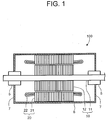
- FIG. 1 is a sectional longitudinal view illustrating the structure of a rotation electrical machine according to an embodiment.
- the rotation electrical machine 100 has a rotor 10, a stator 20, a frame 6 surrounding radially outside of the rotor 10 and the stator 20, and bearing brackets 7 attached to the axial ends of the frame 6.
- the rotor 10 has a rotor shaft 11 extending in its longitudinal direction and a rotor core 12 attached to radially outside the rotor shaft 11.
- the rotor shaft 11 is rotatably supported at both axial sides thereof by bearings 5.
- Each of the bearings 5 is stationarily supported by each of the bearing brackets 7.
- the stator 20 has a stator core 21 disposed radially outside the rotor core 12 so as to be spaced therefrom and stator windings 22 penetrating inside the stator core 21.
- a plurality of stator slots are formed along the inner surface of the stator core 21 with circumferential intervals therebetween and extend up to axially both ends of the stator core 21.
- Conductors 24 ( FIG. 2 ) for the stator winding 22 are disposed in each stator slot.
- FIG. 2 is a perspective view for explaining an electrical insulating structure and a tape-wound conductor according to the present embodiment.
- the plurality of stator winding conductors 24 constituting the stator windings 22 form a laminated conductor 23. Specifically, seven conductors 24 are arranged in one column, and two columns form the laminated conductor 23 by fourteen conductors 24 in total. The number of laminated layers and the number of columns mentioned here are merely illustrative, and any number of the conductors 24 may be arranged in one or three or more columns.
- Each stator winding conductor 24 is applied with a turn insulation 25 provided outside thereof. Accordingly, the outer surface of the laminated conductor 23 is covered by the turn insulation 25.
- a main insulation tape 40 serving as a main insulation is wound outside the laminated conductor 23 applied with the turn insulation 25 to form a main insulated part 49 outside the laminated conductor 23, whereby a tape-wound conductor 50 is obtained.
- corona discharge-preventing tapes 80 are wound around the outermost layer.
- the corona discharge-preventing tapes 80 are used to equalize the potential of the surface of each stator winding conductor 24 to the surface potential of the stator core 21, thereby to suppress the discharge between the stator winding conductors 24 and the stator core 21.
- the corona discharge-preventing tapes 80 are helically wound, with each turn contacting the immediately preceding turn as shown in FIG. 2 .
- the tape 80 may be wound, with each turn overlapping, in part, the immediately preceding turn.
- FIG. 3 is a flowchart showing a method for producing an insulation structure according to the present embodiment.
- a corona discharge-preventing tapes 80 are produced (Step S10).
- a main insulating tapes 40 are wound around a laminated conductor 23 as a to-be-insulated object (Step S20).
- taping is performed, with winding the corona discharge-preventing tapes 80 around the wound main insulating tapes 40 (Step S30).
- laminated conductors 23 wound with the corona discharge-preventing tape 80 are incorporated into the stator core 21, assembling a windings-incorporated object 90 ( FIG. 8 ), which will be described later (Step S40).
- the windings-incorporated object 90 so assembled is set in an impregnation apparatus 60.
- the windings-incorporated object 90 is impregnated with macromolecular polymer (Step S50).
- Step S10 of the method for producing the corona discharge-preventing tape 80 is described in detail below.
- an electrically conductive powder 82 and non-electrically conductive nanoparticles 83 are mixed with a macromolecular polymer 84 to prepare a mixture (Step S11).
- the macromolecular polymer 84 is, for example, unsaturated polyester or epoxy resin.
- FIG. 4 is a sectional elevational view illustrating the state in Step S11 of the method for producing the corona discharge-preventing tape.
- the electrically conductive powder 82 and the non-electrically conductive nanoparticles 83 are added to the macromolecular polymer 84 stored in a storage vessel 87. While the electrically conductive powder 82 and non-electrically conductive nanoparticles 83 are being added, the macromolecular polymer 84 is stirred by a stirring blade 87a. Mixture 85 ( FIG. 5 ) is thereby produced.
- the macromolecular polymer 84 may be replaced by, for example, varnish prepared by dissolving the macromolecular polymer 84 in a solvent.
- the electrically conductive powder 82 carbon black, for example, can be utilized. Carbon black is fine carbon particles having a diameter of about 3 nm to 500 nm, and is industrially produced.
- the electrically conductive powder 82 is not limited to carbon black, nonetheless. It may be other electrically conductive substance such as carbon nanotube.
- the electrically conductive powder 82 is added to the macromolecular polymer 84 which is electrically insulating and also dielectric, forming a low-resistance material of, for example, about 100 ⁇ cm. The low-resistance material can have the same potential as the core, preventing discharge between the main insulating tape and the stator core 22.
- the nanoparticles are said to include particles having a diameter of up to about 100 nm.
- the nanoparticles used in the present embodiment are assumed to be particles having a diameter of 100 nm or less, i.e., about several tens of nm.
- particles having a diameter equal to or less than 100 nm shall be referred to as "nanoparticles.”
- non-electrically conductive nanoparticles 83 particles of, for example, silicon dioxide (SiO 2 ), aluminum oxide (Al 2 O 3 ), magnesium oxide (MgO) or boron nitride (BN), which are electrically non-electrically conductive substances, can be utilized.
- SiO 2 silicon dioxide
- Al 2 O 3 aluminum oxide
- MgO magnesium oxide
- BN boron nitride
- Particles having a diameter of 100 nm or less may be produced by chemical growth from finer ones. Alternatively, particles having a diameter exceeding 100 nm may be pulverized to produce particles having a diameter of 100 nm or less. Further, surface modification may be applied so as to prevent particle aggregation in the macromolecular polymer 84.
- FIG. 5 is a sectional elevational view illustrating the state in Step S12 and Step S13 of the method for producing the corona discharge-preventing structure.
- the fiber-reinforced cloth 81 is impregnated with the mixture 85 produced in the storage vessel 87.
- the mixture 85 adheres in the fiber-reinforced cloth 81 and to the surface thereof.
- the fiber-reinforced cloth 81 now having the mixture 85 thereon and therein is squeezed by rollers 89a and 89b.
- the surplus mixture 85 drips down and is collected in a receptacle 87b and returns into the storage vessel 87.
- the fiber-reinforced cloth 81 to which the mixture 85 is adhered is sent to a heating/drying apparatus 88.
- the heating/drying apparatus 88 heats and dries the fiber-reinforced cloth 81.
- a corona discharge-preventing cloth 86 is produced (Step S13).
- Step S14 the corona discharge-preventing cloth 86 is cut into corona discharge-preventing tapes 80 ( FIG. 6 ) (Step S14).
- FIG. 6 is a sectional longitudinal view showing the final state of an insulation structure according to this embodiment.
- the main insulating tapes 40 are wound around the laminated conductor 23, forming two layers. Further, the corona discharge-preventing tape 80 is wound around the main insulating tapes 40.
- the corona discharge-preventing tape 80 is wound not to space the turns of the main insulating tape 40 in the direction the turns lie one another.
- the corona discharge-preventing tape 80 is so wound that they may tighten the main insulating tapes 40 from outward. Once the corona discharge-preventing tape 80 has been wound so, the resultant structure is impregnated with the macromolecular polymer 84.
- FIG. 7 is a sectional longitudinal view showing a structure that incorporates the windings of a rotation electrical machine according to the embodiment.
- the windings-incorporated object 90 has the stator core 21, the stator windings 22 and the frame 6 disposed radially outside the stator core 21 and the stator windings 22.
- the stator windings 22 are formed by connecting the tape-wound conductors 50 ( FIG. 2 ) housed in the plurality of slots (not illustrated).
- the slots are formed in the inner surface of the stator core 21 with circumferential intervals therebetween and extend up to the both axial ends of the stator core 21.
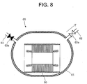
- FIG. 8 is a sectional elevational view illustrating the state at the first half of Step S50. That is, FIG. 8 is a sectional elevational view of the structure being evacuated in the first half of Step S50.
- the windings-incorporated object 90 is housed in a impregnation container 61 of an impregnator 60.
- the impregnation container 61 can be divided into upper and lower parts, for example, so as to allow the windings-incorporated object 90 to be put in and out thereof.
- the divided upper and lower parts of the impregnation container 61 can be connected by not-shown flange portions.
- a macromolecular polymer supply valve 63a on a macromolecular polymer supply pipe 63 and a vacuum exhaust valve 62a on a vacuum exhaust pipe 62 are closed to bring the impregnation container 61 into a sealed state.
- the vacuum exhaust valve 62a on the vacuum exhaust pipe 62 connected to, e.g., a vacuum pump (not illustrated) is opened to draw gas in the impregnation container 61.
- spaces in the main insulation tape 40 of the tape-wound conductor 50 in the windings-incorporated object 90 housed in the impregnation container 61 are also subjected to vacuum drawing.
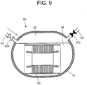
- FIG. 9 is a sectional elevational view of the state at the latter half of Step S50.
- the vacuum exhaust valve 62a on the vacuum exhaust pipe 62 is closed after the impregnation container 61 is subjected to vacuum drawing.
- the macromolecular polymer supply valve 63a on the macromolecular polymer supply pipe 63 is opened to supply the impregnating macromolecular polymer 47 into the impregnation container 61.
- the nanoparticle-containing impregnating macromolecular polymer 44 is supplied until the windings-incorporated object 90 is sufficiently impregnated with the nanoparticle-containing impregnating macromolecular polymer 44.
- the macromolecular polymer 44 is, for example, unsaturated polyester or epoxy resin.
- pressurized gas 65 is supplied from the macromolecular polymer supply pipe 63 into the impregnation container 61 to pressurize the impregnation container 61.
- inert gas having no reactivity with the impregnating macromolecular polymer 44 is used as the pressurized gas 65.
- impregnating macromolecular polymer 44 permeates the main insulation tape 40, the gap between the main insulating tapes 40, and the gap between main insulating tape and the corona discharge-preventing tape 80.
- the macromolecular polymer 44 that has impregnated is solidified. The solidification is achieved by heating the polymer if the polymer is a thermosetting resin such as epoxy resin.
- a corona discharge-preventing tape 80 is produced, in which the electrically conductive powder 82 and the non-electrically conductive nanoparticles 83 are dispersed in the fiber-reinforced cloth 81. Since the electrically conductive powder 82 is dispersed in the corona discharge-preventing tape 80, the tape 80 has semiconducting property. Further, since the electrically conductive powder 82 is so dispersed, the non-electrically conductive nanoparticles 83 are also dispersed, increasing anti-corona discharge property.
- non-electrically conductive nanoparticles 83 are mixed with the macromolecular polymer 84, the heat resistance will increase, and the anti-discharge property will also increase.
- the embodiment can achieve an advantage such as enhancement of the anti-corona discharge property of the insulation structure.
Landscapes
- Engineering & Computer Science (AREA)
- Power Engineering (AREA)
- Manufacturing & Machinery (AREA)
- Insulation, Fastening Of Motor, Generator Windings (AREA)
- Manufacture Of Motors, Generators (AREA)
Abstract
Description
- The present invention relates to a method for producing a corona discharge-preventing structure, a corona discharge-preventing structure, and a rotating electrical machine.
- When an unequal electric field portion occurs due to application of an electric field to an insulator, and the electric field at that portion exceeds an insulation-breakdown limit voltage, a local breakdown is caused there. When the local breakdown progresses dendritically, an electric tree is generated. The electric tree is believed to be generated by starting from a high electric field concentration parts such as an air gap or foreign matters between an electrode and an insulator, foreign matters, projections and voids in an insulator, and particularly in an air gap immediately under a corona discharge-preventing layer.
- The corona discharge-preventing layer is a part where semiconductor tapes are wound around the outermost layer to prevent corona discharge with making no air gap between overlapping layers of mica insulation tape, particularly in a case that insulation structures have high-voltage parts.
- In recent years, the use of inverters have been prevailing. In an inverter-driven motor, the lifetime of an insulating material of a coil conductive wire may be significantly reduced when the motor is used in a state where an impulse voltage including inverter surge repeatedly acts. Therefore, for example, such situation occurs, in which insulation for normal rated voltage 6.6 kV is forced to be used for an inverter-driven motor for rated voltage 3.3 kV. In such cases, corona discharge-preventing tapes are compelled to be used.
- As an example of an electrical insulating structure for a conductor used in a rotating electrical machine, a coil conductor is typically covered with an insulator having an insulating material. Such a conductor easily reaching high temperatures often has a mica electrical insulating structure using mica which is a kind of silicate minerals as an insulating material of high insulation class capable of withstanding comparatively high temperatures.
- As for the integrity of the insulating material, especially of the corona discharge-preventing layer, for example, IEC (International Electrotechnical Commission) is preparing for enactment of international standards prescribing a new insulation test method for accident prevention.
- Patent Document 1:
U.S. Published Application No. 2015/0101845-A1 - For example, the insulation lifetime of a formed-wound electrical motor for high voltage is significantly influenced by a main insulation and a turn insulation which are disposed inside a stator core. If such a problem occurs where the corona discharge-preventing layers are vanished, reliability of the electrical motor degrades remarkably. In such main insulations and turn insulations, the mica electrical insulating structure is often used.
- Further, the mica electrical insulating structure as the main insulation is formed, in most cases, by impregnating a mica insulating tape with epoxy resin. The mica insulating tape is composed of mica and an epoxy glass layer. The mica insulating tape thus configured is wound around a coil conductor and then impregnated with the epoxy resin, whereby insulation treatment by the mica electrical insulating structure is performed.
- Even if the structure including the outermost corona discharge-preventing layer has undergone the impregnation process, voids will be generated around a part of the corona discharge-preventing layer disposed outermost. At this part of the layer, discharge is likely to occur, and should better be made of material resistant to discharge.
- In some cases, however, the corona discharge cannot be suppressed so much as expected, due to the influence of the moisture in the environmental air.
- This invention has been made in view of the above. An object of the invention is to enhance the anti-corona discharge property in an insulation structure.
- According to the present invention, there is provided a method for producing a corona discharge-preventing structure for covering the outer surface of a to-be-insulated object, the method comprising: a tape producing step of producing a corona discharge-preventing tape including a macromolecular polymer added with an electrically conductive powder and non-electrically conductive nanoparticles; a main insulating step of winding a main insulating tape around the to-be-insulated object; and a winding step of winding the corona discharge-preventing tape around the outer surface of the to-be-insulated object around which the main insulating tape has been wound.
- According to the present invention, there is provided a corona discharge-preventing structure configured to prevent corona discharge in a to-be-insulated object, by covering the outer surface of the object, and comprising: a main insulating part provided on the outer surface of the to-be-insulated object; and a fiber-reinforced cloth shaped like tape and wound around the outer surface of the main insulating part; an electrically conductive powder dispersed in the fiber-reinforced cloth; and non-electrically conductive nanoparticles dispersed in the fiber-reinforced cloth.
- According to the present invention, there is provided a rotating electrical machine comprising: a rotor having an axially extending rotor shaft and a rotor core disposed radially outside the rotor shaft; a stator having a hollow cylindrical stator core disposed outside the rotor core via a gap, and stator winding conductors laid in a plurality of slots, the slots formed in an inner surface of the stator core with circumferential intervals therebetween and extending to axially both ends of the stator core; two bearings rotatably supporting the rotor shaft at both axial sides sandwiching the rotor core therebetween; a frame housing the rotor core and the stator; a main insulating part provided on each of the stator winding conductors to electrically insulate the stator winding conductors; and a corona discharge-preventing structure provided outside the main insulating part, wherein the corona discharge-preventing structure has: fiber-reinforced cloth shaped like a tape and wound around the outer surface of the main insulating part; an electrically conductive powder dispersed in the fiber-reinforced cloth; and non-electrically conductive nanoparticles dispersed in the fiber-reinforced cloth.
- According to the present invention, it is possible to enhance the anti-corona discharge property in an insulation structure.
-
-
FIG. 1 is a sectional longitudinal view illustrating the structure of a rotation electrical machine according to an embodiment. -
FIG. 2 is a perspective view explaining an insulation structure and a tape-wound conductor according to the embodiment. -
FIG. 3 is a flowchart showing a procedure of a method for producing an insulation structure according to the embodiment. -
FIG. 4 is a sectional elevational view illustrating the state in Step S11 of the method for producing the corona discharge-preventing tape. -
FIG. 5 is a sectional elevational view illustrating the state in Step S12 and Step S13 of the method for producing the corona discharge-preventing structure. -
FIG. 6 is a sectional longitudinal view showing the final state of an insulation structure according to this embodiment. -
FIG. 7 is a sectional longitudinal view showing a structure that incorporates the winding of a rotation electrical machine according to the embodiment. -
FIG. 8 is a sectional elevational view illustrating the state at the first half of Step S50. -
FIG. 9 is a sectional elevational view of the state at the latter half of Step S50. - Hereinafter, with reference to the accompanying drawings, a method for producing a corona discharge-preventing structure, a corona discharge-preventing structure, and a rotating electrical machine according to embodiments of the present invention will be described. The same or similar portions are represented by the same reference symbols and will not be described repeatedly.
- The followings exemplify the cases where an electrical insulating structure is applied to stator winding conductors of a rotating electrical machine. To-be-insulated objects or the objects to be insulated are not limited to the stator winding conductors. That is, it is applicable to any high voltage applied conductors as long as they have a structure where its outer surface is covered by the electrical insulating structure.
-
FIG. 1 is a sectional longitudinal view illustrating the structure of a rotation electrical machine according to an embodiment. The rotationelectrical machine 100 has arotor 10, astator 20, aframe 6 surrounding radially outside of therotor 10 and thestator 20, andbearing brackets 7 attached to the axial ends of theframe 6. - The
rotor 10 has arotor shaft 11 extending in its longitudinal direction and arotor core 12 attached to radially outside therotor shaft 11. Therotor shaft 11 is rotatably supported at both axial sides thereof bybearings 5. Each of thebearings 5 is stationarily supported by each of thebearing brackets 7. - The
stator 20 has astator core 21 disposed radially outside therotor core 12 so as to be spaced therefrom andstator windings 22 penetrating inside thestator core 21. - A plurality of stator slots (not illustrated) are formed along the inner surface of the
stator core 21 with circumferential intervals therebetween and extend up to axially both ends of thestator core 21. Conductors 24 (FIG. 2 ) for the stator winding 22 are disposed in each stator slot. -
FIG. 2 is a perspective view for explaining an electrical insulating structure and a tape-wound conductor according to the present embodiment. - The plurality of
stator winding conductors 24 constituting thestator windings 22 form a laminatedconductor 23. Specifically, sevenconductors 24 are arranged in one column, and two columns form the laminatedconductor 23 by fourteenconductors 24 in total. The number of laminated layers and the number of columns mentioned here are merely illustrative, and any number of theconductors 24 may be arranged in one or three or more columns. Eachstator winding conductor 24 is applied with aturn insulation 25 provided outside thereof. Accordingly, the outer surface of the laminatedconductor 23 is covered by theturn insulation 25. - A
main insulation tape 40 serving as a main insulation is wound outside the laminatedconductor 23 applied with theturn insulation 25 to form a main insulatedpart 49 outside the laminatedconductor 23, whereby a tape-wound conductor 50 is obtained. - Further, a corona discharge-preventing
tapes 80 are wound around the outermost layer. The corona discharge-preventingtapes 80 are used to equalize the potential of the surface of eachstator winding conductor 24 to the surface potential of thestator core 21, thereby to suppress the discharge between thestator winding conductors 24 and thestator core 21. - The corona discharge-preventing
tapes 80 are helically wound, with each turn contacting the immediately preceding turn as shown inFIG. 2 . Alternatively, thetape 80 may be wound, with each turn overlapping, in part, the immediately preceding turn. -
FIG. 3 is a flowchart showing a method for producing an insulation structure according to the present embodiment. - First, a corona discharge-preventing
tapes 80 are produced (Step S10). On the other hand, a maininsulating tapes 40 are wound around alaminated conductor 23 as a to-be-insulated object (Step S20). After performing Step S10 and Step S20, taping is performed, with winding the corona discharge-preventingtapes 80 around the wound main insulating tapes 40 (Step S30). Thereafter, laminatedconductors 23 wound with the corona discharge-preventingtape 80 are incorporated into thestator core 21, assembling a windings-incorporated object 90 (FIG. 8 ), which will be described later (Step S40). Then, the windings-incorporatedobject 90 so assembled is set in animpregnation apparatus 60. The windings-incorporatedobject 90 is impregnated with macromolecular polymer (Step S50). - Step S10 of the method for producing the corona discharge-preventing
tape 80 is described in detail below. - First, an electrically
conductive powder 82 and non-electricallyconductive nanoparticles 83 are mixed with amacromolecular polymer 84 to prepare a mixture (Step S11). Themacromolecular polymer 84 is, for example, unsaturated polyester or epoxy resin. -
FIG. 4 is a sectional elevational view illustrating the state in Step S11 of the method for producing the corona discharge-preventing tape. As shown inFIG. 4 , the electricallyconductive powder 82 and the non-electricallyconductive nanoparticles 83 are added to themacromolecular polymer 84 stored in astorage vessel 87. While the electricallyconductive powder 82 and non-electricallyconductive nanoparticles 83 are being added, themacromolecular polymer 84 is stirred by astirring blade 87a. Mixture 85 (FIG. 5 ) is thereby produced. - The
macromolecular polymer 84 may be replaced by, for example, varnish prepared by dissolving themacromolecular polymer 84 in a solvent. - As the electrically
conductive powder 82, carbon black, for example, can be utilized. Carbon black is fine carbon particles having a diameter of about 3 nm to 500 nm, and is industrially produced. The electricallyconductive powder 82 is not limited to carbon black, nonetheless. It may be other electrically conductive substance such as carbon nanotube. The electricallyconductive powder 82 is added to themacromolecular polymer 84 which is electrically insulating and also dielectric, forming a low-resistance material of, for example, about 100 Ω·cm. The low-resistance material can have the same potential as the core, preventing discharge between the main insulating tape and thestator core 22. - Generally, the nanoparticles are said to include particles having a diameter of up to about 100 nm. The nanoparticles used in the present embodiment are assumed to be particles having a diameter of 100 nm or less, i.e., about several tens of nm. Here, particles having a diameter equal to or less than 100 nm shall be referred to as "nanoparticles."
- As non-electrically
conductive nanoparticles 83, particles of, for example, silicon dioxide (SiO2), aluminum oxide (Al2O3), magnesium oxide (MgO) or boron nitride (BN), which are electrically non-electrically conductive substances, can be utilized. - Particles having a diameter of 100 nm or less may be produced by chemical growth from finer ones. Alternatively, particles having a diameter exceeding 100 nm may be pulverized to produce particles having a diameter of 100 nm or less. Further, surface modification may be applied so as to prevent particle aggregation in the
macromolecular polymer 84. - Next, the
mixture 85 is coated on fiber-reinforced cloth 81 (Step S12). The fiber-reinforcedcloth 81 is, for example, glass cloth.FIG. 5 is a sectional elevational view illustrating the state in Step S12 and Step S13 of the method for producing the corona discharge-preventing structure. The fiber-reinforcedcloth 81 is impregnated with themixture 85 produced in thestorage vessel 87. As a result, themixture 85 adheres in the fiber-reinforcedcloth 81 and to the surface thereof. The fiber-reinforcedcloth 81 now having themixture 85 thereon and therein is squeezed byrollers surplus mixture 85 drips down and is collected in areceptacle 87b and returns into thestorage vessel 87. - Then, the fiber-reinforced
cloth 81 to which themixture 85 is adhered is sent to a heating/drying apparatus 88. The heating/drying apparatus 88 heats and dries the fiber-reinforcedcloth 81. As a result, a corona discharge-preventingcloth 86 is produced (Step S13). - Next, the corona discharge-preventing
cloth 86 is cut into corona discharge-preventing tapes 80 (FIG. 6 ) (Step S14). -
FIG. 6 is a sectional longitudinal view showing the final state of an insulation structure according to this embodiment. The maininsulating tapes 40 are wound around thelaminated conductor 23, forming two layers. Further, the corona discharge-preventingtape 80 is wound around the maininsulating tapes 40. - The corona discharge-preventing
tape 80 is wound not to space the turns of the main insulatingtape 40 in the direction the turns lie one another. The corona discharge-preventingtape 80 is so wound that they may tighten the maininsulating tapes 40 from outward. Once the corona discharge-preventingtape 80 has been wound so, the resultant structure is impregnated with themacromolecular polymer 84. -
FIG. 7 is a sectional longitudinal view showing a structure that incorporates the windings of a rotation electrical machine according to the embodiment. The windings-incorporatedobject 90 has thestator core 21, thestator windings 22 and theframe 6 disposed radially outside thestator core 21 and thestator windings 22. - The
stator windings 22 are formed by connecting the tape-wound conductors 50 (FIG. 2 ) housed in the plurality of slots (not illustrated). The slots are formed in the inner surface of thestator core 21 with circumferential intervals therebetween and extend up to the both axial ends of thestator core 21. - Then, the windings-incorporated
object 90 is impregnated with macromolecular polymer, and the macromolecular polymer is solidified (Step S50).FIG. 8 is a sectional elevational view illustrating the state at the first half of Step S50. That is,FIG. 8 is a sectional elevational view of the structure being evacuated in the first half of Step S50. Specifically, the windings-incorporatedobject 90 is housed in aimpregnation container 61 of animpregnator 60. Theimpregnation container 61 can be divided into upper and lower parts, for example, so as to allow the windings-incorporatedobject 90 to be put in and out thereof. The divided upper and lower parts of theimpregnation container 61 can be connected by not-shown flange portions. - A macromolecular
polymer supply valve 63a on a macromolecularpolymer supply pipe 63 and avacuum exhaust valve 62a on avacuum exhaust pipe 62 are closed to bring theimpregnation container 61 into a sealed state. After that, thevacuum exhaust valve 62a on thevacuum exhaust pipe 62 connected to, e.g., a vacuum pump (not illustrated) is opened to draw gas in theimpregnation container 61. As a result, spaces in themain insulation tape 40 of the tape-wound conductor 50 in the windings-incorporatedobject 90 housed in theimpregnation container 61 are also subjected to vacuum drawing. -
FIG. 9 is a sectional elevational view of the state at the latter half of Step S50. Thevacuum exhaust valve 62a on thevacuum exhaust pipe 62 is closed after theimpregnation container 61 is subjected to vacuum drawing. Then, the macromolecularpolymer supply valve 63a on the macromolecularpolymer supply pipe 63 is opened to supply the impregnating macromolecular polymer 47 into theimpregnation container 61. The nanoparticle-containing impregnatingmacromolecular polymer 44 is supplied until the windings-incorporatedobject 90 is sufficiently impregnated with the nanoparticle-containing impregnatingmacromolecular polymer 44. Themacromolecular polymer 44 is, for example, unsaturated polyester or epoxy resin. - When a state is reached where the windings-incorporated
object 90 is sufficiently impregnated with the impregnatingmacromolecular polymer 44,pressurized gas 65 is supplied from the macromolecularpolymer supply pipe 63 into theimpregnation container 61 to pressurize theimpregnation container 61. For example, inert gas having no reactivity with the impregnatingmacromolecular polymer 44 is used as thepressurized gas 65. As a result, impregnatingmacromolecular polymer 44 permeates themain insulation tape 40, the gap between the maininsulating tapes 40, and the gap between main insulating tape and the corona discharge-preventingtape 80. Thereafter, themacromolecular polymer 44 that has impregnated is solidified. The solidification is achieved by heating the polymer if the polymer is a thermosetting resin such as epoxy resin. - After the sequence described above, a corona discharge-preventing
tape 80 is produced, in which the electricallyconductive powder 82 and the non-electricallyconductive nanoparticles 83 are dispersed in the fiber-reinforcedcloth 81. Since the electricallyconductive powder 82 is dispersed in the corona discharge-preventingtape 80, thetape 80 has semiconducting property. Further, since the electricallyconductive powder 82 is so dispersed, the non-electricallyconductive nanoparticles 83 are also dispersed, increasing anti-corona discharge property. - This part is likely to undergo discharge, and should therefore be made of material resistant to discharge. If the non-electrically
conductive nanoparticles 83 are mixed with themacromolecular polymer 84, the heat resistance will increase, and the anti-discharge property will also increase. - As stated above, the embodiment can achieve an advantage such as enhancement of the anti-corona discharge property of the insulation structure.
- While the embodiment of the present inventions has been described, the embodiment has been presented by way of example only, and is not intended to limit the scope of the invention. Furthermore, the above-described embodiments may be put to use in various different ways and, if appropriate, any of the components thereof may be omitted, replaced or altered in various different ways without departing from the spirit and scope of the invention.
- All the above-described embodiments and the modifications made to them are within the spirit and scope of the present invention, which is specifically defined by the appended claims, as well as their equivalents.
- 5: bearing, 6: frame, 7: bearing bracket, 10: rotor, 11: rotor shaft, 12: rotor core, 20: stator, 21: stator core, 22: stator winding, 23: laminated conductor, 24: stator winding conductor, 25: turn insulator, 30: insulation structure, 40: main insulating tape, 41: main insulation layer, 42: fiber reinforcement part, 43: joining macromolecular polymer, 47: impregnating macromolecular polymer, 49: main insulation part, 50: tape-wound conductor, 60: impregnation apparatus, 61: vessel, 62: evacuation pipe, 62a: evacuation valve, 63: macromolecular polymer supply pipe, 63a: macromolecular polymer supply valve, 65: pressurized gas, 80: corona discharge-preventing tape, 81: fiber-reinforced cloth, 82: electrically conductive powder, 83: non-electrically conductive nanoparticle, 84: macromolecular polymer, 85: mixture, 86: corona discharge-preventing cloth, 87: storage vessel, 87a: stirring blade, 87b: receptacle, 88: heating/drying apparatus, 89a, 89b: roller, 100: rotation electrical machine
Claims (8)
- A method for producing a corona discharge-preventing structure for covering outer surface of a to-be-insulated object, the method comprising:a tape producing step of producing a corona discharge-preventing tape including a macromolecular polymer added with an electrically conductive powder and non-electrically conductive nanoparticles;a main insulating step of winding a main insulating tape around the to-be-insulated object; anda winding step of winding the corona discharge-preventing tape around the outer surface of the to-be-insulated object around which the main insulating tape has been wound.
- The method for producing a corona discharge-preventing structure, according to claim 1, wherein the tape producing step has:a mixture producing step of producing a mixture by adding the electrically conductive powder and the non-electrically conductive nanoparticles to the macromolecular polymer;a coating step of coating the mixture on a fiber-reinforced cloth;a heating-drying step of heating and drying the fiber-reinforced cloth coated with the mixture; anda cutting step of cutting the fiber-reinforced cloth into tapes after the heating-drying step, thereby providing a fiber-reinforced tape.
- The method for producing a corona discharge-preventing structure, according to claim 2, wherein
the fiber-reinforced cloth is glass cloth. - The method for producing a corona discharge-preventing structure, according to claim 2 or claim 3, wherein
the coating step has a step of passing the fiber-reinforced cloth in a liquid-state resin in which carbon black and the non-electrically conductive nanoparticles are mixed together. - The method for producing a corona discharge-preventing structure, according to any one of claims 1 to 4, wherein
the non-electrically conductive nanoparticles are at least one type selected from a group consisting of silicon dioxide, aluminum oxide, magnesium oxide, boron nitride and carbon nanotubes. - The method for producing a corona discharge-preventing structure, according to any one of claims 1 to 5, wherein
the electrically conductive powder is carbon black. - A corona discharge-preventing structure configured to prevent corona discharge in a to-be-insulated object, by covering the outer surface of the object, the structure comprising:a main insulating part provided on the outer surface of the to-be-insulated object; anda fiber-reinforced cloth shaped in a tape and wound around the outer surface of the main insulating part;an electrically conductive powder dispersed in the fiber-reinforced cloth; andnon-electrically conductive nanoparticles dispersed in the fiber-reinforced cloth.
- A rotating electrical machine comprising:a rotor having an axially extending rotor shaft and a rotor core disposed radially outside the rotor shaft;a stator having a hollow cylindrical stator core disposed outside the rotor core via a gap, and stator winding conductors laid in a plurality of slots, the slots formed in an inner surface of the stator core with circumferential intervals therebetween and extending to axially both ends of the stator core;two bearings rotatably supporting the rotor shaft at both axial sides sandwiching the rotor core therebetween;a frame housing the rotor core and the stator;a main insulating part provided on each of the stator winding conductors to electrically insulate the stator winding conductors; anda corona discharge-preventing structure provided outside the main insulating part, whereinthe corona discharge-preventing structure has:a fiber-reinforced cloth shaped like a tape and wound around the outer surface of the main insulating part;an electrically conductive powder dispersed in the fiber-reinforced cloth; andnon-electrically conductive nanoparticles dispersed in the fiber-reinforced cloth.
Applications Claiming Priority (1)
| Application Number | Priority Date | Filing Date | Title |
|---|---|---|---|
| PCT/JP2016/003167 WO2018002974A1 (en) | 2016-07-01 | 2016-07-01 | Method for producing corona discharge-preventing structure, corona discharge-preventing structure, and rotating electrical machine |
Publications (3)
| Publication Number | Publication Date |
|---|---|
| EP3480923A1 true EP3480923A1 (en) | 2019-05-08 |
| EP3480923A4 EP3480923A4 (en) | 2020-01-08 |
| EP3480923B1 EP3480923B1 (en) | 2022-04-27 |
Family
ID=60786184
Family Applications (1)
| Application Number | Title | Priority Date | Filing Date |
|---|---|---|---|
| EP16907209.7A Active EP3480923B1 (en) | 2016-07-01 | 2016-07-01 | Method for producing corona discharge-preventing structure, corona discharge-preventing structure, and rotating electrical machine |
Country Status (5)
| Country | Link |
|---|---|
| US (1) | US20190149006A1 (en) |
| EP (1) | EP3480923B1 (en) |
| JP (1) | JPWO2018002974A1 (en) |
| CN (1) | CN109075644A (en) |
| WO (1) | WO2018002974A1 (en) |
Families Citing this family (5)
| Publication number | Priority date | Publication date | Assignee | Title |
|---|---|---|---|---|
| EP3240150A1 (en) * | 2016-04-25 | 2017-11-01 | Siemens Aktiengesellschaft | Electrical machine and method for dismantling and assembling the electric machine |
| US12470103B2 (en) | 2021-03-23 | 2025-11-11 | Mitsubishi Electric Corporation | Semiconductive member, stator coil, and rotating electric machine |
| JP7801931B2 (en) * | 2022-03-30 | 2026-01-19 | 三菱重工業株式会社 | Coil wire, coil wire manufacturing method, stator, and electric motor |
| CN119010495B (en) * | 2024-08-21 | 2025-09-05 | 湖南中车尚驱电气有限公司 | Alpha coil insulation wrapping and sealing method |
| CN119891612B (en) * | 2025-03-27 | 2025-07-22 | 华北电力大学 | An environmentally friendly motor with anti-corona aging and a manufacturing method thereof |
Family Cites Families (11)
| Publication number | Priority date | Publication date | Assignee | Title |
|---|---|---|---|---|
| JP3653901B2 (en) * | 1996-12-10 | 2005-06-02 | 富士電機システムズ株式会社 | Rotator stator coil |
| US20070149073A1 (en) * | 2002-06-18 | 2007-06-28 | Siemens Aktiengesellschaft | Electric machine with a corona shield |
| US20040182596A1 (en) * | 2003-03-17 | 2004-09-23 | Sedlak John Michael | Method and apparatus for insulating magnet wire |
| JP2006246599A (en) * | 2005-03-02 | 2006-09-14 | Toshiba Corp | Semiconductive tape, method for producing semiconductive tape, insulating coil, and rotating electric machine |
| JP2007174816A (en) * | 2005-12-22 | 2007-07-05 | Mitsubishi Electric Corp | Stator for rotating electric machine and method for manufacturing the same |
| US7459817B2 (en) * | 2006-08-15 | 2008-12-02 | Bombardier Transportation Gmbh | Semi-enclosed AC motor |
| US8288911B2 (en) * | 2006-12-15 | 2012-10-16 | General Electric Company | Non-linear dielectrics used as electrical insulation for rotating electrical machinery |
| DE102011083409A1 (en) | 2011-09-26 | 2013-03-28 | Siemens Aktiengesellschaft | Insulating systems with improved partial discharge resistance, process for the preparation thereof |
| EP2645374A1 (en) * | 2012-03-26 | 2013-10-02 | Siemens Aktiengesellschaft | Two-layer high-voltage insulation system and electric machine |
| EP3046117A4 (en) * | 2013-10-09 | 2017-05-17 | Hitachi Chemical Co., Ltd. | Prepreg mica tape and coil using same |
| JPWO2016104141A1 (en) * | 2014-12-22 | 2017-04-27 | 三菱電機株式会社 | Insulating tape and manufacturing method thereof, stator coil and manufacturing method thereof, and generator |
-
2016
- 2016-07-01 EP EP16907209.7A patent/EP3480923B1/en active Active
- 2016-07-01 WO PCT/JP2016/003167 patent/WO2018002974A1/en not_active Ceased
- 2016-07-01 JP JP2018524587A patent/JPWO2018002974A1/en active Pending
- 2016-07-01 CN CN201680084498.1A patent/CN109075644A/en active Pending
-
2018
- 2018-12-20 US US16/227,840 patent/US20190149006A1/en not_active Abandoned
Also Published As
| Publication number | Publication date |
|---|---|
| US20190149006A1 (en) | 2019-05-16 |
| JPWO2018002974A1 (en) | 2019-04-18 |
| EP3480923A4 (en) | 2020-01-08 |
| CN109075644A (en) | 2018-12-21 |
| WO2018002974A1 (en) | 2018-01-04 |
| EP3480923B1 (en) | 2022-04-27 |
Similar Documents
| Publication | Publication Date | Title |
|---|---|---|
| US20190149006A1 (en) | Method for producing corona discharge-preventing structure, corona discharge-preventing structure, and rotating electrical machine | |
| EP3480919B1 (en) | Method for producing electrical insulating structure | |
| US10931159B2 (en) | Electrical insulating structure producing method, electrical insulating structure and rotating electrical machine | |
| US10938260B2 (en) | Electrical insulating structure producing method, electrical insulating structure and rotating electrical machine | |
| US10903710B2 (en) | Producing method for electrical insulating structure, electrical insulating structure and rotating electrical machine | |
| KR102813731B1 (en) | Method for manufacturing resin and method for manufacturing insulating structure | |
| US12168722B2 (en) | Method of producing resin and method of producing insulating structure | |
| EP4492643A1 (en) | Rotating electric machine and insulation tape | |
| JP2023158851A (en) | Resin manufacturing method and insulation structure manufacturing method | |
| HK40092092A (en) | Method of producing resin and method of producing insulating structure |
Legal Events
| Date | Code | Title | Description |
|---|---|---|---|
| STAA | Information on the status of an ep patent application or granted ep patent |
Free format text: STATUS: THE INTERNATIONAL PUBLICATION HAS BEEN MADE |
|
| PUAI | Public reference made under article 153(3) epc to a published international application that has entered the european phase |
Free format text: ORIGINAL CODE: 0009012 |
|
| STAA | Information on the status of an ep patent application or granted ep patent |
Free format text: STATUS: REQUEST FOR EXAMINATION WAS MADE |
|
| 17P | Request for examination filed |
Effective date: 20190131 |
|
| AK | Designated contracting states |
Kind code of ref document: A1 Designated state(s): AL AT BE BG CH CY CZ DE DK EE ES FI FR GB GR HR HU IE IS IT LI LT LU LV MC MK MT NL NO PL PT RO RS SE SI SK SM TR |
|
| AX | Request for extension of the european patent |
Extension state: BA ME |
|
| DAV | Request for validation of the european patent (deleted) | ||
| DAX | Request for extension of the european patent (deleted) | ||
| A4 | Supplementary search report drawn up and despatched |
Effective date: 20191206 |
|
| RIC1 | Information provided on ipc code assigned before grant |
Ipc: H02K 15/10 20060101ALI20191202BHEP Ipc: H01B 13/004 20060101ALI20191202BHEP Ipc: H02K 3/40 20060101ALI20191202BHEP Ipc: H02K 3/30 20060101AFI20191202BHEP |
|
| GRAP | Despatch of communication of intention to grant a patent |
Free format text: ORIGINAL CODE: EPIDOSNIGR1 |
|
| STAA | Information on the status of an ep patent application or granted ep patent |
Free format text: STATUS: GRANT OF PATENT IS INTENDED |
|
| INTG | Intention to grant announced |
Effective date: 20210608 |
|
| GRAJ | Information related to disapproval of communication of intention to grant by the applicant or resumption of examination proceedings by the epo deleted |
Free format text: ORIGINAL CODE: EPIDOSDIGR1 |
|
| STAA | Information on the status of an ep patent application or granted ep patent |
Free format text: STATUS: REQUEST FOR EXAMINATION WAS MADE |
|
| INTC | Intention to grant announced (deleted) | ||
| GRAP | Despatch of communication of intention to grant a patent |
Free format text: ORIGINAL CODE: EPIDOSNIGR1 |
|
| STAA | Information on the status of an ep patent application or granted ep patent |
Free format text: STATUS: GRANT OF PATENT IS INTENDED |
|
| INTG | Intention to grant announced |
Effective date: 20211130 |
|
| GRAS | Grant fee paid |
Free format text: ORIGINAL CODE: EPIDOSNIGR3 |
|
| GRAA | (expected) grant |
Free format text: ORIGINAL CODE: 0009210 |
|
| STAA | Information on the status of an ep patent application or granted ep patent |
Free format text: STATUS: THE PATENT HAS BEEN GRANTED |
|
| AK | Designated contracting states |
Kind code of ref document: B1 Designated state(s): AL AT BE BG CH CY CZ DE DK EE ES FI FR GB GR HR HU IE IS IT LI LT LU LV MC MK MT NL NO PL PT RO RS SE SI SK SM TR |
|
| RAP3 | Party data changed (applicant data changed or rights of an application transferred) |
Owner name: TOSHIBA MITSUBISHI-ELECTRIC INDUSTRIAL SYSTEMS CORPORATION |
|
| REG | Reference to a national code |
Ref country code: GB Ref legal event code: FG4D |
|
| REG | Reference to a national code |
Ref country code: CH Ref legal event code: EP |
|
| REG | Reference to a national code |
Ref country code: AT Ref legal event code: REF Ref document number: 1487730 Country of ref document: AT Kind code of ref document: T Effective date: 20220515 |
|
| REG | Reference to a national code |
Ref country code: DE Ref legal event code: R096 Ref document number: 602016071620 Country of ref document: DE |
|
| REG | Reference to a national code |
Ref country code: IE Ref legal event code: FG4D |
|
| REG | Reference to a national code |
Ref country code: SE Ref legal event code: TRGR |
|
| REG | Reference to a national code |
Ref country code: LT Ref legal event code: MG9D |
|
| REG | Reference to a national code |
Ref country code: NL Ref legal event code: MP Effective date: 20220427 |
|
| REG | Reference to a national code |
Ref country code: AT Ref legal event code: MK05 Ref document number: 1487730 Country of ref document: AT Kind code of ref document: T Effective date: 20220427 |
|
| PG25 | Lapsed in a contracting state [announced via postgrant information from national office to epo] |
Ref country code: NL Free format text: LAPSE BECAUSE OF FAILURE TO SUBMIT A TRANSLATION OF THE DESCRIPTION OR TO PAY THE FEE WITHIN THE PRESCRIBED TIME-LIMIT Effective date: 20220427 |
|
| PG25 | Lapsed in a contracting state [announced via postgrant information from national office to epo] |
Ref country code: PT Free format text: LAPSE BECAUSE OF FAILURE TO SUBMIT A TRANSLATION OF THE DESCRIPTION OR TO PAY THE FEE WITHIN THE PRESCRIBED TIME-LIMIT Effective date: 20220829 Ref country code: NO Free format text: LAPSE BECAUSE OF FAILURE TO SUBMIT A TRANSLATION OF THE DESCRIPTION OR TO PAY THE FEE WITHIN THE PRESCRIBED TIME-LIMIT Effective date: 20220727 Ref country code: LT Free format text: LAPSE BECAUSE OF FAILURE TO SUBMIT A TRANSLATION OF THE DESCRIPTION OR TO PAY THE FEE WITHIN THE PRESCRIBED TIME-LIMIT Effective date: 20220427 Ref country code: HR Free format text: LAPSE BECAUSE OF FAILURE TO SUBMIT A TRANSLATION OF THE DESCRIPTION OR TO PAY THE FEE WITHIN THE PRESCRIBED TIME-LIMIT Effective date: 20220427 Ref country code: GR Free format text: LAPSE BECAUSE OF FAILURE TO SUBMIT A TRANSLATION OF THE DESCRIPTION OR TO PAY THE FEE WITHIN THE PRESCRIBED TIME-LIMIT Effective date: 20220728 Ref country code: FI Free format text: LAPSE BECAUSE OF FAILURE TO SUBMIT A TRANSLATION OF THE DESCRIPTION OR TO PAY THE FEE WITHIN THE PRESCRIBED TIME-LIMIT Effective date: 20220427 Ref country code: ES Free format text: LAPSE BECAUSE OF FAILURE TO SUBMIT A TRANSLATION OF THE DESCRIPTION OR TO PAY THE FEE WITHIN THE PRESCRIBED TIME-LIMIT Effective date: 20220427 Ref country code: BG Free format text: LAPSE BECAUSE OF FAILURE TO SUBMIT A TRANSLATION OF THE DESCRIPTION OR TO PAY THE FEE WITHIN THE PRESCRIBED TIME-LIMIT Effective date: 20220727 Ref country code: AT Free format text: LAPSE BECAUSE OF FAILURE TO SUBMIT A TRANSLATION OF THE DESCRIPTION OR TO PAY THE FEE WITHIN THE PRESCRIBED TIME-LIMIT Effective date: 20220427 |
|
| PG25 | Lapsed in a contracting state [announced via postgrant information from national office to epo] |
Ref country code: RS Free format text: LAPSE BECAUSE OF FAILURE TO SUBMIT A TRANSLATION OF THE DESCRIPTION OR TO PAY THE FEE WITHIN THE PRESCRIBED TIME-LIMIT Effective date: 20220427 Ref country code: PL Free format text: LAPSE BECAUSE OF FAILURE TO SUBMIT A TRANSLATION OF THE DESCRIPTION OR TO PAY THE FEE WITHIN THE PRESCRIBED TIME-LIMIT Effective date: 20220427 Ref country code: LV Free format text: LAPSE BECAUSE OF FAILURE TO SUBMIT A TRANSLATION OF THE DESCRIPTION OR TO PAY THE FEE WITHIN THE PRESCRIBED TIME-LIMIT Effective date: 20220427 Ref country code: IS Free format text: LAPSE BECAUSE OF FAILURE TO SUBMIT A TRANSLATION OF THE DESCRIPTION OR TO PAY THE FEE WITHIN THE PRESCRIBED TIME-LIMIT Effective date: 20220827 |
|
| REG | Reference to a national code |
Ref country code: DE Ref legal event code: R097 Ref document number: 602016071620 Country of ref document: DE |
|
| PG25 | Lapsed in a contracting state [announced via postgrant information from national office to epo] |
Ref country code: SM Free format text: LAPSE BECAUSE OF FAILURE TO SUBMIT A TRANSLATION OF THE DESCRIPTION OR TO PAY THE FEE WITHIN THE PRESCRIBED TIME-LIMIT Effective date: 20220427 Ref country code: SK Free format text: LAPSE BECAUSE OF FAILURE TO SUBMIT A TRANSLATION OF THE DESCRIPTION OR TO PAY THE FEE WITHIN THE PRESCRIBED TIME-LIMIT Effective date: 20220427 Ref country code: RO Free format text: LAPSE BECAUSE OF FAILURE TO SUBMIT A TRANSLATION OF THE DESCRIPTION OR TO PAY THE FEE WITHIN THE PRESCRIBED TIME-LIMIT Effective date: 20220427 Ref country code: EE Free format text: LAPSE BECAUSE OF FAILURE TO SUBMIT A TRANSLATION OF THE DESCRIPTION OR TO PAY THE FEE WITHIN THE PRESCRIBED TIME-LIMIT Effective date: 20220427 Ref country code: DK Free format text: LAPSE BECAUSE OF FAILURE TO SUBMIT A TRANSLATION OF THE DESCRIPTION OR TO PAY THE FEE WITHIN THE PRESCRIBED TIME-LIMIT Effective date: 20220427 Ref country code: CZ Free format text: LAPSE BECAUSE OF FAILURE TO SUBMIT A TRANSLATION OF THE DESCRIPTION OR TO PAY THE FEE WITHIN THE PRESCRIBED TIME-LIMIT Effective date: 20220427 |
|
| PG25 | Lapsed in a contracting state [announced via postgrant information from national office to epo] |
Ref country code: MC Free format text: LAPSE BECAUSE OF FAILURE TO SUBMIT A TRANSLATION OF THE DESCRIPTION OR TO PAY THE FEE WITHIN THE PRESCRIBED TIME-LIMIT Effective date: 20220427 |
|
| PLBE | No opposition filed within time limit |
Free format text: ORIGINAL CODE: 0009261 |
|
| STAA | Information on the status of an ep patent application or granted ep patent |
Free format text: STATUS: NO OPPOSITION FILED WITHIN TIME LIMIT |
|
| GBPC | Gb: european patent ceased through non-payment of renewal fee |
Effective date: 20220727 |
|
| PG25 | Lapsed in a contracting state [announced via postgrant information from national office to epo] |
Ref country code: AL Free format text: LAPSE BECAUSE OF FAILURE TO SUBMIT A TRANSLATION OF THE DESCRIPTION OR TO PAY THE FEE WITHIN THE PRESCRIBED TIME-LIMIT Effective date: 20220427 |
|
| 26N | No opposition filed |
Effective date: 20230130 |
|
| PG25 | Lapsed in a contracting state [announced via postgrant information from national office to epo] |
Ref country code: LU Free format text: LAPSE BECAUSE OF NON-PAYMENT OF DUE FEES Effective date: 20220701 |
|
| PG25 | Lapsed in a contracting state [announced via postgrant information from national office to epo] |
Ref country code: SI Free format text: LAPSE BECAUSE OF FAILURE TO SUBMIT A TRANSLATION OF THE DESCRIPTION OR TO PAY THE FEE WITHIN THE PRESCRIBED TIME-LIMIT Effective date: 20220427 Ref country code: GB Free format text: LAPSE BECAUSE OF NON-PAYMENT OF DUE FEES Effective date: 20220727 |
|
| PG25 | Lapsed in a contracting state [announced via postgrant information from national office to epo] |
Ref country code: IE Free format text: LAPSE BECAUSE OF NON-PAYMENT OF DUE FEES Effective date: 20220701 |
|
| PG25 | Lapsed in a contracting state [announced via postgrant information from national office to epo] |
Ref country code: IT Free format text: LAPSE BECAUSE OF FAILURE TO SUBMIT A TRANSLATION OF THE DESCRIPTION OR TO PAY THE FEE WITHIN THE PRESCRIBED TIME-LIMIT Effective date: 20220427 |
|
| PG25 | Lapsed in a contracting state [announced via postgrant information from national office to epo] |
Ref country code: HU Free format text: LAPSE BECAUSE OF FAILURE TO SUBMIT A TRANSLATION OF THE DESCRIPTION OR TO PAY THE FEE WITHIN THE PRESCRIBED TIME-LIMIT; INVALID AB INITIO Effective date: 20160701 |
|
| PG25 | Lapsed in a contracting state [announced via postgrant information from national office to epo] |
Ref country code: MK Free format text: LAPSE BECAUSE OF FAILURE TO SUBMIT A TRANSLATION OF THE DESCRIPTION OR TO PAY THE FEE WITHIN THE PRESCRIBED TIME-LIMIT Effective date: 20220427 Ref country code: CY Free format text: LAPSE BECAUSE OF FAILURE TO SUBMIT A TRANSLATION OF THE DESCRIPTION OR TO PAY THE FEE WITHIN THE PRESCRIBED TIME-LIMIT Effective date: 20220427 |
|
| PG25 | Lapsed in a contracting state [announced via postgrant information from national office to epo] |
Ref country code: MT Free format text: LAPSE BECAUSE OF FAILURE TO SUBMIT A TRANSLATION OF THE DESCRIPTION OR TO PAY THE FEE WITHIN THE PRESCRIBED TIME-LIMIT Effective date: 20220427 |
|
| PG25 | Lapsed in a contracting state [announced via postgrant information from national office to epo] |
Ref country code: BG Free format text: LAPSE BECAUSE OF FAILURE TO SUBMIT A TRANSLATION OF THE DESCRIPTION OR TO PAY THE FEE WITHIN THE PRESCRIBED TIME-LIMIT Effective date: 20220427 |
|
| PG25 | Lapsed in a contracting state [announced via postgrant information from national office to epo] |
Ref country code: BG Free format text: LAPSE BECAUSE OF FAILURE TO SUBMIT A TRANSLATION OF THE DESCRIPTION OR TO PAY THE FEE WITHIN THE PRESCRIBED TIME-LIMIT Effective date: 20220427 |
|
| PGFP | Annual fee paid to national office [announced via postgrant information from national office to epo] |
Ref country code: BE Payment date: 20250619 Year of fee payment: 10 |
|
| PGFP | Annual fee paid to national office [announced via postgrant information from national office to epo] |
Ref country code: FR Payment date: 20250610 Year of fee payment: 10 |
|
| PGFP | Annual fee paid to national office [announced via postgrant information from national office to epo] |
Ref country code: SE Payment date: 20250528 Year of fee payment: 10 |
|
| PGFP | Annual fee paid to national office [announced via postgrant information from national office to epo] |
Ref country code: DE Payment date: 20250528 Year of fee payment: 10 |
|
| PGFP | Annual fee paid to national office [announced via postgrant information from national office to epo] |
Ref country code: CH Payment date: 20250801 Year of fee payment: 10 |
|
| PG25 | Lapsed in a contracting state [announced via postgrant information from national office to epo] |
Ref country code: TR Free format text: LAPSE BECAUSE OF FAILURE TO SUBMIT A TRANSLATION OF THE DESCRIPTION OR TO PAY THE FEE WITHIN THE PRESCRIBED TIME-LIMIT Effective date: 20220427 |