EP3480672A1 - Verfahren zum erkennen und anzeigen von operator-zugriffen auf prozessobjekte sowie operator-system - Google Patents
Verfahren zum erkennen und anzeigen von operator-zugriffen auf prozessobjekte sowie operator-system Download PDFInfo
- Publication number
- EP3480672A1 EP3480672A1 EP17200152.1A EP17200152A EP3480672A1 EP 3480672 A1 EP3480672 A1 EP 3480672A1 EP 17200152 A EP17200152 A EP 17200152A EP 3480672 A1 EP3480672 A1 EP 3480672A1
- Authority
- EP
- European Patent Office
- Prior art keywords
- operator
- image
- objects
- belonging
- component
- Prior art date
- Legal status (The legal status is an assumption and is not a legal conclusion. Google has not performed a legal analysis and makes no representation as to the accuracy of the status listed.)
- Granted
Links
- 238000000034 method Methods 0.000 title claims abstract description 118
- 238000004886 process control Methods 0.000 claims abstract description 24
- 238000012544 monitoring process Methods 0.000 claims description 4
- 239000003550 marker Substances 0.000 claims description 3
- 238000011112 process operation Methods 0.000 description 3
- 238000012545 processing Methods 0.000 description 3
- 238000004891 communication Methods 0.000 description 2
- 238000012369 In process control Methods 0.000 description 1
- 238000010923 batch production Methods 0.000 description 1
- 230000001419 dependent effect Effects 0.000 description 1
- 238000005516 engineering process Methods 0.000 description 1
- 230000012447 hatching Effects 0.000 description 1
- 238000010965 in-process control Methods 0.000 description 1
- 230000002093 peripheral effect Effects 0.000 description 1
- 238000012546 transfer Methods 0.000 description 1
Images


Classifications
-
- G—PHYSICS
- G05—CONTROLLING; REGULATING
- G05B—CONTROL OR REGULATING SYSTEMS IN GENERAL; FUNCTIONAL ELEMENTS OF SUCH SYSTEMS; MONITORING OR TESTING ARRANGEMENTS FOR SUCH SYSTEMS OR ELEMENTS
- G05B19/00—Programme-control systems
- G05B19/02—Programme-control systems electric
- G05B19/04—Programme control other than numerical control, i.e. in sequence controllers or logic controllers
- G05B19/042—Programme control other than numerical control, i.e. in sequence controllers or logic controllers using digital processors
- G05B19/0426—Programming the control sequence
-
- G—PHYSICS
- G05—CONTROLLING; REGULATING
- G05B—CONTROL OR REGULATING SYSTEMS IN GENERAL; FUNCTIONAL ELEMENTS OF SUCH SYSTEMS; MONITORING OR TESTING ARRANGEMENTS FOR SUCH SYSTEMS OR ELEMENTS
- G05B23/00—Testing or monitoring of control systems or parts thereof
- G05B23/02—Electric testing or monitoring
- G05B23/0205—Electric testing or monitoring by means of a monitoring system capable of detecting and responding to faults
- G05B23/0259—Electric testing or monitoring by means of a monitoring system capable of detecting and responding to faults characterized by the response to fault detection
- G05B23/0267—Fault communication, e.g. human machine interface [HMI]
-
- G—PHYSICS
- G06—COMPUTING; CALCULATING OR COUNTING
- G06F—ELECTRIC DIGITAL DATA PROCESSING
- G06F21/00—Security arrangements for protecting computers, components thereof, programs or data against unauthorised activity
- G06F21/10—Protecting distributed programs or content, e.g. vending or licensing of copyrighted material ; Digital rights management [DRM]
- G06F21/16—Program or content traceability, e.g. by watermarking
-
- G—PHYSICS
- G06—COMPUTING; CALCULATING OR COUNTING
- G06F—ELECTRIC DIGITAL DATA PROCESSING
- G06F3/00—Input arrangements for transferring data to be processed into a form capable of being handled by the computer; Output arrangements for transferring data from processing unit to output unit, e.g. interface arrangements
- G06F3/01—Input arrangements or combined input and output arrangements for interaction between user and computer
- G06F3/048—Interaction techniques based on graphical user interfaces [GUI]
- G06F3/0481—Interaction techniques based on graphical user interfaces [GUI] based on specific properties of the displayed interaction object or a metaphor-based environment, e.g. interaction with desktop elements like windows or icons, or assisted by a cursor's changing behaviour or appearance
- G06F3/0482—Interaction with lists of selectable items, e.g. menus
-
- G—PHYSICS
- G06—COMPUTING; CALCULATING OR COUNTING
- G06Q—INFORMATION AND COMMUNICATION TECHNOLOGY [ICT] SPECIALLY ADAPTED FOR ADMINISTRATIVE, COMMERCIAL, FINANCIAL, MANAGERIAL OR SUPERVISORY PURPOSES; SYSTEMS OR METHODS SPECIALLY ADAPTED FOR ADMINISTRATIVE, COMMERCIAL, FINANCIAL, MANAGERIAL OR SUPERVISORY PURPOSES, NOT OTHERWISE PROVIDED FOR
- G06Q20/00—Payment architectures, schemes or protocols
- G06Q20/38—Payment protocols; Details thereof
- G06Q20/40—Authorisation, e.g. identification of payer or payee, verification of customer or shop credentials; Review and approval of payers, e.g. check credit lines or negative lists
- G06Q20/401—Transaction verification
-
- G—PHYSICS
- G06—COMPUTING; CALCULATING OR COUNTING
- G06T—IMAGE DATA PROCESSING OR GENERATION, IN GENERAL
- G06T1/00—General purpose image data processing
-
- G—PHYSICS
- G05—CONTROLLING; REGULATING
- G05B—CONTROL OR REGULATING SYSTEMS IN GENERAL; FUNCTIONAL ELEMENTS OF SUCH SYSTEMS; MONITORING OR TESTING ARRANGEMENTS FOR SUCH SYSTEMS OR ELEMENTS
- G05B2219/00—Program-control systems
- G05B2219/20—Pc systems
- G05B2219/23—Pc programming
- G05B2219/23067—Control, human or man machine interface, interactive, HMI, MMI
-
- G—PHYSICS
- G05—CONTROLLING; REGULATING
- G05B—CONTROL OR REGULATING SYSTEMS IN GENERAL; FUNCTIONAL ELEMENTS OF SUCH SYSTEMS; MONITORING OR TESTING ARRANGEMENTS FOR SUCH SYSTEMS OR ELEMENTS
- G05B2219/00—Program-control systems
- G05B2219/20—Pc systems
- G05B2219/23—Pc programming
- G05B2219/23255—Object oriented programming, OOP
-
- G—PHYSICS
- G05—CONTROLLING; REGULATING
- G05B—CONTROL OR REGULATING SYSTEMS IN GENERAL; FUNCTIONAL ELEMENTS OF SUCH SYSTEMS; MONITORING OR TESTING ARRANGEMENTS FOR SUCH SYSTEMS OR ELEMENTS
- G05B2219/00—Program-control systems
- G05B2219/20—Pc systems
- G05B2219/23—Pc programming
- G05B2219/23258—GUI graphical user interface, icon, function bloc editor, labview
-
- G—PHYSICS
- G05—CONTROLLING; REGULATING
- G05B—CONTROL OR REGULATING SYSTEMS IN GENERAL; FUNCTIONAL ELEMENTS OF SUCH SYSTEMS; MONITORING OR TESTING ARRANGEMENTS FOR SUCH SYSTEMS OR ELEMENTS
- G05B2219/00—Program-control systems
- G05B2219/30—Nc systems
- G05B2219/31—From computer integrated manufacturing till monitoring
- G05B2219/31478—Display all processes together or select only one
-
- G—PHYSICS
- G05—CONTROLLING; REGULATING
- G05B—CONTROL OR REGULATING SYSTEMS IN GENERAL; FUNCTIONAL ELEMENTS OF SUCH SYSTEMS; MONITORING OR TESTING ARRANGEMENTS FOR SUCH SYSTEMS OR ELEMENTS
- G05B2219/00—Program-control systems
- G05B2219/30—Nc systems
- G05B2219/31—From computer integrated manufacturing till monitoring
- G05B2219/31479—Operator select part of process he wants to see, video image is displayed
Definitions
- the invention relates to a method for recognizing and displaying operator access to process objects in the context of a process control and process monitoring according to the preamble of claim 1.
- the invention further relates to an operator system according to the preamble of claim 4 for carrying out the method.
- a process image of a server of an operator system comprises process image blocks belonging to these process objects or process and observation-relevant process data of these process objects, an automation device to the process objects associated automation blocks or control blocks (CFCs, SFCs, ...) and further a user interface of a client of the operator system to the process objects associated block icons of a system image and so-called faceplates, the plant images for process monitoring and the faceplates for process control or process operation are provided.
- the process objects of a technical plant to be controlled eg. B.
- Process objects in the form of measuring points, tanks, valves, sensors, actuators, ..., as well as so-called Continuous Function Charts (CFCs) and Sequential function charts (SFCs) are usually structured in a so-called equipment hierarchy (EQH), whereby a user first creates this equipment hierarchy by means of suitable software of an engineering system. Subsequently, the equipment hierarchy created in this way is compiled by means of the engineering system and loaded into operator servers of operator systems of a process control system (Compile & Download), whereby the equipment hierarchy as the central point of contact for the duration of the operator systems or the process control system z.
- EQH equipment hierarchy
- the equipment hierarchy also has second nodes that represent the process objects.
- an operator can open the corresponding plant image for display on a display unit by selection or by clicking on a plant image node, and on the other hand open a faceplate associated with this process object by selection or by clicking on a process object node, whereby the operator can operate the process object ,
- Each plant picture is hierarchically represented in the picture hierarchy as a node and by selecting or clicking on this node, the plant picture is opened and displayed on the operator client, whereby such a plant picture comprises graphic picture symbols as well as block symbols of the process objects.
- the hierarchies can be "dynamized" by alarm status information, which means that alarms which indicate the faults in the process are displayed to the operators by, for example, B. in a plant picture a block icon of a process object, which reports an alarm is also displayed in the equipment and / or picture hierarchy at the corresponding node by an alarm symbol.
- alarm status information means that alarms which indicate the faults in the process are displayed to the operators by, for example, B. in a plant picture a block icon of a process object, which reports an alarm is also displayed in the equipment and / or picture hierarchy at the corresponding node by an alarm symbol.
- the invention is therefore based on the object of specifying a method of the aforementioned type, by means of which an efficient coordination of operator access is made possible.
- an operator system according to the preamble of claim 4 is provided, which is suitable for carrying out the method.
- FIG. 1 are designated with 1 components of a process control system, which in the present embodiment operator server 2, 3 and an automation device 4 and an operator client 5 include.
- the process control system can of course have a variety of automation devices, which are connected on the one hand via a Plant Bus 6 with the operator servers 2, 3 and on the other hand via a further bus not shown here with decentralized peripherals, to which a plurality of field devices (sensors, actuators ) are connected.
- a plurality of field devices sensors, actuators
- only one operator client 5 is shown.
- further OS clients may be provided, wherein usually each an operator server and an operator client form an operator system or an operator station.
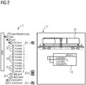
- a user creates an Equipment Hierarchy (EQH) 7 by means of suitable software of an engineering system of the process control system not shown here (FIG. FIG. 2 ) representing a technological view of a technical facility to be controlled.
- EQH Equipment Hierarchy
- nodes 8, 9 are entered in a structured manner in accordance with a tree structure or deposited, of which the nodes 8 plant pictures, z. "HMITank1" and “HMIControl”, and nodes 9 represent CFC charts and process objects, such as monitor and controller objects ("monans_1", ..., "pidcons_1").
- the user also creates a picture hierarchy (display hierarchy) 10 (FIG. FIG. 3 ), in which also structured nodes 8 are registered or deposited, the plant images, z. For example, "HMI_Brent” and "HMI_MonAnS").
- the respective plant pictures can be online, d. H.
- the process control - be opened by an operator to process viewing each selected the respective plant image node 8 of the equipment hierarchy 7 or the image hierarchy 10 or by means of a "mouse" clicks, whereby the plant attached to the plant node associated image opens and on the operator client 5 is displayed.
- the present example shows a detail of a plant image 11 comprising a graphic image symbol 12 and a block icon 13 associated with a process object, the block icon 13 being for process observation and current process values, parameters and alarm flags 29 of this process object during process control displays.
- the operator z. B. this process object - for example, by changing the setpoint and / or other parameters - influence by selecting the corresponding node 9 for this process object in the equipment hierarchy 7 or "clicks".
- a faceplate (not shown here for process control) associated with this process object is opened and displayed on the operator client 5, this faceplate having corresponding fields for entering, changing and / or deleting parameters of the process object.
- process object means the respective facets of a process object is stored in the operator client 5, in a process image 14 of the operator server 2 and in the automation device 4.
- process image 14 of the operator server 2 of the operator system has a process image block 15 associated with this process object, the automation device 4 an automation block 16 belonging to this process object, and also a user interface 26 of the operator client 5 for this process object associated faceplate 17 and block icon 18 of a system image 27 on.
- the operator servers 2, 3 have a first component 19, which interacts with the user interface 26.
- This first component 19 is designed to determine the process objects existing in the process control system on all operator servers 2, 3 from configuration data that the engineering system transmits to the respective operator server 2.
- the operator servers 2, 3 are provided with a second component 20, which is designed to map all alarms of the respective process objects occurring during process control to an alarm tag 21 of the process image block 15 of the process image 14 belonging to the respective process object , These alarms indicate process faults and are transmitted to the respective operator server 2, 3 by means of the automation module or modules 16 of the automation device 4.
- the first component 19 makes a request to the second component 20 for which the process objects determined by the first component 19 have an application for the alarm tag 21, which is an operator access to these process objects or an operator action 1
- the first component 19 identifies these process objects in the equipment hierarchy 7 and / or in the picture hierarchy 10 by means of a suitable marker 24 (FIG. Figures 2 and 3 ).
- a logon for the alarm tag 21 is present when an operator opens a plant picture in which the block icon belonging to this process object is displayed or when an operator selects the faceplate for this process object opens to serve it. This automatically identifies which process objects operators are currently interacting with.
- the first component (19) is informed by means of the second component (20).
- the second component 20, which is designed to map all alarms of the respective process objects occurring during the process control to an alarm tag 21 of the process image block 15 of the process image 14 belonging to the respective process object, is further configured to be primarily an alarming process object assigned system image - Primary Screen 22 - to determine z. B. that this primary screen 22 associated plant picture 27 of the operator client 5 can be displayed.
- the primary screen 22 represents the plant image 27, for whose alarm the process object in the image hierarchy is alarming, whereby the connection between the process object and the plant image can be established.
- this information can be collected on each operator server 2, 3 and provided for each operator client 5.
Abstract
Description
- Die Erfindung betrifft ein Verfahren zur Erkennen und Anzeigen von Operator-Zugriffen auf Prozessobjekte im Rahmen einer Prozessführung und Prozessbeobachtung gemäß dem Oberbegriff des Anspruchs 1. Die Erfindung betrifft ferner ein Operator-System gemäß dem Oberbegriff des Anspruchs 4 zur Durchführung des Verfahrens.
- In der Prozessleittechnik sind gewöhnlich hunderte von Anlagenbildern und mehrere tausend Prozessobjekte zu bearbeiten, wobei ein Prozessobjekt mehrere zusammengehörige Facetten aufweist. Beispielsweise umfasst ein Prozessabbild eines Servers eines Operator-Systems zu diesen Prozessobjekten gehörige Prozessabbild-Bausteine bzw. bedien- und beobachtungsrelevante Prozessdaten dieser Prozessobjekte, ein Automatisierungsgerät zu den Prozessobjekten gehörige Automatisierungs-bausteine bzw. Steuerbausteine (CFCs, SFCs, ...) und ferner ein User-Interface eines Clients des Operator-Systems zu den Prozessobjekten gehörige Blocksymbole eines Anlagenbildes sowie so genannte Faceplates, wobei die Anlagenbilder zur Prozessbeobachtung und die Faceplates zur Prozessführung bzw. Prozessbedienung vorgesehen sind.
- Die Prozessobjekte einer zu steuernden technischen Anlage, z. B. Prozessobjekte in Form von Messstellen, Tanks, Ventile, Sensoren, Aktuatoren, ..., sowie so genannte Continuous Function Charts (CFCs) und
Sequential Function Charts (SFCs) werden gewöhnlich in einer so genannten Equipment-Hierarchie (EQH) strukturiert, wobei ein Anwender diese Equipment-Hierarchie zunächst mittels einer geeigneten Software eines Engineering-Systems erstellt. Anschließend wird die derart erstellte Equipment-Hierarchie mittels des Engineering-Systems kompiliert und in Operator-Server von Operator-Systemen eines Prozessleitsystems geladen (Compile & Download), wobei zur Laufzeit der Operator-Systeme bzw. des Prozessleitsystems die Equipment-Hierarchie als zentrale Anlaufstelle z. B. für einen Batchprozess oder zur Navigation bzw. zur Ermittlung eines Prozessobjektes innerhalb der Equipment-Hierarchie genutzt wird. Die Equipment-Hierarchie weist neben ersten Knoten, die Anlagenbilder repräsentieren, auch zweite Knoten auf, welche die Prozessobjekte repräsentieren. Ein Operator kann einerseits durch Selektion bzw. durch Anklicken eines Anlagenbild-Knotens das entsprechende Anlagenbild zur Darstellung auf einer Anzeigeeinheit öffnen, und anderseits durch Selektion bzw. durch Anklicken eines Prozessobjekt-Knotens ein diesem Prozessobjekt zugehöriges Faceplate öffnen, wodurch der Operator das Prozessobjekt bedienen kann. - Auch mit einer weiteren, einer so genannten Bildhierarchie ist es möglich, im Rahmen einer Prozessbedienung und Prozessbeobachtung in verfahrenstechnischen Anlagen zu navigieren. Jedes Anlagenbild wird in der Bildhierarchie als Knoten hierarchisch repräsentiert und durch Selektion bzw. Anklicken dieses Knotens wird das Anlagenbild geöffnet und auf dem Operator-Client dargestellt, wobei ein derartiges Anlagenbild grafische Bildsymbole sowie Blocksymbole der Prozessobjekte umfasst.
- Um insbesondere bei Prozessstörungen das Navigieren zu erleichtern, können die Hierarchien durch Alarmstatusinformation "dynamisiert" werden, was bedeutet, dass Alarme, die auf die Störungen im Prozess hinweisen, den Operatoren angezeigt werden, indem z. B. in einem Anlagenbild ein Block-Symbol eines Prozessobjekts, welches einen Alarm meldet, auch in der Equipment- und/oder Bildhierarchie am entsprechenden Knoten durch ein Alarmsymbol dargestellt wird. Dadurch kann ein Operator gezielt die Anlagenbilder öffnen, die "alarmgebende" Block-Symbole von Prozessobjekten aufweisen, oder gezielt die entsprechende Prozessobjekt-Knoten öffnen, um entsprechende Prozessbedienungen bewerkstelligen zu können.
- Aufgrund dessen, dass in einem Prozessleitsystem gewöhnlich hunderte von Anlagenbildern und tausende von Prozessobjekten vorhanden sind, sind die Bildhierarchie und die Equipment-Hierarchie sehr umfangreich. Darüber hinaus sind zum Betrieb der Anlage zahlreiche Operatoren gleichzeitig - oft auch räumlich in verschiedenen Leitwarten getrennt - im Einsatz. Dadurch ist es für die Operatoren sehr schwierig, sich zu koordinieren, insbesondere in Ausnahmesituationen, wenn quasi gleichzeitig sehr viele Alarme auftreten und bearbeitet werden müssen, um die Anlage wieder in einen sicheren Zustand fahren zu können. Gewöhnlich wird eine Koordination der Zugriffe bzw. der Bearbeitungen über gängige Kommunikationsmittel (E-Mail, Telefon, ...) bewerkstelligt. Um eine Anlage in einer solchen Ausnahmesituation wieder effizient, sicher und schnell in den Regelbetrieb überführen zu können, ist eine derartige Koordination oft fehlerbehaftet und wenig effizient.
- Der Erfindung liegt daher die Aufgabe zugrunde, ein Verfahren der eingangs genannten Art anzugeben, mittels dessen eine effiziente Koordination von Operator-Zugriffen ermöglicht wird. Darüber hinaus ist ein Operator-System gemäß dem Oberbegriff des Anspruchs 4 zu schaffen, welches zur Durchführung des Verfahrens geeignet ist.
- Diese Aufgabe wird im Hinblick auf das Verfahren durch die im kennzeichnenden Teil des Anspruchs 1 angegebenen, bezüglich des Operator-Systems durch die im kennzeichnenden Teil des Anspruchs 4 angegebenen Maßnahmen gelöst.
- Vorteilhaft ist, dass die Bedienungen bzw. Handlungen von Operatoren automatisch erkannt, zugeordnet und visualisiert werden, wodurch eine optimierte und automatisch geführte Koordination der Operatoren ermöglicht wird um effizient und schnell die Anlage in einem sicheren Zustand führen zu können. Absprachen der Operatoren untereinander über Kommunikationsmittel sind nicht erforderlich. Ferner werden Mehrfachbedienungen zu Lasten der Bearbeitung von noch anstehenden Prozessalarmen vermieden, wodurch eine effiziente Behandlung von verfahrenstechnischen Anlagen in Ausnahmesituationen ermöglicht wird.
- Weitere vorteilhafte Ausgestaltungen der Erfindung ergeben sich aus den Unteransprüchen.
- Anhand der Zeichnung, in der ein Ausführungsbeispiel der Erfindung veranschaulicht ist, werden im Folgenden die Erfindung, deren Ausgestaltungen sowie Vorteile näher erläutert.
- Es zeigen in einer vereinfachten Form:
-
Figur 1 Bestandteile eines Leitsystems, -
Figur 2 eine Equipment-Hierarchie und ein Anlagenbild und -
Figur 3 eine Bildhierarchie und ein Anlagenbild. - Die in den
Figuren 1 bis 3 dargestellten gleichen Teile sind mit gleichen Bezugszeichen versehen. - In
Figur 1 sind mit 1 Bestandteile eines Prozessleitsystems bezeichnet, die im vorliegenden Ausführungsbeispiel Operator-Server 2, 3 sowie ein Automatisierungsgerät 4 und einen Operator-Client 5 umfassen. Das Prozessleitsystem kann selbstverständlich eine Vielzahl von Automatisierungsgeräten aufweisen, die einerseits über einen Plant Bus 6 mit den Operator-Servern 2, 3 und andererseits über einen weiteren hier nicht dargestellten Bus mit dezentralen Peripherien verbunden sind, an welche eine Vielzahl von Feldgeräten (Sensoren, Aktuatoren) angeschlossen sind. Im vorliegenden Beispiel ist lediglich ein Operator-Client 5 dargestellt. Selbstverständlich können weitere OS-Clients vorgesehen sein, wobei gewöhnlich jeweils ein Operator-Server und ein Operator-Client ein Operator-System bzw. eine Operator-Station bilden. - Ein Anwender erstellt mittels einer geeigneten Software eines hier nicht dargestellten Engineering-Systems des Prozessleitsystems eine Equipment-Hierarchie (EQH) 7 (
Figur 2 ), welche eine technologische Sicht einer zu steuernden technischen Anlage repräsentiert. In dieser Equipment-Hierarchie 7 sind strukturiert gemäß einer Baumstruktur Knoten 8, 9 eingetragen bzw. hinterlegt, von denen die Knoten 8 Anlagenbilder, z. B. "HMITank1" und "HMIControl", und die Knoten 9 CFC-Pläne und Prozessobjekte, beispielsweise Überwachungs- und Reglerobjekte ("monans_1", ..., "pidcons_1"), repräsentieren. - Mittels der genannten oder einer weiteren geeigneten Software des Engineering-Systems erstellt der Anwender ferner eine Bildhierarchie (Display Hierarchy) 10 (
Figur 3 ), in welcher ebenfalls strukturiert Knoten 8 eingetragen bzw. hinterlegt sind, die Anlagenbilder, z. B. "HMI_Brent" und "HMI_MonAnS") repräsentieren. - Die jeweiligen Anlagenbilder können online, d. h. während der Prozesssteuerung - geöffnet werden, indem zur Prozessbeobachtung ein Operator jeweils den entsprechenden Anlagenbild-Knoten 8 der Equipment-Hierarchie 7 oder der Bildhierarchie 10 selektiert bzw. mittels einer "Maus" anklickt, wodurch das dem selektierten Anlagen-Knoten zugehörige Anlagenbild geöffnet und auf dem Operator-Client 5 dargestellt wird. Das vorliegende Beispiel zeigt einen Ausschnitt eines Anlagenbildes 11, das ein grafisches Bildsymbol 12 und ein zu einem Prozessobjekt gehöriges Block-Symbol 13 umfasst, wobei das Block-Symbol 13 zur Prozessbeobachtung vorgesehen ist und aktuelle Prozesswerte, Parameter und Alarmkennzeichnungen 29 dieses Prozessobjektes während der Prozesssteuerung anzeigt.
- Im Hinblick auf eine Prozessführung kann der Operator z. B. dieses Prozessobjekt - beispielsweise durch Ändern des Sollwerts und/oder weiteren Parameter - beeinflussen, indem er den entsprechenden Knoten 9 für dieses Prozessobjekt in der Equipment-Hierarchie 7 selektiert bzw. "anklickt". Dadurch wird ein zu diesem Prozessobjekt gehöriges hier nicht dargestelltes zur Prozessführung vorgesehenes Faceplate geöffnet und auf dem Operator-Client 5 dargestellt, wobei dieses Faceplate entsprechende Felder zum Eingeben, Ändern und/oder Löschen von Parametern des Prozessobjektes aufweist.
- Es wird darauf hingewiesen, dass unter dem Begriff "Prozessobjekt" die jeweiligen Facetten eines Prozessobjektes verstanden wird, die im Operator-Client 5, in einem Prozessabbild 14 des Operator-Servers 2 und im Automatisierungsgerät 4 hinterlegt sind. So weist das Prozessabbild 14 des Operator-Servers 2 des Operator-Systems einen zu diesem Prozessobjekt gehörigen Prozessabbild-Baustein 15, das Automatisierungsgerät 4 ein zu diesem Prozessobjekt gehörigen Automatisierungsbaustein 16 und ferner ein User-Interface 26 des Operator-Clients 5 ein zu diesem Prozessobjekt gehöriges Faceplate 17 und Blocksymbol 18 eines Anlagenbildes 27 auf.
- Um eine effiziente Koordination von Operator-Zugriffen zu ermöglichen, weisen die Operator-Server 2,3 eine erste Komponente 19 auf, die mit dem User-Interface 26 zusammenwirkt. Diese erste Komponente 19 ist dazu ausgebildet, die im Prozessleitsystem auf allen Operator-Servern 2, 3 vorhandenen Prozessobjekte aus Projektierungsdaten zu ermitteln, die das Engineering-System dem jeweiligen Operator-Server 2 übermittelt. Ferner sind die Operator-Server 2, 3 mit einer zweiten Komponente 20 versehen, die dazu ausgebildet ist, alle während der Prozesssteuerung auftretende Alarme der jeweiligen Prozessobjekte auf einen Alarm-Tag 21 des zu dem jeweiligen Prozessobjekt gehörigen Prozessabbild-Bausteins 15 des Prozessabbildes 14 abzubilden. Diese Alarme weisen auf Prozessstörungen hin und werden mittels des oder der Automatisierungs-Bausteine 16 des Automatisierungsgerätes 4 dem jeweiligen Operator-Server 2, 3 übermittelt.
- Für den Fall, dass die erste Komponente 19 eine Anfrage an die zweite Komponente 20 stellt, für welche der von der ersten Komponente 19 ermittelten Prozessobjekte eine Anmeldung für den Alarm-Tag 21 vorliegt, was auf einen Operatorzugriff auf diese Prozessobjekte bzw. auf eine Operatorhandlung hinweist, kennzeichnet die erste Komponente 19 diese Prozessobjekte in der Equipment-Hierarchie 7 und/oder in der Bildhierarchie 10 mittels einer geeigneten Markierung 24 (
Figuren 2 und3 ). Eine Anmeldung für den Alarm-Tag 21 liegt dann vor, wenn ein Operator ein Anlagenbild öffnet, in dem das zu diesem Prozessobjekt gehörige Block-Symbol eingeblendet wird oder wenn ein Operator das Faceplate für dieses Prozessobjekt öffnet, um es zu bedienen. Dadurch wird automatisch erkannt, mit welchen Prozessobjekten Operatoren gerade interagieren. Über Änderungen am Alarm-Tag 21 wird mittels der zweiten Komponente (20) die erste Komponente (19) informiert. - Die zweite Komponente 20, die dazu ausgebildet ist, alle während der Prozesssteuerung auftretende Alarme der jeweiligen Prozessobjekte auf einen Alarm-Tag 21 des zu dem jeweiligen Prozessobjekt gehörigen Prozessabbild-Bausteins 15 des Prozessabbildes 14 abzubilden, ist ferner dazu ausgebildet, das primär einem alarmgebenden Prozessobjekt zugeordnete Anlagenbild - Primary Screen 22 - zu ermitteln, wobei z. B. das diesem Primary Screen 22 zugehörige Anlagenbild 27 des Operator-Clients 5 darstellbar ist. Der Primary Screen 22 repräsentiert das Anlagenbild 27, für dessen Alarm das Prozessobjekt in der Bildhierarchie alarmgebend ist, wodurch die Verbindung zwischen Prozessobjekt und Anlagenbild hergestellt werden kann. Mittels einer weiteren Komponente 28 kann diese Information auf jedem Operator-Server 2, 3 gesammelt und für jeden Operator-Client 5 bereitgestellt werden.
- Im Folgenden wird auf die
Figuren 2 und3 verwiesen, in welchen zur Laufzeit bzw. während der Prozesssteuerung durch die Markierungen 24 gekennzeichnet ist, auf welche Prozessobjekte die Operatoren gerade zugreifen, wobei z. B. ein markiertes Prozessobjekt "pidcons_1" in der Equipment-Hierarchie 7 auch als Blocksymbol 13 im Anlagenbild 11 dargestellt ist (Figur 2 ). - Aufgrund der Darstellung der Operatorenhandlungen wird eine optimierte Koordination der Bedienung und Beobachtung in der Bildhierarchie 10 und/oder Equipment-Hierarchie 7 zur Laufzeit ermöglicht. Im vorliegenden Beispiel, in welchem Alarme mit 23 (
Figur 3 ) bezeichnet sind, hat ein Operator gerade das Anlagenbild "HMITank1" geöffnet, was in derFigur 3 mittels einer Schraffur 25 dargestellt ist, um das darin alarmgebende Prozessobjekt zu bedienen. Dieser Operator kann unmittelbar an der angezeigten Markierung 24 in der Bildhierarchie 10 erkennen, dass ein anderer Operator gerade einen Alarm im Anlagenbild "HMI_MonAnS" bearbeitet und ferner noch kein Operator den Alarm 23 im Anlagenbild "HMI_PlantSection1" bearbeitet. Ohne Absprachen der Operatoren untereinander können die Operatoren erkennen, welche alarmgebenden Prozessobjekte noch zu bearbeiten sind, wobei Maßnahmen vorgesehen werden können, gerade nicht an einer Prozessführung beteiligte Operatoren an die Stellen in der Bildhierarchie 10 zu führen, an denen Bedienungen zur Alarmbearbeitung bzw. Alarmbehebung erforderlich sind.
Claims (6)
- Verfahren zum Erkennen und Anzeigen von Operator-Zugriffen auf Prozessobjekte im Rahmen einer Prozessführung und Prozessbeobachtung, wobei- zumindest ein Operator-Server (2, 3) eines Prozessleitsystems ein Prozessabbild (14) aufweist, das versehen ist mit zu Prozessobjekten gehörigen Prozessabbild-Bausteinen (15),- zumindest ein Automatisierungsgerät (4) versehen ist mit zu den Prozessobjekten gehörige Automatisierungs-Bausteinen (16),- zur Prozessbeobachtung ein User-Interface (26) versehen ist mit zu den Prozessobjekten gehörigen Block-Symbolen (13, 18) von Anlagenbildern (11),- zur Prozessführung das User-Interface (26) versehen ist mit zu den Prozessobjekten gehörigen Faceplates (17),- zum Öffnen von Anlagenbildern (11) zur Darstellung auf einer Anzeige für das jeweilige Anlagenbild ein durch einen Anwender selektierbarer Knoten (8, 9) in einer Bildhierarchie (10) und/oder in einer Equipment-Hierarchie (7) hinterlegt ist, wobei das Anlagenbild (11) grafische Bild-Symbole (12) und die zu den Prozessobjekten gehörigen Block-Symbole (13) umfasst,dadurch gekennzeichnet, dass- mittels einer ersten Komponente (19) des Operator-Servers (2, 3) die Prozessobjekte aus Projektierungsdaten eines Engineering-Systems des Prozessleitsystems ermittelt werden,- mittels einer zweiten Komponente (20) des Operator-Servers (2) Alarme der jeweiligen Prozessobjekte auf einen Alarm-Tag (21) des zu dem jeweiligen Prozessobjekt gehörigen Prozessabbild-Bausteins (15) abgebildet werden, wobei die Alarme auf Prozessstörungen hinweisen und diese mittels der Automatisierungs-Bausteine (16) des Automatisierungsgerätes (4) dem Operator-Server übermittelt werden,- die Knoten (8, 9) in der Bildhierarchie und/oder der Equipment-Hierarchie markiert werden, die ein alarmgebendes Prozessobjekt umfassen, wobei für den Fall, dass ein Operator einen derartigen Knoten (8, 9) selektiert, dieser Knoten (8, 9) mit einer weiteren Kennzeichnung (24) markiert wird.
- Verfahren nach Anspruch 1, dadurch gekennzeichnet, dass mittels der zweiten Komponente (20) die erste Komponente (19) über Änderungen des Alarm-Tags (21) informiert wird.
- Verfahren nach Anspruch 1 oder 2, dadurch gekennzeichnet, dass mittels der zweiten Komponente (20) das primär dem Prozessobjekt zugeordnete Anlagenbild ermittelt wird.
- Operator-System für ein Prozessleitsystem, wobei- ein Operator-Server (2, 3) des Operator-Systems ein Prozessabbild (14) aufweist, das versehen ist mit zu Prozessobjekten gehörigen Prozessabbild-Bausteinen (15),- zur Prozessbeobachtung ein User-Interface (26) eines Operator-Clients (5) des Operator-Systems versehen ist mit zu den Prozessobjekten gehörigen Block-Symbolen (13) von Anlagenbildern (11),- zur Prozessführung das User-Interface (26) versehen ist mit zu den Prozessobjekten gehörigen Faceplates (17),- zum Öffnen von Anlagenbildern zur Darstellung auf einer Anzeige des Operator-Clients (5) für das jeweilige Anlagenbild ein durch einen Anwender selektierbarer Knoten (8, 9) in einer Bildhierarchie (10) und/oder in einer Equipment-Hierarchie (7) hinterlegt ist, wobei das Anlagenbild (11) grafische Bild-Symbole (12) und die zu den Prozessobjekten gehörigen Block-Symbole (13) umfasst,dadurch gekennzeichnet, dass- eine erste Komponente (19) des Operator-Servers (2, 3) dazu ausgebildet ist, die Prozessobjekte aus Projektierungsdaten eines Engineering-Systems des Prozessleitsystems zu ermitteln,- eine zweite Komponente (20) des Operator-Servers (2, 3) dazu ausgebildet ist, Alarme der jeweiligen Prozessobjekte auf einen Alarm-Tag (21) des zu dem jeweiligen Prozessobjekt gehörigen Prozessabbild-Bausteins (15) abzubilden, wobei die Alarme auf Prozessstörungen hinweisen, die zu den Prozessobjekten gehörige Automatisierungs-Bausteine (16) eines Automatisierungsgerätes (4) dem Operator-Server (2, 3) übermittelt,- die erste Komponente (19) dazu ausgebildet ist, die Knoten (8, 9) in der Bildhierarchie (10) und/oder der Equipment-Hierarchie (7) zu markieren, die ein alarmgebendes Prozessobjekt umfassen, wobei für den Fall, dass ein Operator einen derartigen Knoten (8, 9) selektiert, die erste Komponente (19) diesen Knoten (8, 9) mit einer weiteren Markierung (24) kennzeichnet.
- Operator-System nach Anspruch 4, dadurch gekennzeichnet, dass die zweiten Komponente (20) dazu ausgebildet ist, die erste Komponente (19) über Änderungen des Alarm-Tags (21) zu informieren.
- Operator-System nach Anspruch 4 oder 5, dadurch gekennzeichnet, dass die zweite Komponente (20) ferner dazu ausgebildet ist, das primär dem Prozessobjekt zugeordnete Anlagenbild zu ermitteln.
Priority Applications (5)
| Application Number | Priority Date | Filing Date | Title |
|---|---|---|---|
| EP17200152.1A EP3480672B1 (de) | 2017-11-06 | 2017-11-06 | Verfahren zum erkennen und anzeigen von operator-zugriffen auf prozessobjekte sowie operator-system |
| BR102018067904A BR102018067904B8 (pt) | 2017-11-06 | 2018-09-05 | Método para identificar e exibir acessos de operador a objetos de processo, e, sistema de operador |
| CN201811072905.4A CN109753029B (zh) | 2017-11-06 | 2018-09-14 | 识别和显示操作员访问过程对象的方法及操作员系统 |
| RU2018137672A RU2716743C1 (ru) | 2017-11-06 | 2018-10-25 | Способ распознавания и отображения доступов оператора к объектам процесса, а также операторская система |
| US16/180,740 US10452044B2 (en) | 2017-11-06 | 2018-11-05 | Operating system and method for identifying and displaying operator accesses to process objects and operator system |
Applications Claiming Priority (1)
| Application Number | Priority Date | Filing Date | Title |
|---|---|---|---|
| EP17200152.1A EP3480672B1 (de) | 2017-11-06 | 2017-11-06 | Verfahren zum erkennen und anzeigen von operator-zugriffen auf prozessobjekte sowie operator-system |
Publications (2)
| Publication Number | Publication Date |
|---|---|
| EP3480672A1 true EP3480672A1 (de) | 2019-05-08 |
| EP3480672B1 EP3480672B1 (de) | 2020-02-19 |
Family
ID=60301785
Family Applications (1)
| Application Number | Title | Priority Date | Filing Date |
|---|---|---|---|
| EP17200152.1A Active EP3480672B1 (de) | 2017-11-06 | 2017-11-06 | Verfahren zum erkennen und anzeigen von operator-zugriffen auf prozessobjekte sowie operator-system |
Country Status (5)
| Country | Link |
|---|---|
| US (1) | US10452044B2 (de) |
| EP (1) | EP3480672B1 (de) |
| CN (1) | CN109753029B (de) |
| BR (1) | BR102018067904B8 (de) |
| RU (1) | RU2716743C1 (de) |
Cited By (4)
| Publication number | Priority date | Publication date | Assignee | Title |
|---|---|---|---|---|
| EP3968107A1 (de) * | 2020-09-09 | 2022-03-16 | Siemens Aktiengesellschaft | Prozessüberwachungssystem und verfahren zum betrieb eines prozessüberwachungssystems |
| EP4095634A1 (de) | 2021-05-26 | 2022-11-30 | Siemens Aktiengesellschaft | Leitsystem für eine technische anlage |
| EP4099114A1 (de) * | 2021-05-31 | 2022-12-07 | Siemens Aktiengesellschaft | Verfahren zum erkennen einer eingeschränkten bedienung und beobachtung einer technischen anlage, bedien- und beobachtungssystem und prozessleitsystem |
| EP4336293A1 (de) | 2022-09-08 | 2024-03-13 | Siemens Aktiengesellschaft | Verfahren zum warnen eines benutzers einer operator station, computerprogrammprodukt, steuereinheit und automatisierungsanlage |
Families Citing this family (1)
| Publication number | Priority date | Publication date | Assignee | Title |
|---|---|---|---|---|
| EP3796119A1 (de) * | 2019-09-23 | 2021-03-24 | Siemens Aktiengesellschaft | Erweiterte trendanzeige von prozessdaten und sekundäralarmen |
Citations (3)
| Publication number | Priority date | Publication date | Assignee | Title |
|---|---|---|---|---|
| US7457675B2 (en) * | 2005-08-15 | 2008-11-25 | Abb Inc. | External status asset monitor |
| EP2149825A1 (de) * | 2008-07-31 | 2010-02-03 | Siemens Aktiengesellschaft | Projektnavigator zur hierarchischen Darstellung von Technologieobjekten, Verwendung eines derartigen Projektnavigators, Speichermedium und Engineering-System |
| US20130021355A1 (en) * | 2010-04-14 | 2013-01-24 | Yokogawa Electric Corporation | Method and system for displaying proiritized live thumbnail of process graphic views |
Family Cites Families (20)
| Publication number | Priority date | Publication date | Assignee | Title |
|---|---|---|---|---|
| US7017116B2 (en) * | 1999-01-06 | 2006-03-21 | Iconics, Inc. | Graphical human-machine interface on a portable device |
| US20020070972A1 (en) * | 2000-10-27 | 2002-06-13 | Helmut Windl | Industrial automation display arrangement and method |
| US20090271504A1 (en) * | 2003-06-09 | 2009-10-29 | Andrew Francis Ginter | Techniques for agent configuration |
| US7246156B2 (en) * | 2003-06-09 | 2007-07-17 | Industrial Defender, Inc. | Method and computer program product for monitoring an industrial network |
| JP2007536634A (ja) * | 2004-05-04 | 2007-12-13 | フィッシャー−ローズマウント・システムズ・インコーポレーテッド | プロセス制御システムのためのサービス指向型アーキテクチャ |
| CN100550762C (zh) * | 2004-08-08 | 2009-10-14 | 华为技术有限公司 | 一种对通知日志进行操作的实现方法 |
| DE102006014634B4 (de) * | 2005-04-01 | 2014-01-30 | Abb Research Ltd. | Mensch-Maschine-Schnittstelle für ein Kontroll- bzw. Steuerungs-System |
| CN100556037C (zh) * | 2005-07-08 | 2009-10-28 | 中兴通讯股份有限公司 | 一种snmp协议下采用确认机制实现告警管理的方法 |
| US20070239291A1 (en) * | 2006-04-11 | 2007-10-11 | Invensys Systems, Inc. | Runtime human-machine interface for process control having enhanced view hierarchy navigation controls |
| US9244455B2 (en) * | 2007-09-10 | 2016-01-26 | Fisher-Rosemount Systems, Inc. | Location dependent control access in a process control system |
| RU90588U1 (ru) * | 2008-11-14 | 2010-01-10 | Евгений Сергеевич Самарцев | Аппаратно-программный комплекс автоматизации, управления, визуализации и мониторинга технологических процессов |
| EP2422249B1 (de) * | 2009-04-20 | 2013-03-27 | ABB Research Ltd. | Bedienerendgerät in einem prozesssteuersystem |
| US8423305B2 (en) * | 2009-12-23 | 2013-04-16 | The Boeing Company | Wire system assessment |
| DE112014001472T5 (de) * | 2013-03-15 | 2015-12-17 | Fisher-Rosemount Systems, Inc. | Grafische Trendüberwachung von Prozessvariablen für ein Prozesssteuerungssystem |
| US9722801B2 (en) * | 2013-09-30 | 2017-08-01 | Juniper Networks, Inc. | Detecting and preventing man-in-the-middle attacks on an encrypted connection |
| US9547291B2 (en) * | 2013-10-14 | 2017-01-17 | Ivensys Systems, Inc. | Human machine interface (HMI) system having a symbol wizard creator |
| CN103676896B (zh) * | 2013-12-20 | 2016-08-17 | 中广核核电运营有限公司 | 核电厂数字化控制室人机界面改进方法 |
| EP3067768B1 (de) * | 2015-03-11 | 2018-04-25 | Siemens Aktiengesellschaft | Automatisierungseinrichtung und Operator-System |
| JP7044452B2 (ja) * | 2015-10-12 | 2022-03-30 | フィッシャー-ローズマウント システムズ,インコーポレイテッド | プロセス制御システムにおけるグラフィカルなプロセス変数トレンドの監視、予測解析、及び故障の検出 |
| US10657776B2 (en) * | 2016-10-24 | 2020-05-19 | Fisher-Rosemount Systems, Inc. | Alarm handling and viewing support in a process plant |
-
2017
- 2017-11-06 EP EP17200152.1A patent/EP3480672B1/de active Active
-
2018
- 2018-09-05 BR BR102018067904A patent/BR102018067904B8/pt active Search and Examination
- 2018-09-14 CN CN201811072905.4A patent/CN109753029B/zh active Active
- 2018-10-25 RU RU2018137672A patent/RU2716743C1/ru active
- 2018-11-05 US US16/180,740 patent/US10452044B2/en active Active
Patent Citations (3)
| Publication number | Priority date | Publication date | Assignee | Title |
|---|---|---|---|---|
| US7457675B2 (en) * | 2005-08-15 | 2008-11-25 | Abb Inc. | External status asset monitor |
| EP2149825A1 (de) * | 2008-07-31 | 2010-02-03 | Siemens Aktiengesellschaft | Projektnavigator zur hierarchischen Darstellung von Technologieobjekten, Verwendung eines derartigen Projektnavigators, Speichermedium und Engineering-System |
| US20130021355A1 (en) * | 2010-04-14 | 2013-01-24 | Yokogawa Electric Corporation | Method and system for displaying proiritized live thumbnail of process graphic views |
Cited By (6)
| Publication number | Priority date | Publication date | Assignee | Title |
|---|---|---|---|---|
| EP3968107A1 (de) * | 2020-09-09 | 2022-03-16 | Siemens Aktiengesellschaft | Prozessüberwachungssystem und verfahren zum betrieb eines prozessüberwachungssystems |
| EP4095634A1 (de) | 2021-05-26 | 2022-11-30 | Siemens Aktiengesellschaft | Leitsystem für eine technische anlage |
| WO2022248422A1 (de) | 2021-05-26 | 2022-12-01 | Siemens Aktiengesellschaft | Leitsystem für eine technische anlage |
| EP4099114A1 (de) * | 2021-05-31 | 2022-12-07 | Siemens Aktiengesellschaft | Verfahren zum erkennen einer eingeschränkten bedienung und beobachtung einer technischen anlage, bedien- und beobachtungssystem und prozessleitsystem |
| US11860611B2 (en) | 2021-05-31 | 2024-01-02 | Siemens Aktiengesellschaft | Method for identifying a limited operator control and monitoring of a technical plant, operator control and monitoring system and process control system |
| EP4336293A1 (de) | 2022-09-08 | 2024-03-13 | Siemens Aktiengesellschaft | Verfahren zum warnen eines benutzers einer operator station, computerprogrammprodukt, steuereinheit und automatisierungsanlage |
Also Published As
| Publication number | Publication date |
|---|---|
| EP3480672B1 (de) | 2020-02-19 |
| BR102018067904A2 (pt) | 2019-06-04 |
| US20190137962A1 (en) | 2019-05-09 |
| CN109753029A (zh) | 2019-05-14 |
| RU2716743C1 (ru) | 2020-03-16 |
| US10452044B2 (en) | 2019-10-22 |
| BR102018067904B8 (pt) | 2022-01-18 |
| BR102018067904B1 (pt) | 2021-12-07 |
| CN109753029B (zh) | 2022-01-11 |
Similar Documents
| Publication | Publication Date | Title |
|---|---|---|
| EP3480672B1 (de) | Verfahren zum erkennen und anzeigen von operator-zugriffen auf prozessobjekte sowie operator-system | |
| EP1330685B1 (de) | Prüfverfahren und prüfvorrichtung zur inbetriebnahme von mittels einer programmlogik gesteuerten systemen | |
| EP3495903B1 (de) | Verfahren zum bedienen und beobachten einer zu steuernden technischen anlage sowie operator-system | |
| EP1110127B1 (de) | Informations-, bedien- und/oder beobachtungssystem mit modellbasierter benutzeroberfläche und verfahren zum modellbasierten bedienen und/oder beobachten | |
| EP0563684B1 (de) | Überwachungsverfahren und Beobachtungssystem für einen technischen Prozess | |
| DE10309246B4 (de) | Verfahren für das Event Management | |
| EP3528074B1 (de) | Verfahren zum überprüfen der beziehung zwischen einem visuell auf einem operator-client eines prozessleitsystems dargestellten und einem akustisch ausgegebenen prozessalarm eines prozessobjektes sowie operator-system | |
| DE102016123235B4 (de) | Betriebsverwaltungssystem zum direkten anzeigen eines arbeitsbefehls auf basis einer betriebsverwaltungsinformation an einer werkzeugmaschine | |
| EP2808749B1 (de) | Verfahren zum Austausch von Steuerungsinformationen zwischen Bedien- und Beobachtungsgeräten eines industriellen Automatisierungssystems und industrielles Automatisierungssystem | |
| DE102009021062A1 (de) | Alarmverwaltungssystem | |
| EP3598255B1 (de) | Anordnung mit operator-servern und mit operator-clients | |
| EP4099114A1 (de) | Verfahren zum erkennen einer eingeschränkten bedienung und beobachtung einer technischen anlage, bedien- und beobachtungssystem und prozessleitsystem | |
| EP1092210B1 (de) | Vorrichtung und verfahren zur erstellung eines virtuellen anlagenmodells | |
| EP3508928A1 (de) | Verfahren zum verarbeiten von alarmen in einem prozessleitsystem sowie operator-system | |
| EP3699704B1 (de) | System und verfahren zum überprüfen von systemanforderungen von cyber-physikalischen systemen | |
| DE102020119853B3 (de) | Verfahren zum Steuern eines Automatisierungssystems mit Visualisierung von Programmobjekten eines Steuerprogramms des Automatisierungssystems und Automatisierungssystem | |
| EP1950635A1 (de) | Verfahren zum Betrieb eines Automatisierungssystems | |
| EP2560085A1 (de) | Verfahren zur Konfiguration einer Anzeigevorrichtung zur Anzeige von dynamischen Alarmmeldungen eines Steuer- und Überwachungssystems einer technischen Automatisierungsanlage | |
| EP1561172B1 (de) | Vorrichtung zur bereitstellung eines zugriffs auf daten | |
| EP3285162A1 (de) | Verfahren zum projektieren eines projektes sowie anordnung zur durchführung des verfahrens | |
| EP1655663A1 (de) | Datenflussmodellierung in Engineering-Systemen | |
| WO2014111257A1 (de) | Vorrichtung, system und verfahren zur maschinenwartung | |
| EP3617825A1 (de) | Automatisierte evaluierung von alarmhäufungen | |
| EP1636960B1 (de) | Automatisierungssystem mit vereinfachter diagnose und fehlerbehebung | |
| WO2018114184A1 (de) | Verfahren und bedieneinheit zur fehlerbehebung in einer anlage der automatisierungstechnik |
Legal Events
| Date | Code | Title | Description |
|---|---|---|---|
| PUAI | Public reference made under article 153(3) epc to a published international application that has entered the european phase |
Free format text: ORIGINAL CODE: 0009012 |
|
| STAA | Information on the status of an ep patent application or granted ep patent |
Free format text: STATUS: REQUEST FOR EXAMINATION WAS MADE |
|
| 17P | Request for examination filed |
Effective date: 20180619 |
|
| AK | Designated contracting states |
Kind code of ref document: A1 Designated state(s): AL AT BE BG CH CY CZ DE DK EE ES FI FR GB GR HR HU IE IS IT LI LT LU LV MC MK MT NL NO PL PT RO RS SE SI SK SM TR |
|
| AX | Request for extension of the european patent |
Extension state: BA ME |
|
| GRAP | Despatch of communication of intention to grant a patent |
Free format text: ORIGINAL CODE: EPIDOSNIGR1 |
|
| STAA | Information on the status of an ep patent application or granted ep patent |
Free format text: STATUS: GRANT OF PATENT IS INTENDED |
|
| INTG | Intention to grant announced |
Effective date: 20191118 |
|
| GRAS | Grant fee paid |
Free format text: ORIGINAL CODE: EPIDOSNIGR3 |
|
| GRAA | (expected) grant |
Free format text: ORIGINAL CODE: 0009210 |
|
| STAA | Information on the status of an ep patent application or granted ep patent |
Free format text: STATUS: THE PATENT HAS BEEN GRANTED |
|
| AK | Designated contracting states |
Kind code of ref document: B1 Designated state(s): AL AT BE BG CH CY CZ DE DK EE ES FI FR GB GR HR HU IE IS IT LI LT LU LV MC MK MT NL NO PL PT RO RS SE SI SK SM TR |
|
| REG | Reference to a national code |
Ref country code: CH Ref legal event code: EP |
|
| REG | Reference to a national code |
Ref country code: DE Ref legal event code: R096 Ref document number: 502017003850 Country of ref document: DE |
|
| REG | Reference to a national code |
Ref country code: AT Ref legal event code: REF Ref document number: 1235671 Country of ref document: AT Kind code of ref document: T Effective date: 20200315 |
|
| REG | Reference to a national code |
Ref country code: IE Ref legal event code: FG4D Free format text: LANGUAGE OF EP DOCUMENT: GERMAN |
|
| REG | Reference to a national code |
Ref country code: NL Ref legal event code: MP Effective date: 20200219 |
|
| PG25 | Lapsed in a contracting state [announced via postgrant information from national office to epo] |
Ref country code: RS Free format text: LAPSE BECAUSE OF FAILURE TO SUBMIT A TRANSLATION OF THE DESCRIPTION OR TO PAY THE FEE WITHIN THE PRESCRIBED TIME-LIMIT Effective date: 20200219 Ref country code: FI Free format text: LAPSE BECAUSE OF FAILURE TO SUBMIT A TRANSLATION OF THE DESCRIPTION OR TO PAY THE FEE WITHIN THE PRESCRIBED TIME-LIMIT Effective date: 20200219 Ref country code: NO Free format text: LAPSE BECAUSE OF FAILURE TO SUBMIT A TRANSLATION OF THE DESCRIPTION OR TO PAY THE FEE WITHIN THE PRESCRIBED TIME-LIMIT Effective date: 20200519 |
|
| REG | Reference to a national code |
Ref country code: LT Ref legal event code: MG4D |
|
| PG25 | Lapsed in a contracting state [announced via postgrant information from national office to epo] |
Ref country code: GR Free format text: LAPSE BECAUSE OF FAILURE TO SUBMIT A TRANSLATION OF THE DESCRIPTION OR TO PAY THE FEE WITHIN THE PRESCRIBED TIME-LIMIT Effective date: 20200520 Ref country code: HR Free format text: LAPSE BECAUSE OF FAILURE TO SUBMIT A TRANSLATION OF THE DESCRIPTION OR TO PAY THE FEE WITHIN THE PRESCRIBED TIME-LIMIT Effective date: 20200219 Ref country code: LV Free format text: LAPSE BECAUSE OF FAILURE TO SUBMIT A TRANSLATION OF THE DESCRIPTION OR TO PAY THE FEE WITHIN THE PRESCRIBED TIME-LIMIT Effective date: 20200219 Ref country code: SE Free format text: LAPSE BECAUSE OF FAILURE TO SUBMIT A TRANSLATION OF THE DESCRIPTION OR TO PAY THE FEE WITHIN THE PRESCRIBED TIME-LIMIT Effective date: 20200219 Ref country code: IS Free format text: LAPSE BECAUSE OF FAILURE TO SUBMIT A TRANSLATION OF THE DESCRIPTION OR TO PAY THE FEE WITHIN THE PRESCRIBED TIME-LIMIT Effective date: 20200619 Ref country code: BG Free format text: LAPSE BECAUSE OF FAILURE TO SUBMIT A TRANSLATION OF THE DESCRIPTION OR TO PAY THE FEE WITHIN THE PRESCRIBED TIME-LIMIT Effective date: 20200519 |
|
| PG25 | Lapsed in a contracting state [announced via postgrant information from national office to epo] |
Ref country code: NL Free format text: LAPSE BECAUSE OF FAILURE TO SUBMIT A TRANSLATION OF THE DESCRIPTION OR TO PAY THE FEE WITHIN THE PRESCRIBED TIME-LIMIT Effective date: 20200219 |
|
| PG25 | Lapsed in a contracting state [announced via postgrant information from national office to epo] |
Ref country code: PT Free format text: LAPSE BECAUSE OF FAILURE TO SUBMIT A TRANSLATION OF THE DESCRIPTION OR TO PAY THE FEE WITHIN THE PRESCRIBED TIME-LIMIT Effective date: 20200712 Ref country code: SK Free format text: LAPSE BECAUSE OF FAILURE TO SUBMIT A TRANSLATION OF THE DESCRIPTION OR TO PAY THE FEE WITHIN THE PRESCRIBED TIME-LIMIT Effective date: 20200219 Ref country code: RO Free format text: LAPSE BECAUSE OF FAILURE TO SUBMIT A TRANSLATION OF THE DESCRIPTION OR TO PAY THE FEE WITHIN THE PRESCRIBED TIME-LIMIT Effective date: 20200219 Ref country code: CZ Free format text: LAPSE BECAUSE OF FAILURE TO SUBMIT A TRANSLATION OF THE DESCRIPTION OR TO PAY THE FEE WITHIN THE PRESCRIBED TIME-LIMIT Effective date: 20200219 Ref country code: LT Free format text: LAPSE BECAUSE OF FAILURE TO SUBMIT A TRANSLATION OF THE DESCRIPTION OR TO PAY THE FEE WITHIN THE PRESCRIBED TIME-LIMIT Effective date: 20200219 Ref country code: ES Free format text: LAPSE BECAUSE OF FAILURE TO SUBMIT A TRANSLATION OF THE DESCRIPTION OR TO PAY THE FEE WITHIN THE PRESCRIBED TIME-LIMIT Effective date: 20200219 Ref country code: DK Free format text: LAPSE BECAUSE OF FAILURE TO SUBMIT A TRANSLATION OF THE DESCRIPTION OR TO PAY THE FEE WITHIN THE PRESCRIBED TIME-LIMIT Effective date: 20200219 Ref country code: SM Free format text: LAPSE BECAUSE OF FAILURE TO SUBMIT A TRANSLATION OF THE DESCRIPTION OR TO PAY THE FEE WITHIN THE PRESCRIBED TIME-LIMIT Effective date: 20200219 Ref country code: EE Free format text: LAPSE BECAUSE OF FAILURE TO SUBMIT A TRANSLATION OF THE DESCRIPTION OR TO PAY THE FEE WITHIN THE PRESCRIBED TIME-LIMIT Effective date: 20200219 |
|
| REG | Reference to a national code |
Ref country code: DE Ref legal event code: R097 Ref document number: 502017003850 Country of ref document: DE |
|
| PLBE | No opposition filed within time limit |
Free format text: ORIGINAL CODE: 0009261 |
|
| STAA | Information on the status of an ep patent application or granted ep patent |
Free format text: STATUS: NO OPPOSITION FILED WITHIN TIME LIMIT |
|
| 26N | No opposition filed |
Effective date: 20201120 |
|
| PG25 | Lapsed in a contracting state [announced via postgrant information from national office to epo] |
Ref country code: SI Free format text: LAPSE BECAUSE OF FAILURE TO SUBMIT A TRANSLATION OF THE DESCRIPTION OR TO PAY THE FEE WITHIN THE PRESCRIBED TIME-LIMIT Effective date: 20200219 Ref country code: PL Free format text: LAPSE BECAUSE OF FAILURE TO SUBMIT A TRANSLATION OF THE DESCRIPTION OR TO PAY THE FEE WITHIN THE PRESCRIBED TIME-LIMIT Effective date: 20200219 |
|
| REG | Reference to a national code |
Ref country code: CH Ref legal event code: NV Representative=s name: SIEMENS SCHWEIZ AG, CH |
|
| PG25 | Lapsed in a contracting state [announced via postgrant information from national office to epo] |
Ref country code: MC Free format text: LAPSE BECAUSE OF FAILURE TO SUBMIT A TRANSLATION OF THE DESCRIPTION OR TO PAY THE FEE WITHIN THE PRESCRIBED TIME-LIMIT Effective date: 20200219 |
|
| REG | Reference to a national code |
Ref country code: CH Ref legal event code: PL |
|
| PG25 | Lapsed in a contracting state [announced via postgrant information from national office to epo] |
Ref country code: LU Free format text: LAPSE BECAUSE OF NON-PAYMENT OF DUE FEES Effective date: 20201106 |
|
| REG | Reference to a national code |
Ref country code: BE Ref legal event code: MM Effective date: 20201130 |
|
| PG25 | Lapsed in a contracting state [announced via postgrant information from national office to epo] |
Ref country code: LI Free format text: LAPSE BECAUSE OF NON-PAYMENT OF DUE FEES Effective date: 20201130 Ref country code: CH Free format text: LAPSE BECAUSE OF NON-PAYMENT OF DUE FEES Effective date: 20201130 |
|
| PG25 | Lapsed in a contracting state [announced via postgrant information from national office to epo] |
Ref country code: IE Free format text: LAPSE BECAUSE OF NON-PAYMENT OF DUE FEES Effective date: 20201106 |
|
| PG25 | Lapsed in a contracting state [announced via postgrant information from national office to epo] |
Ref country code: TR Free format text: LAPSE BECAUSE OF FAILURE TO SUBMIT A TRANSLATION OF THE DESCRIPTION OR TO PAY THE FEE WITHIN THE PRESCRIBED TIME-LIMIT Effective date: 20200219 Ref country code: MT Free format text: LAPSE BECAUSE OF FAILURE TO SUBMIT A TRANSLATION OF THE DESCRIPTION OR TO PAY THE FEE WITHIN THE PRESCRIBED TIME-LIMIT Effective date: 20200219 Ref country code: CY Free format text: LAPSE BECAUSE OF FAILURE TO SUBMIT A TRANSLATION OF THE DESCRIPTION OR TO PAY THE FEE WITHIN THE PRESCRIBED TIME-LIMIT Effective date: 20200219 |
|
| PG25 | Lapsed in a contracting state [announced via postgrant information from national office to epo] |
Ref country code: MK Free format text: LAPSE BECAUSE OF FAILURE TO SUBMIT A TRANSLATION OF THE DESCRIPTION OR TO PAY THE FEE WITHIN THE PRESCRIBED TIME-LIMIT Effective date: 20200219 Ref country code: AL Free format text: LAPSE BECAUSE OF FAILURE TO SUBMIT A TRANSLATION OF THE DESCRIPTION OR TO PAY THE FEE WITHIN THE PRESCRIBED TIME-LIMIT Effective date: 20200219 |
|
| PG25 | Lapsed in a contracting state [announced via postgrant information from national office to epo] |
Ref country code: BE Free format text: LAPSE BECAUSE OF NON-PAYMENT OF DUE FEES Effective date: 20201130 |
|
| REG | Reference to a national code |
Ref country code: AT Ref legal event code: MM01 Ref document number: 1235671 Country of ref document: AT Kind code of ref document: T Effective date: 20221106 |
|
| PGFP | Annual fee paid to national office [announced via postgrant information from national office to epo] |
Ref country code: GB Payment date: 20231204 Year of fee payment: 7 |
|
| PG25 | Lapsed in a contracting state [announced via postgrant information from national office to epo] |
Ref country code: AT Free format text: LAPSE BECAUSE OF NON-PAYMENT OF DUE FEES Effective date: 20221106 |
|
| PGFP | Annual fee paid to national office [announced via postgrant information from national office to epo] |
Ref country code: IT Payment date: 20231122 Year of fee payment: 7 Ref country code: FR Payment date: 20231114 Year of fee payment: 7 |
|
| PGFP | Annual fee paid to national office [announced via postgrant information from national office to epo] |
Ref country code: DE Payment date: 20240119 Year of fee payment: 7 |