EP3480448A1 - Fan cowl with a serrated trailing edge providing attached flow in reverse thrust mode - Google Patents
Fan cowl with a serrated trailing edge providing attached flow in reverse thrust mode Download PDFInfo
- Publication number
- EP3480448A1 EP3480448A1 EP18203949.5A EP18203949A EP3480448A1 EP 3480448 A1 EP3480448 A1 EP 3480448A1 EP 18203949 A EP18203949 A EP 18203949A EP 3480448 A1 EP3480448 A1 EP 3480448A1
- Authority
- EP
- European Patent Office
- Prior art keywords
- ogvs
- fan cowl
- trailing edge
- periodic curves
- fan
- Prior art date
- Legal status (The legal status is an assumption and is not a legal conclusion. Google has not performed a legal analysis and makes no representation as to the accuracy of the status listed.)
- Pending
Links
Images


Classifications
-
- F—MECHANICAL ENGINEERING; LIGHTING; HEATING; WEAPONS; BLASTING
- F02—COMBUSTION ENGINES; HOT-GAS OR COMBUSTION-PRODUCT ENGINE PLANTS
- F02K—JET-PROPULSION PLANTS
- F02K1/00—Plants characterised by the form or arrangement of the jet pipe or nozzle; Jet pipes or nozzles peculiar thereto
- F02K1/54—Nozzles having means for reversing jet thrust
- F02K1/64—Reversing fan flow
- F02K1/66—Reversing fan flow using reversing fan blades
-
- F—MECHANICAL ENGINEERING; LIGHTING; HEATING; WEAPONS; BLASTING
- F02—COMBUSTION ENGINES; HOT-GAS OR COMBUSTION-PRODUCT ENGINE PLANTS
- F02K—JET-PROPULSION PLANTS
- F02K1/00—Plants characterised by the form or arrangement of the jet pipe or nozzle; Jet pipes or nozzles peculiar thereto
- F02K1/46—Nozzles having means for adding air to the jet or for augmenting the mixing region between the jet and the ambient air, e.g. for silencing
- F02K1/48—Corrugated nozzles
-
- F—MECHANICAL ENGINEERING; LIGHTING; HEATING; WEAPONS; BLASTING
- F04—POSITIVE - DISPLACEMENT MACHINES FOR LIQUIDS; PUMPS FOR LIQUIDS OR ELASTIC FLUIDS
- F04D—NON-POSITIVE-DISPLACEMENT PUMPS
- F04D29/00—Details, component parts, or accessories
- F04D29/26—Rotors specially for elastic fluids
- F04D29/32—Rotors specially for elastic fluids for axial flow pumps
- F04D29/34—Blade mountings
- F04D29/36—Blade mountings adjustable
- F04D29/362—Blade mountings adjustable during rotation
-
- F—MECHANICAL ENGINEERING; LIGHTING; HEATING; WEAPONS; BLASTING
- F04—POSITIVE - DISPLACEMENT MACHINES FOR LIQUIDS; PUMPS FOR LIQUIDS OR ELASTIC FLUIDS
- F04D—NON-POSITIVE-DISPLACEMENT PUMPS
- F04D29/00—Details, component parts, or accessories
- F04D29/40—Casings; Connections of working fluid
- F04D29/52—Casings; Connections of working fluid for axial pumps
- F04D29/522—Casings; Connections of working fluid for axial pumps especially adapted for elastic fluid pumps
-
- F—MECHANICAL ENGINEERING; LIGHTING; HEATING; WEAPONS; BLASTING
- F01—MACHINES OR ENGINES IN GENERAL; ENGINE PLANTS IN GENERAL; STEAM ENGINES
- F01D—NON-POSITIVE DISPLACEMENT MACHINES OR ENGINES, e.g. STEAM TURBINES
- F01D25/00—Component parts, details, or accessories, not provided for in, or of interest apart from, other groups
- F01D25/24—Casings; Casing parts, e.g. diaphragms, casing fastenings
-
- F—MECHANICAL ENGINEERING; LIGHTING; HEATING; WEAPONS; BLASTING
- F02—COMBUSTION ENGINES; HOT-GAS OR COMBUSTION-PRODUCT ENGINE PLANTS
- F02C—GAS-TURBINE PLANTS; AIR INTAKES FOR JET-PROPULSION PLANTS; CONTROLLING FUEL SUPPLY IN AIR-BREATHING JET-PROPULSION PLANTS
- F02C3/00—Gas-turbine plants characterised by the use of combustion products as the working fluid
- F02C3/04—Gas-turbine plants characterised by the use of combustion products as the working fluid having a turbine driving a compressor
-
- F—MECHANICAL ENGINEERING; LIGHTING; HEATING; WEAPONS; BLASTING
- F05—INDEXING SCHEMES RELATING TO ENGINES OR PUMPS IN VARIOUS SUBCLASSES OF CLASSES F01-F04
- F05D—INDEXING SCHEME FOR ASPECTS RELATING TO NON-POSITIVE-DISPLACEMENT MACHINES OR ENGINES, GAS-TURBINES OR JET-PROPULSION PLANTS
- F05D2220/00—Application
- F05D2220/30—Application in turbines
- F05D2220/32—Application in turbines in gas turbines
- F05D2220/323—Application in turbines in gas turbines for aircraft propulsion, e.g. jet engines
-
- F—MECHANICAL ENGINEERING; LIGHTING; HEATING; WEAPONS; BLASTING
- F05—INDEXING SCHEMES RELATING TO ENGINES OR PUMPS IN VARIOUS SUBCLASSES OF CLASSES F01-F04
- F05D—INDEXING SCHEME FOR ASPECTS RELATING TO NON-POSITIVE-DISPLACEMENT MACHINES OR ENGINES, GAS-TURBINES OR JET-PROPULSION PLANTS
- F05D2240/00—Components
- F05D2240/10—Stators
- F05D2240/12—Fluid guiding means, e.g. vanes
-
- F—MECHANICAL ENGINEERING; LIGHTING; HEATING; WEAPONS; BLASTING
- F05—INDEXING SCHEMES RELATING TO ENGINES OR PUMPS IN VARIOUS SUBCLASSES OF CLASSES F01-F04
- F05D—INDEXING SCHEME FOR ASPECTS RELATING TO NON-POSITIVE-DISPLACEMENT MACHINES OR ENGINES, GAS-TURBINES OR JET-PROPULSION PLANTS
- F05D2250/00—Geometry
- F05D2250/10—Two-dimensional
- F05D2250/16—Two-dimensional parabolic
-
- F—MECHANICAL ENGINEERING; LIGHTING; HEATING; WEAPONS; BLASTING
- F05—INDEXING SCHEMES RELATING TO ENGINES OR PUMPS IN VARIOUS SUBCLASSES OF CLASSES F01-F04
- F05D—INDEXING SCHEME FOR ASPECTS RELATING TO NON-POSITIVE-DISPLACEMENT MACHINES OR ENGINES, GAS-TURBINES OR JET-PROPULSION PLANTS
- F05D2250/00—Geometry
- F05D2250/10—Two-dimensional
- F05D2250/18—Two-dimensional patterned
- F05D2250/184—Two-dimensional patterned sinusoidal
-
- F—MECHANICAL ENGINEERING; LIGHTING; HEATING; WEAPONS; BLASTING
- F05—INDEXING SCHEMES RELATING TO ENGINES OR PUMPS IN VARIOUS SUBCLASSES OF CLASSES F01-F04
- F05D—INDEXING SCHEME FOR ASPECTS RELATING TO NON-POSITIVE-DISPLACEMENT MACHINES OR ENGINES, GAS-TURBINES OR JET-PROPULSION PLANTS
- F05D2250/00—Geometry
- F05D2250/60—Structure; Surface texture
- F05D2250/61—Structure; Surface texture corrugated
Definitions
- the disclosure relates generally to fan cowls for turbofan aircraft engines and more particularly to fan cowls with a serrated trailing edge employed in ultrashort nacelles with variable pitch fans having reverse thrust capability.
- VAN variable geometry nozzle
- an ultrashort nacelle configuration employing a fan cowl having an exit plane and a serrated trailing edge.
- a variable pitch fan is housed within the fan cowl.
- the variable pitch fan has a reverse thrust position, inducing a reverse flow through the exit plane and into the fan cowl.
- the serrated trailing edge forms a plurality of vortex generators configured to induce vortices in the reverse flow.
- the disclosure also refers to a method for controlling airflow for reverse thrust in an ultrashort nacelle.
- a reverse flow through an exit plane of a fan cowl is induced with a variable pitch fan housed within the fan cowl and having a reverse thrust position.
- the reverse flow is drawn across a serrated trailing edge of the fan cowl.
- Vortices in the reverse flow are induced with a plurality of periodic curves forming the serrated trailing edge.
- the disclosure described herein provides a fan cowl for use in an ultrashort nacelle for a turbofan engine employing a variable pitch fan (VPF) with reverse thrust capability.
- the fan cowl employs a serrated trailing edge (STE) with the periodic curves of the serrations acting as vortex generators (VGs) when the airflow is being drawn in from the exit plane around the trailing edge during reverse thrust (RT) operation. Without these VGs, the incoming flow would otherwise separate and greatly reduce the RT capability of the system.
- the STE-VGs are essentially inactive thereby minimizing aerodynamic losses and impact on specific fuel consumption.
- FIGs. 1A and 1B show an aircraft 8 with a general configuration of an ultrahigh bypass turbofan engine 10 with a nacelle 12 having a fan cowl 14 and a core nacelle 16.
- the fan cowl 14 has a substantially planar trailing edge 18.
- the core nacelle 16 is substantially concentric with the fan cowl 14, typically extending aft of the trailing edge 18 and having an exhaust nozzle 20 for the engine core with a concentric tail cone 22.
- the nacelle 12 is typically suspended from an aircraft wing 24 with a pylon 26.
- an ultrahigh bypass turbofan engine 28 with an ultrashort nacelle 30 employs a fan cowl 32 housing a variable pitch fan (VPF) 34.
- the fan cowl 32 has an exit plane 36.
- the VPF 34 may be placed into a reverse pitch providing a reverse thrust (RT) mode for the engine 28 to assist in decelerating the aircraft.
- RT reverse thrust
- airflow is drawn through the exit plane 36 into the fan cowl 32 and advances forward through the VPF 34 rotating in reverse pitch.
- the fan cowl 32 has a serrated trailing edge 38.
- a plurality of periodic curves 40 extend around the circumference of the serrated trailing edge 38 to provide the serrations.
- Each of the periodic curves 40 acts as a vortex generator (VG) in the RT mode.
- the serrated trailing edge 38 provides entirely passive flow control without moving mechanisms or active alteration of geometry.
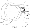
- FIG. 3 is a generalized diagrammatic representation of the airflow in RT mode demonstrating paired counter rotating vortices 42a, 42b created by the side profiles 44a and 44b of each periodic curve 40 from tip 46 to valley 48.
- the plurality of periodic curves 40 forming the serrated trailing edge 38 on the fan cowl 32 may be generally characterized as chevron shaped and may be shaped as "saw-tooth" curves 40a (seen in FIGs. 4A and 4B ), " sinusoidal" curves 40b (seen in FIGs. 5A and 5B ), “peaky sinusoidal” curves 40c (seen in FIGs. 6A and 6B ), or “sharp parabolic” curves 40d (seen in FIGs. 7A and 7B ) to accommodate specific engine designs and aerodynamic requirements.
- Saw tooth curves have substantially flat sides connecting in an inner vertex at each valley and an outer vertex at each tip.
- the sinusoidal curves are sinusoids with a power of 1.0 while the peaky sinusoidal curves are sinusoids with a power greater than one with the example shown being a power of 2.0.
- Sharp parabolic curves are parabolic curves originating in each valley and terminating at each tip with a sharp vertex or small radius.
- a chevron geometry is defined herein as a serration having an elliptic valley (for example with a radius R) and an elliptic tip (for example with a radius 1 ⁇ 2 R) connected by straight lines or with the valley and tip curves interconnecting at an inflection point.
- the maximum sweep angle, ⁇ (Theta), of these periodic curves, either for a straight section or at the inflection point 49, in exemplary implementations is greater than 25 degrees and is desirably at least 25-30 degrees, with a preferred value of between 45 and 60 degrees.
- Engines as exemplified in the implementations described herein employ stators or guide vanes for aerodynamic control of flow exiting the VPF 34 in the fan cowl 32.
- the guide vanes may be a single row or multiple rows extending aft of the VPF 34 but typically terminate in a row of outer guide vanes (OGVs) 50 as represented in FIG. 8 . Additional desirable flow control is achieved by synchronizing the number and clocking of the periodic curves 40 of the serrated trailing edge 38 with the OGVs 50.
- the number of OGVs in the plurality of OGVs 50 is NOGV
- the periodic curves 40 may be synchronized with the OGVs 50 by angular orientation with respect to the OGVs 50 (i.e. have clocking angle 51 relative to the OGVs) to accommodate swirl in the flow for optimized aerodynamic alignment of reverse flow entering through the OGVs 50 in RT mode.
- fan cowl length L1 is approximately 172.7-177.8 cm (68-70 inches) and maximum fan cowl outer diameter D1 is approximately 330-343 cm (130-135 inches).
- the inlet length L2 (from an inlet lip 52 to the VPF 34) is approximately 30.5-50.8 cm (12-20 inches) with a diameter D2 of the VPF 34 approximately 304.8 cm (120 inches).
- the exemplary implementations disclosed herein provide a method for controlling airflow for reverse thrust in an ultrashort nacelle as shown in FIG. 10 .
- a reverse flow is created through an exit plane of a fan cowl with a variable pitch fan (VPF) housed within the fan cowl and having a reverse thrust position, step 1002.
- the reverse flow is drawn across a serrated trailing edge of the fan cowl, step 1004.
- a plurality of periodic curves forming the serrated trailing edge induces vortices in the reverse flow, step 1006.
- the periodic curves are saw tooth, sinusoidal, peaky sinusoidal, sharp parabola or chevron geometries.
- the flow from each of the plurality of periodic curves is synchronized with associated outer guide vanes (OGVs) housed in the fan cowl, step 1008. Synchronization is achieved by matching the number of OGVs with integer multiples of the periodic curves and clocking of the periodic curves relative to associated OGVs for matching swirl characteristics in the reverse flow for smooth aerodynamic alignment.
- OGVs outer guide vanes
Abstract
Description
- The disclosure relates generally to fan cowls for turbofan aircraft engines and more particularly to fan cowls with a serrated trailing edge employed in ultrashort nacelles with variable pitch fans having reverse thrust capability.
- Large high bypass turbofan engines are employing ultrashort nacelles. Variable pitch fans with reverse thrust capability are being introduced into such turbofan engines and control of airflow in the fan cowl of an ultrashort nacelle is becoming increasingly important. In reverse thrust mode, particularly on initial activation when the aircraft is at a relatively high airspeed, incoming flow being drawn around the trailing edge to enter through the exit plane of the fan cowl must undergo significant turning and resulting flow separation from the internal surface of the fan cowl can be significant. With long fan cowls, the flow has some ability to reattach before reaching the fan. However, with ultrashort nacelles, the length of the fan cowl may be insufficient to provide reattachment and aerodynamic qualities of the reverse thrust produced by the fan may be reduced. A variable geometry nozzle (VAN) can be used to help alleviate the flow separation in reverse thrust mode. However, VANs are structurally and mechanically complex, may be expensive to manufacture, create weight penalties, and may require extensive maintenance.
- It is with respect to these and other considerations that the disclosure made herein is presented.
- Disclosed is an ultrashort nacelle configuration employing a fan cowl having an exit plane and a serrated trailing edge. A variable pitch fan is housed within the fan cowl. The variable pitch fan has a reverse thrust position, inducing a reverse flow through the exit plane and into the fan cowl. The serrated trailing edge forms a plurality of vortex generators configured to induce vortices in the reverse flow.
- The disclosure also refers to a method for controlling airflow for reverse thrust in an ultrashort nacelle. A reverse flow through an exit plane of a fan cowl is induced with a variable pitch fan housed within the fan cowl and having a reverse thrust position. The reverse flow is drawn across a serrated trailing edge of the fan cowl. Vortices in the reverse flow are induced with a plurality of periodic curves forming the serrated trailing edge.
- The features, functions, and advantages that have been discussed can be achieved independently in various implementations of the present disclosure or may be combined in yet other implementations further details of which can be seen with reference to the following description and drawings.
-
FIGs. 1A and1B are pictorial representations of a general configuration of a high bypass turbofan engine; -
FIGs. 2A ,2B and2C are a front pictorial representation, a side section representation and a rear pictorial representation of an exemplary implementation as described herein; -
FIG. 3 is a generalized diagrammatic representation of the airflow in the exemplary implementation in reverse thrust mode; -
FIGs. 4A and4B are side and rear pictorial representations of the fan cowl with an exemplary saw tooth configuration of the periodic curve in the serrated trailing edge of the fan cowl; -
FIGs. 5A and5B are side and rear pictorial representations of the fan cowl with an exemplary sinusoidal configuration of the periodic curve in the serrated trailing edge of the fan cowl; -
FIGs. 6A and6B are side and rear pictorial representations of the fan cowl with an exemplary peaky sinusoidal configuration of the periodic curve in the serrated trailing edge of the fan cowl; -
FIGs. 7A and7B are side and rear pictorial representations of the fan cowl with an exemplary sharp parabolic configuration of the periodic curve in the serrated trailing edge of the fan cowl; -
FIG. 8 is a partial section representation showing exemplary guide vanes in the fan cowl; -
FIG. 9 is a section representation of the exemplary implementation with relative dimensions; and, -
FIG. 10 is a flow chart showing a method for controlling airflow for reverse thrust in an ultrashort nacelle employing the disclosed implementation. - The disclosure described herein provides a fan cowl for use in an ultrashort nacelle for a turbofan engine employing a variable pitch fan (VPF) with reverse thrust capability. The fan cowl employs a serrated trailing edge (STE) with the periodic curves of the serrations acting as vortex generators (VGs) when the airflow is being drawn in from the exit plane around the trailing edge during reverse thrust (RT) operation. Without these VGs, the incoming flow would otherwise separate and greatly reduce the RT capability of the system. In normal operation, such as cruise, climb, take-off and landing, the STE-VGs are essentially inactive thereby minimizing aerodynamic losses and impact on specific fuel consumption.
- Referring to the drawings,
FIGs. 1A and1B show anaircraft 8 with a general configuration of an ultrahighbypass turbofan engine 10 with anacelle 12 having afan cowl 14 and acore nacelle 16. In a conventional engine, thefan cowl 14 has a substantially planartrailing edge 18. Thecore nacelle 16 is substantially concentric with thefan cowl 14, typically extending aft of thetrailing edge 18 and having anexhaust nozzle 20 for the engine core with aconcentric tail cone 22. Thenacelle 12 is typically suspended from anaircraft wing 24 with apylon 26. - As seen in
FIGs. 2A ,2B and2C an ultrahighbypass turbofan engine 28 with anultrashort nacelle 30 employs afan cowl 32 housing a variable pitch fan (VPF) 34. Thefan cowl 32 has anexit plane 36. In flight operations, takeoff, climb, cruise, descent and landing, airflow from the fan exits the fan cowl at the exit plane in an aft direction providing forward thrust for the aircraft. Upon landing, the VPF 34 may be placed into a reverse pitch providing a reverse thrust (RT) mode for theengine 28 to assist in decelerating the aircraft. In the RT condition, airflow is drawn through theexit plane 36 into thefan cowl 32 and advances forward through theVPF 34 rotating in reverse pitch. Thefan cowl 32 has a serratedtrailing edge 38. A plurality ofperiodic curves 40 extend around the circumference of the serratedtrailing edge 38 to provide the serrations. Each of theperiodic curves 40 acts as a vortex generator (VG) in the RT mode. The serratedtrailing edge 38 provides entirely passive flow control without moving mechanisms or active alteration of geometry. -
FIG. 3 is a generalized diagrammatic representation of the airflow in RT mode demonstrating pairedcounter rotating vortices side profiles periodic curve 40 fromtip 46 tovalley 48. - The plurality of
periodic curves 40 forming the serratedtrailing edge 38 on thefan cowl 32 may be generally characterized as chevron shaped and may be shaped as "saw-tooth"curves 40a (seen inFIGs. 4A and4B ), " sinusoidal"curves 40b (seen inFIGs. 5A and5B ), "peaky sinusoidal"curves 40c (seen inFIGs. 6A and6B ), or "sharp parabolic"curves 40d (seen inFIGs. 7A and7B ) to accommodate specific engine designs and aerodynamic requirements. Saw tooth curves have substantially flat sides connecting in an inner vertex at each valley and an outer vertex at each tip. The sinusoidal curves are sinusoids with a power of 1.0 while the peaky sinusoidal curves are sinusoids with a power greater than one with the example shown being a power of 2.0. Sharp parabolic curves are parabolic curves originating in each valley and terminating at each tip with a sharp vertex or small radius. For purposes of generalization, a chevron geometry is defined herein as a serration having an elliptic valley (for example with a radius R) and an elliptic tip (for example with a radius ½ R) connected by straight lines or with the valley and tip curves interconnecting at an inflection point. The maximum sweep angle, θ (Theta), of these periodic curves, either for a straight section or at theinflection point 49, in exemplary implementations is greater than 25 degrees and is desirably at least 25-30 degrees, with a preferred value of between 45 and 60 degrees. - Engines as exemplified in the implementations described herein employ stators or guide vanes for aerodynamic control of flow exiting the
VPF 34 in thefan cowl 32. The guide vanes may be a single row or multiple rows extending aft of theVPF 34 but typically terminate in a row of outer guide vanes (OGVs) 50 as represented inFIG. 8 . Additional desirable flow control is achieved by synchronizing the number and clocking of theperiodic curves 40 of theserrated trailing edge 38 with theOGVs 50. For example, if the number of OGVs in the plurality of OGVs 50 is NOGV, then the number of peaks/valleys (NPV) in the plurality of curves forming theserrated trailing edge 38 should be an integer multiple of NOGV (i.e. NPV/NOGV = an integer value. With this integer relationship, theperiodic curves 40 may be synchronized with theOGVs 50 by angular orientation with respect to the OGVs 50 (i.e. have clockingangle 51 relative to the OGVs) to accommodate swirl in the flow for optimized aerodynamic alignment of reverse flow entering through theOGVs 50 in RT mode. - In the example shown in
FIG. 9 (representation not to scale), fan cowl length L1 is approximately 172.7-177.8 cm (68-70 inches) and maximum fan cowl outer diameter D1 is approximately 330-343 cm (130-135 inches). The inlet length L2 (from aninlet lip 52 to the VPF 34) is approximately 30.5-50.8 cm (12-20 inches) with a diameter D2 of theVPF 34 approximately 304.8 cm (120 inches). The depth L3 of the serrations is approximately 15.2 cm (6 inches) dependent on configuration, sweep angle and number of periodic curves in the circumference. Ratios of defining geometry for this implementation are L1/D1 = 0.5-0.6, L2/D2 = 0.10-0.17. Desired L1/D1 for exemplary ultrahigh bypass turbofan engines in which implementations are most desirable is less than or equal to 1.0 and L2/D2 is less than or equal to 0.25. - The exemplary implementations disclosed herein provide a method for controlling airflow for reverse thrust in an ultrashort nacelle as shown in
FIG. 10 . A reverse flow is created through an exit plane of a fan cowl with a variable pitch fan (VPF) housed within the fan cowl and having a reverse thrust position,step 1002. The reverse flow is drawn across a serrated trailing edge of the fan cowl,step 1004. A plurality of periodic curves forming the serrated trailing edge induces vortices in the reverse flow,step 1006. As previously described, the periodic curves are saw tooth, sinusoidal, peaky sinusoidal, sharp parabola or chevron geometries. The flow from each of the plurality of periodic curves is synchronized with associated outer guide vanes (OGVs) housed in the fan cowl,step 1008. Synchronization is achieved by matching the number of OGVs with integer multiples of the periodic curves and clocking of the periodic curves relative to associated OGVs for matching swirl characteristics in the reverse flow for smooth aerodynamic alignment. - Further, the disclosure comprises the following clauses:
- 1. A nacelle configuration comprising:
- a fan cowl (32) having an exit plane (36) and a serrated trailing edge (38); and
- a variable pitch fan (VPF) (34) housed within the fan cowl (32), said VPF (34) having a reverse thrust position inducing a reverse flow through the exit plane (36) and into the fan cowl (32);
- wherein said serrated trailing edge (38) comprises a plurality of vortex generators configured to induce vortices in the reverse flow.
- 2. The nacelle configuration as defined in clause 1, wherein the serrated trailing edge (38) comprises a plurality of periodic curves (40) having at least one of a saw tooth, sinusoidal, peaky sinusoidal, sharp parabola and chevron geometry.
- 3. The nacelle configuration as defined in clause 2, wherein each of the plurality of periodic curves (40) has a maximum sweep angle of greater than 25 degrees.
- 4. The nacelle configuration as defined in clause 2 or 3, wherein each of the plurality of periodic curves (40) has a maximum sweep angle of at least 30 degrees.
- 5. The nacelle configuration as defined in any of the clauses 2 or 3, wherein each of the plurality of periodic curves (40) has a maximum sweep angle between 25 and 60 degrees.
- 6. The nacelle configuration as defined in any of the clauses 2-5, further comprising a plurality of outer guide vanes (OGVs (50)) housed within the fan cowl (32) and the plurality of periodic curves (40) in the serrated trailing edge (38) is synchronized with the plurality of OGVs (50).
- 7. The nacelle configuration as defined in clause 6, wherein a number of periodic curves (40) in the plurality of periodic curves (40) is an integer multiple of a number of OGVs (50) in the plurality of OGVs (50).
- 8. The nacelle configuration as defined in clause 6 or 7, wherein a clocking angle (51) of the plurality of periodic curves (40) with respect to the plurality of OGVs (50) provides aerodynamically aligned reverse flow into the plurality of OGVs (50).
- 9. The nacelle configuration as defined in any of the preceding clauses, wherein a length of the fan cowl (32) is less than or equal to a diameter of the VPF (34).
- 10. The nacelle configuration as defined in any of the preceding clauses, wherein the fan cowl (32) has an inlet length from an inlet lip (52) to the VPF (34) and the inlet length is less than 25 percent of a diameter of the VPF (34).
- 11. An aircraft engine comprising:
- a nacelle (12) having a fan cowl (32) and a core nacelle (12) (16) housing an engine (28) core, said fan cowl (32) having an exit plane (36) and a serrated trailing edge (38); and
- a variable pitch fan (VPF (34)) housed within the fan cowl (32) and engaged to the engine (28) core, said VPF (34) having a reverse thrust position inducing a reverse flow through the exit plane (36) and into the fan cowl (32);
- wherein said serrated trailing edge (38) comprises a plurality of vortex generators configured to induce vortices in the reverse flow.
- 12. The aircraft engine as defined in clause 11, wherein said core nacelle (12) (16) is concentric to the fan cowl (32) and extends through the exit plane (36).
- 13. The aircraft engine as defined in
clause 11 or 12, wherein the serrated trailing edge (38) comprises a plurality of periodic curves (40) having at least one of saw tooth, sinusoidal, peaky sinusoidal, sharp parabola and chevron geometry. - 14. The aircraft engine as defined in clause 13, wherein each of the plurality of periodic curves (40) has a maximum sweep angle of greater than 25 degrees.
- 15. The aircraft engine as defined in
clause 13 or 14, further comprising a plurality of outer guide vanes (OGVs (50)) housed within the fan cowl (32) wherein a number of periodic curves (40) in the plurality of periodic curves (40) is an integer multiple of a number of OGVs (50) in the plurality of OGVs (50). - 16. The aircraft engine as defined in clause 15, wherein a clocking angle (51) of the plurality of periodic curves (40) with respect to the plurality of OGVs (50) provides aerodynamically aligned reverse flow into the plurality of OGVs (50).
- 17. A method for controlling airflow for reverse thrust in a nacelle (12), the method comprising:
- inducing a reverse flow through an exit plane (36) of a fan cowl (32) wherein a variable pitch fan (VPF0 (34) having a reverse thrust position is housed within the fan cowl (32);
- drawing the reverse flow across a serrated trailing edge (38) of the fan cowl (32); and
- inducing vortices in the reverse flow with a plurality of periodic curves (40) comprising the serrated trailing edge (38).
- 18. The method as defined in clause 17, wherein the plurality of periodic curves (40) comprises at least one of a saw tooth, sinusoidal, peaky sinusoidal, sharp parabola and chevron geometry.
- 19. The method as defined in
clause 17 or 18, further comprises synchronizing the reverse flow drawn across each of the plurality of periodic curves (40) with an associated outer guide vane (OGV) of a plurality of OGVs (50) housed in the fan cowl (32). - 20. The method as defined in clause 19 wherein a number of periodic curves (40) in the plurality of periodic curves (40) is an integer multiple of a number of OGVs (50) in the plurality of OGVs (50).
- 21. The method as defined in
clause 19 or 20, wherein the periodic curves (40) in the plurality of periodic curves (40) have a clocking angle (51) with respect to associated OGVs (50) in the plurality of OGVs (50) to aerodynamically align reverse flow into the plurality of OGVs (50). - Having now described various implementations of the disclosure in detail as required by the patent statutes, those skilled in the art will recognize modifications and substitutions to the specific implementations disclosed herein. Such modifications are within the scope and intent of the present disclosure as defined in the following claims.
Claims (15)
- A nacelle configuration comprising:a fan cowl (32) having an exit plane (36) and a serrated trailing edge (38); anda variable pitch fan (VPF) (34) housed within the fan cowl (32), said VPF (34) having a reverse thrust position inducing a reverse flow through the exit plane (36) and into the fan cowl (32);wherein said serrated trailing edge (38) comprises a plurality of vortex generators configured to induce vortices in the reverse flow.
- The nacelle configuration as defined in claim 1, wherein the serrated trailing edge (38) comprises a plurality of periodic curves (40) having at least one of a saw tooth, sinusoidal, peaky sinusoidal, sharp parabola and chevron geometry.
- The nacelle configuration as defined in claim 2, wherein each of the plurality of periodic curves (40) has a maximum sweep angle of greater than 25 degrees.
- The nacelle configuration as defined in claim 2 or 3, wherein each of the plurality of periodic curves (40) has a maximum sweep angle of at least 30 degrees.
- The nacelle configuration as defined in claims 2 or 3, wherein each of the plurality of periodic curves (40) has a maximum sweep angle between 25 and 60 degrees.
- The nacelle configuration as defined in any of the preceding claims 2-5, further comprising a plurality of outer guide vanes (OGVs (50)) housed within the fan cowl (32) and the plurality of periodic curves (40) in the serrated trailing edge (38) is synchronized with the plurality of OGVs (50).
- The nacelle configuration as defined in claim 6, wherein a number of periodic curves (40) in the plurality of periodic curves (40) is an integer multiple of a number of OGVs (50) in the plurality of OGVs (50).
- The nacelle configuration as defined in claims 6 or 7, wherein a clocking angle (51) of the plurality of periodic curves (40) with respect to the plurality of OGVs (50) provides aerodynamically aligned reverse flow into the plurality of OGVs (50).
- The nacelle configuration as defined in any of the preceding claims, wherein a length of the fan cowl (32) is less than or equal to a diameter of the VPF (34).
- The nacelle configuration as defined in any of the preceding claims, wherein the fan cowl (32) has an inlet length from an inlet lip (52) to the VPF (34) and the inlet length is less than 25 percent of a diameter of the VPF (34).
- A method for controlling airflow for reverse thrust in a nacelle (12), the method comprising:inducing a reverse flow through an exit plane (36) of a fan cowl (32) wherein a variable pitch fan (VPF0 (34) having a reverse thrust position is housed within the fan cowl (32);drawing the reverse flow across a serrated trailing edge (38) of the fan cowl (32); andinducing vortices in the reverse flow with a plurality of periodic curves (40) comprising the serrated trailing edge (38).
- The method as defined in claim 11, wherein the plurality of periodic curves (40) comprises at least one of a saw tooth, sinusoidal, peaky sinusoidal, sharp parabola and chevron geometry.
- The method as defined in claim 11 or 12, further comprises synchronizing the reverse flow drawn across each of the plurality of periodic curves (40) with an associated outer guide vane (OGV) of a plurality of OGVs (50) housed in the fan cowl (32).
- The method as defined in claim 13, wherein a number of periodic curves (40) in the plurality of periodic curves (40) is an integer multiple of a number of OGVs (50) in the plurality of OGVs (50), and/or
wherein the periodic curves (40) in the plurality of periodic curves (40) have a clocking angle (51) with respect to associated OGVs (50) in the plurality of OGVs (50) to aerodynamically align reverse flow into the plurality of OGVs (50). - An aircraft engine comprising a nacelle configuration according to any of the preceding claims 1-10.
Applications Claiming Priority (1)
| Application Number | Priority Date | Filing Date | Title |
|---|---|---|---|
| US15/801,105 US11053888B2 (en) | 2017-11-01 | 2017-11-01 | Fan cowl with a serrated trailing edge providing attached flow in reverse thrust mode |
Publications (1)
| Publication Number | Publication Date |
|---|---|
| EP3480448A1 true EP3480448A1 (en) | 2019-05-08 |
Family
ID=64109765
Family Applications (1)
| Application Number | Title | Priority Date | Filing Date |
|---|---|---|---|
| EP18203949.5A Pending EP3480448A1 (en) | 2017-11-01 | 2018-11-01 | Fan cowl with a serrated trailing edge providing attached flow in reverse thrust mode |
Country Status (6)
| Country | Link |
|---|---|
| US (1) | US11053888B2 (en) |
| EP (1) | EP3480448A1 (en) |
| JP (1) | JP7209507B2 (en) |
| CN (1) | CN109751284B (en) |
| CA (1) | CA3021411C (en) |
| RU (1) | RU2018135680A (en) |
Cited By (2)
| Publication number | Priority date | Publication date | Assignee | Title |
|---|---|---|---|---|
| FR3127788A1 (en) * | 2021-10-04 | 2023-04-07 | Safran Aircraft Engines | Outlet nozzle fitted with chevrons for an aeronautical thruster |
| KR20230122383A (en) * | 2022-02-14 | 2023-08-22 | 국방과학연구소 | Method of designing saw tooth-shape cowl lip profile modeling |
Families Citing this family (3)
| Publication number | Priority date | Publication date | Assignee | Title |
|---|---|---|---|---|
| US11485471B2 (en) * | 2017-08-25 | 2022-11-01 | United States Of America As Represented By The Administrator Of Nasa | Application of leading edge serration and trailing edge foam for undercarriage wheel cavity noise reduction |
| FR3120254B1 (en) | 2021-03-01 | 2023-03-10 | Safran Aircraft Engines | Aircraft propulsion unit nacelle air inlet for promoting a thrust phase and a thrust reversal phase and method of use thereof |
| CN114715416A (en) * | 2022-03-22 | 2022-07-08 | 中国商用飞机有限责任公司北京民用飞机技术研究中心 | Aviation turbofan engine and outer duct nozzle |
Citations (2)
| Publication number | Priority date | Publication date | Assignee | Title |
|---|---|---|---|---|
| US20100115958A1 (en) * | 2008-11-11 | 2010-05-13 | The Boeing Company | Radially translating fan nozzle nacelle |
| US20160146113A1 (en) * | 2014-11-21 | 2016-05-26 | General Electric Company | Gas turbine engine and method of assembling the same |
Family Cites Families (27)
| Publication number | Priority date | Publication date | Assignee | Title |
|---|---|---|---|---|
| US5090196A (en) * | 1989-07-21 | 1992-02-25 | The Boeing Company | Ducted fan type gas turbine engine power plants |
| DE4039810C1 (en) * | 1990-12-13 | 1991-10-17 | Mtu Muenchen Gmbh | |
| US5169288A (en) * | 1991-09-06 | 1992-12-08 | General Electric Company | Low noise fan assembly |
| GB2289921A (en) * | 1994-06-03 | 1995-12-06 | A E Harris Limited | Nozzle for turbofan aeroengines |
| DE19634296C2 (en) | 1996-08-24 | 1999-04-22 | Erich Dipl Ing Ufer | Blower engine for aircraft with facilities for boundary layer extraction |
| US6360528B1 (en) * | 1997-10-31 | 2002-03-26 | General Electric Company | Chevron exhaust nozzle for a gas turbine engine |
| US7578132B2 (en) * | 2001-03-03 | 2009-08-25 | Rolls-Royce Plc | Gas turbine engine exhaust nozzle |
| US6532729B2 (en) * | 2001-05-31 | 2003-03-18 | General Electric Company | Shelf truncated chevron exhaust nozzle for reduction of exhaust noise and infrared (IR) signature |
| US7093423B2 (en) | 2004-01-20 | 2006-08-22 | General Electric Company | Methods and apparatus for operating gas turbine engines |
| FR2873166B1 (en) * | 2004-07-13 | 2008-10-31 | Snecma Moteurs Sa | TURBOMACHINE TUBE WITH PATTERNS WITH JET NOISE REDUCTION |
| US7340883B2 (en) * | 2004-11-12 | 2008-03-11 | The Boeing Company | Morphing structure |
| FR2890696B1 (en) | 2005-09-12 | 2010-09-17 | Airbus France | TURBOMOTEUR WITH ATTENUATED JET NOISE |
| US8157207B2 (en) * | 2006-08-09 | 2012-04-17 | The Boeing Company | Jet engine nozzle exit configurations, including projections oriented relative to pylons, and associated systems and methods |
| US20160052621A1 (en) * | 2009-07-10 | 2016-02-25 | Peter Ireland | Energy efficiency improvements for turbomachinery |
| US8713911B2 (en) * | 2010-12-15 | 2014-05-06 | Woodward Hrt, Inc. | System and method for operating a thrust reverser for a turbofan propulsion system |
| FR2981989B1 (en) * | 2011-10-31 | 2013-11-01 | Aircelle Sa | MOBILE SCREW REVERSE INVERTER AND MONOBLOC MOBILE HOOD |
| FR2997681B1 (en) * | 2012-11-08 | 2015-05-15 | Snecma | PLANE PROPELLED BY A TURBOREACTOR WITH CONTRAROTATIVE BLOWERS |
| NZ710406A (en) | 2013-01-25 | 2017-11-24 | Peter Ireland | Energy efficiency improvements for turbomachinery |
| CN104196649A (en) | 2014-06-05 | 2014-12-10 | 中国航空工业集团公司沈阳发动机设计研究所 | Novel blocking binary rotation flow central body structure |
| US10072511B2 (en) | 2014-10-02 | 2018-09-11 | Rolls-Royce North American Technologies Inc. | Engine nacelle |
| CN204253209U (en) | 2014-11-24 | 2015-04-08 | 江西洪都航空工业集团有限责任公司 | A kind of venting gas appliance of aircraft engine |
| US9963981B2 (en) * | 2015-06-10 | 2018-05-08 | General Electric Company | Pitch change mechanism for shrouded fan with low fan pressure ratio |
| US9835037B2 (en) * | 2015-06-22 | 2017-12-05 | General Electric Company | Ducted thrust producing system with asynchronous fan blade pitching |
| US10443412B2 (en) * | 2015-08-28 | 2019-10-15 | General Electric Company | Variable pitch fan pitch range limiter |
| US20170167438A1 (en) * | 2015-12-11 | 2017-06-15 | General Electric Company | Gas Turbine Engine |
| US10724541B2 (en) | 2015-12-31 | 2020-07-28 | United Technologies Corporation | Nacelle short inlet |
| US20170218975A1 (en) * | 2016-01-29 | 2017-08-03 | United Technologies Corporation | Variable pitch fan blade arrangement for gas turbine engine |
-
2017
- 2017-11-01 US US15/801,105 patent/US11053888B2/en active Active
-
2018
- 2018-10-10 RU RU2018135680A patent/RU2018135680A/en unknown
- 2018-10-11 JP JP2018192472A patent/JP7209507B2/en active Active
- 2018-10-19 CA CA3021411A patent/CA3021411C/en active Active
- 2018-10-31 CN CN201811285159.7A patent/CN109751284B/en active Active
- 2018-11-01 EP EP18203949.5A patent/EP3480448A1/en active Pending
Patent Citations (2)
| Publication number | Priority date | Publication date | Assignee | Title |
|---|---|---|---|---|
| US20100115958A1 (en) * | 2008-11-11 | 2010-05-13 | The Boeing Company | Radially translating fan nozzle nacelle |
| US20160146113A1 (en) * | 2014-11-21 | 2016-05-26 | General Electric Company | Gas turbine engine and method of assembling the same |
Cited By (3)
| Publication number | Priority date | Publication date | Assignee | Title |
|---|---|---|---|---|
| FR3127788A1 (en) * | 2021-10-04 | 2023-04-07 | Safran Aircraft Engines | Outlet nozzle fitted with chevrons for an aeronautical thruster |
| WO2023057704A1 (en) * | 2021-10-04 | 2023-04-13 | Safran Aircraft Engines | Outlet nozzle provided with chevrons for aeronautical thruster |
| KR20230122383A (en) * | 2022-02-14 | 2023-08-22 | 국방과학연구소 | Method of designing saw tooth-shape cowl lip profile modeling |
Also Published As
| Publication number | Publication date |
|---|---|
| JP7209507B2 (en) | 2023-01-20 |
| RU2018135680A3 (en) | 2022-03-17 |
| US11053888B2 (en) | 2021-07-06 |
| JP2019085097A (en) | 2019-06-06 |
| US20190128214A1 (en) | 2019-05-02 |
| CN109751284A (en) | 2019-05-14 |
| CA3021411A1 (en) | 2019-05-01 |
| BR102018071840A8 (en) | 2023-02-23 |
| BR102018071840A2 (en) | 2019-06-04 |
| CN109751284B (en) | 2021-03-30 |
| RU2018135680A (en) | 2020-04-10 |
| CA3021411C (en) | 2023-06-27 |
Similar Documents
| Publication | Publication Date | Title |
|---|---|---|
| CA3021411C (en) | Fan cowl with a serrated trailing edge providing attached flow in reverse thrust mode | |
| US10907495B2 (en) | Unducted thrust producing system | |
| US20130156583A1 (en) | Airfoils including tip profile for noise reduction and method for fabricating same | |
| JP5489727B2 (en) | Aircraft engine | |
| US4993663A (en) | Hybrid laminar flow nacelle | |
| EP1206384B1 (en) | Supersonic external-compression diffuser and method for designing same | |
| US7395657B2 (en) | Flade gas turbine engine with fixed geometry inlet | |
| US8689538B2 (en) | Ultra-efficient propulsor with an augmentor fan circumscribing a turbofan | |
| US10723434B2 (en) | Aircraft propulsion unit comprising an unducted-fan turbine engine and an attachment pylon | |
| EP3093437A1 (en) | Immersed core flow inlet between rotor blade and stator vane for an unducted fan gas turbine | |
| EP3284942B1 (en) | Direct drive aft fan engine | |
| EP2685065B1 (en) | Propeller gas turbine engine | |
| US20180354634A1 (en) | A turbine engine propelled airplane having an acoustic baffle | |
| US10035582B2 (en) | Propeller blade for a turbomachine | |
| EP3002210B1 (en) | Engine nacelle | |
| EP2964890B1 (en) | Rotor noise suppression | |
| US10974813B2 (en) | Engine nacelle for an aircraft | |
| EP3249203A1 (en) | Aircraft gas turbine engine nacelle | |
| US11549383B2 (en) | Variable geometry aerodynamic blade with integral shape memory actuation | |
| US11338901B2 (en) | Nacelle for a boundary layer ingestion propulsor | |
| EP2971614B1 (en) | A subsonic shock strut | |
| EP3643877A1 (en) | Ducted propulsor with airfoils having a leading edge with a deflected region | |
| US20150354501A1 (en) | Non-Axisymmetric Exit Guide Vane Design | |
| Denning et al. | Future trends in aero gas turbine design—unconventional engines | |
| JPH10238305A (en) | Curved propeller and curved turbine |
Legal Events
| Date | Code | Title | Description |
|---|---|---|---|
| PUAI | Public reference made under article 153(3) epc to a published international application that has entered the european phase |
Free format text: ORIGINAL CODE: 0009012 |
|
| STAA | Information on the status of an ep patent application or granted ep patent |
Free format text: STATUS: REQUEST FOR EXAMINATION WAS MADE |
|
| STAA | Information on the status of an ep patent application or granted ep patent |
Free format text: STATUS: REQUEST FOR EXAMINATION WAS MADE |
|
| 17P | Request for examination filed |
Effective date: 20181101 |
|
| AK | Designated contracting states |
Kind code of ref document: A1 Designated state(s): AL AT BE BG CH CY CZ DE DK EE ES FI FR GB GR HR HU IE IS IT LI LT LU LV MC MK MT NL NO PL PT RO RS SE SI SK SM TR |
|
| AX | Request for extension of the european patent |
Extension state: BA ME |
|
| STAA | Information on the status of an ep patent application or granted ep patent |
Free format text: STATUS: EXAMINATION IS IN PROGRESS |
|
| 17Q | First examination report despatched |
Effective date: 20210331 |
|
| STAA | Information on the status of an ep patent application or granted ep patent |
Free format text: STATUS: EXAMINATION IS IN PROGRESS |
|
| RAP3 | Party data changed (applicant data changed or rights of an application transferred) |
Owner name: THE BOEING COMPANY |