EP2964890B1 - Rotor noise suppression - Google Patents
Rotor noise suppression Download PDFInfo
- Publication number
- EP2964890B1 EP2964890B1 EP13872275.6A EP13872275A EP2964890B1 EP 2964890 B1 EP2964890 B1 EP 2964890B1 EP 13872275 A EP13872275 A EP 13872275A EP 2964890 B1 EP2964890 B1 EP 2964890B1
- Authority
- EP
- European Patent Office
- Prior art keywords
- rotatable blade
- open rotor
- aperture
- turbine engine
- exhaust gas
- Prior art date
- Legal status (The legal status is an assumption and is not a legal conclusion. Google has not performed a legal analysis and makes no representation as to the accuracy of the status listed.)
- Active
Links
- 230000001629 suppression Effects 0.000 title description 3
- 239000012530 fluid Substances 0.000 claims description 26
- 238000011144 upstream manufacturing Methods 0.000 claims description 10
- 238000002485 combustion reaction Methods 0.000 claims description 8
- 238000000034 method Methods 0.000 claims description 8
- 238000004891 communication Methods 0.000 claims description 4
- 239000000446 fuel Substances 0.000 claims 2
- 230000003993 interaction Effects 0.000 claims 2
- 239000000203 mixture Substances 0.000 claims 1
- 230000001105 regulatory effect Effects 0.000 claims 1
- 238000001816 cooling Methods 0.000 description 3
- 238000012986 modification Methods 0.000 description 2
- 230000004048 modification Effects 0.000 description 2
- 230000003044 adaptive effect Effects 0.000 description 1
- 230000004075 alteration Effects 0.000 description 1
- 238000005516 engineering process Methods 0.000 description 1
- 230000001737 promoting effect Effects 0.000 description 1
Images

Classifications
-
- F—MECHANICAL ENGINEERING; LIGHTING; HEATING; WEAPONS; BLASTING
- F02—COMBUSTION ENGINES; HOT-GAS OR COMBUSTION-PRODUCT ENGINE PLANTS
- F02C—GAS-TURBINE PLANTS; AIR INTAKES FOR JET-PROPULSION PLANTS; CONTROLLING FUEL SUPPLY IN AIR-BREATHING JET-PROPULSION PLANTS
- F02C7/00—Features, components parts, details or accessories, not provided for in, or of interest apart form groups F02C1/00 - F02C6/00; Air intakes for jet-propulsion plants
- F02C7/24—Heat or noise insulation
-
- B—PERFORMING OPERATIONS; TRANSPORTING
- B64—AIRCRAFT; AVIATION; COSMONAUTICS
- B64C—AEROPLANES; HELICOPTERS
- B64C11/00—Propellers, e.g. of ducted type; Features common to propellers and rotors for rotorcraft
- B64C11/46—Arrangements of, or constructional features peculiar to, multiple propellers
- B64C11/48—Units of two or more coaxial propellers
-
- F—MECHANICAL ENGINEERING; LIGHTING; HEATING; WEAPONS; BLASTING
- F01—MACHINES OR ENGINES IN GENERAL; ENGINE PLANTS IN GENERAL; STEAM ENGINES
- F01D—NON-POSITIVE DISPLACEMENT MACHINES OR ENGINES, e.g. STEAM TURBINES
- F01D5/00—Blades; Blade-carrying members; Heating, heat-insulating, cooling or antivibration means on the blades or the members
- F01D5/12—Blades
- F01D5/14—Form or construction
- F01D5/141—Shape, i.e. outer, aerodynamic form
- F01D5/142—Shape, i.e. outer, aerodynamic form of the blades of successive rotor or stator blade-rows
-
- F—MECHANICAL ENGINEERING; LIGHTING; HEATING; WEAPONS; BLASTING
- F02—COMBUSTION ENGINES; HOT-GAS OR COMBUSTION-PRODUCT ENGINE PLANTS
- F02C—GAS-TURBINE PLANTS; AIR INTAKES FOR JET-PROPULSION PLANTS; CONTROLLING FUEL SUPPLY IN AIR-BREATHING JET-PROPULSION PLANTS
- F02C3/00—Gas-turbine plants characterised by the use of combustion products as the working fluid
- F02C3/04—Gas-turbine plants characterised by the use of combustion products as the working fluid having a turbine driving a compressor
- F02C3/06—Gas-turbine plants characterised by the use of combustion products as the working fluid having a turbine driving a compressor the compressor comprising only axial stages
- F02C3/067—Gas-turbine plants characterised by the use of combustion products as the working fluid having a turbine driving a compressor the compressor comprising only axial stages having counter-rotating rotors
-
- F—MECHANICAL ENGINEERING; LIGHTING; HEATING; WEAPONS; BLASTING
- F02—COMBUSTION ENGINES; HOT-GAS OR COMBUSTION-PRODUCT ENGINE PLANTS
- F02C—GAS-TURBINE PLANTS; AIR INTAKES FOR JET-PROPULSION PLANTS; CONTROLLING FUEL SUPPLY IN AIR-BREATHING JET-PROPULSION PLANTS
- F02C6/00—Plural gas-turbine plants; Combinations of gas-turbine plants with other apparatus; Adaptations of gas-turbine plants for special use
- F02C6/20—Adaptations of gas-turbine plants for driving vehicles
- F02C6/206—Adaptations of gas-turbine plants for driving vehicles the vehicles being airscrew driven
-
- F—MECHANICAL ENGINEERING; LIGHTING; HEATING; WEAPONS; BLASTING
- F02—COMBUSTION ENGINES; HOT-GAS OR COMBUSTION-PRODUCT ENGINE PLANTS
- F02K—JET-PROPULSION PLANTS
- F02K3/00—Plants including a gas turbine driving a compressor or a ducted fan
- F02K3/02—Plants including a gas turbine driving a compressor or a ducted fan in which part of the working fluid by-passes the turbine and combustion chamber
- F02K3/025—Plants including a gas turbine driving a compressor or a ducted fan in which part of the working fluid by-passes the turbine and combustion chamber the by-pass flow being at least partly used to create an independent thrust component
-
- B—PERFORMING OPERATIONS; TRANSPORTING
- B64—AIRCRAFT; AVIATION; COSMONAUTICS
- B64C—AEROPLANES; HELICOPTERS
- B64C2230/00—Boundary layer controls
- B64C2230/04—Boundary layer controls by actively generating fluid flow
-
- B—PERFORMING OPERATIONS; TRANSPORTING
- B64—AIRCRAFT; AVIATION; COSMONAUTICS
- B64C—AEROPLANES; HELICOPTERS
- B64C2230/00—Boundary layer controls
- B64C2230/14—Boundary layer controls achieving noise reductions
-
- B—PERFORMING OPERATIONS; TRANSPORTING
- B64—AIRCRAFT; AVIATION; COSMONAUTICS
- B64C—AEROPLANES; HELICOPTERS
- B64C2230/00—Boundary layer controls
- B64C2230/16—Boundary layer controls by blowing other fluids over the surface than air, e.g. He, H, O2 or exhaust gases
-
- B—PERFORMING OPERATIONS; TRANSPORTING
- B64—AIRCRAFT; AVIATION; COSMONAUTICS
- B64C—AEROPLANES; HELICOPTERS
- B64C2230/00—Boundary layer controls
- B64C2230/28—Boundary layer controls at propeller or rotor blades
-
- B—PERFORMING OPERATIONS; TRANSPORTING
- B64—AIRCRAFT; AVIATION; COSMONAUTICS
- B64D—EQUIPMENT FOR FITTING IN OR TO AIRCRAFT; FLIGHT SUITS; PARACHUTES; ARRANGEMENT OR MOUNTING OF POWER PLANTS OR PROPULSION TRANSMISSIONS IN AIRCRAFT
- B64D27/00—Arrangement or mounting of power plants in aircraft; Aircraft characterised by the type or position of power plants
- B64D2027/005—Aircraft with an unducted turbofan comprising contra-rotating rotors, e.g. contra-rotating open rotors [CROR]
-
- F—MECHANICAL ENGINEERING; LIGHTING; HEATING; WEAPONS; BLASTING
- F05—INDEXING SCHEMES RELATING TO ENGINES OR PUMPS IN VARIOUS SUBCLASSES OF CLASSES F01-F04
- F05D—INDEXING SCHEME FOR ASPECTS RELATING TO NON-POSITIVE-DISPLACEMENT MACHINES OR ENGINES, GAS-TURBINES OR JET-PROPULSION PLANTS
- F05D2220/00—Application
- F05D2220/30—Application in turbines
- F05D2220/32—Application in turbines in gas turbines
- F05D2220/324—Application in turbines in gas turbines to drive unshrouded, low solidity propeller
-
- F—MECHANICAL ENGINEERING; LIGHTING; HEATING; WEAPONS; BLASTING
- F05—INDEXING SCHEMES RELATING TO ENGINES OR PUMPS IN VARIOUS SUBCLASSES OF CLASSES F01-F04
- F05D—INDEXING SCHEME FOR ASPECTS RELATING TO NON-POSITIVE-DISPLACEMENT MACHINES OR ENGINES, GAS-TURBINES OR JET-PROPULSION PLANTS
- F05D2220/00—Application
- F05D2220/30—Application in turbines
- F05D2220/32—Application in turbines in gas turbines
- F05D2220/325—Application in turbines in gas turbines to drive unshrouded, high solidity propeller
-
- F—MECHANICAL ENGINEERING; LIGHTING; HEATING; WEAPONS; BLASTING
- F05—INDEXING SCHEMES RELATING TO ENGINES OR PUMPS IN VARIOUS SUBCLASSES OF CLASSES F01-F04
- F05D—INDEXING SCHEME FOR ASPECTS RELATING TO NON-POSITIVE-DISPLACEMENT MACHINES OR ENGINES, GAS-TURBINES OR JET-PROPULSION PLANTS
- F05D2260/00—Function
- F05D2260/60—Fluid transfer
-
- F—MECHANICAL ENGINEERING; LIGHTING; HEATING; WEAPONS; BLASTING
- F05—INDEXING SCHEMES RELATING TO ENGINES OR PUMPS IN VARIOUS SUBCLASSES OF CLASSES F01-F04
- F05D—INDEXING SCHEME FOR ASPECTS RELATING TO NON-POSITIVE-DISPLACEMENT MACHINES OR ENGINES, GAS-TURBINES OR JET-PROPULSION PLANTS
- F05D2260/00—Function
- F05D2260/96—Preventing, counteracting or reducing vibration or noise
-
- Y—GENERAL TAGGING OF NEW TECHNOLOGICAL DEVELOPMENTS; GENERAL TAGGING OF CROSS-SECTIONAL TECHNOLOGIES SPANNING OVER SEVERAL SECTIONS OF THE IPC; TECHNICAL SUBJECTS COVERED BY FORMER USPC CROSS-REFERENCE ART COLLECTIONS [XRACs] AND DIGESTS
- Y02—TECHNOLOGIES OR APPLICATIONS FOR MITIGATION OR ADAPTATION AGAINST CLIMATE CHANGE
- Y02T—CLIMATE CHANGE MITIGATION TECHNOLOGIES RELATED TO TRANSPORTATION
- Y02T50/00—Aeronautics or air transport
- Y02T50/10—Drag reduction
-
- Y—GENERAL TAGGING OF NEW TECHNOLOGICAL DEVELOPMENTS; GENERAL TAGGING OF CROSS-SECTIONAL TECHNOLOGIES SPANNING OVER SEVERAL SECTIONS OF THE IPC; TECHNICAL SUBJECTS COVERED BY FORMER USPC CROSS-REFERENCE ART COLLECTIONS [XRACs] AND DIGESTS
- Y02—TECHNOLOGIES OR APPLICATIONS FOR MITIGATION OR ADAPTATION AGAINST CLIMATE CHANGE
- Y02T—CLIMATE CHANGE MITIGATION TECHNOLOGIES RELATED TO TRANSPORTATION
- Y02T50/00—Aeronautics or air transport
- Y02T50/60—Efficient propulsion technologies, e.g. for aircraft
Definitions
- the airfoil member 120 and the airfoil member 314 can be counter rotating relative to one another such that the airfoil member 120 can be rotated in a first direction 308 and the airfoil 314 can be rotated in a second direction 310, the first direction 308 being opposite the second direction 310.
Landscapes
- Engineering & Computer Science (AREA)
- Chemical & Material Sciences (AREA)
- Combustion & Propulsion (AREA)
- Mechanical Engineering (AREA)
- General Engineering & Computer Science (AREA)
- Aviation & Aerospace Engineering (AREA)
- Physics & Mathematics (AREA)
- Fluid Mechanics (AREA)
- Turbine Rotor Nozzle Sealing (AREA)
- Structures Of Non-Positive Displacement Pumps (AREA)
Description
- The present invention generally relates to reduction in noise of rotor blades, and more particularly, but not exclusively, to the noise reduction of open rotor blades driven by gas turbine engines.
- Noise suppression techniques useful with bladed rotors that are driven by internal combustion engines, such as a gas turbine engine, remains an area of interest. Some existing systems have various shortcomings relative to certain applications. Accordingly, there remains a need for further contributions in this area of technology.
-
EP2090765A2 discloses a propulsion system including a first row of propeller blades 16A which rotate about an axis, an annular cooling flow nozzle about an axis, the annular cooling flow nozzle upstream of the first row of propeller blades, and an annular exhaust nozzle 14 about an axis radially outboard of the annular cooling flow nozzle, the annular exhaust nozzle upstream of the first row of propeller blades. -
US20100124500A1 discloses a turbomachine having two unducted external fans mounted to contrarotate about a common axis. - The subject matter of the present invention refers to an apparatus comprising the features of claim 1. A method comprises the features of claim 9.
- Further embodiments, forms, features, aspects, benefits, and advantages of the present application shall become apparent from the description and figures provided herewith.
- The description herein makes reference to the accompanying drawings wherein like reference numerals refer to like parts throughout the several views, and wherein:
-
FIG. 1 depicts an embodiment of an internal combustion engine operable to power an aircraft. -
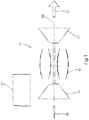
FIG. 2 depicts an airfoil member in communication with a fluid source to reduce rotor noise. -
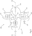
FIG. 3 depicts an embodiment of a rotor noise suppression system utilized in an open rotor configuration. - For purposes of promoting an understanding of the principles of the invention, reference will now be made to the embodiments illustrated in the drawings and specific language will be used to describe the same. It will nevertheless be understood that no limitation of the scope of the invention is thereby intended, such alterations and further modifications in the illustrated device, and such further applications of the principles of the invention as illustrated therein being contemplated as would normally occur to one skilled in the art to which the invention relates.
- With reference to
FIG. 1 , one embodiment is disclosed of aninternal combustion engine 50 useful to provide a power to anaircraft 51 which can take the form of mechanical and/or electrical power to drive, for example, accessories associated with either or both of theengine 50 andaircraft 51. - The
internal combustion engine 50 is depicted in the form of a gas turbine engine. - As used herein, the term "aircraft" includes, but is not limited to, helicopters, airplanes, unmanned space vehicles, fixed wing vehicles, variable wing vehicles, rotary wing vehicles, unmanned combat aerial vehicles, tailless aircraft, and other airborne vehicles.
- In the illustrated embodiment, the
internal combustion engine 50 includes acompressor 52,combustor 54, andturbine 56 which together are used together to produce a useful power. Though thegas turbine engine 50 is disclosed as a single spool turbojet engine, in other embodiments thegas turbine engine 50 can be a multi spool engine. In any number of embodiments thegas turbine engine 50 can be an axial flow, centrifugal flow, or mixed flow engine. In some embodiments thegas turbine engine 50 can be an adaptive and/or variable cycle engine. - With reference to
FIG. 2 , arotatable airfoil member 120 is depicted and includes a leadingedge 104, atrailing edge 112, and amean camber line 102. Therotatable airfoil member 120 is structured to be drivingly rotated about an axis such as an engine axis associated with thegas turbine engine 50. In one form therotatable airfoil member 120 is an open rotor structured to rotate about a centerline of the gas turbine engine. Theairfoil member 120 includes at least one
aperture 110 in flow communication with afluid source 108, and through which a fluid can be ejected that originates with thefluid source 108. Thefluid source 108 is a fluid flow path within thegas turbine engine 50 that conveys products of combustion produced in thecombustor 54 and that is ultimately exhausted from thegas turbine engine 50 through theturbine 56 and out a discharge opening. As used herein, therefore, the term "exhaust flow" includes flow at the discharge opening, as well as flow produced from thecombustor 54 that is being exhausted through theturbine 56. Thefluid source 108 can be a flow path through theturbine 56, or a flow path located between theturbine 56 and a discharge opening through which an exhaust flow exits thegas turbine engine 50 and/oraircraft 51. Thefluid source 108 can pick up flow from any position within theturbine 56, for example at an upstream, midstream, or downstream stage of theturbine 56. In some forms the fluid source can pick up flow after a final stage of theturbine 56 and before the discharge opening. - In the illustrated embodiment a plurality of the
apertures 110 are disposed radially outwardly along the span of theairfoil member 120. Theaperture 110 can take any variety of forms and shapes such as round or oblong form, a singular slot or series of slots disposed along theairfoil member 120, etc. Not all apertures associated with theairfoil member 120 need be the same. Some variation can be present in the apertures. For example, someapertures 110 located closest to a root of theairfoil member 120 can have different shapes thanapertures 110 located closer to a tip of theairfoil member 120. In short, theaperture 110 can take any form such that afluid 114 received from thefluid source 108 can exit from theairfoil 120 through theaperture 110. Theaperture 110 is located near thetrailing edge 112 of theairfoil member 120. In one form, theaperture 110 is located at an intersection of themean camber line 102 and thetrailing edge 112. Theaperture 110 can be flush with theairfoil 120 at a location where thefluid 114 exits theairfoil 120. - A
flow channel 116 places theaperture 110 in flow communication with thefluid source 108. Theflow channel 116 extends within theairfoil 120 and can terminate at theaperture 110. A plurality offlow channels 116 can extend from thefluid source 108 to theaperture 110, or alternately asingle flow channel 116 can split into a plurality offlow channels 116 to provide thefluid 114 to theaperture 110. Aflow regulator 122 can control a flow of thefluid 114 through theflow channel 116. Theflow regulator 122 can take the form of avalve 122 which can be a simple on/off valve, a variable flow valve, or anyother valve 122 which can alter a flow of thefluid 114 through theflow channel 116. - Referring to
Fig. 3 , a portion of theexhaust gas 60 is utilized as thefluid 114. Anexhaust portion 304 is located between theturbine 56 of thegas turbine engine 50 and anexhaust exit 318. Aninlet 302 to a passage that conveys exhaust gas to theairfoil member 120 receives at least a portion of theexhaust gas 60 from theexhaust portion 304, theexhaust gas 60 flowing through theflow channel 116 and emitting out of theaperture 110, as has been previously described. There can bemultiple inlets 302 to supply theexhaust gas 60 to theflow channel 116. In a form of thegas turbine engine 50 which includesmultiple turbine stages 56, theinlet 302 can be located betweenturbine stages 56 and/or can be located downstream of thefinal turbine stage 56. - The
airfoil member 120 is disposed upstream of aj,iairfoil 314, both of which are rotatable about anaxis 62. In one form theaxis 62 is a centerline axis of thegas turbine engine 50. Theairfoil member 120 and theairfoil 314 areopen rotor blades fluid 316 and increase a velocity of thefree stream 316. In anopen rotor architecture 306, theairfoil member 120 and theairfoil 314 act upon thefree stream 316 to provide a motive force for theaircraft 51. Various configurations of open rotor concepts will be appreciated, one of which shows theairfoil members nacelle 312 as depicted in the illustrated embodiment. Thenacelle 312 in the illustrated embodiment includes an upstream inlet structured on a forward end to receive the workingfluid 58, and theexhaust exit 318 on an aft end of thenacelle 312. Thefree stream 316 can be defined as an airflow which is not directly acted upon or directly affected by turbomachinery within the casing (not shown) of thegas turbine engine 50. Theexhaust gas 60 emitted from theairfoil 120 alters a velocity gradient of the workingfluid 316 downstream of theairfoil 120 and upstream of theairfoil 314 in a manner such that a reduction in the amount of noise produced byairfoil 314 as it is rotated through the workingfluid 316 can occur. Theexhaust gas 60 emitted from theairfoil 120 reduces the impact of the blade wake on theairfoil 314. In one embodiment both theairfoil member 120 andairfoil 314 can include theapertures 110 discussed above. - The
airfoil member 120 and theairfoil member 314 can be counter rotating relative to one another such that theairfoil member 120 can be rotated in afirst direction 308 and theairfoil 314 can be rotated in asecond direction 310, thefirst direction 308 being opposite thesecond direction 310. - While the invention has been described in connection with what is presently considered to be the most practical and preferred embodiment, it is to be understood that the invention is not to be limited to the disclosed embodiment(s), but on the contrary, is intended to cover various modifications within the scope of the appended claims.
Claims (13)
- An apparatus, comprising:a gas turbine engine (50) including a compressor, a combustor, and a turbine, the gas turbine engine (50) configured to produce an exhaust gas (60) as a result of a combustion process involving a fuel;an open rotor system driven by the gas turbine engine (50) and having a first open rotor (120) positioned upstream of a second open rotor (314); wherein the first open rotor (120) comprises a first airfoil member (120) and the second open rotor comprises a second airfoil member (314); andmeans for reducing a noise produced by an interaction of the first open rotor and the second open rotor (120, 314), said means comprising an aperture located near a trailing edge of the first airfoil member;characterized in that the apparatus further comprises:
an auxiliary exhaust flowpath extending from the gas turbine engine and arranged to convey the exhaust gas (60), the auxiliary exhaust flowpath operable to provide the exhaust gas (60) to the aperture (110) disposed in the first airfoil member (120). - The apparatus of claim 1, wherein the first airfoil member (120) is a first rotatable blade and the second airfoil member (314) is a second rotatable blade, wherein the first rotatable blade is positioned upstream of the second rotatable blade.
- The apparatus of claim 2, wherein the aperture (110) is disposed near a trailing edge portion (112) of the first rotatable blade and wherein the aperture (110) is disposed at a point of intersection of a mean camber line and a trailing edge (112) of the first airfoil member.
- The apparatus of claim 3, wherein the aperture (110) includes a series of apertures (110) along the trailing edge portion (112), each aperture (110) having a radial relation to each of the other apertures (110).
- The apparatus of claim 2, wherein the first rotatable blade is a first open rotor, the second rotatable blade is a second open rotor, and wherein the exhaust gas is a flow of products
of combustion extracted from the gas turbine engine (50) downstream of a combustor (54) of the gas turbine engine (50). - The apparatus of claim 5, wherein the first open rotor rotates contra to the second open rotor.
- The apparatus of claim 5, wherein the gas turbine engine (50) includes an internal flow between a turbine and an exhaust opening, and wherein the auxiliary exhaust flowpath includes
an upstream portion located between a turbine stage of the turbine and the exhaust opening. - The apparatus of claim 7, which further includes a flow regulator in fluid communication with the auxiliary exhaust flowpath.
- A method for reducing the noise produced by an interaction of a first open rotor and a second open rotor of an apparatus comprising the features of claim 1, said method comprising:operating the gas turbine engine (50) to compress a fluid, combust a mixture of the fluid and a fuel, and discharge the fluid forming an exhaust gas (60) from the gas turbine engine (50) through an opening downstream of the turbine;providing power from the gas turbine engine (50) to drive a pair of a first rotatable blade (120) and a second rotatable blade (314) to produce a motive force;diverting a portion of the exhaust gas (60) away from the opening to a flow channel in the first rotatable blade (120); andflowing the exhaust gas (60) from the flow channel through an aperture (110) in the first rotatable blade (120),wherein the aperture (110) is located near a trailing edge (112) of the first rotatable blade (120) being an open rotor blade.
- The method of claim 9, which further includes altering a velocity gradient of an airflow upstream of the second rotatable blade (314) as a result of the flowing.
- The method of claim 10, which further includes regulating the amount of exhaust gas (60) flowing through the aperture (110).
- The method of claim 10, wherein diverting a portion of exhaust gas (60) from a gas turbine engine (50) further includes diverting a portion of exhaust gas (60) downstream of a final turbine stage, and wherein the flowing exhaust gas (60) through the aperture (110) includes flowing exhaust gas (60) through a plurality of apertures (110) arranged along a span of the first rotatable blade (120).
- The method of claim 12, which further includes rotating the second rotatable blade (314) in a direction opposing the rotation of the first rotatable blade (120).
Applications Claiming Priority (2)
| Application Number | Priority Date | Filing Date | Title |
|---|---|---|---|
| US201361775100P | 2013-03-08 | 2013-03-08 | |
| PCT/US2013/078410 WO2014163708A2 (en) | 2013-03-08 | 2013-12-31 | Rotor noise suppression |
Publications (2)
| Publication Number | Publication Date |
|---|---|
| EP2964890A2 EP2964890A2 (en) | 2016-01-13 |
| EP2964890B1 true EP2964890B1 (en) | 2018-11-07 |
Family
ID=51212937
Family Applications (1)
| Application Number | Title | Priority Date | Filing Date |
|---|---|---|---|
| EP13872275.6A Active EP2964890B1 (en) | 2013-03-08 | 2013-12-31 | Rotor noise suppression |
Country Status (3)
| Country | Link |
|---|---|
| US (1) | US9650962B2 (en) |
| EP (1) | EP2964890B1 (en) |
| WO (1) | WO2014163708A2 (en) |
Families Citing this family (3)
| Publication number | Priority date | Publication date | Assignee | Title |
|---|---|---|---|---|
| FR3037318B1 (en) * | 2015-06-15 | 2017-06-30 | Snecma | AIRCRAFT PROPULSIVE ASSEMBLY COMPRISING A NON-CARBONATED BLOWER TURBOREACTOR AND A PENSION PYLON |
| US10358926B2 (en) * | 2017-08-11 | 2019-07-23 | General Electric Company | Low-noise airfoil for an open rotor |
| US11858615B2 (en) * | 2022-01-10 | 2024-01-02 | General Electric Company | Rotating airfoil assembly with opening formed therein to eject or to draw air |
Family Cites Families (20)
| Publication number | Priority date | Publication date | Assignee | Title |
|---|---|---|---|---|
| US3677503A (en) | 1968-07-31 | 1972-07-18 | Carlos A Freeman Jr | Reaction--impulse--counterrotating--airfoil |
| US3572960A (en) | 1969-01-02 | 1971-03-30 | Gen Electric | Reduction of sound in gas turbine engines |
| US3572961A (en) | 1969-07-09 | 1971-03-30 | Rohr Corp | Compressor noise-suppression system |
| US3776363A (en) | 1971-05-10 | 1973-12-04 | A Kuethe | Control of noise and instabilities in jet engines, compressors, turbines, heat exchangers and the like |
| US3844677A (en) | 1971-11-01 | 1974-10-29 | Gen Electric | Blunted leading edge fan blade for noise reduction |
| IT1036993B (en) | 1974-07-02 | 1979-10-30 | Rotron Inc | DEVICE FOR THE MOVEMENT OF A FLUID |
| US4131387A (en) * | 1976-02-27 | 1978-12-26 | General Electric Company | Curved blade turbomachinery noise reduction |
| FR2370171A1 (en) | 1976-11-05 | 1978-06-02 | Snecma | METHOD AND DEVICE FOR REDUCING TURBOMACHINE NOISE |
| US4370097A (en) * | 1979-07-16 | 1983-01-25 | United Technologies Corporation | Noise reduction means for prop-fan |
| GB2169968A (en) | 1985-01-22 | 1986-07-23 | Rolls Royce | Turbo-propeller aircraft gas turbine engines |
| US6375416B1 (en) | 1993-07-15 | 2002-04-23 | Kevin J. Farrell | Technique for reducing acoustic radiation in turbomachinery |
| US6004095A (en) | 1996-06-10 | 1999-12-21 | Massachusetts Institute Of Technology | Reduction of turbomachinery noise |
| US6139259A (en) | 1998-10-29 | 2000-10-31 | General Electric Company | Low noise permeable airfoil |
| US6647707B2 (en) | 2000-09-05 | 2003-11-18 | Sudarshan Paul Dev | Nested core gas turbine engine |
| US6948906B2 (en) | 2003-04-02 | 2005-09-27 | University Of Maryland | Rotor blade system with reduced blade-vortex interaction noise |
| US8210798B2 (en) | 2008-02-13 | 2012-07-03 | United Technologies Corporation | Cooled pusher propeller system |
| FR2938502B1 (en) | 2008-11-14 | 2010-12-10 | Snecma | TURBOMACHINE COMPRISING A NON-CARNEY PROPELLER EQUIPPED WITH AIR GUIDING MEANS |
| FR2945270B1 (en) | 2009-05-05 | 2011-04-22 | Airbus France | DEFROSTING DEVICE FOR PROPFAN PROPELLER BLADES |
| DE102009036011A1 (en) | 2009-08-04 | 2011-02-10 | Rolls-Royce Deutschland Ltd & Co Kg | Aircraft engine, has flow channel provided with inflow opening and extending within tip area of propeller blade in outflow opening, and gas turbine introducing gas flow e.g. exhaust gas flow, into outflow opening |
| US9102397B2 (en) * | 2011-12-20 | 2015-08-11 | General Electric Company | Airfoils including tip profile for noise reduction and method for fabricating same |
-
2013
- 2013-12-30 US US14/143,343 patent/US9650962B2/en active Active
- 2013-12-31 EP EP13872275.6A patent/EP2964890B1/en active Active
- 2013-12-31 WO PCT/US2013/078410 patent/WO2014163708A2/en active Application Filing
Non-Patent Citations (1)
| Title |
|---|
| None * |
Also Published As
| Publication number | Publication date |
|---|---|
| US9650962B2 (en) | 2017-05-16 |
| EP2964890A2 (en) | 2016-01-13 |
| US20150040538A1 (en) | 2015-02-12 |
| WO2014163708A2 (en) | 2014-10-09 |
| WO2014163708A3 (en) | 2014-12-11 |
Similar Documents
| Publication | Publication Date | Title |
|---|---|---|
| CN104968893B (en) | Unducted thrust producing system architecture | |
| EP3284942B1 (en) | Direct drive aft fan engine | |
| US9156549B2 (en) | Aircraft vertical lift device | |
| EP2568119B1 (en) | Airfoil for a gas turbine engine with an improved trailing edge cooling arrangement | |
| CN108952823B (en) | Method and system for leading edge auxiliary blade | |
| CN107956598B (en) | Gas turbine engine | |
| US10385871B2 (en) | Method and system for compressor vane leading edge auxiliary vanes | |
| EP3464833A2 (en) | Method and system for a two frame gas turbine engine | |
| US11885233B2 (en) | Turbine engine with airfoil having high acceleration and low blade turning | |
| US10519976B2 (en) | Fluid diodes with ridges to control boundary layer in axial compressor stator vane | |
| EP2964890B1 (en) | Rotor noise suppression | |
| US11002141B2 (en) | Method and system for leading edge auxiliary turbine vanes | |
| US11078870B2 (en) | Method and system for a stowable bell-mouth scoop | |
| US20170342839A1 (en) | System for a low swirl low pressure turbine | |
| CN115853826A (en) | Fan blade assembly with midspan shroud | |
| EP3170973B1 (en) | Turbine engine flow path | |
| US11732592B2 (en) | Method of cooling a turbine blade | |
| US20240060430A1 (en) | Gas turbine engine |
Legal Events
| Date | Code | Title | Description |
|---|---|---|---|
| PUAI | Public reference made under article 153(3) epc to a published international application that has entered the european phase |
Free format text: ORIGINAL CODE: 0009012 |
|
| 17P | Request for examination filed |
Effective date: 20150828 |
|
| AK | Designated contracting states |
Kind code of ref document: A2 Designated state(s): AL AT BE BG CH CY CZ DE DK EE ES FI FR GB GR HR HU IE IS IT LI LT LU LV MC MK MT NL NO PL PT RO RS SE SI SK SM TR |
|
| AX | Request for extension of the european patent |
Extension state: BA ME |
|
| DAX | Request for extension of the european patent (deleted) | ||
| 17Q | First examination report despatched |
Effective date: 20170921 |
|
| GRAP | Despatch of communication of intention to grant a patent |
Free format text: ORIGINAL CODE: EPIDOSNIGR1 |
|
| INTG | Intention to grant announced |
Effective date: 20180625 |
|
| GRAS | Grant fee paid |
Free format text: ORIGINAL CODE: EPIDOSNIGR3 |
|
| GRAA | (expected) grant |
Free format text: ORIGINAL CODE: 0009210 |
|
| AK | Designated contracting states |
Kind code of ref document: B1 Designated state(s): AL AT BE BG CH CY CZ DE DK EE ES FI FR GB GR HR HU IE IS IT LI LT LU LV MC MK MT NL NO PL PT RO RS SE SI SK SM TR |
|
| REG | Reference to a national code |
Ref country code: GB Ref legal event code: FG4D |
|
| REG | Reference to a national code |
Ref country code: CH Ref legal event code: EP Ref country code: AT Ref legal event code: REF Ref document number: 1062285 Country of ref document: AT Kind code of ref document: T Effective date: 20181115 |
|
| REG | Reference to a national code |
Ref country code: DE Ref legal event code: R096 Ref document number: 602013046492 Country of ref document: DE |
|
| REG | Reference to a national code |
Ref country code: IE Ref legal event code: FG4D |
|
| REG | Reference to a national code |
Ref country code: NL Ref legal event code: MP Effective date: 20181107 |
|
| REG | Reference to a national code |
Ref country code: LT Ref legal event code: MG4D |
|
| REG | Reference to a national code |
Ref country code: AT Ref legal event code: MK05 Ref document number: 1062285 Country of ref document: AT Kind code of ref document: T Effective date: 20181107 |
|
| PG25 | Lapsed in a contracting state [announced via postgrant information from national office to epo] |
Ref country code: BG Free format text: LAPSE BECAUSE OF FAILURE TO SUBMIT A TRANSLATION OF THE DESCRIPTION OR TO PAY THE FEE WITHIN THE PRESCRIBED TIME-LIMIT Effective date: 20190207 Ref country code: LT Free format text: LAPSE BECAUSE OF FAILURE TO SUBMIT A TRANSLATION OF THE DESCRIPTION OR TO PAY THE FEE WITHIN THE PRESCRIBED TIME-LIMIT Effective date: 20181107 Ref country code: IS Free format text: LAPSE BECAUSE OF FAILURE TO SUBMIT A TRANSLATION OF THE DESCRIPTION OR TO PAY THE FEE WITHIN THE PRESCRIBED TIME-LIMIT Effective date: 20190307 Ref country code: NO Free format text: LAPSE BECAUSE OF FAILURE TO SUBMIT A TRANSLATION OF THE DESCRIPTION OR TO PAY THE FEE WITHIN THE PRESCRIBED TIME-LIMIT Effective date: 20190207 Ref country code: FI Free format text: LAPSE BECAUSE OF FAILURE TO SUBMIT A TRANSLATION OF THE DESCRIPTION OR TO PAY THE FEE WITHIN THE PRESCRIBED TIME-LIMIT Effective date: 20181107 Ref country code: LV Free format text: LAPSE BECAUSE OF FAILURE TO SUBMIT A TRANSLATION OF THE DESCRIPTION OR TO PAY THE FEE WITHIN THE PRESCRIBED TIME-LIMIT Effective date: 20181107 Ref country code: HR Free format text: LAPSE BECAUSE OF FAILURE TO SUBMIT A TRANSLATION OF THE DESCRIPTION OR TO PAY THE FEE WITHIN THE PRESCRIBED TIME-LIMIT Effective date: 20181107 Ref country code: ES Free format text: LAPSE BECAUSE OF FAILURE TO SUBMIT A TRANSLATION OF THE DESCRIPTION OR TO PAY THE FEE WITHIN THE PRESCRIBED TIME-LIMIT Effective date: 20181107 Ref country code: AT Free format text: LAPSE BECAUSE OF FAILURE TO SUBMIT A TRANSLATION OF THE DESCRIPTION OR TO PAY THE FEE WITHIN THE PRESCRIBED TIME-LIMIT Effective date: 20181107 |
|
| PG25 | Lapsed in a contracting state [announced via postgrant information from national office to epo] |
Ref country code: PT Free format text: LAPSE BECAUSE OF FAILURE TO SUBMIT A TRANSLATION OF THE DESCRIPTION OR TO PAY THE FEE WITHIN THE PRESCRIBED TIME-LIMIT Effective date: 20190307 Ref country code: GR Free format text: LAPSE BECAUSE OF FAILURE TO SUBMIT A TRANSLATION OF THE DESCRIPTION OR TO PAY THE FEE WITHIN THE PRESCRIBED TIME-LIMIT Effective date: 20190208 Ref country code: RS Free format text: LAPSE BECAUSE OF FAILURE TO SUBMIT A TRANSLATION OF THE DESCRIPTION OR TO PAY THE FEE WITHIN THE PRESCRIBED TIME-LIMIT Effective date: 20181107 Ref country code: SE Free format text: LAPSE BECAUSE OF FAILURE TO SUBMIT A TRANSLATION OF THE DESCRIPTION OR TO PAY THE FEE WITHIN THE PRESCRIBED TIME-LIMIT Effective date: 20181107 Ref country code: NL Free format text: LAPSE BECAUSE OF FAILURE TO SUBMIT A TRANSLATION OF THE DESCRIPTION OR TO PAY THE FEE WITHIN THE PRESCRIBED TIME-LIMIT Effective date: 20181107 Ref country code: AL Free format text: LAPSE BECAUSE OF FAILURE TO SUBMIT A TRANSLATION OF THE DESCRIPTION OR TO PAY THE FEE WITHIN THE PRESCRIBED TIME-LIMIT Effective date: 20181107 |
|
| PG25 | Lapsed in a contracting state [announced via postgrant information from national office to epo] |
Ref country code: DK Free format text: LAPSE BECAUSE OF FAILURE TO SUBMIT A TRANSLATION OF THE DESCRIPTION OR TO PAY THE FEE WITHIN THE PRESCRIBED TIME-LIMIT Effective date: 20181107 Ref country code: IT Free format text: LAPSE BECAUSE OF FAILURE TO SUBMIT A TRANSLATION OF THE DESCRIPTION OR TO PAY THE FEE WITHIN THE PRESCRIBED TIME-LIMIT Effective date: 20181107 Ref country code: CZ Free format text: LAPSE BECAUSE OF FAILURE TO SUBMIT A TRANSLATION OF THE DESCRIPTION OR TO PAY THE FEE WITHIN THE PRESCRIBED TIME-LIMIT Effective date: 20181107 Ref country code: PL Free format text: LAPSE BECAUSE OF FAILURE TO SUBMIT A TRANSLATION OF THE DESCRIPTION OR TO PAY THE FEE WITHIN THE PRESCRIBED TIME-LIMIT Effective date: 20181107 |
|
| REG | Reference to a national code |
Ref country code: CH Ref legal event code: PL |
|
| REG | Reference to a national code |
Ref country code: DE Ref legal event code: R097 Ref document number: 602013046492 Country of ref document: DE |
|
| PG25 | Lapsed in a contracting state [announced via postgrant information from national office to epo] |
Ref country code: MC Free format text: LAPSE BECAUSE OF FAILURE TO SUBMIT A TRANSLATION OF THE DESCRIPTION OR TO PAY THE FEE WITHIN THE PRESCRIBED TIME-LIMIT Effective date: 20181107 Ref country code: SK Free format text: LAPSE BECAUSE OF FAILURE TO SUBMIT A TRANSLATION OF THE DESCRIPTION OR TO PAY THE FEE WITHIN THE PRESCRIBED TIME-LIMIT Effective date: 20181107 Ref country code: RO Free format text: LAPSE BECAUSE OF FAILURE TO SUBMIT A TRANSLATION OF THE DESCRIPTION OR TO PAY THE FEE WITHIN THE PRESCRIBED TIME-LIMIT Effective date: 20181107 Ref country code: LU Free format text: LAPSE BECAUSE OF NON-PAYMENT OF DUE FEES Effective date: 20181231 Ref country code: SM Free format text: LAPSE BECAUSE OF FAILURE TO SUBMIT A TRANSLATION OF THE DESCRIPTION OR TO PAY THE FEE WITHIN THE PRESCRIBED TIME-LIMIT Effective date: 20181107 Ref country code: EE Free format text: LAPSE BECAUSE OF FAILURE TO SUBMIT A TRANSLATION OF THE DESCRIPTION OR TO PAY THE FEE WITHIN THE PRESCRIBED TIME-LIMIT Effective date: 20181107 |
|
| PLBE | No opposition filed within time limit |
Free format text: ORIGINAL CODE: 0009261 |
|
| STAA | Information on the status of an ep patent application or granted ep patent |
Free format text: STATUS: NO OPPOSITION FILED WITHIN TIME LIMIT |
|
| REG | Reference to a national code |
Ref country code: BE Ref legal event code: MM Effective date: 20181231 Ref country code: IE Ref legal event code: MM4A |
|
| 26N | No opposition filed |
Effective date: 20190808 |
|
| GBPC | Gb: european patent ceased through non-payment of renewal fee |
Effective date: 20190207 |
|
| PG25 | Lapsed in a contracting state [announced via postgrant information from national office to epo] |
Ref country code: SI Free format text: LAPSE BECAUSE OF FAILURE TO SUBMIT A TRANSLATION OF THE DESCRIPTION OR TO PAY THE FEE WITHIN THE PRESCRIBED TIME-LIMIT Effective date: 20181107 Ref country code: IE Free format text: LAPSE BECAUSE OF NON-PAYMENT OF DUE FEES Effective date: 20181231 |
|
| PG25 | Lapsed in a contracting state [announced via postgrant information from national office to epo] |
Ref country code: BE Free format text: LAPSE BECAUSE OF NON-PAYMENT OF DUE FEES Effective date: 20181231 |
|
| PG25 | Lapsed in a contracting state [announced via postgrant information from national office to epo] |
Ref country code: LI Free format text: LAPSE BECAUSE OF NON-PAYMENT OF DUE FEES Effective date: 20181231 Ref country code: CH Free format text: LAPSE BECAUSE OF NON-PAYMENT OF DUE FEES Effective date: 20181231 |
|
| PG25 | Lapsed in a contracting state [announced via postgrant information from national office to epo] |
Ref country code: GB Free format text: LAPSE BECAUSE OF NON-PAYMENT OF DUE FEES Effective date: 20190207 Ref country code: MT Free format text: LAPSE BECAUSE OF NON-PAYMENT OF DUE FEES Effective date: 20181231 |
|
| PG25 | Lapsed in a contracting state [announced via postgrant information from national office to epo] |
Ref country code: TR Free format text: LAPSE BECAUSE OF FAILURE TO SUBMIT A TRANSLATION OF THE DESCRIPTION OR TO PAY THE FEE WITHIN THE PRESCRIBED TIME-LIMIT Effective date: 20181107 |
|
| PGFP | Annual fee paid to national office [announced via postgrant information from national office to epo] |
Ref country code: DE Payment date: 20191231 Year of fee payment: 7 |
|
| PG25 | Lapsed in a contracting state [announced via postgrant information from national office to epo] |
Ref country code: CY Free format text: LAPSE BECAUSE OF FAILURE TO SUBMIT A TRANSLATION OF THE DESCRIPTION OR TO PAY THE FEE WITHIN THE PRESCRIBED TIME-LIMIT Effective date: 20181107 Ref country code: MK Free format text: LAPSE BECAUSE OF NON-PAYMENT OF DUE FEES Effective date: 20181107 Ref country code: HU Free format text: LAPSE BECAUSE OF FAILURE TO SUBMIT A TRANSLATION OF THE DESCRIPTION OR TO PAY THE FEE WITHIN THE PRESCRIBED TIME-LIMIT; INVALID AB INITIO Effective date: 20131231 |
|
| REG | Reference to a national code |
Ref country code: DE Ref legal event code: R119 Ref document number: 602013046492 Country of ref document: DE |
|
| PG25 | Lapsed in a contracting state [announced via postgrant information from national office to epo] |
Ref country code: DE Free format text: LAPSE BECAUSE OF NON-PAYMENT OF DUE FEES Effective date: 20210701 |
|
| P01 | Opt-out of the competence of the unified patent court (upc) registered |
Effective date: 20230528 |
|
| PGFP | Annual fee paid to national office [announced via postgrant information from national office to epo] |
Ref country code: FR Payment date: 20231226 Year of fee payment: 11 |