EP3480433A1 - Mehrwellengasturbinentriebwerk - Google Patents
Mehrwellengasturbinentriebwerk Download PDFInfo
- Publication number
- EP3480433A1 EP3480433A1 EP18202879.5A EP18202879A EP3480433A1 EP 3480433 A1 EP3480433 A1 EP 3480433A1 EP 18202879 A EP18202879 A EP 18202879A EP 3480433 A1 EP3480433 A1 EP 3480433A1
- Authority
- EP
- European Patent Office
- Prior art keywords
- spools
- gas turbine
- coils
- electrical machine
- turbine engine
- Prior art date
- Legal status (The legal status is an assumption and is not a legal conclusion. Google has not performed a legal analysis and makes no representation as to the accuracy of the status listed.)
- Withdrawn
Links
- 230000004907 flux Effects 0.000 claims description 23
- 238000002485 combustion reaction Methods 0.000 claims description 6
- 230000001939 inductive effect Effects 0.000 claims description 2
- 230000000740 bleeding effect Effects 0.000 description 3
- 230000001141 propulsive effect Effects 0.000 description 3
- 230000005540 biological transmission Effects 0.000 description 2
- 230000001404 mediated effect Effects 0.000 description 2
- 230000006835 compression Effects 0.000 description 1
- 238000007906 compression Methods 0.000 description 1
- 239000000446 fuel Substances 0.000 description 1
- 239000000203 mixture Substances 0.000 description 1
- 238000012986 modification Methods 0.000 description 1
- 230000004048 modification Effects 0.000 description 1
- 230000002441 reversible effect Effects 0.000 description 1
Images


Classifications
-
- F—MECHANICAL ENGINEERING; LIGHTING; HEATING; WEAPONS; BLASTING
- F01—MACHINES OR ENGINES IN GENERAL; ENGINE PLANTS IN GENERAL; STEAM ENGINES
- F01D—NON-POSITIVE DISPLACEMENT MACHINES OR ENGINES, e.g. STEAM TURBINES
- F01D15/00—Adaptations of machines or engines for special use; Combinations of engines with devices driven thereby
- F01D15/10—Adaptations for driving, or combinations with, electric generators
-
- F—MECHANICAL ENGINEERING; LIGHTING; HEATING; WEAPONS; BLASTING
- F02—COMBUSTION ENGINES; HOT-GAS OR COMBUSTION-PRODUCT ENGINE PLANTS
- F02C—GAS-TURBINE PLANTS; AIR INTAKES FOR JET-PROPULSION PLANTS; CONTROLLING FUEL SUPPLY IN AIR-BREATHING JET-PROPULSION PLANTS
- F02C7/00—Features, components parts, details or accessories, not provided for in, or of interest apart form groups F02C1/00 - F02C6/00; Air intakes for jet-propulsion plants
- F02C7/36—Power transmission arrangements between the different shafts of the gas turbine plant, or between the gas-turbine plant and the power user
-
- F—MECHANICAL ENGINEERING; LIGHTING; HEATING; WEAPONS; BLASTING
- F02—COMBUSTION ENGINES; HOT-GAS OR COMBUSTION-PRODUCT ENGINE PLANTS
- F02C—GAS-TURBINE PLANTS; AIR INTAKES FOR JET-PROPULSION PLANTS; CONTROLLING FUEL SUPPLY IN AIR-BREATHING JET-PROPULSION PLANTS
- F02C3/00—Gas-turbine plants characterised by the use of combustion products as the working fluid
- F02C3/04—Gas-turbine plants characterised by the use of combustion products as the working fluid having a turbine driving a compressor
- F02C3/06—Gas-turbine plants characterised by the use of combustion products as the working fluid having a turbine driving a compressor the compressor comprising only axial stages
- F02C3/067—Gas-turbine plants characterised by the use of combustion products as the working fluid having a turbine driving a compressor the compressor comprising only axial stages having counter-rotating rotors
-
- F—MECHANICAL ENGINEERING; LIGHTING; HEATING; WEAPONS; BLASTING
- F02—COMBUSTION ENGINES; HOT-GAS OR COMBUSTION-PRODUCT ENGINE PLANTS
- F02C—GAS-TURBINE PLANTS; AIR INTAKES FOR JET-PROPULSION PLANTS; CONTROLLING FUEL SUPPLY IN AIR-BREATHING JET-PROPULSION PLANTS
- F02C3/00—Gas-turbine plants characterised by the use of combustion products as the working fluid
- F02C3/04—Gas-turbine plants characterised by the use of combustion products as the working fluid having a turbine driving a compressor
- F02C3/107—Gas-turbine plants characterised by the use of combustion products as the working fluid having a turbine driving a compressor with two or more rotors connected by power transmission
-
- F—MECHANICAL ENGINEERING; LIGHTING; HEATING; WEAPONS; BLASTING
- F02—COMBUSTION ENGINES; HOT-GAS OR COMBUSTION-PRODUCT ENGINE PLANTS
- F02C—GAS-TURBINE PLANTS; AIR INTAKES FOR JET-PROPULSION PLANTS; CONTROLLING FUEL SUPPLY IN AIR-BREATHING JET-PROPULSION PLANTS
- F02C3/00—Gas-turbine plants characterised by the use of combustion products as the working fluid
- F02C3/04—Gas-turbine plants characterised by the use of combustion products as the working fluid having a turbine driving a compressor
- F02C3/107—Gas-turbine plants characterised by the use of combustion products as the working fluid having a turbine driving a compressor with two or more rotors connected by power transmission
- F02C3/113—Gas-turbine plants characterised by the use of combustion products as the working fluid having a turbine driving a compressor with two or more rotors connected by power transmission with variable power transmission between rotors
-
- F—MECHANICAL ENGINEERING; LIGHTING; HEATING; WEAPONS; BLASTING
- F02—COMBUSTION ENGINES; HOT-GAS OR COMBUSTION-PRODUCT ENGINE PLANTS
- F02C—GAS-TURBINE PLANTS; AIR INTAKES FOR JET-PROPULSION PLANTS; CONTROLLING FUEL SUPPLY IN AIR-BREATHING JET-PROPULSION PLANTS
- F02C7/00—Features, components parts, details or accessories, not provided for in, or of interest apart form groups F02C1/00 - F02C6/00; Air intakes for jet-propulsion plants
- F02C7/26—Starting; Ignition
- F02C7/268—Starting drives for the rotor, acting directly on the rotor of the gas turbine to be started
-
- H—ELECTRICITY
- H02—GENERATION; CONVERSION OR DISTRIBUTION OF ELECTRIC POWER
- H02K—DYNAMO-ELECTRIC MACHINES
- H02K49/00—Dynamo-electric clutches; Dynamo-electric brakes
- H02K49/10—Dynamo-electric clutches; Dynamo-electric brakes of the permanent-magnet type
- H02K49/102—Magnetic gearings, i.e. assembly of gears, linear or rotary, by which motion is magnetically transferred without physical contact
-
- H—ELECTRICITY
- H02—GENERATION; CONVERSION OR DISTRIBUTION OF ELECTRIC POWER
- H02K—DYNAMO-ELECTRIC MACHINES
- H02K49/00—Dynamo-electric clutches; Dynamo-electric brakes
- H02K49/10—Dynamo-electric clutches; Dynamo-electric brakes of the permanent-magnet type
- H02K49/104—Magnetic couplings consisting of only two coaxial rotary elements, i.e. the driving element and the driven element
-
- H—ELECTRICITY
- H02—GENERATION; CONVERSION OR DISTRIBUTION OF ELECTRIC POWER
- H02K—DYNAMO-ELECTRIC MACHINES
- H02K7/00—Arrangements for handling mechanical energy structurally associated with dynamo-electric machines, e.g. structural association with mechanical driving motors or auxiliary dynamo-electric machines
- H02K7/18—Structural association of electric generators with mechanical driving motors, e.g. with turbines
- H02K7/1807—Rotary generators
- H02K7/1823—Rotary generators structurally associated with turbines or similar engines
-
- F—MECHANICAL ENGINEERING; LIGHTING; HEATING; WEAPONS; BLASTING
- F05—INDEXING SCHEMES RELATING TO ENGINES OR PUMPS IN VARIOUS SUBCLASSES OF CLASSES F01-F04
- F05D—INDEXING SCHEME FOR ASPECTS RELATING TO NON-POSITIVE-DISPLACEMENT MACHINES OR ENGINES, GAS-TURBINES OR JET-PROPULSION PLANTS
- F05D2220/00—Application
- F05D2220/30—Application in turbines
- F05D2220/32—Application in turbines in gas turbines
-
- F—MECHANICAL ENGINEERING; LIGHTING; HEATING; WEAPONS; BLASTING
- F05—INDEXING SCHEMES RELATING TO ENGINES OR PUMPS IN VARIOUS SUBCLASSES OF CLASSES F01-F04
- F05D—INDEXING SCHEME FOR ASPECTS RELATING TO NON-POSITIVE-DISPLACEMENT MACHINES OR ENGINES, GAS-TURBINES OR JET-PROPULSION PLANTS
- F05D2240/00—Components
- F05D2240/40—Use of a multiplicity of similar components
-
- F—MECHANICAL ENGINEERING; LIGHTING; HEATING; WEAPONS; BLASTING
- F05—INDEXING SCHEMES RELATING TO ENGINES OR PUMPS IN VARIOUS SUBCLASSES OF CLASSES F01-F04
- F05D—INDEXING SCHEME FOR ASPECTS RELATING TO NON-POSITIVE-DISPLACEMENT MACHINES OR ENGINES, GAS-TURBINES OR JET-PROPULSION PLANTS
- F05D2260/00—Function
- F05D2260/40—Transmission of power
-
- F—MECHANICAL ENGINEERING; LIGHTING; HEATING; WEAPONS; BLASTING
- F05—INDEXING SCHEMES RELATING TO ENGINES OR PUMPS IN VARIOUS SUBCLASSES OF CLASSES F01-F04
- F05D—INDEXING SCHEME FOR ASPECTS RELATING TO NON-POSITIVE-DISPLACEMENT MACHINES OR ENGINES, GAS-TURBINES OR JET-PROPULSION PLANTS
- F05D2260/00—Function
- F05D2260/40—Transmission of power
- F05D2260/404—Transmission of power through magnetic drive coupling
-
- F—MECHANICAL ENGINEERING; LIGHTING; HEATING; WEAPONS; BLASTING
- F05—INDEXING SCHEMES RELATING TO ENGINES OR PUMPS IN VARIOUS SUBCLASSES OF CLASSES F01-F04
- F05D—INDEXING SCHEME FOR ASPECTS RELATING TO NON-POSITIVE-DISPLACEMENT MACHINES OR ENGINES, GAS-TURBINES OR JET-PROPULSION PLANTS
- F05D2260/00—Function
- F05D2260/85—Starting
-
- F—MECHANICAL ENGINEERING; LIGHTING; HEATING; WEAPONS; BLASTING
- F05—INDEXING SCHEMES RELATING TO ENGINES OR PUMPS IN VARIOUS SUBCLASSES OF CLASSES F01-F04
- F05D—INDEXING SCHEME FOR ASPECTS RELATING TO NON-POSITIVE-DISPLACEMENT MACHINES OR ENGINES, GAS-TURBINES OR JET-PROPULSION PLANTS
- F05D2270/00—Control
- F05D2270/01—Purpose of the control system
- F05D2270/02—Purpose of the control system to control rotational speed (n)
- F05D2270/023—Purpose of the control system to control rotational speed (n) of different spools or shafts
-
- F—MECHANICAL ENGINEERING; LIGHTING; HEATING; WEAPONS; BLASTING
- F05—INDEXING SCHEMES RELATING TO ENGINES OR PUMPS IN VARIOUS SUBCLASSES OF CLASSES F01-F04
- F05D—INDEXING SCHEME FOR ASPECTS RELATING TO NON-POSITIVE-DISPLACEMENT MACHINES OR ENGINES, GAS-TURBINES OR JET-PROPULSION PLANTS
- F05D2270/00—Control
- F05D2270/01—Purpose of the control system
- F05D2270/05—Purpose of the control system to affect the output of the engine
- F05D2270/052—Torque
-
- F—MECHANICAL ENGINEERING; LIGHTING; HEATING; WEAPONS; BLASTING
- F05—INDEXING SCHEMES RELATING TO ENGINES OR PUMPS IN VARIOUS SUBCLASSES OF CLASSES F01-F04
- F05D—INDEXING SCHEME FOR ASPECTS RELATING TO NON-POSITIVE-DISPLACEMENT MACHINES OR ENGINES, GAS-TURBINES OR JET-PROPULSION PLANTS
- F05D2270/00—Control
- F05D2270/01—Purpose of the control system
- F05D2270/05—Purpose of the control system to affect the output of the engine
- F05D2270/053—Explicitly mentioned power
-
- F—MECHANICAL ENGINEERING; LIGHTING; HEATING; WEAPONS; BLASTING
- F05—INDEXING SCHEMES RELATING TO ENGINES OR PUMPS IN VARIOUS SUBCLASSES OF CLASSES F01-F04
- F05D—INDEXING SCHEME FOR ASPECTS RELATING TO NON-POSITIVE-DISPLACEMENT MACHINES OR ENGINES, GAS-TURBINES OR JET-PROPULSION PLANTS
- F05D2270/00—Control
- F05D2270/01—Purpose of the control system
- F05D2270/10—Purpose of the control system to cope with, or avoid, compressor flow instabilities
- F05D2270/101—Compressor surge or stall
-
- F—MECHANICAL ENGINEERING; LIGHTING; HEATING; WEAPONS; BLASTING
- F05—INDEXING SCHEMES RELATING TO ENGINES OR PUMPS IN VARIOUS SUBCLASSES OF CLASSES F01-F04
- F05D—INDEXING SCHEME FOR ASPECTS RELATING TO NON-POSITIVE-DISPLACEMENT MACHINES OR ENGINES, GAS-TURBINES OR JET-PROPULSION PLANTS
- F05D2270/00—Control
- F05D2270/01—Purpose of the control system
- F05D2270/20—Purpose of the control system to optimize the performance of a machine
-
- F—MECHANICAL ENGINEERING; LIGHTING; HEATING; WEAPONS; BLASTING
- F05—INDEXING SCHEMES RELATING TO ENGINES OR PUMPS IN VARIOUS SUBCLASSES OF CLASSES F01-F04
- F05D—INDEXING SCHEME FOR ASPECTS RELATING TO NON-POSITIVE-DISPLACEMENT MACHINES OR ENGINES, GAS-TURBINES OR JET-PROPULSION PLANTS
- F05D2270/00—Control
- F05D2270/50—Control logic embodiments
- F05D2270/52—Control logic embodiments by electrical means, e.g. relays or switches
Definitions
- the present disclosure relates to a multi-shaft gas turbine engine having plural engine spools.
- the present disclosure provides a multi-shaft gas turbine engine having plural engine spools, wherein a first spool of the engine and a second spool of the engine are operatively connected by an electrical machine that transfers power from one of the spools to the other.
- the present disclosure provides the use of the electrical machine of the multi-shaft gas turbine engine of the first aspect to control the operational performance of the engine.
- the electrical machine can be used to control the operational performance during engine transients to better avoid surge and stall, and/or to assist in starting (ground starting and/or windmill restarting)
- the electrical machine is a permanent magnet electrical machine.
- the magnets of the machine rather than being permanent magnets, can be energised coils.
- the electrical machine is configured such that the direction of power transfer is from the faster of the spools to the slower.
- the electrical machine may include a first rotor which rotates with the first spool and supports a circumferential row of magnets, and a second rotor which rotates with the second spool and supports a circumferential row of teeth carrying a row of coils, the teeth providing paths for a first magnetic flux produced by the magnets, thereby electromagnetically linking the magnets and the coils when the first rotor rotates relative to the second rotor so that the coils set up a second magnetic flux which opposes the first magnetic flux to transmit torque between the spools.
- the coils are controllably switchable such that selected of the coils can be prevented from setting up the second magnetic flux, whereby the amount of power transfer between the spools is adjustable.
- the paths for the first magnetic flux can be blocked or altered for selected of the coils such that the first magnetic flux does not link to those coils, and/or selected of the coils can be physically displaced to remove them from the influence of the first magnetic flux, and/or selected of the coils can be electrically interrupted by suitable electrical switches such that they do not form circuits for flow of electrical current.
- the first and second rotors are typically arranged such that they are separated by a radial air gap. However, this does not exclude that in some variants they may be separated by an axial air gap.
- the electrical machine may have a driver part associated with one of the first and the second spools and a driven part associated with the other of the first and the second spools, each of the driver and driven parts including a respective rotor which rotates with its spool and supports a circumferential row of magnets, and a respective stator which supports a circumferential row of teeth carrying a row of coils.
- the coils of the driver and driven parts may be electrically connected such that (i) when the rotor of the driver part rotates relative to its stator, the teeth of the driver part provide paths for a first magnetic flux produced by the magnets of the driver part, thereby electromagnetically linking the magnets of the driver part and the coils of the driver part to induce an electrical voltage in the coils of the driver part; and (ii) the induced voltage is applied to the coils of the driven part, thereby setting up a second magnetic flux which opposes a third magnetic flux produced by the magnets of the rotor of the driven part to transmit torque between the spools.
- the second option differs from the first option in that the power transfer is mediated by the electrical voltage, which is induced in the coils of the driver part and then applied to the coils of the driven part.
- the coils of either or both of the parts may be controllably switchable such that selected of the coils can be prevented from inducing the voltage and/or setting up the second magnetic flux, whereby the amount of power transfer between the spools can be adjusted.
- the paths for the first and/or second magnetic flux can be blocked or altered for selected of the coils such that the first and/or second magnetic flux does not link to those coils, and/or selected of the coils can be physically displaced to remove them from the influence of the first and/or second magnetic flux, and/or selected of the coils can be electrically interrupted by suitable electrical switches such that they do not form circuits for flow of electrical current
- the electrical machine may further have a power offtake by which electrical power derived from the induced voltage can be extracted from the electrical machine for use elsewhere in the engine. Additionally or alternatively, externally-derived electrical power can be fed into the electrical machine and thence the spools via the power offtake.
- the rotor and the stator of either or both of the driver part and the driven part are typically arranged such that they are separated by a radial air gap. However, this does not exclude that in some variants they may be separated by an axial air gap.
- the roles of the parts may be reversed, whereby the driver part can be the driven part and vice versa.
- the first and second spools may be contra-rotating. This can be particularly advantageous in respect of the first option above, as the contra-rotation can generate significant relative rotational speed between the first and second rotors.
- the second option allows both contra-rotating and co-rotating spools to be used
- the electrical machine may be located radially inwards of a working gas annulus of the engine.
- the multi-shaft gas turbine engine may be a three spool machine.
- the multi-shaft gas turbine engine may have in series a compressor end, combustion equipment and a turbine end, and the electrical machine may be located at the compressor end of the engine.
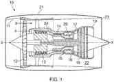
- a ducted fan gas turbine engine is generally indicated at 10 and has a principal and rotational axis X-X.
- the engine comprises, in axial flow series, an air intake 11, a propulsive fan 12, an intermediate pressure compressor 13, a high-pressure compressor 14, combustion equipment 15, a high-pressure turbine 16, an intermediate pressure turbine 17, a low-pressure turbine 18 and a core engine exhaust nozzle 19.
- a nacelle 21 generally surrounds the engine 10 and defines the intake 11, a bypass duct 22 and a bypass exhaust nozzle 23.
- air entering the intake 11 is accelerated by the fan 12 to produce two air flows: a first air flow A into the intermediate-pressure compressor 13 and a second airflow B which passes through the bypass duct 22 to provide propulsive thrust.
- the intermediate-pressure compressor 13 compresses the air flow A directed into it before delivering that air to the high-pressure compressor 14 where further compression takes place.
- the compressed air exhausted from the high-pressure compressor 14 is directed into the combustion equipment 15 where it is mixed with fuel and the mixture combusted.
- the resultant hot combustion products then expand through, and thereby drive the high, intermediate and low-pressure turbines 16, 17, 18 before being exhausted through the nozzle 19 to provide additional propulsive thrust.
- the high, intermediate and low-pressure turbines respectively drive the high and intermediate-pressure compressors 14, 13 and the fan 12 by suitable interconnecting shafts.
- gas turbine engines to which the present disclosure may be applied may have alternative configurations.
- such engines may have an alternative number of interconnecting shafts (e.g. two) and/or an alternative number of compressors and/or turbines.
- the engine may comprise a gearbox provided in the drive train from a turbine to a compressor and/or fan.
- FIG. 2 shows schematically more detail of the intermediate-pressure (IP) compressor 13 and the high-pressure (HP) compressor 14.
- IP intermediate-pressure
- HP high-pressure
- the IP and the HP spool are operatively connected by a permanent magnet electrical machine that transfers power from one of the spools to the other (typically from the faster to the slower).
- This machine has a first (HP) rotor 28 which is connected to the front compressor disc of the HP compressor 14 to rotate with HP spool, and a second (IP) rotor 30 which is connected to the rear compressor disc of the IP compressor 13 to rotate with IP spool.
- the HP and IP rotors are located inwards of the gas annulus 31 for the air flow A.
- the HP rotor 28 supports a circumferential row of permanent magnets
- the IP rotor 30 supports a circumferential row of teeth carrying a row of coils.
- the teeth provide paths for a magnetic flux produced by the permanent magnets, thereby electromagnetically linking the permanent magnets and the coils when the HP rotor rotates relative to the IP rotor so that the coils set up an opposing magnetic flux to transmit torque between the spools.
- the number of active coils can be switched by switching means 32 to control the amount of torque transmission and hence power transfer between the spools.
- the electrical current in the coils generates heat that has to be dissipated, the overall losses involved in the power transfer between the spools can be less than that involved in bleeding compressor air to adjust engine performance.
- the power transferred between the spools can be used to manage compressor behaviour, e.g. to selectively increase a spool's speed to prevent stall and or surge of the compressor combination.
- FIG. 3 shows schematically more detail of the intermediate-pressure (IP) compressor 13 and the high-pressure (HP) compressor 14 having a variant electrical machine for transferring power from one of the spools to the other.
- IP intermediate-pressure
- HP high-pressure
- the machine is split into two parts, namely a driven part and a driver part, each having a respective rotor and stator, with power transfer between the spools being mediated by electrical connection between the coils of the two parts.
- This arrangement can more easily accommodate co-rotating spools. It also allows some of the power to be tapped off to be used elsewhere in the engine and/or allows power to be fed into either or both of the spools. For example, power can be fed in to assist in starting the engine, i.e. to drive the spools. That power can be applied from an external power source in a predefined and controlled way to each spool.
- the machine has an HP rotor 128 which is connected to the front compressor disc of the HP compressor 14 to rotate with the HP spool, and an HP stator 129.
- the HP rotor supports a circumferential row of permanent magnets
- the HP stator supports a circumferential row of teeth carrying a row of coils.
- the machine also has an IP rotor 130 which is connected to the rear compressor disc of the IP compressor 13 to rotate with the IP spool, and an IP stator 131.
- the IP rotor supports another circumferential row of permanent magnets
- the IP stator supports a circumferential row of teeth carrying another row of coils.
- One of the rotor/stator pairs forms the driver part of the electrical machine, and the other of the rotor/stator pairs forms the driven part. These roles are reversible.
- the teeth of the driver part provide paths for a magnetic flux produced by the permanent magnets of the driver part.
- the induced voltage is then applied to the coils of the driven part, which sets up another magnetic flux opposing the magnetic flux produced by the permanent magnets of the rotor of the driven part. In this way torque is transmitted between the spools, and hence power transferred.
- Each of the driver part and the driven part can have respective switching means 132 to switch the number of active coils and hence control the amount of torque transmission and power transfer.
- the spools can alternatively be operatively connected by an electrical machine in which the magnets are formed by energised coils.
Landscapes
- Engineering & Computer Science (AREA)
- Chemical & Material Sciences (AREA)
- Combustion & Propulsion (AREA)
- Mechanical Engineering (AREA)
- General Engineering & Computer Science (AREA)
- Power Engineering (AREA)
- Permanent Magnet Type Synchronous Machine (AREA)
Applications Claiming Priority (1)
| Application Number | Priority Date | Filing Date | Title |
|---|---|---|---|
| GB1718328.6A GB2568093A (en) | 2017-11-06 | 2017-11-06 | Multi-shaft gas turbine engine |
Publications (1)
| Publication Number | Publication Date |
|---|---|
| EP3480433A1 true EP3480433A1 (de) | 2019-05-08 |
Family
ID=60664839
Family Applications (1)
| Application Number | Title | Priority Date | Filing Date |
|---|---|---|---|
| EP18202879.5A Withdrawn EP3480433A1 (de) | 2017-11-06 | 2018-10-26 | Mehrwellengasturbinentriebwerk |
Country Status (3)
| Country | Link |
|---|---|
| US (1) | US20190136768A1 (de) |
| EP (1) | EP3480433A1 (de) |
| GB (1) | GB2568093A (de) |
Cited By (3)
| Publication number | Priority date | Publication date | Assignee | Title |
|---|---|---|---|---|
| EP3767090A1 (de) * | 2019-07-15 | 2021-01-20 | Raytheon Technologies Corporation | Steuerung der betriebsfähigkeit eines kompressors für einen hybriden elektrischen antrieb |
| BE1027469B1 (fr) * | 2019-08-01 | 2021-03-03 | Safran Aero Boosters Sa | Architecture de turbomachine avec booster accéléré |
| EP3960997A1 (de) * | 2020-08-31 | 2022-03-02 | General Electric Company | Abschaltung und wiederanlassen eines hybrid-elektrischen triebwerks während des flugs |
Families Citing this family (13)
| Publication number | Priority date | Publication date | Assignee | Title |
|---|---|---|---|---|
| US10644630B2 (en) * | 2017-11-28 | 2020-05-05 | General Electric Company | Turbomachine with an electric machine assembly and method for operation |
| US12092038B2 (en) | 2019-08-13 | 2024-09-17 | Rtx Corporation | Rotor dynamics accommodation using electrical power assist |
| US10934880B1 (en) * | 2019-09-04 | 2021-03-02 | The Boeing Company | Electrical generation from turbine engines |
| US11362567B2 (en) | 2020-01-16 | 2022-06-14 | The Boeing Company | Electrical power generation from turbine engines |
| US11739694B2 (en) * | 2020-04-15 | 2023-08-29 | General Electric Company | Embedded electric motor assembly |
| US11193426B2 (en) | 2020-04-16 | 2021-12-07 | The Boeing Company | Electrically geared turbofan |
| US12031479B2 (en) * | 2020-08-31 | 2024-07-09 | General Electric Company | Hybrid electric propulsion system load share |
| KR20220082733A (ko) | 2020-12-10 | 2022-06-17 | 더 보잉 컴파니 | 다이렉트 드라이브 전기적-기어식 터보팬 |
| US11845388B2 (en) | 2021-05-20 | 2023-12-19 | General Electric Company | AC electrical power system for a vehicle |
| US12459659B2 (en) | 2022-03-07 | 2025-11-04 | General Electric Company | Method and apparatus for controlling electrical machines operating with a turbine engine |
| US12480449B2 (en) | 2022-08-22 | 2025-11-25 | General Electric Company | Propulsion system including an electric machine for starting a gas turbine engine |
| US12006880B2 (en) | 2022-09-12 | 2024-06-11 | General Electric Company | High bandwidth control of turbofan/turboprop thrust response using embedded electric machines |
| US20250283435A1 (en) * | 2024-03-06 | 2025-09-11 | General Electric Company | Power transfer system for a gas turbine engine |
Citations (4)
| Publication number | Priority date | Publication date | Assignee | Title |
|---|---|---|---|---|
| WO1995002120A1 (en) * | 1993-07-06 | 1995-01-19 | Rolls-Royce Plc | Shaft power transfer in gas turbine engines |
| US6776002B1 (en) * | 2003-04-25 | 2004-08-17 | Northrop Grumman Corporation | Magnetically coupled integrated power and cooling unit |
| EP2660440A2 (de) * | 2012-05-03 | 2013-11-06 | Rolls-Royce plc | Elektromagnetisches Kupplungssystem |
| US20140245748A1 (en) * | 2012-11-20 | 2014-09-04 | Honeywell International Inc. | Gas turbine engine optimization by electric power transfer |
Family Cites Families (2)
| Publication number | Priority date | Publication date | Assignee | Title |
|---|---|---|---|---|
| US7788898B2 (en) * | 2006-12-06 | 2010-09-07 | General Electric Company | Variable coupling of turbofan engine spools via open differential gear set or simple planetary gear set for improved power extraction and engine operability, with torque coupling for added flexibility |
| US7791235B2 (en) * | 2006-12-22 | 2010-09-07 | General Electric Company | Variable magnetic coupling of rotating machinery |
-
2017
- 2017-11-06 GB GB1718328.6A patent/GB2568093A/en not_active Withdrawn
-
2018
- 2018-10-26 EP EP18202879.5A patent/EP3480433A1/de not_active Withdrawn
- 2018-10-26 US US16/171,910 patent/US20190136768A1/en not_active Abandoned
Patent Citations (4)
| Publication number | Priority date | Publication date | Assignee | Title |
|---|---|---|---|---|
| WO1995002120A1 (en) * | 1993-07-06 | 1995-01-19 | Rolls-Royce Plc | Shaft power transfer in gas turbine engines |
| US6776002B1 (en) * | 2003-04-25 | 2004-08-17 | Northrop Grumman Corporation | Magnetically coupled integrated power and cooling unit |
| EP2660440A2 (de) * | 2012-05-03 | 2013-11-06 | Rolls-Royce plc | Elektromagnetisches Kupplungssystem |
| US20140245748A1 (en) * | 2012-11-20 | 2014-09-04 | Honeywell International Inc. | Gas turbine engine optimization by electric power transfer |
Cited By (5)
| Publication number | Priority date | Publication date | Assignee | Title |
|---|---|---|---|---|
| EP3767090A1 (de) * | 2019-07-15 | 2021-01-20 | Raytheon Technologies Corporation | Steuerung der betriebsfähigkeit eines kompressors für einen hybriden elektrischen antrieb |
| US11261751B2 (en) | 2019-07-15 | 2022-03-01 | Raytheon Technologies Corporation | Compressor operability control for hybrid electric propulsion |
| EP3767090B1 (de) | 2019-07-15 | 2023-02-15 | Raytheon Technologies Corporation | Steuerung der betriebsfähigkeit eines kompressors für einen hybriden elektrischen antrieb |
| BE1027469B1 (fr) * | 2019-08-01 | 2021-03-03 | Safran Aero Boosters Sa | Architecture de turbomachine avec booster accéléré |
| EP3960997A1 (de) * | 2020-08-31 | 2022-03-02 | General Electric Company | Abschaltung und wiederanlassen eines hybrid-elektrischen triebwerks während des flugs |
Also Published As
| Publication number | Publication date |
|---|---|
| GB201718328D0 (en) | 2017-12-20 |
| US20190136768A1 (en) | 2019-05-09 |
| GB2568093A (en) | 2019-05-08 |
Similar Documents
| Publication | Publication Date | Title |
|---|---|---|
| US20190136768A1 (en) | Multi-shaft gas turbine engine | |
| JP7026989B2 (ja) | ハイブリッド電気駆動システム | |
| EP3763929B1 (de) | Elektrischer generator eines gasturbinentriebwerks | |
| EP2602458B1 (de) | Steuerungsverfahren und -system mehrerer Wellenleistungstriebwerke für Hubschrauber | |
| EP1936150B1 (de) | Hochgeschwindigkeitsgeneratoren mit hoher Polzahl | |
| US7514810B2 (en) | Electric power generation using power turbine aft of LPT | |
| CA2466756C (en) | Differential geared turbine engine with torque modulation capability | |
| EP3763931A1 (de) | Elektrischer generator eines gasturbinentriebwerks | |
| US8198744B2 (en) | Integrated boost cavity ring generator for turbofan and turboshaft engines | |
| JP5188169B2 (ja) | 回転機械の可変磁気結合 | |
| US9328667B2 (en) | Systems and methods for changing a speed of a compressor boost stage in a gas turbine | |
| EP2128389A2 (de) | Gasturbinenmotoranordnung | |
| EP3904657B1 (de) | Hybride verstärkung von hochdruckwellenbetrieb über niederdruckwellenleistungsextraktion und antrieb von einem differenzialgetriebegenerator | |
| JP2008207799A (ja) | 船舶推進システム及びそれを作動させる方法 | |
| US20160130970A1 (en) | Jet engine assembly and method for generating electricity | |
| EP1614880B1 (de) | Gasturbinentriebwerk | |
| EP3460966A1 (de) | Elektrische permanentmagnetmaschine | |
| EP3416279A1 (de) | Elektrische maschine | |
| CN110273757B (zh) | 电力发电机系统 |
Legal Events
| Date | Code | Title | Description |
|---|---|---|---|
| PUAI | Public reference made under article 153(3) epc to a published international application that has entered the european phase |
Free format text: ORIGINAL CODE: 0009012 |
|
| STAA | Information on the status of an ep patent application or granted ep patent |
Free format text: STATUS: THE APPLICATION HAS BEEN PUBLISHED |
|
| AK | Designated contracting states |
Kind code of ref document: A1 Designated state(s): AL AT BE BG CH CY CZ DE DK EE ES FI FR GB GR HR HU IE IS IT LI LT LU LV MC MK MT NL NO PL PT RO RS SE SI SK SM TR |
|
| AX | Request for extension of the european patent |
Extension state: BA ME |
|
| RAP1 | Party data changed (applicant data changed or rights of an application transferred) |
Owner name: ROLLS-ROYCE PLC |
|
| STAA | Information on the status of an ep patent application or granted ep patent |
Free format text: STATUS: THE APPLICATION IS DEEMED TO BE WITHDRAWN |
|
| 18D | Application deemed to be withdrawn |
Effective date: 20191109 |