EP3480100A2 - Method for play compensation of a drive unit, control device and vehicle with said control device - Google Patents
Method for play compensation of a drive unit, control device and vehicle with said control device Download PDFInfo
- Publication number
- EP3480100A2 EP3480100A2 EP18193694.9A EP18193694A EP3480100A2 EP 3480100 A2 EP3480100 A2 EP 3480100A2 EP 18193694 A EP18193694 A EP 18193694A EP 3480100 A2 EP3480100 A2 EP 3480100A2
- Authority
- EP
- European Patent Office
- Prior art keywords
- torque
- vehicle
- electric motor
- detected
- rotation
- Prior art date
- Legal status (The legal status is an assumption and is not a legal conclusion. Google has not performed a legal analysis and makes no representation as to the accuracy of the status listed.)
- Granted
Links
Images


Classifications
-
- B—PERFORMING OPERATIONS; TRANSPORTING
- B62—LAND VEHICLES FOR TRAVELLING OTHERWISE THAN ON RAILS
- B62M—RIDER PROPULSION OF WHEELED VEHICLES OR SLEDGES; POWERED PROPULSION OF SLEDGES OR SINGLE-TRACK CYCLES; TRANSMISSIONS SPECIALLY ADAPTED FOR SUCH VEHICLES
- B62M6/00—Rider propulsion of wheeled vehicles with additional source of power, e.g. combustion engine or electric motor
- B62M6/40—Rider propelled cycles with auxiliary electric motor
- B62M6/45—Control or actuating devices therefor
-
- B—PERFORMING OPERATIONS; TRANSPORTING
- B60—VEHICLES IN GENERAL
- B60L—PROPULSION OF ELECTRICALLY-PROPELLED VEHICLES; SUPPLYING ELECTRIC POWER FOR AUXILIARY EQUIPMENT OF ELECTRICALLY-PROPELLED VEHICLES; ELECTRODYNAMIC BRAKE SYSTEMS FOR VEHICLES IN GENERAL; MAGNETIC SUSPENSION OR LEVITATION FOR VEHICLES; MONITORING OPERATING VARIABLES OF ELECTRICALLY-PROPELLED VEHICLES; ELECTRIC SAFETY DEVICES FOR ELECTRICALLY-PROPELLED VEHICLES
- B60L15/00—Methods, circuits, or devices for controlling the traction-motor speed of electrically-propelled vehicles
- B60L15/20—Methods, circuits, or devices for controlling the traction-motor speed of electrically-propelled vehicles for control of the vehicle or its driving motor to achieve a desired performance, e.g. speed, torque, programmed variation of speed
- B60L15/2045—Methods, circuits, or devices for controlling the traction-motor speed of electrically-propelled vehicles for control of the vehicle or its driving motor to achieve a desired performance, e.g. speed, torque, programmed variation of speed for optimising the use of energy
-
- B—PERFORMING OPERATIONS; TRANSPORTING
- B60—VEHICLES IN GENERAL
- B60L—PROPULSION OF ELECTRICALLY-PROPELLED VEHICLES; SUPPLYING ELECTRIC POWER FOR AUXILIARY EQUIPMENT OF ELECTRICALLY-PROPELLED VEHICLES; ELECTRODYNAMIC BRAKE SYSTEMS FOR VEHICLES IN GENERAL; MAGNETIC SUSPENSION OR LEVITATION FOR VEHICLES; MONITORING OPERATING VARIABLES OF ELECTRICALLY-PROPELLED VEHICLES; ELECTRIC SAFETY DEVICES FOR ELECTRICALLY-PROPELLED VEHICLES
- B60L50/00—Electric propulsion with power supplied within the vehicle
- B60L50/20—Electric propulsion with power supplied within the vehicle using propulsion power generated by humans or animals
-
- B—PERFORMING OPERATIONS; TRANSPORTING
- B62—LAND VEHICLES FOR TRAVELLING OTHERWISE THAN ON RAILS
- B62M—RIDER PROPULSION OF WHEELED VEHICLES OR SLEDGES; POWERED PROPULSION OF SLEDGES OR SINGLE-TRACK CYCLES; TRANSMISSIONS SPECIALLY ADAPTED FOR SUCH VEHICLES
- B62M6/00—Rider propulsion of wheeled vehicles with additional source of power, e.g. combustion engine or electric motor
- B62M6/40—Rider propelled cycles with auxiliary electric motor
- B62M6/55—Rider propelled cycles with auxiliary electric motor power-driven at crank shafts parts
-
- G—PHYSICS
- G01—MEASURING; TESTING
- G01L—MEASURING FORCE, STRESS, TORQUE, WORK, MECHANICAL POWER, MECHANICAL EFFICIENCY, OR FLUID PRESSURE
- G01L25/00—Testing or calibrating of apparatus for measuring force, torque, work, mechanical power, or mechanical efficiency
- G01L25/003—Testing or calibrating of apparatus for measuring force, torque, work, mechanical power, or mechanical efficiency for measuring torque
-
- G—PHYSICS
- G01—MEASURING; TESTING
- G01L—MEASURING FORCE, STRESS, TORQUE, WORK, MECHANICAL POWER, MECHANICAL EFFICIENCY, OR FLUID PRESSURE
- G01L5/00—Apparatus for, or methods of, measuring force, work, mechanical power, or torque, specially adapted for specific purposes
- G01L5/13—Apparatus for, or methods of, measuring force, work, mechanical power, or torque, specially adapted for specific purposes for measuring the tractive or propulsive power of vehicles
-
- B—PERFORMING OPERATIONS; TRANSPORTING
- B60—VEHICLES IN GENERAL
- B60L—PROPULSION OF ELECTRICALLY-PROPELLED VEHICLES; SUPPLYING ELECTRIC POWER FOR AUXILIARY EQUIPMENT OF ELECTRICALLY-PROPELLED VEHICLES; ELECTRODYNAMIC BRAKE SYSTEMS FOR VEHICLES IN GENERAL; MAGNETIC SUSPENSION OR LEVITATION FOR VEHICLES; MONITORING OPERATING VARIABLES OF ELECTRICALLY-PROPELLED VEHICLES; ELECTRIC SAFETY DEVICES FOR ELECTRICALLY-PROPELLED VEHICLES
- B60L2200/00—Type of vehicles
- B60L2200/12—Bikes
-
- B—PERFORMING OPERATIONS; TRANSPORTING
- B60—VEHICLES IN GENERAL
- B60L—PROPULSION OF ELECTRICALLY-PROPELLED VEHICLES; SUPPLYING ELECTRIC POWER FOR AUXILIARY EQUIPMENT OF ELECTRICALLY-PROPELLED VEHICLES; ELECTRODYNAMIC BRAKE SYSTEMS FOR VEHICLES IN GENERAL; MAGNETIC SUSPENSION OR LEVITATION FOR VEHICLES; MONITORING OPERATING VARIABLES OF ELECTRICALLY-PROPELLED VEHICLES; ELECTRIC SAFETY DEVICES FOR ELECTRICALLY-PROPELLED VEHICLES
- B60L2240/00—Control parameters of input or output; Target parameters
- B60L2240/40—Drive Train control parameters
- B60L2240/42—Drive Train control parameters related to electric machines
- B60L2240/423—Torque
-
- Y—GENERAL TAGGING OF NEW TECHNOLOGICAL DEVELOPMENTS; GENERAL TAGGING OF CROSS-SECTIONAL TECHNOLOGIES SPANNING OVER SEVERAL SECTIONS OF THE IPC; TECHNICAL SUBJECTS COVERED BY FORMER USPC CROSS-REFERENCE ART COLLECTIONS [XRACs] AND DIGESTS
- Y02—TECHNOLOGIES OR APPLICATIONS FOR MITIGATION OR ADAPTATION AGAINST CLIMATE CHANGE
- Y02T—CLIMATE CHANGE MITIGATION TECHNOLOGIES RELATED TO TRANSPORTATION
- Y02T10/00—Road transport of goods or passengers
- Y02T10/60—Other road transportation technologies with climate change mitigation effect
- Y02T10/64—Electric machine technologies in electromobility
-
- Y—GENERAL TAGGING OF NEW TECHNOLOGICAL DEVELOPMENTS; GENERAL TAGGING OF CROSS-SECTIONAL TECHNOLOGIES SPANNING OVER SEVERAL SECTIONS OF THE IPC; TECHNICAL SUBJECTS COVERED BY FORMER USPC CROSS-REFERENCE ART COLLECTIONS [XRACs] AND DIGESTS
- Y02—TECHNOLOGIES OR APPLICATIONS FOR MITIGATION OR ADAPTATION AGAINST CLIMATE CHANGE
- Y02T—CLIMATE CHANGE MITIGATION TECHNOLOGIES RELATED TO TRANSPORTATION
- Y02T10/00—Road transport of goods or passengers
- Y02T10/60—Other road transportation technologies with climate change mitigation effect
- Y02T10/72—Electric energy management in electromobility
Definitions
- the present invention relates to a method for free-wheeling compensation of a drive unit, a control unit for carrying out the method and a vehicle, comprising the drive unit and this control unit, wherein the vehicle is in particular an electric bicycle.
- the crankshaft is typically connected to two pedals. Cyclists pedal, for example, backwards to align the pedals in a desired position when the bicycle is stationary.
- Electric bicycles may have a drive unit on the crankshaft, wherein the drive unit further comprises, for example, a crankshaft and an electric motor.
- the rotatable components each have a positive direction of rotation and a negative direction of rotation, wherein the positive direction of rotation is adapted to drive a drive wheel of the vehicle for forward travel.
- the crankshaft can be rotatably connected to the electric motor by means of a driver's freewheel with respect to the negative direction of rotation with the electric motor or without the freewheel clutch. Without the freewheel, the drive unit is lighter in weight and compact in space.
- the production of the drive unit without driver freewheel is cheaper.
- a driver In a rotationally fixed connection between the crankshaft and the electric motor, a driver must overcome the drag torque of the electric motor, as well as the friction losses in the gearbox to align the pedals when pedaling in a negative direction.
- a non-rotatable connection between the crankshaft and the electric motor in the rearward sliding of the electric bicycle or when moving the rotatable components of a drive unit in the negative direction makes the drag torque or a Cogging torque of the electric motor by a jerky or jerky rotation of the crankshaft or the pedals noticeable.
- the drag torque of the motor is essentially composed of cogging torque, losses in the bearing of the rotor shaft and iron losses in the engine.
- the object of the present invention is to reduce unwanted effects of a rotationally fixed connection in negative rotational direction between the crankshaft and the electric motor.
- the invention relates to a method for free-wheeling compensation for a vehicle having a drive unit, in particular an electric bicycle.
- the drive unit has at least one rotatable component.
- the rotatable component may have a positive direction of rotation or a negative direction of rotation, wherein the positive direction of rotation is adapted to drive a drive wheel of the vehicle for forward travel.
- the inventive method has a detection of the negative direction of rotation of a rotatable component of the drive unit. Subsequently, a directed in the negative direction of rotation motor torque is generated by means of an electric motor of the drive unit at a detected negative rotational direction.
- the generated motor torque is less than a drag torque of the electric motor and configured to reduce a force of a driver of the vehicle to rotate the electric motor.
- the method thus advantageously reduces the pedaling force required by the driver when aligning the pedals in the negative direction of rotation or the force required by the driver for the rearward sliding of the electric bicycle since the electric motor is actuated and thus the drag torque of the electric motor is not complete must be overcome by the driver.
- the generated engine torque is independent of the speed and / or a torque applied by the driver or constant. As a result, the generated engine torque is difficult for the driver to perceive. It therefore results in pedaling in the negative direction of rotation advantageously the impression of a freewheel between the crankshaft and the electric motor.
- an angular position and / or a rotational speed and / or a torque of a rotatable component of the drive unit is detected.
- the negative direction of rotation is detected as a function of the detected angular position and / or the detected rotational speed and / or the detected torque.
- the detection takes place by means of the rotor position sensors of the electric motor and / or an angular momentum transmitter (for example optical, magnetic, mechanical, etc.) and / or a sensor for detecting the driver torque.
- the generation of the engine torque takes place as a function of the detected angular position and / or the detected rotational speed and / or the detected torque.
- a speed-dependent drag torque or cogging torque of the electric motor for generating the motor torque can be taken into account, so that the generated motor torque at detected negative direction of rotation is reliably smaller than the drag torque.
- the detection of an acceleration of the vehicle takes place in the direction of the longitudinal axis of the vehicle.
- the generation of the engine torque is additionally performed in this continuation depending on the detected acceleration of the vehicle.
- a calibration method for determining the drag torque of the electric motor of the Drive unit performed.
- the generation of the engine torque is then additionally in dependence on the determined drag torque.
- This continuation has the advantage that due to manufacturing tolerances for each electric motor varying drag torque and / or changing with increasing life drag torque is determined.
- An accurately determined drag torque advantageously allows a barely perceptible implementation of the method for freewheel compensation or increases the ride comfort of the driver of the vehicle with the drive unit.
- the calibration method for determining a drag torque comprises generating a calibration torque by means of the electric motor.
- the calibration torque is greater than the drag torque of the electric motor.
- a detection of a rotational speed of the electric motor is a detection of a rotational speed of the electric motor.
- the calibration torque is adjusted as a function of the detected rotational speed for setting a predetermined rotational speed, wherein the predetermined rotational speed is in particular less than 5 revolutions per minute.
- the determination of the drag torque of the electric motor takes place as a function of the adjusted calibration torque.
- a detection of a speed of the vehicle is performed.
- the generation of the calibration torque is additionally effected as a function of the detected speed, the calibration torque being generated in particular when the vehicle is at a standstill.
- the calibration method is advantageously carried out only at low speeds or at standstill of the vehicle.
- the invention also relates to the control device for carrying out the method.
- the control unit detects the negative direction of rotation of a rotatable component of the drive unit by means of at least one sensor. Subsequently, the control unit generates a control signal.
- the control signal is set up to control the electric motor of the drive unit to generate the motor torque directed in the negative direction of rotation in the case of a detected negative direction of rotation.
- the generated engine torque is less than a drag torque of the electric motor and thus configured to reduce a force of a driver of the vehicle for rotation of the electric motor.
- the at least one sensor for detecting the negative direction of rotation is an angular position sensor of the rotor of the electric motor and / or a rotational speed sensor and / or a torque sensor.
- control unit generates the control signal as a function of the detected angular position and / or the rotational speed and / or the detected torque.
- control unit detects a speed of the vehicle by means of a speed sensor.
- control unit additionally generates the control signal as a function of the detected speed of the vehicle.
- the control device preferably also detects an acceleration of the vehicle in the direction of the longitudinal axis of the vehicle by means of an acceleration sensor.
- the control signal is additionally generated in this embodiment as a function of the detected acceleration of the vehicle.
- the control unit can optionally generate a calibration control signal, in particular at fixed time intervals.
- the calibration control signal is adapted to drive the electric motor to generate a calibration torque, wherein the calibration torque is greater than the drag torque of the electric motor.
- a rotational speed of the electric motor is detected and the calibration control signal is adjusted as a function of the detected rotational speed.
- the adjustment of the calibration control signal is carried out to set a predetermined rotational speed, wherein the predetermined rotational speed is in particular less than five revolutions per minute.
- the control unit determines the drag torque of the electric motor as a function of the adjusted calibration torque.
- control unit detects the speed of the vehicle by means of the speed sensor and that Calibration control signal additionally generated in dependence on the detected speed.
- control unit only generates the calibration control signal when the vehicle is at a standstill.
- the invention also relates to the vehicle, in particular the electric bicycle, with the drive unit and the control unit.
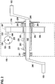
- FIG. 1 an electric bicycle 100 is shown. It can be moved in the direction of a longitudinal axis 101 of the electric bicycle 100 in the direction of travel forward or, for example, by sliding backwards.
- the rear wheel or the driving wheel 104 and the rotatable components 102, 210 and 151 of a drive unit 150 of the electric bicycle 150 may each have a positive direction of rotation when the bicycle 100 moves forward or a negative direction of rotation when the bicycle 100 is moved in the rearward direction.
- the negative rotational direction of the wheels 104 of the electric bicycle 100 and the two pedals 103 of the drive unit 150 is in FIG. 1 indicated by arrows.
- the electric bicycle 100 is motor-driven by means of the two pedals 103 by the driver and / or by means of an electric motor 151 of the drive unit 150. Both the pedals 103 and the electric motor 151 are rotationally fixed in the negative direction of rotation with a crankshaft 102 of the Drive unit 150 connected. Accordingly, between the crankshaft 102 and the electric motor 151 and / or between the driven chain blade 220 and the electric motor 151, there is no freewheel for interrupting transmission of a negative direction driver torque M F from the crankshaft 102 to the electric motor 151 and / or a sliding torque thereof Output chain 220 arranged on the electric motor 151.
- the pedals 103 and the electric motor 151 consequently rotate in the case of pedaling directed in the negative direction of rotation or of the electric bicycle 100 in the rearward direction.
- a drive unit 150 for an electric bicycle 100 is shown.
- the crankshaft 102 is rotatably mounted in the drive unit 150 by means of two bearings 201 and 204.
- the crankshaft 102 is further rotatably connected in this example with a hollow shaft 202, wherein the hollow shaft 202 is adapted to be rotated by the driver torque M F.
- the rotation of the hollow shaft 202 is detected by means of a sensor 235, whereby the driver torque M F is detected or measured.
- a gear 210 is arranged with two gears 206 and 207, wherein between the gear 210 and the gear 206 and the hollow shaft 202, a motor freewheel 203 is arranged.
- the gear 210 rotatably connects the electric motor 151 and the hollow shaft 202 or the crankshaft 102 in the negative direction of rotation with each other.
- the engine freewheel 203 is configured to interrupt a transmission of engine torque of the electric motor 151 in the positive direction when driving in the forward direction, the driver torque M F in the positive direction stronger than the engine torque M M in the positive direction of rotation or the speed of the crankshaft 102 in positive Direction of rotation is faster than the rotational speed of the rotor shaft 208 in the positive direction of rotation.
- the hollow shaft 202 is further connected to an output chain plate 220.
- the output chain plate 220 is configured to transmit the total torque of the drive unit 150 to the drive wheel 104 of the electric bicycle 100 by means of a chain or a belt.
- the total torque represents the sum of the driver torque M F and the engine torque M M.
- the drive unit 150 in this embodiment no freewheel for interrupting a transmission of a rotation in the negative direction of rotation, that is, the crankshaft 102, the output link 220 and the electric motor 151 are rotatably connected to each other in the negative direction of rotation.
- the negative direction of rotation or the angular position of the rotor shaft 208 can be detected by means of a sensor or a plurality of sensors 230 in the electric motor 151 or on the rotor shaft 208 by means of the rotor position sensors 230 and / or a rotational speed sensor. Additionally or alternatively, at least one rotational speed or cadence sensor 231 and / or one may be used to detect the negative direction of rotation Rotational speed sensor on the crankshaft 102 or the hollow shaft 202 or on one of the cranks 240 or on a wheel axle, for example, on the wheel axle of the rear wheel 104 may be arranged. Furthermore, the detection of the direction of rotation can alternatively or additionally take place by means of the torque sensor 235.
- a freewheel in the negative direction of rotation between the output chain plate 220 and the hollow shaft 202 or between the output chain plate 220 and the gear 210 and / or the crankshaft 102 and / or in the hub or axle of the drive wheel 104.
- the drag torque M B of the electric motor 151 of the drive unit 150 must also be overcome because of the connection between the crankshaft 102 and the electric motor 151, which is rotationally fixed in the negative direction of rotation. Furthermore, when the electric bicycle 100 is pushed backwards, the torque directed in the negative direction of rotation is transmitted to the drive unit 150, in particular to the pedals 103 and the electric motor 151. Accordingly, without the present invention, when pushing backward, a pushing force greater than the drag torque M B of the electric motor 151 needs to be generated. Furthermore, due to the cogging torque of the electric motor 151 in the backward sliding without the present invention, the pedals 103 undesirably turn jerkily about the crankshaft 102.
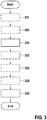
- FIG. 3 The method starts with a detection 310 of the negative direction of rotation of a rotatable component 102, 210, 151 of the drive unit 150.
- a detection 305 of an angular position and / or a rotational speed and / or a torque of a rotatable component 102, 210, 151 of the drive unit 150 performed and the negative direction of rotation in dependence on the angular position and / or the torque is detected or determined.
- the angular position and / or the rotational speed of the rotor shaft 208 of the electric motor 151, the gears 206 and 207 of the transmission 210 and / or the crankshaft 102 are detected.
- a motor torque M M directed in a negative direction of rotation or an engine force directed in a negative direction of rotation is generated on the rotor of the electric motor 151 or the rotor shaft 208 by means of the electric motor 151.
- the generated motor torque M M is smaller than a drag torque M B of the electric motor 151. Accordingly, the generated motor torque M M reduces the force required for the rotation of the rotor or the rotor shaft 208 of the driver.
- the generation 330 of the engine torque M M takes place optionally as a function of the detected rotational speed and / or the detected torque and / or a detected rotational speed, which can be determined from the detected angular position.
- the motor torque M M does not exceed a limit value, wherein the limit value represents, for example, the drag torque M B or an approximate value for the drag torque.
- the limit value is, for example, smaller by a factor of 0.60 to 0.95 than the drag torque M B.
- the generation 330 of the motor torque M M M in the negative direction of rotation optionally optionally additionally takes place as a function of the drag torque M B , which can be regularly updated or determined and stored, for example, in a memory unit 402 of the control unit 400, see also explanations below.
- the engine torque M M is smaller than the drag torque M B and therefore too small to independently generate a drive of the electric motor 151.
- the motor torque M M generated by the control of the electric motor 151 advantageously results in a reduced power requirement for the driver when pedaling in the negative direction of rotation, for example, for alignment or positioning of the pedals 103.
- the generated engine torque M M is preferably constant, that is, regardless of the rotational speed of the crankshaft 102 or the rotational speed of the crankshaft 102 or the driver torque on the pedals 103rd
- a detection 325 of the speed of the vehicle 100 takes place in the direction of the longitudinal axis of the vehicle 100.
- Generation 330 of the motor torque M M directed in the negative direction of rotation then additionally takes place as a function of the detected speed. Due to the additional consideration of the Speed is the generation of the negative direction of rotation directed engine torque M M, for example, only at standstill of the vehicle 100 and / or at a speed less than a speed threshold, for example, 10 km / h performed.
- a detection 326 of an acceleration 100 of the vehicle 100 takes place in the direction of the longitudinal axis of the vehicle 100.
- Generation 330 of the motor torque M M which is directed in the negative direction of rotation, then takes place additionally as a function of the detected acceleration. Due to the additional consideration of the acceleration, the generation of the negative direction of rotation directed engine torque M M, for example, carried out only when pushing the vehicle.
- the current drag torque M B is preferably determined by a calibration method.
- the optional first calibration method 301 of the drag torque M B takes place, for example, directly after the assembly of the drive unit 150.
- the optional second calibration method 329 takes place automatically and depending on the detected speed of the electric bicycle 100, preferably during a standstill of the electric bicycle 100 during operation of the electric bicycle 100, for example a traffic light.
- the drag torque M B determined by the first calibration method 301 and / or the second calibration method 329 is stored in a memory 402 of the controller 400.
- the first calibration method 301 and / or the second calibration method 329 of the drag torque M R is effected by controlling the electric motor 151 by means of the control unit 400 for setting a calibration torque as a function of the detected speed, for example only when the vehicle 100 is at rest.
- the generated calibration torque results a rotational speed n K of the electric motor 151 directed in the negative direction of rotation.
- the generated rotational speed n K is preferably small and barely perceptible to a driver.
- the generated calibration torque is therefore greater than the drag torque M B.
- the calibration torque is then adjusted as a function of the detected rotational speed n K until a predetermined rotational speed n K is reached.
- The, in particular average, calibration torque generated for setting the predetermined rotational speed n K is then multiplied to determine the drag torque M B by a constant factor smaller than 1.00, wherein the factor is in particular between 0.10 to 0.98.
- the second calibration method can be performed as an update of the drag torque M B at standstill of the electric bicycle 100, since a slow in negative direction of rotation directed rotation of the drive unit 150 and the electric motor 151 is barely perceptible by the driver.
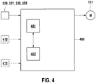
- the control device 400 has a computing unit 401 and a memory unit 402.
- the control unit 400 detects a negative direction of rotation of a rotatable component of the drive unit 150 by means of the sensors 230, 231 and / or 232, for example by means of the rotor position sensors 230.
- the control unit 400 generates a control signal in a negative direction of rotation of the drive unit 150.
- the control signal is set up to drive the electric motor 151 to generate 330 a motor torque M M directed in the negative direction of rotation, the motor torque M M directed in the negative direction of rotation being smaller than the drag torque M B of the electric motor 151.
- the control signal can optionally also be generated as a function of a determination of the drag torque M B or as a function of an update of the drag torque M B. Furthermore, it can optionally be provided that the control device 400 detects a speed v of the electric bicycle 100 in the longitudinal direction of the electric bicycle 100 by means of a speed sensor 410 and / or an acceleration a of the electric bicycle 100 in the longitudinal direction of the electric bicycle 100 by means of an acceleration sensor 411. The control signal is then generated by the control unit 400 as a function of the detected speed v and / or the detected acceleration a.
- control signal is generated only at standstill or at low speeds v of the electric bicycle 100, in particular at a speed of less than 10 km / h or at standstill of the electric bicycle 100, that is to say at a speed of 0 km / h.
- FIG. 12 is a torque and rotational speed chart for pedaling a driver of the electric bicycle 100 in the negative rotational direction.
- the driver initially generates a pedaling force 103 directed in the negative direction of rotation, which results in a driver torque M F directed in the negative direction of rotation, or a negative driver torque M 1 .
- the driver torque M F or M 1 exceeds an adhesion torque M H for overcoming the stoppage of the rotor shaft 208 of the electric motor 151.
- the adhesion torque M H is greater in magnitude than the drag torque M B.
- the driver torque M 1 is therefore at the beginning in terms of magnitude greater than the drag torque M B of the electric motor 151.
- Das Driver torque M 1 results after a time t 1 in a negative rotational speed ni of a shaft in the drive unit 150.
- the generated negative rotational direction is detected in step 310 by means of a sensor 230, 231, 232 and / or 235 during a measuring time period t M.
- the driver torque M F is greater than or equal to the drag torque M B.
- the negative direction of rotation is detected or determined up to a time t 2 .
- a motor torque M M is generated in step 330 at time t 3 .
- This motor torque M M is smaller in magnitude than the drag torque M B of the electric motor 151 and has a negative direction of rotation.
- the generated motor torque M M reduces the driver torque M 3 to be applied by the driver of the electric bicycle 100 to generate the negative speed ni.
- the driver is thus simulated by the motor torque M M generated in step 330, a driver's drive of the drive unit 150, that is, the pedals can be moved by a lower pedaling force of the driver in the negative direction or a lower driver torque M 3 .
Landscapes
- Engineering & Computer Science (AREA)
- Chemical & Material Sciences (AREA)
- Combustion & Propulsion (AREA)
- Transportation (AREA)
- Mechanical Engineering (AREA)
- Physics & Mathematics (AREA)
- General Physics & Mathematics (AREA)
- Power Engineering (AREA)
- Electric Propulsion And Braking For Vehicles (AREA)
Abstract
Verfahren zur Freilaufkompensation für ein Fahrzeug (100) mit einer Antriebseinheit (150), insbesondere ein Elektrofahrrad, wobei die Antriebseinheit (150) mindestens eine drehbare Komponente aufweist, wobei die drehbare Komponente (102, 210, 151) eine positive Drehrichtung oder eine negative Drehrichtung aufweisen kann, wobei die positive Drehrichtung dazu eingerichtet ist, ein Antriebsrad des Fahrzeugs (100) zur Vorwärtsfahrt anzutreiben, wobei das Verfahren die folgenden Schritte aufweist: Erfassung (310) der negativen Drehrichtung einer drehbaren Komponente (102, 210, 151) der Antriebseinheit (150), und Erzeugung (330) eines in negativer Drehrichtung gerichteten Motordrehmoments (MM) mittels eines Elektromotors (151) der Antriebseinheit (150) bei einer erfassten negativen Drehrichtung, wobei das erzeugte Motordrehmoment (MM) kleiner als ein Schleppmoment (MB) des Elektromotors (151) und dazu eingerichtet ist, eine Kraft eines Fahrers des Fahrzeugs (100) zur Drehung des Elektromotors (151) zu reduzieren.

Description
Die vorliegende Erfindung betrifft ein Verfahren zur Freilaufkompensation einer Antriebseinheit, ein Steuergerät zur Durchführung des Verfahrens und ein Fahrzeug, aufweisend die Antriebseinheit und dieses Steuergerät, wobei das Fahrzeug insbesondere ein Elektrofahrrad ist.The present invention relates to a method for free-wheeling compensation of a drive unit, a control unit for carrying out the method and a vehicle, comprising the drive unit and this control unit, wherein the vehicle is in particular an electric bicycle.
Bei Fahrrädern ist die Kurbelwelle typischerweise mit zwei Pedalen verbunden. Fahrradfahrer pedalieren beispielsweise rückwärts um im Stillstand des Fahrrads die Pedale in eine gewünschte Position auszurichten. Elektrofahrräder können eine Antriebseinheit an der Kurbelwelle aufweisen, wobei die Antriebseinheit beispielsweise des Weiteren eine Kurbelwelle und einen Elektromotor umfasst. Die drehbaren Komponenten weisen jeweils eine positive Drehrichtung und eine negative Drehrichtung auf, wobei die positive Drehrichtung dazu eingerichtet ist, ein Antriebsrad des Fahrzeugs zur Vorwärtsfahrt anzutreiben. Die Kurbelwelle kann mittels eines Fahrerfreilaufs bezüglich der negativen Drehrichtung drehbar mit dem Elektromotor oder ohne Fahrerfreilauf drehfest mit dem Elektromotor verbunden sein. Ohne Fahrerfreilauf ist die Antriebseinheit im Gewicht leichter und ihr Bauraum kompakter. Des Weiteren ist die Herstellung der Antriebseinheit ohne Fahrerfreilauf günstiger. Bei einer drehfesten Verbindung zwischen der Kurbelwelle und dem Elektromotor muss ein Fahrer beim Treten bzw. Pedalieren in negativer Drehrichtung das Schleppmoment des Elektromotors, sowie die Reibungsverluste im Getriebe zur Ausrichtung der Pedale überwinden. Des Weiteren macht sich bei einer drehfesten Verbindung zwischen der Kurbelwelle und dem Elektromotor beim rückwärts gerichteten Schieben des Elektrofahrrads beziehungsweise beim Bewegen der drehbaren Komponenten einer Antriebseinheit in negativer Drehrichtung das Schleppmoment beziehungsweise ein Rastmoment des Elektromotors durch eine stoßartige oder ruckartige Drehung der Kurbelwelle beziehungsweise der Pedale bemerkbar. Das Schleppmoment des Motors setzt sich im Wesentlichen zusammen aus Rastmoment, Verlusten in der Lagerung der Rotorwelle und Eisenverlusten im Motor.For bicycles, the crankshaft is typically connected to two pedals. Cyclists pedal, for example, backwards to align the pedals in a desired position when the bicycle is stationary. Electric bicycles may have a drive unit on the crankshaft, wherein the drive unit further comprises, for example, a crankshaft and an electric motor. The rotatable components each have a positive direction of rotation and a negative direction of rotation, wherein the positive direction of rotation is adapted to drive a drive wheel of the vehicle for forward travel. The crankshaft can be rotatably connected to the electric motor by means of a driver's freewheel with respect to the negative direction of rotation with the electric motor or without the freewheel clutch. Without the freewheel, the drive unit is lighter in weight and compact in space. Furthermore, the production of the drive unit without driver freewheel is cheaper. In a rotationally fixed connection between the crankshaft and the electric motor, a driver must overcome the drag torque of the electric motor, as well as the friction losses in the gearbox to align the pedals when pedaling in a negative direction. Furthermore, in a non-rotatable connection between the crankshaft and the electric motor in the rearward sliding of the electric bicycle or when moving the rotatable components of a drive unit in the negative direction makes the drag torque or a Cogging torque of the electric motor by a jerky or jerky rotation of the crankshaft or the pedals noticeable. The drag torque of the motor is essentially composed of cogging torque, losses in the bearing of the rotor shaft and iron losses in the engine.
Die Aufgabe der vorliegenden Erfindung ist es, unerwünschte Effekte einer in negativer Drehrichtung drehfesten Verbindung zwischen der Kurbelwelle und dem Elektromotor zu reduzieren.The object of the present invention is to reduce unwanted effects of a rotationally fixed connection in negative rotational direction between the crankshaft and the electric motor.
Die Erfindung betrifft ein Verfahren zur Freilaufkompensation für ein Fahrzeug mit einer Antriebseinheit, insbesondere ein Elektrofahrrad. Die Antriebseinheit weist mindestens eine drehbare Komponente auf. Die drehbare Komponente kann eine positive Drehrichtung oder eine negative Drehrichtung aufweisen, wobei die positive Drehrichtung dazu eingerichtet ist, ein Antriebsrad des Fahrzeugs zur Vorwärtsfahrt anzutreiben. Das erfindungsgemäße Verfahren weist eine Erfassung der negativen Drehrichtung einer drehbaren Komponente der Antriebseinheit auf. Anschließend wird ein in negativer Drehrichtung gerichtetes Motordrehmoment mittels eines Elektromotors der Antriebseinheit bei einer erfassten negativen Drehrichtung erzeugt. Das erzeugte Motordrehmoment ist kleiner als ein Schleppmoment des Elektromotors und dazu eingerichtet, eine Kraft eines Fahrers des Fahrzeugs zur Drehung des Elektromotors zu reduzieren. Durch das Verfahren wird demnach vorteilhafterweise die durch den Fahrer benötigte Trittkraft auf die Pedale beim Ausrichten der Pedale in negativer Drehrichtung oder die durch den Fahrer benötigte Kraft zum rückwärts gerichteten Schieben des Elektrofahrrads reduziert, da der Elektromotor angesteuert wird und somit das Schleppmoment des Elektromotors nicht vollständig durch den Fahrer überwunden werden muss. Vorteilhafterweise ist das erzeugte Motordrehmoment unabhängig von der Drehzahl und/oder eines durch den Fahrer aufgebrachten Drehmomentes beziehungsweise konstant. Dadurch ist das erzeugte Motordrehmoment nur schwer für den Fahrer wahrnehmbar. Es resultiert demnach beim Pedalieren in negativer Drehrichtung vorteilhafterweise der Eindruck eines Freilaufs zwischen der Kurbelwelle und dem Elektromotor.The invention relates to a method for free-wheeling compensation for a vehicle having a drive unit, in particular an electric bicycle. The drive unit has at least one rotatable component. The rotatable component may have a positive direction of rotation or a negative direction of rotation, wherein the positive direction of rotation is adapted to drive a drive wheel of the vehicle for forward travel. The inventive method has a detection of the negative direction of rotation of a rotatable component of the drive unit. Subsequently, a directed in the negative direction of rotation motor torque is generated by means of an electric motor of the drive unit at a detected negative rotational direction. The generated motor torque is less than a drag torque of the electric motor and configured to reduce a force of a driver of the vehicle to rotate the electric motor. The method thus advantageously reduces the pedaling force required by the driver when aligning the pedals in the negative direction of rotation or the force required by the driver for the rearward sliding of the electric bicycle since the electric motor is actuated and thus the drag torque of the electric motor is not complete must be overcome by the driver. Advantageously, the generated engine torque is independent of the speed and / or a torque applied by the driver or constant. As a result, the generated engine torque is difficult for the driver to perceive. It therefore results in pedaling in the negative direction of rotation advantageously the impression of a freewheel between the crankshaft and the electric motor.
In einer bevorzugten Ausgestaltung erfolgt eine Erfassung einer Winkellage und/oder einer Drehgeschwindigkeit und/oder eines Drehmoments einer drehbaren Komponente der Antriebseinheit. Anschließend erfolgt die Erfassung der negativen Drehrichtung in Abhängigkeit der erfassten Winkellage und/oder der erfassten Drehgeschwindigkeit und/oder des erfassten Drehmoments. Vorteilhafterweise erfolgt die Erfassung mittels der Rotorlagesensoren des Elektromotors und/oder einem Drehimpulsgeber (z.B. optisch, magnetisch, mechanisch, ...) und/oder eines Sensors zur Erfassung des Fahrerdrehmoments. Dadurch entsteht der Vorteil, dass die negative Drehrichtung schnell, zuverlässig und günstig erfasst werden kann, da die Erfassung mit den ohnehin in der Antriebseinheit vorhandenen Sensoren erfolgt, das heißt kein zusätzlicher Sensor notwendig ist.In a preferred embodiment, an angular position and / or a rotational speed and / or a torque of a rotatable component of the drive unit is detected. Subsequently, the negative direction of rotation is detected as a function of the detected angular position and / or the detected rotational speed and / or the detected torque. Advantageously, the detection takes place by means of the rotor position sensors of the electric motor and / or an angular momentum transmitter (for example optical, magnetic, mechanical, etc.) and / or a sensor for detecting the driver torque. This creates the advantage that the negative direction of rotation can be detected quickly, reliably and favorably, since the detection takes place with the sensors already present in the drive unit, that is, no additional sensor is necessary.
In einer alternativen Ausgestaltung erfolgt die Erzeugung des Motordrehmomentes in Abhängigkeit der erfassten Winkellage und/oder der erfassten Drehgeschwindigkeit und/oder des erfassten Drehmoments. In dieser Ausgestaltung kann vorteilhafterweise ein drehzahlabhängiges Schleppmoment beziehungsweise Rastmoment des Elektromotors zur Erzeugung des Motordrehmomentes berücksichtigt werden, so dass das erzeugte Motordrehmoment bei erfasster negativer Drehrichtung zuverlässig kleiner dem Schleppmoment ist.In an alternative embodiment, the generation of the engine torque takes place as a function of the detected angular position and / or the detected rotational speed and / or the detected torque. In this embodiment, advantageously a speed-dependent drag torque or cogging torque of the electric motor for generating the motor torque can be taken into account, so that the generated motor torque at detected negative direction of rotation is reliably smaller than the drag torque.
In einer Weiterführung kann es vorgesehen sein, eine Geschwindigkeit des Fahrzeugs zu erfassen. Anschließend erfolgt die Erzeugung des Motordrehmoments zusätzlich in Abhängigkeit der erfassten Geschwindigkeit des Fahrzeugs. Dadurch entsteht der Vorteil, dass das Verfahren nur im Stillstand oder bei niedrigen Geschwindigkeiten durchgeführt werden kann.In a continuation, it may be provided to detect a speed of the vehicle. Subsequently, the engine torque is additionally generated as a function of the detected speed of the vehicle. This has the advantage that the process can be carried out only at a standstill or at low speeds.
In einer anderen Weiterführung erfolgt die Erfassung einer Beschleunigung des Fahrzeugs in Richtung der Längsachse des Fahrzeugs. Die Erzeugung des Motordrehmoments wird in dieser Weiterführung zusätzlich in Abhängigkeit der erfassten Beschleunigung des Fahrzeugs durchgeführt. Dadurch entsteht der Vorteil, dass ein Schieben des Fahrzeugs in Abhängigkeit der Beschleunigung erkannt und die Erzeugung des Motordrehmoments nur bei einem erkannten Schieben des Fahrzeugs durchgeführt wird.In another development, the detection of an acceleration of the vehicle takes place in the direction of the longitudinal axis of the vehicle. The generation of the engine torque is additionally performed in this continuation depending on the detected acceleration of the vehicle. This results in the advantage that a sliding of the vehicle detected as a function of the acceleration and the generation of the engine torque is performed only when a detected pushing the vehicle.
In einer bevorzugten Weiterführung des Verfahrens wird in regelmäßigen Abständen ein Kalibrierungsverfahren zur Ermittlung des Schleppmoments des Elektromotors der Antriebseinheit durchgeführt. Die Erzeugung des Motordrehmoments erfolgt anschließend zusätzlich in Abhängigkeit des ermittelten Schleppmoments. Diese Weiterführung weist den Vorteil auf, dass das aufgrund von Fertigungstoleranzen für jeden Elektromotor variierende Schleppmoment und/oder das sich mit zunehmender Lebensdauer ändernde Schleppmoment ermittelt wird. Ein genau ermitteltes Schleppmoment erlaubt vorteilhafterweise eine kaum wahrnehmbare Durchführung des Verfahrens zur Freilaufkompensation beziehungsweise erhöht den Fahrkomfort des Fahrers des Fahrzeugs mit der Antriebseinheit.In a preferred continuation of the method, a calibration method for determining the drag torque of the electric motor of the Drive unit performed. The generation of the engine torque is then additionally in dependence on the determined drag torque. This continuation has the advantage that due to manufacturing tolerances for each electric motor varying drag torque and / or changing with increasing life drag torque is determined. An accurately determined drag torque advantageously allows a barely perceptible implementation of the method for freewheel compensation or increases the ride comfort of the driver of the vehicle with the drive unit.
Das Kalibrierungsverfahren zur Ermittlung eines Schleppmoments weist eine Erzeugung eines Kalibrierdrehmoments mittels des Elektromotors auf. Das Kalibrierdrehmoment ist dabei größer als das Schleppmoment des Elektromotors. Anschließend erfolgt eine Erfassung einer Drehgeschwindigkeit des Elektromotors. Danach wird das Kalibrierdrehmoment in Abhängigkeit der erfassten Drehgeschwindigkeit zur Einstellung einer vorbestimmten Drehgeschwindigkeit angepasst, wobei die vorgebestimmte Drehgeschwindigkeit insbesondere kleiner 5 Umdrehungen pro Minute ist. Die Ermittlung des Schleppmoments des Elektromotors erfolgt in Abhängigkeit des angepassten Kalibrierdrehmoments. Durch diese Art der Ausgestaltung des Kalibrierungsverfahrens ist das Kalibrierungsverfahren für den Fahrer kaum wahrnehmbar, das Schleppmoment wird sehr genau ermittelt und das Verfahren zur Freilaufkompensation ist sehr komfortabel.The calibration method for determining a drag torque comprises generating a calibration torque by means of the electric motor. The calibration torque is greater than the drag torque of the electric motor. Subsequently, a detection of a rotational speed of the electric motor. Thereafter, the calibration torque is adjusted as a function of the detected rotational speed for setting a predetermined rotational speed, wherein the predetermined rotational speed is in particular less than 5 revolutions per minute. The determination of the drag torque of the electric motor takes place as a function of the adjusted calibration torque. By this type of embodiment of the calibration process, the calibration process for the driver is barely perceptible, the drag torque is determined very accurately and the method for free-wheeling compensation is very comfortable.
In einer bevorzugten Ausgestaltung des Kalibrierungsverfahrens wird eine Erfassung einer Geschwindigkeit des Fahrzeugs durchgeführt. Anschließend erfolgt die Erzeugung des Kalibrierdrehmoments zusätzlich in Abhängigkeit der erfassten Geschwindigkeit, wobei das Kalibrierdrehmoment insbesondere beim Stillstand des Fahrzeugs erzeugt wird. Dadurch wird das Kalibrierungsverfahrens vorteilhafterweise nur bei niedrigen Geschwindigkeiten beziehungsweise im Stillstand des Fahrzeugs durchgeführt.In a preferred embodiment of the calibration method, a detection of a speed of the vehicle is performed. Subsequently, the generation of the calibration torque is additionally effected as a function of the detected speed, the calibration torque being generated in particular when the vehicle is at a standstill. As a result, the calibration method is advantageously carried out only at low speeds or at standstill of the vehicle.
Die Erfindung betrifft auch das Steuergerät zur Durchführung des Verfahrens. Das Steuergerät erfasst die negative Drehrichtung einer drehbaren Komponente der Antriebseinheit mittels mindestens eines Sensors. Anschließend erzeugt das Steuergerät ein Steuersignal. Das Steuersignal ist dazu eingerichtet, den Elektromotor der Antriebseinheit zur Erzeugung des in negativer Drehrichtung gerichteten Motordrehmoments bei einer erfassten negativen Drehrichtung anzusteuern. Das erzeugte Motordrehmoment ist kleiner als ein Schleppmoment des Elektromotors und somit dazu eingerichtet, eine Kraft eines Fahrers des Fahrzeugs zur Drehung des Elektromotors zu reduzieren.The invention also relates to the control device for carrying out the method. The control unit detects the negative direction of rotation of a rotatable component of the drive unit by means of at least one sensor. Subsequently, the control unit generates a control signal. The control signal is set up to control the electric motor of the drive unit to generate the motor torque directed in the negative direction of rotation in the case of a detected negative direction of rotation. The generated engine torque is less than a drag torque of the electric motor and thus configured to reduce a force of a driver of the vehicle for rotation of the electric motor.
In einer bevorzugten Ausgestaltung ist der mindestens eine Sensor zur Erfassung der negativen Drehrichtung eine Winkellagesensorik des Rotors des Elektromotors und/oder ein Drehgeschwindigkeitssensor und/oder ein Drehmomentsensor.In a preferred embodiment, the at least one sensor for detecting the negative direction of rotation is an angular position sensor of the rotor of the electric motor and / or a rotational speed sensor and / or a torque sensor.
In einer alternativen Ausgestaltung erzeugt das Steuergerät das Steuersignal in Abhängigkeit der erfassten Winkellage und/oder der Drehgeschwindigkeit und/oder des erfassten Drehmoments.In an alternative embodiment, the control unit generates the control signal as a function of the detected angular position and / or the rotational speed and / or the detected torque.
In einer Weiterführung kann es vorgesehen sein, dass das Steuergerät eine Geschwindigkeit des Fahrzeugs mittels eines Geschwindigkeitssensors erfasst. Das Steuergerät erzeugt in dieser Weiterführung das Steuersignal zusätzlich in Abhängigkeit der erfassten Geschwindigkeit des Fahrzeugs.In a continuation, it can be provided that the control unit detects a speed of the vehicle by means of a speed sensor. In this continuation, the control unit additionally generates the control signal as a function of the detected speed of the vehicle.
Vorzugsweise erfasst das Steuergerät ferner eine Beschleunigung des Fahrzeugs in Richtung der Längsachse des Fahrzeugs mittels eines Beschleunigungssensors erfasst. Das Steuersignal wird in dieser Ausführung zusätzlich in Abhängigkeit der erfassten Beschleunigung des Fahrzeugs erzeugt.The control device preferably also detects an acceleration of the vehicle in the direction of the longitudinal axis of the vehicle by means of an acceleration sensor. The control signal is additionally generated in this embodiment as a function of the detected acceleration of the vehicle.
Das Steuergerät kann optional, insbesondere nach festen Zeitabständen, ein Kalibriersteuersignal erzeugen. Das Kalibriersteuersignal ist dazu eingerichtet, den Elektromotor zur Erzeugung eines Kalibrierdrehmoments anzusteuern, wobei das Kalibrierdrehmoment größer als das Schleppmoment des Elektromotors ist. Anschließend wird eine Drehgeschwindigkeit des Elektromotors erfasst und das Kalibriersteuersignal in Abhängigkeit der erfassten Drehgeschwindigkeit angepasst. Die Anpassung des Kalibriersteuersignals erfolgt zur Einstellung einer vorbestimmten Drehgeschwindigkeit, wobei die vorbestimmten Drehgeschwindigkeit insbesondere kleiner fünf Umdrehungen pro Minute ist. Das Steuergerät ermittelt anschließend das Schleppmoment des Elektromotors in Abhängigkeit des angepassten Kalibrierdrehmoments.The control unit can optionally generate a calibration control signal, in particular at fixed time intervals. The calibration control signal is adapted to drive the electric motor to generate a calibration torque, wherein the calibration torque is greater than the drag torque of the electric motor. Subsequently, a rotational speed of the electric motor is detected and the calibration control signal is adjusted as a function of the detected rotational speed. The adjustment of the calibration control signal is carried out to set a predetermined rotational speed, wherein the predetermined rotational speed is in particular less than five revolutions per minute. The control unit then determines the drag torque of the electric motor as a function of the adjusted calibration torque.
Optional kann des Weiteren vorgesehen sein, dass das Steuergerät die Geschwindigkeit des Fahrzeugs mittels des Geschwindigkeitssensors erfasst und das Kalibriersteuersignal zusätzlich in Abhängigkeit der erfassten Geschwindigkeit erzeugt. Insbesondere erzeugt das Steuergerät das Kalibriersteuersignal nur im Stillstand des Fahrzeugs.Optionally, it may further be provided that the control unit detects the speed of the vehicle by means of the speed sensor and that Calibration control signal additionally generated in dependence on the detected speed. In particular, the control unit only generates the calibration control signal when the vehicle is at a standstill.
Die Erfindung betrifft auch das Fahrzeug, insbesondere das Elektrofahrrad, mit der Antriebseinheit und dem Steuergerät.The invention also relates to the vehicle, in particular the electric bicycle, with the drive unit and the control unit.
Weitere Vorteile ergeben sich aus der nachfolgenden Beschreibung von Ausführungsbeispielen mit Bezug zu den Figuren.
- Figur 1:
- Elektrofahrrad
- Figur 2:
- Antriebseinheit für ein Elektrofahrrad
- Figur 3:
- Ablaufdiagramm des Verfahrens zur Freilaufkompensation
- Figur 4:
- Steuergerät
- Figur 5:
- Drehmoment- und Drehzahldiagramm beim Pedalieren mit negativer Drehrichtung
- FIG. 1:
- electric bicycle
- FIG. 2:
- Drive unit for an electric bicycle
- FIG. 3:
- Flow chart of the method for free-running compensation
- FIG. 4:
- control unit
- FIG. 5:
- Torque and speed diagram when pedaling with negative direction of rotation
In
In
In
In einer alternativen Ausgestaltung kann zwischen dem Abtriebskettenblatt 220 und der Hohlwelle 202 beziehungsweise zwischen dem Abtriebskettenblatt 220 und dem Getriebe 210 und/oder der Kurbelwelle 102 und/oder in der Nabe beziehungsweise Achse des Antriebsrades 104 ein Freilauf in negativer Drehrichtung vorliegen. In dieser Ausgestaltung wird beim in Rückwärtsrichtung gerichteten Schieben des Elektrofahrrads 100 keine negative Drehrichtung einer drehbaren Komponente 102, 210 und 151 der Antriebseinheit 150 erzeugt, so dass nur eine negativer Drehrichtung durch das Verfahren erfasst wird, wenn der Fahrer mit negativer Drehrichtung pedaliert.In an alternative embodiment, there may be a freewheel in the negative direction of rotation between the
Ohne die vorliegende Erfindung muss beim Pedalieren des Fahrers in negativer Drehrichtung wegen der in negativer Drehrichtung drehfesten Verbindung zwischen der Kurbelwelle 102 und dem Elektromotor 151 zusätzlich das Schleppmoment MB des Elektromotors 151 der Antriebseinheit 150 überwunden werden. Des Weiteren wird beim rückwärts gerichteten Schieben des Elektrofahrrads 100 das in negativer Drehrichtung gerichtete Drehmoment auf die Antriebseinheit 150, insbesondere auf die Pedale 103 und den Elektromotor 151, übertragen. Demnach muss ohne die vorliegende Erfindung beim rückwärts gerichteten Schieben eine Schiebekraft erzeugt werden, welche größer als das Schleppmoment MB des Elektromotors 151 ist. Des Weiteren drehen die Pedale 103 aufgrund des Rastmoments des Elektromotors 151 beim rückwärts gerichteten Schieben ohne die vorliegende Erfindung ungewünscht stoßartig beziehungsweise ruckartig um die Kurbelwelle 102.Without the present invention, when the driver pedaling in the negative direction of rotation, the drag torque M B of the
Demnach ist das Motordrehmoment MM kleiner dem Schleppmoment MB und deshalb zu klein um selbständig einen Antrieb des Elektromotors 151 zu erzeugen. Das durch die Ansteuerung des Elektromotors 151 erzeugte Motordrehmoment MM resultiert allerdings vorteilhafterweise in einem reduzierten Kraftbedarf für den Fahrer beim Pedalieren in negativer Drehrichtung, beispielsweise zur Ausrichtung beziehungsweise einer Positionierung der Pedale 103. Es entsteht der Vorteil einer gleichmäßigeren Drehung der Pedale 103 bzw. der Kurbelwelle 102 beim rückwärts gerichteten Schieben des Elektrofahrrads 100. Das erzeugte Motordrehmoment MM ist dabei vorzugsweise konstant, das heißt unabhängig von der Drehzahl der Kurbelwelle 102 oder der Drehgeschwindigkeit der Kurbelwelle 102 oder dem Fahrerdrehmoment auf die Pedale 103.Accordingly, the engine torque M M is smaller than the drag torque M B and therefore too small to independently generate a drive of the
Zusätzlich kann es vorgesehen sein, dass eine Erfassung 325 der Geschwindigkeit des Fahrzeugs 100 in Richtung der Längsachse des Fahrzeugs 100 erfolgt. Die Erzeugung 330 des in negativer Drehrichtung gerichteten Motordrehmoments MM erfolgt dann zusätzlich in Abhängigkeit der erfassten Geschwindigkeit. Durch die zusätzliche Berücksichtigung der Geschwindigkeit wird die Erzeugung des in negativer Drehrichtung gerichteten Motordrehmoments MM beispielsweise nur im Stillstand des Fahrzeugs 100 und/oder bei einer Geschwindigkeit kleiner einem Geschwindigkeitsschwellenwert von beispielsweise 10 km/h durchgeführt.In addition, it can be provided that a
Des Weiteren kann es vorgesehen sein, dass eine Erfassung 326 einer Beschleunigung 100 des Fahrzeugs 100 in Richtung der Längsachse des Fahrzeugs 100 erfolgt. Die Erzeugung 330 des in negativer Drehrichtung gerichteten Motordrehmoments MM erfolgt dann zusätzlich in Abhängigkeit der erfassten Beschleunigung. Durch die zusätzliche Berücksichtigung der Beschleunigung wird die Erzeugung des in negativer Drehrichtung gerichteten Motordrehmoments MM beispielsweise nur beim Schieben des Fahrzeugs durchgeführt.Furthermore, it can be provided that a
Da sich das Schleppmoment MB von unterschiedlichen Elektromotoren 151 aufgrund von Fertigungstoleranzen unterscheiden und sich des Weiteren das Schleppmoment MB eines Elektromotors 151 mit zunehmender Lebensdauer ändern kann, wird das aktuelle Schleppmoment MB bevorzugt durch ein Kalibrierungsverfahren ermittelt. Das optionale erste Kalibrierungsverfahrens 301 des Schleppmomentes MB erfolgt beispielsweise direkt nach der Montage der Antriebseinheit 150. Das optionale zweite Kalibrierungsverfahren 329 erfolgt automatisch und in Abhängigkeit der erfassten Geschwindigkeit des Elektrofahrrads 100 bevorzugt während eines Stillstandes des Elektrofahrrads 100 im Betrieb des Elektrofahrrads 100, beispielsweise an einer Ampel. Das durch das erste Kalibrierungsverfahren 301 und/oder das zweite Kalibrierungsverfahren 329 ermittelte Schleppmoment MB wird in einem Speicher 402 des Steuergeräts 400 abgespeichert. Das erste Kalibrierungsverfahren 301 und/oder das zweite Kalibrierungsverfahren 329 des Schleppmomentes MR erfolgt durch eine Ansteuerung des Elektromotors 151 mittels des Steuergeräts 400 zur Einstellung eines Kalibrierdrehmoments in Abhängigkeit der erfassten Geschwindigkeit, beispielsweise nur im Stillstand des Fahrzeugs 100. Durch das erzeugte Kalibrierdrehmoments resultiert beispielsweise eine in negative Drehrichtung gerichtete Drehgeschwindigkeit nK des Elektromotors 151. Die erzeugte Drehgeschwindigkeit nK ist bevorzugt klein und für einen Fahrer kaum wahrnehmbar. Das erzeugte Kalibrierdrehmoment ist demnach größer als das Schleppmoment MB. Zur Ermittlung des Schleppmomentes MB wird anschließend das Kalibrierdrehmoment in Abhängigkeit der erfassten Drehgeschwindigkeit nK angepasst bis eine vorbestimmte Drehgeschwindigkeit nK erreicht ist. Das zur Einstellung der vorbestimmte Drehgeschwindigkeit nK erzeugte, insbesondere durchschnittliche, Kalibrierdrehmoment wird danach zur Ermittlung des Schleppmoments MB mit einem konstanten Faktor kleiner als 1,00 multipliziert, wobei der Faktor insbesondere zwischen 0,10 bis 0,98 liegt. Während des Betriebs des Elektrofahrrads 100 kann das zweite Kalibrierungsverfahren als eine Aktualisierung des Schleppmomentes MB im Stillstand des Elektrofahrrads 100 durchgeführt werden, da eine langsame in negative Drehrichtung gerichtete Drehung der Antriebseinheit 150 bzw. des Elektromotors 151 von dem Fahrer kaum wahrnehmbar ist.Since the drag torque M B of different
In
In der
Claims (15)
Applications Claiming Priority (1)
| Application Number | Priority Date | Filing Date | Title |
|---|---|---|---|
| DE102017218398.5A DE102017218398B3 (en) | 2017-10-13 | 2017-10-13 | Method for free-wheeling compensation of a drive unit, control unit and electric bicycle with this control unit and calibration method |
Publications (3)
| Publication Number | Publication Date |
|---|---|
| EP3480100A2 true EP3480100A2 (en) | 2019-05-08 |
| EP3480100A3 EP3480100A3 (en) | 2019-07-24 |
| EP3480100B1 EP3480100B1 (en) | 2021-02-24 |
Family
ID=63557293
Family Applications (1)
| Application Number | Title | Priority Date | Filing Date |
|---|---|---|---|
| EP18193694.9A Active EP3480100B1 (en) | 2017-10-13 | 2018-09-11 | Method for play compensation of a drive unit, control device and vehicle with said control device |
Country Status (3)
| Country | Link |
|---|---|
| EP (1) | EP3480100B1 (en) |
| DE (1) | DE102017218398B3 (en) |
| ES (1) | ES2871087T3 (en) |
Family Cites Families (9)
| Publication number | Priority date | Publication date | Assignee | Title |
|---|---|---|---|---|
| FR2529674A1 (en) * | 1982-07-01 | 1984-01-06 | Elmex | Method and installation for measuring the dynamic characteristics of a rotating system, especially of an electrical motor. |
| US5440915A (en) * | 1994-09-09 | 1995-08-15 | Storar; Robert C. | Method and apparatus for measuring friction torque |
| JP4565426B2 (en) * | 2004-09-15 | 2010-10-20 | 株式会社安川電機 | Motor control device |
| DE102010028645B4 (en) | 2010-05-06 | 2022-01-20 | Robert Bosch Gmbh | Method and control device for actuating an electric brake of an electric bicycle, energy supply device with the control device and electric drive train for driving an electric bicycle |
| DE102010028654A1 (en) | 2010-05-06 | 2011-11-10 | Robert Bosch Gmbh | Reverse gear for electric bicycles and method for the controlled coupling of output and motor of an electric bicycle |
| JP4959858B2 (en) * | 2010-09-16 | 2012-06-27 | パナソニック株式会社 | Electric bicycle |
| KR20140038049A (en) * | 2012-09-19 | 2014-03-28 | 주식회사 만도 | Eletric bicycle and control method thereof |
| US20160159431A1 (en) * | 2014-12-05 | 2016-06-09 | GM Global Technology Operations LLC | Electric cycle having pedal force-based propulsion system |
| CN105424276B (en) * | 2015-12-16 | 2018-03-23 | 四川长虹电器股份有限公司 | A kind of method and apparatus for obtaining motor rotary inertia |
-
2017
- 2017-10-13 DE DE102017218398.5A patent/DE102017218398B3/en active Active
-
2018
- 2018-09-11 EP EP18193694.9A patent/EP3480100B1/en active Active
- 2018-09-11 ES ES18193694T patent/ES2871087T3/en active Active
Non-Patent Citations (1)
| Title |
|---|
| None |
Also Published As
| Publication number | Publication date |
|---|---|
| EP3480100B1 (en) | 2021-02-24 |
| EP3480100A3 (en) | 2019-07-24 |
| DE102017218398B3 (en) | 2019-03-07 |
| ES2871087T3 (en) | 2021-10-28 |
Similar Documents
| Publication | Publication Date | Title |
|---|---|---|
| EP4185514B1 (en) | Method for controlling a drive device of a bicycle, drive device for a bicycle, and bicycle | |
| EP2376324B1 (en) | Hybrid bicycle drive | |
| EP3251935B1 (en) | Control method and control device for adapting a speed of pushing aid of an electric bicycle | |
| EP3486154A2 (en) | Hybrid drive for an electric bicycle | |
| EP3464044B1 (en) | Control-unit and method for electrically assisted bicycle | |
| DE102014000925A1 (en) | electric bicycle | |
| DE102021132920A1 (en) | CONTROL DEVICE FOR A HUMAN-POWERED VEHICLE AND CONTROL SYSTEM FOR A HUMAN-POWERED VEHICLE | |
| DE102019127234A1 (en) | CONTROL DEVICE OF A VEHICLE DRIVEN BY HUMAN POWER | |
| DE102023200388B3 (en) | Method for operating a drive device and drive device for a muscle-powered vehicle and muscle-powered vehicle | |
| DE102022209483B3 (en) | Method for controlling the drive device, control device and bicycle | |
| EP4251479B1 (en) | Vehicle with muscle or electric drive and wheel slip control | |
| DE102022204271B3 (en) | Drive device for a bicycle, method for controlling the drive device, control device and bicycle | |
| DE102008031438A1 (en) | Vehicle with automatic transmission | |
| EP3480100B1 (en) | Method for play compensation of a drive unit, control device and vehicle with said control device | |
| EP2862789B1 (en) | Control unit for use in a means of locomotion which can be driven by a driver | |
| DE102021113862A1 (en) | CONTROL DEVICE FOR MUSCULAR POWERED VEHICLE | |
| DE102013100100B4 (en) | Control device for a vehicle and vehicle | |
| DE102023209373B3 (en) | Method for inducing a change in a torque transmission state of a freewheel | |
| DE102024113536B4 (en) | Drive unit for a bicycle with a continuously variable transmission | |
| DE102022209482B4 (en) | Method for controlling the drive device, control device and bicycle | |
| DE102023203840B3 (en) | Method for controlling a drive train and drive train | |
| DE102023203841B3 (en) | Method for controlling a drive train of a vehicle and drive train | |
| DE102023210807A1 (en) | Drive unit for a vehicle powered by muscle and/or motor power | |
| DE102024113534A1 (en) | Drive device for a bicycle with a continuously variable transmission | |
| EP4655199A1 (en) | Method and system for detecting a manipulation of speed data of an electric bicycle, control device, and electric bicycle |
Legal Events
| Date | Code | Title | Description |
|---|---|---|---|
| PUAI | Public reference made under article 153(3) epc to a published international application that has entered the european phase |
Free format text: ORIGINAL CODE: 0009012 |
|
| STAA | Information on the status of an ep patent application or granted ep patent |
Free format text: STATUS: THE APPLICATION HAS BEEN PUBLISHED |
|
| AK | Designated contracting states |
Kind code of ref document: A2 Designated state(s): AL AT BE BG CH CY CZ DE DK EE ES FI FR GB GR HR HU IE IS IT LI LT LU LV MC MK MT NL NO PL PT RO RS SE SI SK SM TR |
|
| AX | Request for extension of the european patent |
Extension state: BA ME |
|
| PUAL | Search report despatched |
Free format text: ORIGINAL CODE: 0009013 |
|
| AK | Designated contracting states |
Kind code of ref document: A3 Designated state(s): AL AT BE BG CH CY CZ DE DK EE ES FI FR GB GR HR HU IE IS IT LI LT LU LV MC MK MT NL NO PL PT RO RS SE SI SK SM TR |
|
| AX | Request for extension of the european patent |
Extension state: BA ME |
|
| RIC1 | Information provided on ipc code assigned before grant |
Ipc: G01M 1/10 20060101ALI20190617BHEP Ipc: B60L 15/20 20060101ALI20190617BHEP Ipc: B62M 6/45 20100101AFI20190617BHEP Ipc: H02P 6/08 20160101ALI20190617BHEP |
|
| STAA | Information on the status of an ep patent application or granted ep patent |
Free format text: STATUS: REQUEST FOR EXAMINATION WAS MADE |
|
| 17P | Request for examination filed |
Effective date: 20200124 |
|
| RBV | Designated contracting states (corrected) |
Designated state(s): AL AT BE BG CH CY CZ DE DK EE ES FI FR GB GR HR HU IE IS IT LI LT LU LV MC MK MT NL NO PL PT RO RS SE SI SK SM TR |
|
| RAP1 | Party data changed (applicant data changed or rights of an application transferred) |
Owner name: ROBERT BOSCH GMBH |
|
| GRAP | Despatch of communication of intention to grant a patent |
Free format text: ORIGINAL CODE: EPIDOSNIGR1 |
|
| STAA | Information on the status of an ep patent application or granted ep patent |
Free format text: STATUS: GRANT OF PATENT IS INTENDED |
|
| INTG | Intention to grant announced |
Effective date: 20201130 |
|
| GRAS | Grant fee paid |
Free format text: ORIGINAL CODE: EPIDOSNIGR3 |
|
| GRAA | (expected) grant |
Free format text: ORIGINAL CODE: 0009210 |
|
| STAA | Information on the status of an ep patent application or granted ep patent |
Free format text: STATUS: THE PATENT HAS BEEN GRANTED |
|
| AK | Designated contracting states |
Kind code of ref document: B1 Designated state(s): AL AT BE BG CH CY CZ DE DK EE ES FI FR GB GR HR HU IE IS IT LI LT LU LV MC MK MT NL NO PL PT RO RS SE SI SK SM TR |
|
| REG | Reference to a national code |
Ref country code: CH Ref legal event code: EP |
|
| REG | Reference to a national code |
Ref country code: AT Ref legal event code: REF Ref document number: 1364131 Country of ref document: AT Kind code of ref document: T Effective date: 20210315 |
|
| REG | Reference to a national code |
Ref country code: IE Ref legal event code: FG4D Free format text: LANGUAGE OF EP DOCUMENT: GERMAN |
|
| REG | Reference to a national code |
Ref country code: DE Ref legal event code: R096 Ref document number: 502018003982 Country of ref document: DE |
|
| REG | Reference to a national code |
Ref country code: NL Ref legal event code: FP |
|
| REG | Reference to a national code |
Ref country code: LT Ref legal event code: MG9D |
|
| PG25 | Lapsed in a contracting state [announced via postgrant information from national office to epo] |
Ref country code: LT Free format text: LAPSE BECAUSE OF FAILURE TO SUBMIT A TRANSLATION OF THE DESCRIPTION OR TO PAY THE FEE WITHIN THE PRESCRIBED TIME-LIMIT Effective date: 20210224 Ref country code: NO Free format text: LAPSE BECAUSE OF FAILURE TO SUBMIT A TRANSLATION OF THE DESCRIPTION OR TO PAY THE FEE WITHIN THE PRESCRIBED TIME-LIMIT Effective date: 20210524 Ref country code: PT Free format text: LAPSE BECAUSE OF FAILURE TO SUBMIT A TRANSLATION OF THE DESCRIPTION OR TO PAY THE FEE WITHIN THE PRESCRIBED TIME-LIMIT Effective date: 20210624 Ref country code: BG Free format text: LAPSE BECAUSE OF FAILURE TO SUBMIT A TRANSLATION OF THE DESCRIPTION OR TO PAY THE FEE WITHIN THE PRESCRIBED TIME-LIMIT Effective date: 20210524 Ref country code: HR Free format text: LAPSE BECAUSE OF FAILURE TO SUBMIT A TRANSLATION OF THE DESCRIPTION OR TO PAY THE FEE WITHIN THE PRESCRIBED TIME-LIMIT Effective date: 20210224 Ref country code: GR Free format text: LAPSE BECAUSE OF FAILURE TO SUBMIT A TRANSLATION OF THE DESCRIPTION OR TO PAY THE FEE WITHIN THE PRESCRIBED TIME-LIMIT Effective date: 20210525 Ref country code: FI Free format text: LAPSE BECAUSE OF FAILURE TO SUBMIT A TRANSLATION OF THE DESCRIPTION OR TO PAY THE FEE WITHIN THE PRESCRIBED TIME-LIMIT Effective date: 20210224 |
|
| PG25 | Lapsed in a contracting state [announced via postgrant information from national office to epo] |
Ref country code: SE Free format text: LAPSE BECAUSE OF FAILURE TO SUBMIT A TRANSLATION OF THE DESCRIPTION OR TO PAY THE FEE WITHIN THE PRESCRIBED TIME-LIMIT Effective date: 20210224 Ref country code: LV Free format text: LAPSE BECAUSE OF FAILURE TO SUBMIT A TRANSLATION OF THE DESCRIPTION OR TO PAY THE FEE WITHIN THE PRESCRIBED TIME-LIMIT Effective date: 20210224 Ref country code: RS Free format text: LAPSE BECAUSE OF FAILURE TO SUBMIT A TRANSLATION OF THE DESCRIPTION OR TO PAY THE FEE WITHIN THE PRESCRIBED TIME-LIMIT Effective date: 20210224 Ref country code: PL Free format text: LAPSE BECAUSE OF FAILURE TO SUBMIT A TRANSLATION OF THE DESCRIPTION OR TO PAY THE FEE WITHIN THE PRESCRIBED TIME-LIMIT Effective date: 20210224 |
|
| PG25 | Lapsed in a contracting state [announced via postgrant information from national office to epo] |
Ref country code: IS Free format text: LAPSE BECAUSE OF FAILURE TO SUBMIT A TRANSLATION OF THE DESCRIPTION OR TO PAY THE FEE WITHIN THE PRESCRIBED TIME-LIMIT Effective date: 20210624 |
|
| REG | Reference to a national code |
Ref country code: ES Ref legal event code: FG2A Ref document number: 2871087 Country of ref document: ES Kind code of ref document: T3 Effective date: 20211028 |
|
| PG25 | Lapsed in a contracting state [announced via postgrant information from national office to epo] |
Ref country code: EE Free format text: LAPSE BECAUSE OF FAILURE TO SUBMIT A TRANSLATION OF THE DESCRIPTION OR TO PAY THE FEE WITHIN THE PRESCRIBED TIME-LIMIT Effective date: 20210224 Ref country code: CZ Free format text: LAPSE BECAUSE OF FAILURE TO SUBMIT A TRANSLATION OF THE DESCRIPTION OR TO PAY THE FEE WITHIN THE PRESCRIBED TIME-LIMIT Effective date: 20210224 Ref country code: SM Free format text: LAPSE BECAUSE OF FAILURE TO SUBMIT A TRANSLATION OF THE DESCRIPTION OR TO PAY THE FEE WITHIN THE PRESCRIBED TIME-LIMIT Effective date: 20210224 |
|
| REG | Reference to a national code |
Ref country code: DE Ref legal event code: R097 Ref document number: 502018003982 Country of ref document: DE |
|
| PG25 | Lapsed in a contracting state [announced via postgrant information from national office to epo] |
Ref country code: SK Free format text: LAPSE BECAUSE OF FAILURE TO SUBMIT A TRANSLATION OF THE DESCRIPTION OR TO PAY THE FEE WITHIN THE PRESCRIBED TIME-LIMIT Effective date: 20210224 Ref country code: DK Free format text: LAPSE BECAUSE OF FAILURE TO SUBMIT A TRANSLATION OF THE DESCRIPTION OR TO PAY THE FEE WITHIN THE PRESCRIBED TIME-LIMIT Effective date: 20210224 Ref country code: RO Free format text: LAPSE BECAUSE OF FAILURE TO SUBMIT A TRANSLATION OF THE DESCRIPTION OR TO PAY THE FEE WITHIN THE PRESCRIBED TIME-LIMIT Effective date: 20210224 |
|
| PLBE | No opposition filed within time limit |
Free format text: ORIGINAL CODE: 0009261 |
|
| STAA | Information on the status of an ep patent application or granted ep patent |
Free format text: STATUS: NO OPPOSITION FILED WITHIN TIME LIMIT |
|
| PG25 | Lapsed in a contracting state [announced via postgrant information from national office to epo] |
Ref country code: AL Free format text: LAPSE BECAUSE OF FAILURE TO SUBMIT A TRANSLATION OF THE DESCRIPTION OR TO PAY THE FEE WITHIN THE PRESCRIBED TIME-LIMIT Effective date: 20210224 |
|
| 26N | No opposition filed |
Effective date: 20211125 |
|
| PG25 | Lapsed in a contracting state [announced via postgrant information from national office to epo] |
Ref country code: SI Free format text: LAPSE BECAUSE OF FAILURE TO SUBMIT A TRANSLATION OF THE DESCRIPTION OR TO PAY THE FEE WITHIN THE PRESCRIBED TIME-LIMIT Effective date: 20210224 |
|
| PG25 | Lapsed in a contracting state [announced via postgrant information from national office to epo] |
Ref country code: IS Free format text: LAPSE BECAUSE OF FAILURE TO SUBMIT A TRANSLATION OF THE DESCRIPTION OR TO PAY THE FEE WITHIN THE PRESCRIBED TIME-LIMIT Effective date: 20210624 Ref country code: MC Free format text: LAPSE BECAUSE OF FAILURE TO SUBMIT A TRANSLATION OF THE DESCRIPTION OR TO PAY THE FEE WITHIN THE PRESCRIBED TIME-LIMIT Effective date: 20210224 |
|
| PG25 | Lapsed in a contracting state [announced via postgrant information from national office to epo] |
Ref country code: LU Free format text: LAPSE BECAUSE OF NON-PAYMENT OF DUE FEES Effective date: 20210911 Ref country code: IE Free format text: LAPSE BECAUSE OF NON-PAYMENT OF DUE FEES Effective date: 20210911 |
|
| GBPC | Gb: european patent ceased through non-payment of renewal fee |
Effective date: 20220911 |
|
| PG25 | Lapsed in a contracting state [announced via postgrant information from national office to epo] |
Ref country code: CY Free format text: LAPSE BECAUSE OF FAILURE TO SUBMIT A TRANSLATION OF THE DESCRIPTION OR TO PAY THE FEE WITHIN THE PRESCRIBED TIME-LIMIT Effective date: 20210224 |
|
| PG25 | Lapsed in a contracting state [announced via postgrant information from national office to epo] |
Ref country code: HU Free format text: LAPSE BECAUSE OF FAILURE TO SUBMIT A TRANSLATION OF THE DESCRIPTION OR TO PAY THE FEE WITHIN THE PRESCRIBED TIME-LIMIT; INVALID AB INITIO Effective date: 20180911 |
|
| PG25 | Lapsed in a contracting state [announced via postgrant information from national office to epo] |
Ref country code: GB Free format text: LAPSE BECAUSE OF NON-PAYMENT OF DUE FEES Effective date: 20220911 |
|
| PG25 | Lapsed in a contracting state [announced via postgrant information from national office to epo] |
Ref country code: MK Free format text: LAPSE BECAUSE OF FAILURE TO SUBMIT A TRANSLATION OF THE DESCRIPTION OR TO PAY THE FEE WITHIN THE PRESCRIBED TIME-LIMIT Effective date: 20210224 |
|
| PG25 | Lapsed in a contracting state [announced via postgrant information from national office to epo] |
Ref country code: TR Free format text: LAPSE BECAUSE OF FAILURE TO SUBMIT A TRANSLATION OF THE DESCRIPTION OR TO PAY THE FEE WITHIN THE PRESCRIBED TIME-LIMIT Effective date: 20210224 |
|
| PG25 | Lapsed in a contracting state [announced via postgrant information from national office to epo] |
Ref country code: MT Free format text: LAPSE BECAUSE OF FAILURE TO SUBMIT A TRANSLATION OF THE DESCRIPTION OR TO PAY THE FEE WITHIN THE PRESCRIBED TIME-LIMIT Effective date: 20210224 |
|
| REG | Reference to a national code |
Ref country code: AT Ref legal event code: MM01 Ref document number: 1364131 Country of ref document: AT Kind code of ref document: T Effective date: 20230911 |
|
| PG25 | Lapsed in a contracting state [announced via postgrant information from national office to epo] |
Ref country code: AT Free format text: LAPSE BECAUSE OF NON-PAYMENT OF DUE FEES Effective date: 20230911 |
|
| PG25 | Lapsed in a contracting state [announced via postgrant information from national office to epo] |
Ref country code: AT Free format text: LAPSE BECAUSE OF NON-PAYMENT OF DUE FEES Effective date: 20230911 |
|
| REG | Reference to a national code |
Ref country code: CH Ref legal event code: U11 Free format text: ST27 STATUS EVENT CODE: U-0-0-U10-U11 (AS PROVIDED BY THE NATIONAL OFFICE) Effective date: 20251001 |
|
| PGFP | Annual fee paid to national office [announced via postgrant information from national office to epo] |
Ref country code: NL Payment date: 20250922 Year of fee payment: 8 |
|
| PGFP | Annual fee paid to national office [announced via postgrant information from national office to epo] |
Ref country code: BE Payment date: 20250919 Year of fee payment: 8 |
|
| PGFP | Annual fee paid to national office [announced via postgrant information from national office to epo] |
Ref country code: FR Payment date: 20250924 Year of fee payment: 8 |
|
| PGFP | Annual fee paid to national office [announced via postgrant information from national office to epo] |
Ref country code: DE Payment date: 20251121 Year of fee payment: 8 |
|
| PGFP | Annual fee paid to national office [announced via postgrant information from national office to epo] |
Ref country code: IT Payment date: 20250930 Year of fee payment: 8 |
|
| PGFP | Annual fee paid to national office [announced via postgrant information from national office to epo] |
Ref country code: CH Payment date: 20251001 Year of fee payment: 8 |
|
| PGFP | Annual fee paid to national office [announced via postgrant information from national office to epo] |
Ref country code: ES Payment date: 20251020 Year of fee payment: 8 |