EP3480020A1 - Cap and printing apparatus - Google Patents
Cap and printing apparatus Download PDFInfo
- Publication number
- EP3480020A1 EP3480020A1 EP18204679.7A EP18204679A EP3480020A1 EP 3480020 A1 EP3480020 A1 EP 3480020A1 EP 18204679 A EP18204679 A EP 18204679A EP 3480020 A1 EP3480020 A1 EP 3480020A1
- Authority
- EP
- European Patent Office
- Prior art keywords
- cap
- support parts
- nozzle plate
- side wall
- medium
- Prior art date
- Legal status (The legal status is an assumption and is not a legal conclusion. Google has not performed a legal analysis and makes no representation as to the accuracy of the status listed.)
- Granted
Links
- 238000007599 discharging Methods 0.000 claims abstract description 53
- 239000007788 liquid Substances 0.000 claims abstract description 14
- 239000000463 material Substances 0.000 claims description 18
- 238000004140 cleaning Methods 0.000 description 35
- 239000000758 substrate Substances 0.000 description 13
- 238000004804 winding Methods 0.000 description 12
- 238000004026 adhesive bonding Methods 0.000 description 5
- 239000012790 adhesive layer Substances 0.000 description 5
- 230000000694 effects Effects 0.000 description 5
- 238000001035 drying Methods 0.000 description 4
- 239000004744 fabric Substances 0.000 description 4
- 239000000835 fiber Substances 0.000 description 4
- 239000010410 layer Substances 0.000 description 3
- 238000003825 pressing Methods 0.000 description 3
- 230000032258 transport Effects 0.000 description 3
- 230000004308 accommodation Effects 0.000 description 2
- 239000000853 adhesive Substances 0.000 description 2
- 230000001070 adhesive effect Effects 0.000 description 2
- 230000005611 electricity Effects 0.000 description 2
- 229920005989 resin Polymers 0.000 description 2
- 239000011347 resin Substances 0.000 description 2
- -1 silk Substances 0.000 description 2
- 229910001220 stainless steel Inorganic materials 0.000 description 2
- 239000010935 stainless steel Substances 0.000 description 2
- 230000003068 static effect Effects 0.000 description 2
- 244000025254 Cannabis sativa Species 0.000 description 1
- 235000012766 Cannabis sativa ssp. sativa var. sativa Nutrition 0.000 description 1
- 235000012765 Cannabis sativa ssp. sativa var. spontanea Nutrition 0.000 description 1
- 229920000742 Cotton Polymers 0.000 description 1
- LFQSCWFLJHTTHZ-UHFFFAOYSA-N Ethanol Chemical compound CCO LFQSCWFLJHTTHZ-UHFFFAOYSA-N 0.000 description 1
- 244000126211 Hericium coralloides Species 0.000 description 1
- 239000004677 Nylon Substances 0.000 description 1
- XUIMIQQOPSSXEZ-UHFFFAOYSA-N Silicon Chemical compound [Si] XUIMIQQOPSSXEZ-UHFFFAOYSA-N 0.000 description 1
- 230000002159 abnormal effect Effects 0.000 description 1
- 239000003522 acrylic cement Substances 0.000 description 1
- 239000002518 antifoaming agent Substances 0.000 description 1
- 239000007864 aqueous solution Substances 0.000 description 1
- 239000012298 atmosphere Substances 0.000 description 1
- 235000009120 camo Nutrition 0.000 description 1
- 239000003990 capacitor Substances 0.000 description 1
- 210000000085 cashmere Anatomy 0.000 description 1
- 235000005607 chanvre indien Nutrition 0.000 description 1
- 239000003795 chemical substances by application Substances 0.000 description 1
- 239000002131 composite material Substances 0.000 description 1
- 230000007547 defect Effects 0.000 description 1
- 239000013013 elastic material Substances 0.000 description 1
- 229920001971 elastomer Polymers 0.000 description 1
- 239000000806 elastomer Substances 0.000 description 1
- 229920006332 epoxy adhesive Polymers 0.000 description 1
- 238000005530 etching Methods 0.000 description 1
- 238000001704 evaporation Methods 0.000 description 1
- 230000008020 evaporation Effects 0.000 description 1
- 238000011010 flushing procedure Methods 0.000 description 1
- 230000005484 gravity Effects 0.000 description 1
- 238000010438 heat treatment Methods 0.000 description 1
- 239000011487 hemp Substances 0.000 description 1
- 238000003475 lamination Methods 0.000 description 1
- 238000004519 manufacturing process Methods 0.000 description 1
- 210000000050 mohair Anatomy 0.000 description 1
- 238000000465 moulding Methods 0.000 description 1
- 229920001778 nylon Polymers 0.000 description 1
- 229920000728 polyester Polymers 0.000 description 1
- 229920002635 polyurethane Polymers 0.000 description 1
- 239000004814 polyurethane Substances 0.000 description 1
- 230000001737 promoting effect Effects 0.000 description 1
- 238000000926 separation method Methods 0.000 description 1
- 229910052710 silicon Inorganic materials 0.000 description 1
- 239000010703 silicon Substances 0.000 description 1
- 229920002379 silicone rubber Polymers 0.000 description 1
- 239000002904 solvent Substances 0.000 description 1
- 238000009987 spinning Methods 0.000 description 1
- 239000004094 surface-active agent Substances 0.000 description 1
- 229920002994 synthetic fiber Polymers 0.000 description 1
- 239000012209 synthetic fiber Substances 0.000 description 1
- 229920003002 synthetic resin Polymers 0.000 description 1
- 239000000057 synthetic resin Substances 0.000 description 1
- 238000011144 upstream manufacturing Methods 0.000 description 1
- 239000002699 waste material Substances 0.000 description 1
- XLYOFNOQVPJJNP-UHFFFAOYSA-N water Substances O XLYOFNOQVPJJNP-UHFFFAOYSA-N 0.000 description 1
- 239000003021 water soluble solvent Substances 0.000 description 1
- 210000002268 wool Anatomy 0.000 description 1
Images


Classifications
-
- B—PERFORMING OPERATIONS; TRANSPORTING
- B41—PRINTING; LINING MACHINES; TYPEWRITERS; STAMPS
- B41J—TYPEWRITERS; SELECTIVE PRINTING MECHANISMS, i.e. MECHANISMS PRINTING OTHERWISE THAN FROM A FORME; CORRECTION OF TYPOGRAPHICAL ERRORS
- B41J2/00—Typewriters or selective printing mechanisms characterised by the printing or marking process for which they are designed
- B41J2/005—Typewriters or selective printing mechanisms characterised by the printing or marking process for which they are designed characterised by bringing liquid or particles selectively into contact with a printing material
- B41J2/01—Ink jet
- B41J2/135—Nozzles
- B41J2/165—Preventing or detecting of nozzle clogging, e.g. cleaning, capping or moistening for nozzles
- B41J2/16505—Caps, spittoons or covers for cleaning or preventing drying out
- B41J2/16508—Caps, spittoons or covers for cleaning or preventing drying out connected with the printer frame
-
- B—PERFORMING OPERATIONS; TRANSPORTING
- B41—PRINTING; LINING MACHINES; TYPEWRITERS; STAMPS
- B41J—TYPEWRITERS; SELECTIVE PRINTING MECHANISMS, i.e. MECHANISMS PRINTING OTHERWISE THAN FROM A FORME; CORRECTION OF TYPOGRAPHICAL ERRORS
- B41J2/00—Typewriters or selective printing mechanisms characterised by the printing or marking process for which they are designed
- B41J2/005—Typewriters or selective printing mechanisms characterised by the printing or marking process for which they are designed characterised by bringing liquid or particles selectively into contact with a printing material
- B41J2/01—Ink jet
- B41J2/135—Nozzles
- B41J2/165—Preventing or detecting of nozzle clogging, e.g. cleaning, capping or moistening for nozzles
- B41J2/16517—Cleaning of print head nozzles
- B41J2/1652—Cleaning of print head nozzles by driving a fluid through the nozzles to the outside thereof, e.g. by applying pressure to the inside or vacuum at the outside of the print head
- B41J2/16523—Waste ink collection from caps or spittoons, e.g. by suction
-
- B—PERFORMING OPERATIONS; TRANSPORTING
- B41—PRINTING; LINING MACHINES; TYPEWRITERS; STAMPS
- B41J—TYPEWRITERS; SELECTIVE PRINTING MECHANISMS, i.e. MECHANISMS PRINTING OTHERWISE THAN FROM A FORME; CORRECTION OF TYPOGRAPHICAL ERRORS
- B41J2/00—Typewriters or selective printing mechanisms characterised by the printing or marking process for which they are designed
- B41J2/005—Typewriters or selective printing mechanisms characterised by the printing or marking process for which they are designed characterised by bringing liquid or particles selectively into contact with a printing material
- B41J2/01—Ink jet
- B41J2/135—Nozzles
- B41J2/165—Preventing or detecting of nozzle clogging, e.g. cleaning, capping or moistening for nozzles
- B41J2/16585—Preventing or detecting of nozzle clogging, e.g. cleaning, capping or moistening for nozzles for paper-width or non-reciprocating print heads
Definitions
- the invention relates to a cap and a printing apparatus.
- an ink jet-type printing apparatus configured to discharge ink or the like from nozzles of a discharging head to a medium to print an image and the like.
- a printing apparatus includes a cap configured to come into contact with a nozzle plate provided with nozzles, and to discharge thickened ink and air bubbles by application of negative pressure.
- JP-A-7-132608 discloses a cap including a valve configured to be in communication with atmosphere when pressure in the cap rises.
- a large-sized discharging head has been used to satisfy demands for higher quality in color printing, improved production efficiency, and the like.
- a nozzle plate and a cap configured to come into contact with the nozzle plate have also been large-sized.
- the nozzle plate is bonded to a flow channel forming substrate configured to form an ink flow channel in the discharging head.
- the invention is made to address at least a part of the above-described issues, and can be realized as the following modes or application examples.
- a cap according to the application example is a cap configured to come into contact with a discharging head including a nozzle plate provided with a plurality of nozzle columns configured to discharge liquid, and to cover the nozzle plate, and the cap includes support parts each configured to come into contact with an area between the nozzle columns and to support the nozzle plate.
- the cap includes the support parts configured to come into contact with the area between the plurality of nozzle columns formed on the nozzle plate.
- a center part of the nozzle plate is supported by the support parts.
- the cap configured to suppress peeling off of the nozzle plate due to time-degraded bond strength of the nozzle plate forming the discharging head and due to a suction operation can be provided.
- the support parts define regions surrounding the nozzle columns, and when the cap is in contact with the nozzle plate, the regions are in communication with one another.
- the support parts when the cap is in contact with the nozzle plate, the support parts define the regions surrounding the nozzle columns. Since a plurality of the regions being defined are in communication with one another, the plurality of regions can be pressurized negatively by one negative pressure apparatus.
- the support parts have a plate shape, and at least one of both ends of each of the support parts is separated at least in part away from a side wall forming an outer circumference of the cap.
- the support parts each have a plate shape, and at least one of both the ends of each of the support parts is separated away from the side wall forming the outer circumference of the cap.
- the plurality of regions defined by the support parts can be in communication with one another.
- both ends of each of the support parts are joined to the side wall of the cap, but one or both ends is separated in part from the side wall so the regions can be in communication.
- the support parts have plate shapes extending in mutually approaching directions from the side wall forming the outer circumference of the cap, and tips of the support parts are separated away from each other.
- the support parts have the plate shapes extending in the mutually approaching directions from the side wall forming the outer circumference of the cap, and the tips of the support parts are separated away from each other.
- the plurality of regions defined by the support parts can be in communication with one another.
- the support parts each have a plate shape including both ends coupled to the side wall forming the outer circumference of the cap, and at least a part on a side opposite to a side of each of the support parts configured to come into contact with the nozzle plate is separated away from an inner bottom surface.
- the support parts each have the plate shape including both the ends coupled to the side wall forming the outer circumference of the cap. At least a part on the side opposite to the side of each of the support parts configured to come into contact with the nozzle plate is separated away from the inner bottom surface of the cap.
- the plurality of regions defined by the support parts can be in communication with one another.
- the cap according to any of the application examples described above preferably includes a plurality of the support parts.
- the cap since the cap includes the plurality of support parts, an effect of suppressing peeling off of the nozzle plate can be improved.
- a height of the support parts is preferably identical to a height of the side wall forming the outer circumference of the cap.
- each of the support parts is identical to the height of the side wall forming the outer circumference of the cap, the side wall and the support parts simultaneously come into contact with the nozzle plate. Thus, an impact caused when the support parts come into contact with the nozzle plate can be mitigated.
- rigidity of each of the support parts is preferably lower than rigidity of the side wall forming the outer circumference of the cap.
- each of the support parts is lower than the rigidity of the side wall forming the outer circumference of the cap, an impact caused when the support parts come into contact with the nozzle plate can be mitigated.
- a material of the support parts is identical to a material of the side wall, and a thickness of the support parts is smaller than a thickness of the side wall.
- the material of the support parts is identical to the material of the side wall forming the outer circumference of the cap, and the thickness of each of the support parts is smaller than the thickness of each of the side wall, rigidity of each of the support parts can be lower than rigidity of the side wall.
- the support parts are configured to be detachably attached to the side wall forming the outer circumference of the cap, and positions for the support parts to be mounted are adjustable.
- the support parts are configured to be detachably attached to the side wall forming the outer circumference of the cap. Moreover, since the mounting positions for the support parts to be mounted are adjustable, a user can customize the cap in accordance with the nozzle columns of the discharging head to be used.
- a printing apparatus includes a discharging head including a nozzle plate provided with a plurality of nozzle columns configured to discharge liquid, and the cap according to any one of Application Examples 1 to 10.
- the printing apparatus includes the discharging head including the nozzle plate provided with the plurality of nozzle columns configured to discharge liquid, and the cap according to any one of Application Examples 1 to 10.
- the cap When the cap is in contact with the nozzle plate, the center part of the nozzle plate is supported by the support parts provided to the cap.
- the printing apparatus configured to suppress peeling off of the nozzle plate due to time-degraded bond strength of the nozzle plate forming the discharging head and due to a suction operation can be provided.
- Fig. 1 is a schematic view illustrating a schematic overall configuration of a printing apparatus according to an exemplary embodiment.
- a schematic configuration of a printing apparatus 100 according to the exemplary embodiment will be described with reference to Fig. 1 .
- the printing apparatus 100 of an ink jet-type configured to form an image and the like onto a medium 95 to perform printing onto the medium 95 will be described as an example.
- the printing apparatus 100 includes a medium transporting unit 20, a medium fitting part 60, a printing unit 40, a drying unit 27, a cleaning unit 50, a suction unit 45, and the like. Furthermore, the printing apparatus 100 includes a controller 1 configured to control each of these components. Each component of the printing apparatus 100 is attached to a frame part 92.
- the medium transporting unit 20 is configured to transport the medium 95 in a transporting direction (a +Y axis direction in the printing unit 40).
- the medium transporting unit 20 includes a medium supplying unit 10, transporting rollers 21 and 22, a transporting belt 23, a belt-rotated roller 24, a belt-driving roller 25, transporting rollers 26 and 28, and a medium collecting part 30. First, a transporting path for the medium 95 from the medium supplying unit 10 to the medium collecting part 30 will be described.
- a direction along gravity is referred to as the Z axis
- a direction in which the medium 95 is transported in the printing unit 40 is referred to as the Y axis
- a width direction of the medium 95 intersecting both the Z axis and the Y axis is referred to as the X axis.
- the medium supplying unit 10 is configured to supply the medium 95 onto which an image is to be formed to the printing unit 40 side.
- the medium 95 for example, natural fiber, cotton, silk, hemp, mohair, wool, cashmere, regenerated fiber, synthetic fiber, nylon, polyurethane, polyester, and woven cloth or non-woven cloth made by mixed spinning of any of the materials can be used.
- a pretreatment agent for promoting a color developing property and a fixing property may be applied.
- the medium supplying unit 10 includes a feeding shaft part 11 and a bearing part 12.
- the feeding shaft part 11 is formed in a cylindrical shape or a columnar shape, and is provided rotatably in a circumferential direction.
- the medium 95 having a belt shape is wound around the feeding shaft part 11 to form a roll shape.
- the feeding shaft part 11 is detachably attached to the bearing part 12.
- the medium 95 being wound beforehand onto the feeding shaft part 11 can be attached to the bearing part 12 together with the feeding shaft part 11.
- a winding direction of the medium 95 held by the feeding shaft part 11 is an example, and is not limited to this example. A configuration in which the medium 95 is supplied from a roll with a recording surface facing inside may be applied.
- the bearing part 12 rotatably supports both ends in an axis direction of the feeding shaft part 11.
- the medium supplying unit 10 includes a rotation driver (not illustrated) configured to rotate and drive the feeding shaft part 11.
- the rotation driver rotates the feeding shaft part 11 in a direction in which the medium 95 is supplied.
- An operation of the rotation driver is controlled by the controller 1.
- the transporting rollers 21 and 22 relay the medium 95 from the medium supplying unit 10 to the transporting belt 23.
- the transporting belt 23 transports the medium 95 in the transporting direction (+Y axis direction).
- the transporting belt 23 has a belt shape including both ends coupled to each other and is formed in an endless manner, and the transporting belt 23 is hung on the belt-rotated roller 24 and the belt-driving roller 25.
- the transporting belt 23 is held in a state where predetermined tension acts on the transporting belt 23 to cause a part of the transporting belt 23 between the belt-rotated roller 24 and the belt-driving roller 25 to be parallel to a floor 99.
- a surface (support face) 23a of the transporting belt 23 is provided with an adhesive layer 29 onto which the medium 95 adheres.
- the transporting belt 23 supports (holds) the medium 95 supplied from the transporting roller 22 and fitted onto the adhesive layer 29 by the medium fitting part 60 described later. Thus, stretchable fiber and the like can be handled as the medium 95.
- the belt-rotated roller 24 and the belt-driving roller 25 support an inner circumferential surface 23b of the transporting belt 23. Note that a configuration in which a support part configured to support the transporting belt 23 is provided between the belt-rotated roller 24 and the belt-driving roller 25 may be applied.
- the belt-driving roller 25 includes a motor (not illustrated) configured to rotate and drive the belt-driving roller 25.
- a motor not illustrated
- the transporting belt 23 rotates in association with the rotation of the belt-driving roller 25, and the belt-rotated roller 24 rotates in association with the rotation of the transporting belt 23.
- the medium 95 supported by the transporting belt 23 is transported in the predetermined transporting direction (+Y axis direction), and an image is formed on the medium 95 by the printing unit 40 described later.
- the medium 95 is supported on a side (+Z axis side) where the surface 23a of the transporting belt 23 faces the printing unit 40, and the medium 95 is transported together with the transporting belt 23 from the belt-rotated roller 24 side to the belt-driving roller 25 side (+Y axis direction). Moreover, on a side (-Z axis side) where the surface 23a of the transporting belt 23 faces the cleaning unit 50, only the transporting belt 23 moves from the belt-driving roller 25 side to the belt-rotated roller 24 side (-Y axis direction). Note that description is made above on the transporting belt 23 including the adhesive layer 29 onto which the medium 95 is fitted, but the transporting belt 23 is not limited to this.
- the transporting belt may be an electrostatic attraction type transporting belt configured to attract a medium onto the belt by static electricity.
- the transporting roller 26 is configured to remove the medium 95 on which an image is formed from the adhesive layer 29 of the transporting belt 23.
- the transporting rollers 26 and 28 relay the medium 95 from the transporting belt 23 to the medium collecting part 30.
- the medium collecting part 30 is configured to collect the medium 95 transported by the medium transporting unit 20.
- the medium collecting part 30 includes a winding shaft part 31 and a bearing part 32.
- the winding shaft part 31 is formed in a cylindrical shape or a columnar shape, and is provided rotatably in a circumferential direction.
- the medium 95 having a belt shape is wound onto the winding shaft part 31 to form a roll shape.
- the winding shaft part 31 is detachably attached to the bearing part 32. Thus, the medium 95 wound onto the winding shaft part 31 can be detached together with the winding shaft part 31.
- the bearing part 32 rotatably supports both ends in an axis line direction of the winding shaft part 31.
- the medium collecting part 30 includes a rotation driver (not illustrated) configured to rotate and drive the winding shaft part 31.
- the rotation driver rotates the winding shaft part 31 in a direction in which the medium 95 is wound.
- An operation of the rotation driver is controlled by the controller 1.
- a winding direction of the medium 95 held by the medium collecting part 30 illustrated in Fig. 1 is an example, and the configuration is not limited to this example. A configuration in which the medium 95 is wound with a recording surface of the medium 95 facing inside may be applied.
- the medium fitting part 60 is configured to fit the medium 95 onto the transporting belt 23.
- the medium fitting part 60 is provided on an upstream side (-Y axis side) of the printing unit 40.
- the medium fitting part 60 includes a press roller 61, a press roller driver 62, and a roller support part 63.
- the press roller 61 is formed in a cylindrical shape or a columnar shape, and is provided rotatably in a circumferential direction.
- the press roller 61 is disposed to have an axis line direction intersecting the transporting direction, and to rotate around the axis line in a direction along the transporting direction.
- the roller support part 63 is provided on the inner circumferential surface 23b side of the transporting belt 23 facing the press roller 61 with the transporting belt 23 interposed between the roller support part 63 and the press roller 61.
- the press roller driver 62 is configured to press the press roller 61 downward (-Z axis side) in a perpendicular direction to move the press roller 61 in the transporting direction (+Y axis direction) and a direction opposite to the transporting direction (-Y axis direction).
- the medium 95 superimposed on the transporting belt 23 is pressed onto the transporting belt 23 between the press roller 61 and the roller support part 63.
- the medium 95 can securely adhere onto the adhesive layer 29 provided on the surface 23a of the transporting belt 23, and separation of the medium 95 from the transporting belt 23 can be prevented.
- the printing unit 40 is disposed at a position above (+Z axis side) a disposition position of the transporting belt 23, and is configured to perform printing onto the medium 95 placed on the surface 23a of the transporting belt 23.
- the printing unit 40 includes a discharging head 42 configured to discharge a plurality of droplets of ink toward the medium 95, a carriage 43 on which the discharging head 42 is mounted, a carriage transporting unit 93 configured to move the carriage 43 in the width direction (X axis direction) of the medium 95 intersecting the transporting direction, and the like.
- the discharging head 42 is supplied with various kinds of ink through an ink supplying tube 79 configured to supply the ink as liquid from an ink tank (not illustrated).
- the carriage transporting unit 93 is configured to move the discharging head 42 together with the carriage 43 back and forth in the X axis direction.
- the carriage transporting unit 93 is provided above the transporting belt 23 (+Z axis direction side), and includes a pair of guide rails 93a and 93b extending along the X axis direction, and the like.
- the guide rails 93a and 93b support the carriage 43.
- the carriage 43 is guided by the guide rails 93a and 93b along the X axis direction, and is supported by the guide rails 93a and 93b in a state where the carriage 43 is movable back and forth in the X axis direction.
- the carriage transporting unit 93 includes a moving mechanism (not illustrated) and a power source (not illustrated).
- a moving mechanism a mechanism including a combination of a ball screw and a ball nut, a linear guide mechanism, or the like can be adopted.
- the carriage transporting unit 93 is provided with a motor (not illustrated) as a power source to move the carriage 43 along the X axis direction.
- the motor any kind of motors such as a stepping motor, a servo motor, and a linear motor can be adopted.
- the motor is driven by control of the controller 1, the discharging head 42 moves together with the carriage 43 back and forth along the X axis direction.
- the controller 1 controls an operation of each component.
- the controller 1 alternately repeats main scanning including controlling the carriage transporting unit 93 and the discharging head 42 to cause the discharging head 42 to discharge the ink, and to move the discharging head 42 (carriage 43), and sub scanning including controlling the medium transporting unit 20 to transport the medium 95 in the transporting direction and thus, an image and the like are formed on the medium 95.
- the serial-head type discharging head being mounted on the carriage 43 configured to move back and forth, and being configured to move in the width direction (X axis direction) of the medium 95 and to discharge ink is exemplified as the discharging head 42, but the discharging head 42 may be a line-head type discharging head extending and fixed to be arranged in the width direction of the medium 95.
- the suction unit 45 includes a cap 44 configured to come into contact with the discharging head 42 to cover the nozzle plate 48 (see Fig. 4 ), and a negative pressure pump 46 configured to negatively pressurize an inside of the cap 44. Moreover, the suction unit 45 includes a lifting device (not illustrated) configured to raise the cap 44 to bring the cap 44 into contact with the discharging head 42. The suction unit 45 covers the discharging head 42 with the cap 44, and also causes the negative pressure pump 46 to negatively pressurize the inside of the cap 44 to suck ink in the discharging head 42. Thus, air bubbles, foreign materials, and the like mixed into the discharging head 42 can be removed, and the nozzles 47 having discharge defects due to the air bubbles and the foreign materials can be recovered.
- the suction unit 45 functions as filling means used in filling the discharging head 42 with ink from the ink tank.
- the ink sucked by the suction unit 45 is stored in a waste tank (not illustrated) via a discharging path 97 (see Fig. 4 ).
- a configuration in which for example, a wiping part configured to wipe ink and foreign materials adhering onto the nozzle plate 48, and a flushing part configured to capture droplets generated when ink thickened in the discharging head 42 is discharged are provided in addition to the suction unit 45 may be applied.
- the suction unit 45 is provided to one side of the belt 23 in width direction (X axis direction).
- the drying unit 27 is provided between the transporting roller 26 and the transporting roller 28.
- the drying unit 27 is configured to dry ink discharged onto the medium 95.
- the drying unit 27 includes, for example, an infrared (IR) heater, and can drive the IR heater to dry ink discharged onto the medium 95 for a short period of time.
- IR infrared
- the medium 95 having a belt shape on which an image and the like are formed can be wound onto the winding shaft part 31.
- the cleaning unit 50 is configured to clean the transporting belt 23.
- the cleaning unit 50 includes a cleaning part 51, a pressing part 52, and a moving part 53.
- the moving part 53 is capable of moving the cleaning unit 50 in an integrated manner along the floor 99 to fix the cleaning unit 50 at a predetermined position.
- the cleaning unit 50 is disposed between the belt-rotated roller 24 and the belt-driving roller 25 in the Y axis direction.
- the pressing part 52 is a lifting device including, for example, an air cylinder 56 and a ball bushing 57, and is configured to cause the cleaning part 51 provided above the pressing part 52 to be movable between a cleaning position and a retraction position.
- the cleaning position refers to a position where a cleaning roller 58 and a blade 55 come into contact with the transporting belt 23.
- the retraction position refers to a position where the cleaning roller 58 and the blade 55 are separated away from the transporting belt 23.
- the cleaning part 51 cleans the surface (support face) 23a of the transporting belt 23 from below (-Z axis direction). Note that Fig. 1 illustrates a case where the cleaning part 51 is raised to be disposed at the cleaning position.
- the cleaning part 51 includes a cleaning tank 54, the cleaning roller 58, and the blade 55.
- the cleaning tank 54 is a tank configured to store a cleaning liquid used to clean ink and foreign materials adhering onto the surface 23a of the transporting belt 23.
- the cleaning roller 58 and the blade 55 are provided inside the cleaning tank 54.
- the cleaning liquid for example, water or a water soluble solvent (an alcohol aqueous solution or the like) can be used, and a surfactant or an anti-foaming agent may be added as necessary.
- a lower side (-Z axis side) of the cleaning roller 58 is immersed in the cleaning liquid stored in the cleaning tank 54.
- the cleaning roller 58 rotates at the cleaning position, the cleaning liquid is supplied to the surface 23a of the transporting belt 23, and also the cleaning roller 58 and the transporting belt 23 slide on each other.
- ink adhering onto the transporting belt 23, fiber of the medium 95, and the like are removed by the cleaning roller 58.
- the blade 55 can be formed of a flexible material such as silicon rubber.
- the blade 55 is provided on a downstream side of the cleaning roller 58 in a moving direction of the transporting belt 23.
- the transporting belt 23 and the blade 55 slide against each other and thus, the cleaning liquid remaining on the surface 23a of the transporting belt 23 is removed.
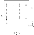
- Fig. 2 is a plan view illustrating a configuration of the nozzle plate.
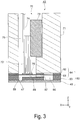
- Fig. 3 is a cross-sectional view illustrating an internal configuration of the discharging head. Next, a configuration of the discharging head 42 will be described with reference to Figs. 2 and 3 .
- the discharging head 42 includes a nozzle plate 48 provided with a plurality of nozzle columns 49 configured to discharge ink as liquid.
- the nozzle plate 48 includes the nozzle columns 49 including a plurality of (for example, 180) nozzles 47 formed along the Y axis direction.
- the nozzle plate 48 includes four nozzle columns 49 configured to discharge different kinds of ink.
- the nozzle columns 49 correspond to ink such as cyan (C), magenta (M), yellow (Y), and black (K), respectively.
- C cyan
- M magenta
- Y yellow
- K black
- the kinds and the number of kinds of ink, the number of the nozzles 47, and the number of the nozzle columns 49 are examples, and are not limited to these examples.
- the plurality of nozzle columns 49 may be configured to discharge the same kind of ink.
- the discharging head 42 includes a vibrator unit 70 including, as a unit, a plurality of piezoelectric vibrators 72, a fixing plate 73, a flexible cable 74, and the like, a case 71 capable of accommodating the vibrator unit 70, and a flow channel unit 80 bonded to a tip face of the case 71.
- a vibrator unit 70 including, as a unit, a plurality of piezoelectric vibrators 72, a fixing plate 73, a flexible cable 74, and the like, a case 71 capable of accommodating the vibrator unit 70, and a flow channel unit 80 bonded to a tip face of the case 71.
- the case 71 is a block member made of a synthetic resin and provided with an accommodation space 75 including an open tip and an open end.
- the vibrator unit 70 is accommodated and fixed in the accommodation space 75.
- the piezoelectric vibrators 72 are each formed in a comb-tooth shape elongated in a longitudinal direction.
- the piezoelectric vibrators 72 are laminated type piezoelectric vibrators each including piezoelectric elements and inner electrodes alternately laminated one on another, and are longitudinal-vibration-mode piezoelectric vibrators stretchable in the longitudinal direction orthogonal to a lamination direction. Then, a tip face of each of the piezoelectric vibrators 72 is bonded to an island part 76 of the flow channel unit 80. Note that the piezoelectric vibrators 72 behave in a manner similar to capacitors. That is, when supply of a signal is stopped, potentials of the piezoelectric vibrators 72 are maintained at potentials used immediately before the supply of a signal is stopped.
- the flow channel unit 80 includes the nozzle plate 48 disposed on one of face sides of a flow channel forming substrate 83, and an elastic plate 84 disposed on the other face side opposite to the face side on which the nozzle plate 48 is disposed, and the nozzle plate 48 and the elastic plate 84 are laminated one on another with the flow channel forming substrate 83 interposed between the nozzle plate 48 and the elastic plate 84.
- the nozzle plate 48 is bonded to the flow channel forming substrate 83 via an adhesive member.
- an adhesive member an epoxy adhesive, an acrylic adhesive, or the like can be adopted.
- the nozzle plate 48 includes a thinner metallic plate material (for example, a stainless-steel plate) provided with the plurality of nozzles 47 formed along the Y axis direction.
- the flow channel forming substrate 83 is a plate member provided with a series of ink flow channels each including a common ink chamber 86, an ink supplying port 87, a pressure chamber 88, and a nozzle communication port 89.
- the flow channel forming substrate 83 is prepared by etching a silicon wafer.
- the elastic plate 84 includes a composite plate material of a double structure including a resin film 81 laminated on a support plate 82 made of stainless-steel, and includes the island part 76 formed by forming the support plate 82 in a ring shape at a portion corresponding to the pressure chamber 88.
- the series of ink flow channels passing from the common ink chamber 86, through the pressure chamber 88, to the nozzles 47 are each formed for each of the nozzles 47.
- the piezoelectric vibrators 72 are electrically charged and discharged and thus, deform. That is, the piezoelectric vibrators 72 of a longitudinal vibration mode contract in a vibrator longitudinal direction through the charging, and stretch in the vibrator longitudinal direction through the discharging. Accordingly, when a potential rises through the charging, the island part 76 is pulled toward the piezoelectric vibrators 72 side, and the resin film 81 around the island part 76 deforms, and then the pressure chamber 88 expands. Moreover, when the potential lowers through the discharging, the pressure chamber 88 contracts.
- volume of the pressure chamber 88 can be controlled in accordance with a potential, pressure fluctuation can be caused in ink in the pressure chamber 88, and the ink can be discharged from the nozzles 47.
- the pressure chamber 88 having a normal capacity (reference volume) is caused to expand, the pressure chamber 88 is then caused to promptly contract and thus, ink droplets can be discharged.
- the configuration using the piezoelectric vibrators 72 of a longitudinal vibration type is described as an example, but is not limited to this example.
- flexural-deformation type piezoelectric vibrators each including a lower electrode, a piezoelectric layer, and an upper electrode laminated and formed one on another may be used.
- a so-called electrostatic type actuator configured to generate static electricity between a vibration plate and an electrode to deform the vibration plate by the electrostatic force, and to cause nozzles to discharge droplets may be used.
- the configuration may include a head unit configured to use a heating element to generate bubbles in nozzles, and to cause the nozzles to discharge ink as droplets by the bubbles.
- Fig. 4 is a side view illustrating configurations of the discharging head and the suction unit.
- Fig. 5 is a cross-sectional view taken along line A-A in Fig. 4 .
- Fig. 6 is a cross-sectional view taken along line B-B in Fig. 4 .
- a configuration of the cap 44 will be described with reference to Figs. 4 to 6 . Note that Figs. 4 to 6 illustrate a state where the cap 44 comes into contact with the nozzle plate 48.
- the cap 44 has a box shape including a bottom and no lid and formed with a side wall 44a having a frame shape and a bottom plate 44b.
- the bottom plate 44b includes a discharge port 44d configured to discharge sucked ink in the cap 44.
- the cap 44 includes support parts 44c each having a plate shape and each configured to come into contact with an area between the nozzle columns 49 in a state where the cap 44 is in contact with the discharging head 42 (nozzle plate 48), and to support the nozzle plate 48.
- a plurality of the support parts 44c are provided.
- the three support parts 44c are provided between the four nozzle columns 49.
- an effect of suppressing peeling off of the nozzle plate 48 can be improved.
- a height of each of the support parts 44c is identical to a height of the side wall 44a forming an outer circumference of the cap 44, the side wall 44a and the support parts 44c simultaneously come into contact with the nozzle plate 48.
- an impact caused when the support parts 44c come into contact with the nozzle plate 48 can be mitigated.
- the support parts 44c define regions 49a surrounding the nozzle columns 49.
- the side wall 44a and the support parts 44c define the four regions 49a.
- the cap 44 is configured to come into contact with the nozzle plate 48 to surround the respective nozzle columns 49.
- the regions 49a are in communication with one another.
- At least one of both ends of each of the support parts 44c is separated away from the side wall 44a of the cap 44.
- both the ends of each of the support parts 44c are separated away from the side wall 44a and thus, the plurality of regions 49a defined by the support parts 44c are in communication with one another.
- the plurality of regions 49a can be negatively pressurized by the one negative pressure pump 46.
- Rigidity of each of the support parts 44c is preferably lower than rigidity of the side wall 44a forming the outer circumference of the cap 44.
- a material of the support parts 44c is identical to a material of the side wall 44a.
- the cap 44 including the support parts 44c can be made by molding of an elastic material such as an elastomer.
- a thickness T2 of each of the support parts 44c is smaller than a thickness T1 of the side wall 44a.
- rigidity of each of the support parts 44c can be lower than rigidity of the side wall 44a.
- the cap 44 includes the support parts 44c each configured to come into contact with an area between the nozzle columns 49 in a state where the cap 44 is in contact with the nozzle plate 48, and to support the nozzle plate 48.
- the support parts 44c each configured to come into contact with an area between the nozzle columns 49 in a state where the cap 44 is in contact with the nozzle plate 48, and to support the nozzle plate 48.
- the cap 44 configured to suppress peeling off of the nozzle plate 48 due to time-degraded bond strength of an adhesive bonding the nozzle plate 48 and the flow channel forming substrate 83 and due to suction force generated by a suction operation of the negative pressure pump 46 can be provided.
- the support parts 44c define the regions 49a surrounding the nozzle columns 49. Both the ends of each of the support parts 44c are separated away from the side wall 44a and thus, the plurality of regions 49a defined by the support parts 44c are in communication with one another. Thus, the plurality of regions 49a can be pressurized negatively by the negative pressure pump 46.
- the cap 44 includes the plurality of support parts 44c, an effect of suppressing peeling off of the nozzle plate 48 can be improved.
- each of the support parts 44c is identical to the height of the side wall 44a forming the outer circumference of the cap 44, the side wall 44a and the support parts 44c simultaneously come into contact with the nozzle plate 48. Thus, an impact caused when the support parts 44c come into contact with the nozzle plate 48 can be mitigated.
- each of the support parts 44c is lower than the rigidity of the side wall 44a forming the outer circumference of the cap 44, an impact caused when the support parts 44c come into contact with the nozzle plate 48 can be mitigated.
- the rigidity of each of the support parts 44c can be lower than the rigidity of the side wall 44a.
- the printing apparatus 100 includes the discharging head 42 including the nozzle plate 48 provided with the plurality of nozzle columns 49 configured to discharge liquid, and the cap 44.
- the cap 44 includes the support parts 44c each configured to come into contact with an area between the nozzle columns 49 in a state where the cap 44 is in contact with the nozzle plate 48, and to support the nozzle plate 48.
- the center part of the nozzle plate 48 is supported by the support parts 44c.
- the printing apparatus 100 configured to suppress peeling off of the nozzle plate due to time-degraded bond strength of an adhesive bonding the nozzle plate 48 and the flow channel forming substrate 83 and due to suction force generated by a suction operation of the negative pressure pump 46 can be provided.
- Fig. 7 is a cross-sectional view taken along line A-A in Fig. 4 , and illustrating a configuration of a cap according to Modified Example 1.
- Fig. 8 is a cross-sectional view taken along line B-B in Fig. 4 .
- a configuration of a cap 144 according to the modified example will be described with reference to Figs. 7 and 8 . Note that components identical to the components in the exemplary embodiment described above are denoted by the identical reference signs, and redundant description for such components will be omitted.
- the cap 144 includes support parts 144c each having a plate shape and each configured to come into contact with an area between nozzle columns 49 in a state where the cap 144 is in contact with a discharging head 42 (nozzle plate 48), and to support the nozzle plate 48.
- nozzle plate 48 a discharging head 42
- the cap 144 includes support parts 144c each having a plate shape and each configured to come into contact with an area between nozzle columns 49 in a state where the cap 144 is in contact with a discharging head 42 (nozzle plate 48), and to support the nozzle plate 48.
- a side wall 44a and the support parts 144c define four regions 49a surrounding the nozzle columns 49.
- the support parts 144c have plate shapes extending in mutually approaching directions from the side wall 44a forming the outer circumference of the cap 144. Then, tips of the support parts 144c are separated away from each other and thus, when the cap 44 is in contact with the nozzle plate 48, the plurality of regions 49a defined by the support parts 144c are in communication with one another. Thus, the plurality of regions 49a can be pressurized negatively by the one negative pressure pump 46.
- Fig. 9 is a cross-sectional view taken along line A-A in Fig. 4 , and illustrating a configuration of a cap according to Modified Example 2.
- Fig. 10 is cross-sectional view taken along line B-B in Fig. 4 .
- a configuration of a cap 244 according to the modified example will be described with reference to Figs. 9 and 10 . Note that components identical to the components in the exemplary embodiment described above are denoted by the identical reference signs, and redundant description for such components will be omitted.
- the cap 244 includes support parts 244c each having a plate shape and each configured to come into contact with an area between nozzle columns 49 in a state where the cap 244 is in contact with a discharging head 42 (nozzle plate 48), and to support the nozzle plate 48.
- nozzle plate 48 a discharging head 42
- the cap 244 includes support parts 244c each having a plate shape and each configured to come into contact with an area between nozzle columns 49 in a state where the cap 244 is in contact with a discharging head 42 (nozzle plate 48), and to support the nozzle plate 48.
- a side wall 44a and the support parts 244c define four regions 49a surrounding the nozzle columns 49.
- the support parts 244c each include both ends coupled to the side wall 44a forming an outer circumference of the cap 244. Then, a part on a side opposite (- side in the Z axis direction) to a side of each of the support parts 244c configured to come into contact with the nozzle plate 48 is separated away from an inner bottom surface 244e of the cap 244.
- a communication hole 41 having for example an arc shape is formed at a lower center part of each of the support parts 244c.
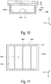
- Fig. 11 is a plan view illustrating a configuration of a cap according to Modified Example 3.
- a configuration of a cap 344 according to the modified example will be described with reference to Fig. 11 .
- Fig. 11 is a plan view as viewed in a perpendicular direction (+ side in the Z axis direction).
- components identical to the components in the exemplary embodiment and Modified Example 2 described above are denoted by the identical reference signs, and redundant description for such components will be omitted.
- support parts 244c are configured to be detachably attached to a side wall 344a forming an outer circumference of the cap 344.
- Two inner walls of the side wall 344a facing each other in a direction (Y axis direction) along nozzle columns 49 are each provided with a plurality of slits 341.
- a width of each of the slits 341 is slightly greater than a width of each of the support parts 244c, and the slits 341 detachably support the support parts 244c.
- Fig. 12 is a side view illustrating a configuration of a suction unit according to Modified Example 4.
- the configuration of the suction unit according to the modified example will be described with reference to Fig. 12 .
- components identical to the components in the exemplary embodiment described above are denoted by the identical reference signs, and redundant description for such components will be omitted.
- a suction unit 445 includes a cap 44 and a syringe 446.
- the negative pressure pump 46 described in the exemplary embodiment is replaced with the syringe 446 by a user. Then, the user operates the syringe 446 to negatively pressurize an inside of the cap 44 to fill the discharging head 42 with the ink.
- the discharging head 42 can be filled with the ink more efficiently than in the case of using the negative pressure pump 46.
- the inside of the cap 44 is highly negatively pressurized, and a nozzle plate 48 may peel off from a flow channel forming substrate 83.
- the cap 44 according to the modified example includes support parts 44c configured to support the nozzle plate 48, the cap 44 also has an effect of suppressing peeling off of the nozzle plate 48 at the time of ink filling.
Abstract
Description
- The invention relates to a cap and a printing apparatus.
- In the related art, there is known an ink jet-type printing apparatus configured to discharge ink or the like from nozzles of a discharging head to a medium to print an image and the like. In such a printing apparatus, owing to ink thickened around openings of the nozzles by evaporation of an ink solvent, air bubbles mixed into the discharging head, and the like, abnormal discharge of ink may occur. Therefore, a printing apparatus includes a cap configured to come into contact with a nozzle plate provided with nozzles, and to discharge thickened ink and air bubbles by application of negative pressure. Various elaborated caps are conceivable. For example,
JP-A-7-132608 - However, in an industry-use printing apparatus, a large-sized discharging head has been used to satisfy demands for higher quality in color printing, improved production efficiency, and the like. Thus, a nozzle plate and a cap configured to come into contact with the nozzle plate have also been large-sized. The nozzle plate is bonded to a flow channel forming substrate configured to form an ink flow channel in the discharging head. When the printing apparatus is used for a longer period of time, bond strength of the nozzle plate time-degrades. In addition to this, when a suction operation including bringing the cap into contact with the nozzle plate to negatively pressurize an inside of the cap is repeatedly performed, a center part of the nozzle plate not coming into contact with an outer circumference of the cap may peel off from the flow channel forming substrate owing to the negative pressure.
- The invention is made to address at least a part of the above-described issues, and can be realized as the following modes or application examples.
- A cap according to the application example is a cap configured to come into contact with a discharging head including a nozzle plate provided with a plurality of nozzle columns configured to discharge liquid, and to cover the nozzle plate, and the cap includes support parts each configured to come into contact with an area between the nozzle columns and to support the nozzle plate.
- According to the application example, the cap includes the support parts configured to come into contact with the area between the plurality of nozzle columns formed on the nozzle plate. In a case where the cap is in contact with the nozzle plate, a center part of the nozzle plate is supported by the support parts. Thus, even when negative pressure is applied to the cap being in contact with the nozzle plate having time-degraded bond strength, deformation of the center part of the nozzle plate is suppressed by the support parts. Accordingly, the cap configured to suppress peeling off of the nozzle plate due to time-degraded bond strength of the nozzle plate forming the discharging head and due to a suction operation can be provided.
- In the cap according to the application example described above, preferably, the support parts define regions surrounding the nozzle columns, and when the cap is in contact with the nozzle plate, the regions are in communication with one another.
- According to the application example, when the cap is in contact with the nozzle plate, the support parts define the regions surrounding the nozzle columns. Since a plurality of the regions being defined are in communication with one another, the plurality of regions can be pressurized negatively by one negative pressure apparatus.
- In the cap according to any of the application examples described above, preferably, the support parts have a plate shape, and at least one of both ends of each of the support parts is separated at least in part away from a side wall forming an outer circumference of the cap.
- According to the application example, the support parts each have a plate shape, and at least one of both the ends of each of the support parts is separated away from the side wall forming the outer circumference of the cap. Thus, the plurality of regions defined by the support parts can be in communication with one another. In one variation, both ends of each of the support parts are joined to the side wall of the cap, but one or both ends is separated in part from the side wall so the regions can be in communication.
- In the cap according to any of the application examples described above, preferably, the support parts have plate shapes extending in mutually approaching directions from the side wall forming the outer circumference of the cap, and tips of the support parts are separated away from each other.
- According to the application example, the support parts have the plate shapes extending in the mutually approaching directions from the side wall forming the outer circumference of the cap, and the tips of the support parts are separated away from each other. Thus, the plurality of regions defined by the support parts can be in communication with one another.
- In the cap according to any of the application examples described above, preferably, the support parts each have a plate shape including both ends coupled to the side wall forming the outer circumference of the cap, and at least a part on a side opposite to a side of each of the support parts configured to come into contact with the nozzle plate is separated away from an inner bottom surface.
- According to the application example, the support parts each have the plate shape including both the ends coupled to the side wall forming the outer circumference of the cap. At least a part on the side opposite to the side of each of the support parts configured to come into contact with the nozzle plate is separated away from the inner bottom surface of the cap. Thus, the plurality of regions defined by the support parts can be in communication with one another.
- The cap according to any of the application examples described above preferably includes a plurality of the support parts.
- According to the application example, since the cap includes the plurality of support parts, an effect of suppressing peeling off of the nozzle plate can be improved.
- In the cap according to any of the application examples described above, a height of the support parts is preferably identical to a height of the side wall forming the outer circumference of the cap.
- According to the application example, since the height of each of the support parts is identical to the height of the side wall forming the outer circumference of the cap, the side wall and the support parts simultaneously come into contact with the nozzle plate. Thus, an impact caused when the support parts come into contact with the nozzle plate can be mitigated.
- In the cap according to any of the application examples described above, rigidity of each of the support parts is preferably lower than rigidity of the side wall forming the outer circumference of the cap.
- According to the application example, since the rigidity of each of the support parts is lower than the rigidity of the side wall forming the outer circumference of the cap, an impact caused when the support parts come into contact with the nozzle plate can be mitigated.
- In the cap according to the application example described above, preferably, a material of the support parts is identical to a material of the side wall, and a thickness of the support parts is smaller than a thickness of the side wall.
- According to the application example, since the material of the support parts is identical to the material of the side wall forming the outer circumference of the cap, and the thickness of each of the support parts is smaller than the thickness of each of the side wall, rigidity of each of the support parts can be lower than rigidity of the side wall.
- In the cap according to any of the application examples described above, preferably, the support parts are configured to be detachably attached to the side wall forming the outer circumference of the cap, and positions for the support parts to be mounted are adjustable.
- According to the application example, the support parts are configured to be detachably attached to the side wall forming the outer circumference of the cap. Moreover, since the mounting positions for the support parts to be mounted are adjustable, a user can customize the cap in accordance with the nozzle columns of the discharging head to be used.
- A printing apparatus according to the application example includes a discharging head including a nozzle plate provided with a plurality of nozzle columns configured to discharge liquid, and the cap according to any one of Application Examples 1 to 10.
- According to the application example, the printing apparatus includes the discharging head including the nozzle plate provided with the plurality of nozzle columns configured to discharge liquid, and the cap according to any one of Application Examples 1 to 10. When the cap is in contact with the nozzle plate, the center part of the nozzle plate is supported by the support parts provided to the cap. Thus, even when negative pressure is applied to the cap being in contact with the nozzle plate having time-degraded bond strength, deformation of the center part of the nozzle plate is suppressed by the support parts. Accordingly, the printing apparatus configured to suppress peeling off of the nozzle plate due to time-degraded bond strength of the nozzle plate forming the discharging head and due to a suction operation can be provided.
- Embodiments of the invention will now be described by way of example only with reference to the accompanying drawings, wherein like numbers reference like elements.
-
Fig. 1 is a schematic view illustrating a schematic overall configuration of a printing apparatus according to an exemplary embodiment. -
Fig. 2 is a plan view illustrating a configuration of a nozzle plate. -
Fig. 3 is a cross-sectional view illustrating an internal configuration of a discharging head. -
Fig. 4 is a side view illustrating configurations of the discharging head and a suction unit. -
Fig. 5 is a cross-sectional view taken along line A-A inFig. 4 . -
Fig. 6 is a cross-sectional view taken along line B-B inFig. 4 . -
Fig. 7 is a cross-sectional view taken along line A-A inFig. 4 , and illustrating a configuration of a cap according to Modified Example 1. -
Fig. 8 is a cross-sectional view taken along line B-B inFig. 4 . -
Fig. 9 is a cross-sectional view taken along line A-A inFig. 4 , and illustrating a configuration of a cap according to Modified Example 2. -
Fig. 10 is a cross-sectional view taken along line B-B inFig. 4 . -
Fig. 11 is a plan view illustrating a configuration of a cap according to Modified Example 3. -
Fig. 12 is a side view illustrating a configuration of a suction unit according to Modified Example 4. - Exemplary embodiments of the invention will be described below with reference to the drawings. Note that, in each of the figures below, to illustrate each of layers or each of members at a recognizable size, a scale of each of the layers or each of the members is different from an actual scale.
- Moreover, for convenience of description, in each figure, three axes of an X axis, a Y axis, and a Z axis orthogonal to one another are illustrated, and a tip side of an arrow illustrating each axis direction is referred to as a "+ side", and a base end side is referred to as a "- side". Moreover, hereinafter, a direction parallel to the X axis is referred to as an "X axis direction", a direction parallel to the Y axis is referred to as a "Y axis direction", and a direction parallel to the Z axis is referred to as a "Z axis direction".
-
Fig. 1 is a schematic view illustrating a schematic overall configuration of a printing apparatus according to an exemplary embodiment. First, a schematic configuration of aprinting apparatus 100 according to the exemplary embodiment will be described with reference toFig. 1 . Note that in the exemplary embodiment, theprinting apparatus 100 of an ink jet-type configured to form an image and the like onto a medium 95 to perform printing onto the medium 95 will be described as an example. - As illustrated in
Fig. 1 , theprinting apparatus 100 includes amedium transporting unit 20, a mediumfitting part 60, aprinting unit 40, a dryingunit 27, acleaning unit 50, asuction unit 45, and the like. Furthermore, theprinting apparatus 100 includes acontroller 1 configured to control each of these components. Each component of theprinting apparatus 100 is attached to aframe part 92. - The
medium transporting unit 20 is configured to transport the medium 95 in a transporting direction (a +Y axis direction in the printing unit 40). Themedium transporting unit 20 includes amedium supplying unit 10, transportingrollers belt 23, a belt-rotatedroller 24, a belt-drivingroller 25, transportingrollers medium collecting part 30. First, a transporting path for the medium 95 from themedium supplying unit 10 to themedium collecting part 30 will be described. Note that in the exemplary embodiment, a direction along gravity is referred to as the Z axis, a direction in which the medium 95 is transported in theprinting unit 40 is referred to as the Y axis, and a width direction of the medium 95 intersecting both the Z axis and the Y axis is referred to as the X axis. - The
medium supplying unit 10 is configured to supply the medium 95 onto which an image is to be formed to theprinting unit 40 side. As the medium 95, for example, natural fiber, cotton, silk, hemp, mohair, wool, cashmere, regenerated fiber, synthetic fiber, nylon, polyurethane, polyester, and woven cloth or non-woven cloth made by mixed spinning of any of the materials can be used. To the woven cloth or the non-woven cloth, a pretreatment agent for promoting a color developing property and a fixing property may be applied. Themedium supplying unit 10 includes a feedingshaft part 11 and a bearingpart 12. The feedingshaft part 11 is formed in a cylindrical shape or a columnar shape, and is provided rotatably in a circumferential direction. The medium 95 having a belt shape is wound around the feedingshaft part 11 to form a roll shape. The feedingshaft part 11 is detachably attached to the bearingpart 12. Thus, the medium 95 being wound beforehand onto the feedingshaft part 11 can be attached to the bearingpart 12 together with the feedingshaft part 11. Note that a winding direction of the medium 95 held by the feedingshaft part 11 is an example, and is not limited to this example. A configuration in which the medium 95 is supplied from a roll with a recording surface facing inside may be applied. - The bearing
part 12 rotatably supports both ends in an axis direction of the feedingshaft part 11. Themedium supplying unit 10 includes a rotation driver (not illustrated) configured to rotate and drive the feedingshaft part 11. The rotation driver rotates the feedingshaft part 11 in a direction in which the medium 95 is supplied. An operation of the rotation driver is controlled by thecontroller 1. The transportingrollers medium supplying unit 10 to the transportingbelt 23. - The transporting
belt 23 transports the medium 95 in the transporting direction (+Y axis direction). The transportingbelt 23 has a belt shape including both ends coupled to each other and is formed in an endless manner, and the transportingbelt 23 is hung on the belt-rotatedroller 24 and the belt-drivingroller 25. The transportingbelt 23 is held in a state where predetermined tension acts on the transportingbelt 23 to cause a part of the transportingbelt 23 between the belt-rotatedroller 24 and the belt-drivingroller 25 to be parallel to afloor 99. A surface (support face) 23a of the transportingbelt 23 is provided with anadhesive layer 29 onto which the medium 95 adheres. The transportingbelt 23 supports (holds) the medium 95 supplied from the transportingroller 22 and fitted onto theadhesive layer 29 by the mediumfitting part 60 described later. Thus, stretchable fiber and the like can be handled as the medium 95. - The belt-rotated
roller 24 and the belt-drivingroller 25 support an innercircumferential surface 23b of the transportingbelt 23. Note that a configuration in which a support part configured to support the transportingbelt 23 is provided between the belt-rotatedroller 24 and the belt-drivingroller 25 may be applied. - The belt-driving
roller 25 includes a motor (not illustrated) configured to rotate and drive the belt-drivingroller 25. When the belt-drivingroller 25 is rotated and driven, the transportingbelt 23 rotates in association with the rotation of the belt-drivingroller 25, and the belt-rotatedroller 24 rotates in association with the rotation of the transportingbelt 23. In association with the rotation of the transportingbelt 23, the medium 95 supported by the transportingbelt 23 is transported in the predetermined transporting direction (+Y axis direction), and an image is formed on the medium 95 by theprinting unit 40 described later. - In the exemplary embodiment, the medium 95 is supported on a side (+Z axis side) where the
surface 23a of the transportingbelt 23 faces theprinting unit 40, and the medium 95 is transported together with the transportingbelt 23 from the belt-rotatedroller 24 side to the belt-drivingroller 25 side (+Y axis direction). Moreover, on a side (-Z axis side) where thesurface 23a of the transportingbelt 23 faces thecleaning unit 50, only the transportingbelt 23 moves from the belt-drivingroller 25 side to the belt-rotatedroller 24 side (-Y axis direction). Note that description is made above on the transportingbelt 23 including theadhesive layer 29 onto which the medium 95 is fitted, but the transportingbelt 23 is not limited to this. For example, the transporting belt may be an electrostatic attraction type transporting belt configured to attract a medium onto the belt by static electricity. - The transporting
roller 26 is configured to remove the medium 95 on which an image is formed from theadhesive layer 29 of the transportingbelt 23. The transportingrollers belt 23 to themedium collecting part 30. - The
medium collecting part 30 is configured to collect the medium 95 transported by themedium transporting unit 20. Themedium collecting part 30 includes a windingshaft part 31 and a bearingpart 32. The windingshaft part 31 is formed in a cylindrical shape or a columnar shape, and is provided rotatably in a circumferential direction. The medium 95 having a belt shape is wound onto the windingshaft part 31 to form a roll shape. The windingshaft part 31 is detachably attached to the bearingpart 32. Thus, the medium 95 wound onto the windingshaft part 31 can be detached together with the windingshaft part 31. - The bearing
part 32 rotatably supports both ends in an axis line direction of the windingshaft part 31. Themedium collecting part 30 includes a rotation driver (not illustrated) configured to rotate and drive the windingshaft part 31. The rotation driver rotates the windingshaft part 31 in a direction in which the medium 95 is wound. An operation of the rotation driver is controlled by thecontroller 1. Note that a winding direction of the medium 95 held by themedium collecting part 30 illustrated inFig. 1 is an example, and the configuration is not limited to this example. A configuration in which the medium 95 is wound with a recording surface of the medium 95 facing inside may be applied. - Next, each component provided along the
medium transporting unit 20 will be described. - The medium
fitting part 60 is configured to fit the medium 95 onto the transportingbelt 23. The mediumfitting part 60 is provided on an upstream side (-Y axis side) of theprinting unit 40. The mediumfitting part 60 includes apress roller 61, apress roller driver 62, and aroller support part 63. Thepress roller 61 is formed in a cylindrical shape or a columnar shape, and is provided rotatably in a circumferential direction. Thepress roller 61 is disposed to have an axis line direction intersecting the transporting direction, and to rotate around the axis line in a direction along the transporting direction. Theroller support part 63 is provided on the innercircumferential surface 23b side of the transportingbelt 23 facing thepress roller 61 with the transportingbelt 23 interposed between theroller support part 63 and thepress roller 61. - The
press roller driver 62 is configured to press thepress roller 61 downward (-Z axis side) in a perpendicular direction to move thepress roller 61 in the transporting direction (+Y axis direction) and a direction opposite to the transporting direction (-Y axis direction). The medium 95 superimposed on the transportingbelt 23 is pressed onto the transportingbelt 23 between thepress roller 61 and theroller support part 63. Thus, the medium 95 can securely adhere onto theadhesive layer 29 provided on thesurface 23a of the transportingbelt 23, and separation of the medium 95 from the transportingbelt 23 can be prevented. - The
printing unit 40 is disposed at a position above (+Z axis side) a disposition position of the transportingbelt 23, and is configured to perform printing onto the medium 95 placed on thesurface 23a of the transportingbelt 23. Theprinting unit 40 includes a discharginghead 42 configured to discharge a plurality of droplets of ink toward the medium 95, acarriage 43 on which the discharginghead 42 is mounted, acarriage transporting unit 93 configured to move thecarriage 43 in the width direction (X axis direction) of the medium 95 intersecting the transporting direction, and the like. The discharginghead 42 is supplied with various kinds of ink through anink supplying tube 79 configured to supply the ink as liquid from an ink tank (not illustrated). - The
carriage transporting unit 93 is configured to move the discharginghead 42 together with thecarriage 43 back and forth in the X axis direction. Thecarriage transporting unit 93 is provided above the transporting belt 23 (+Z axis direction side), and includes a pair ofguide rails carriage 43. Thecarriage 43 is guided by theguide rails guide rails carriage 43 is movable back and forth in the X axis direction. - The
carriage transporting unit 93 includes a moving mechanism (not illustrated) and a power source (not illustrated). As the moving mechanism, a mechanism including a combination of a ball screw and a ball nut, a linear guide mechanism, or the like can be adopted. Further, thecarriage transporting unit 93 is provided with a motor (not illustrated) as a power source to move thecarriage 43 along the X axis direction. As the motor, any kind of motors such as a stepping motor, a servo motor, and a linear motor can be adopted. When the motor is driven by control of thecontroller 1, the discharginghead 42 moves together with thecarriage 43 back and forth along the X axis direction. - The
controller 1 controls an operation of each component. For example, thecontroller 1 alternately repeats main scanning including controlling thecarriage transporting unit 93 and the discharginghead 42 to cause the discharginghead 42 to discharge the ink, and to move the discharging head 42 (carriage 43), and sub scanning including controlling themedium transporting unit 20 to transport the medium 95 in the transporting direction and thus, an image and the like are formed on the medium 95. Note that in the exemplary embodiment, the serial-head type discharging head being mounted on thecarriage 43 configured to move back and forth, and being configured to move in the width direction (X axis direction) of the medium 95 and to discharge ink is exemplified as the discharginghead 42, but the discharginghead 42 may be a line-head type discharging head extending and fixed to be arranged in the width direction of the medium 95. - The
suction unit 45 includes acap 44 configured to come into contact with the discharginghead 42 to cover the nozzle plate 48 (seeFig. 4 ), and anegative pressure pump 46 configured to negatively pressurize an inside of thecap 44. Moreover, thesuction unit 45 includes a lifting device (not illustrated) configured to raise thecap 44 to bring thecap 44 into contact with the discharginghead 42. Thesuction unit 45 covers the discharginghead 42 with thecap 44, and also causes thenegative pressure pump 46 to negatively pressurize the inside of thecap 44 to suck ink in the discharginghead 42. Thus, air bubbles, foreign materials, and the like mixed into the discharginghead 42 can be removed, and thenozzles 47 having discharge defects due to the air bubbles and the foreign materials can be recovered. - Moreover, the
suction unit 45 functions as filling means used in filling the discharginghead 42 with ink from the ink tank. The ink sucked by thesuction unit 45 is stored in a waste tank (not illustrated) via a discharging path 97 (seeFig. 4 ). Note that a configuration in which for example, a wiping part configured to wipe ink and foreign materials adhering onto thenozzle plate 48, and a flushing part configured to capture droplets generated when ink thickened in the discharginghead 42 is discharged are provided in addition to thesuction unit 45 may be applied. Thesuction unit 45 is provided to one side of thebelt 23 in width direction (X axis direction). - The drying
unit 27 is provided between the transportingroller 26 and the transportingroller 28. The dryingunit 27 is configured to dry ink discharged onto the medium 95. The dryingunit 27 includes, for example, an infrared (IR) heater, and can drive the IR heater to dry ink discharged onto the medium 95 for a short period of time. Thus, the medium 95 having a belt shape on which an image and the like are formed can be wound onto the windingshaft part 31. - The
cleaning unit 50 is configured to clean the transportingbelt 23. Thecleaning unit 50 includes a cleaningpart 51, apressing part 52, and a movingpart 53. The movingpart 53 is capable of moving thecleaning unit 50 in an integrated manner along thefloor 99 to fix thecleaning unit 50 at a predetermined position. Thecleaning unit 50 is disposed between the belt-rotatedroller 24 and the belt-drivingroller 25 in the Y axis direction. - The
pressing part 52 is a lifting device including, for example, anair cylinder 56 and aball bushing 57, and is configured to cause thecleaning part 51 provided above thepressing part 52 to be movable between a cleaning position and a retraction position. The cleaning position refers to a position where a cleaningroller 58 and ablade 55 come into contact with the transportingbelt 23. The retraction position refers to a position where the cleaningroller 58 and theblade 55 are separated away from the transportingbelt 23. At the cleaning position, the cleaningpart 51 cleans the surface (support face) 23a of the transportingbelt 23 from below (-Z axis direction). Note thatFig. 1 illustrates a case where the cleaningpart 51 is raised to be disposed at the cleaning position. - The cleaning
part 51 includes acleaning tank 54, the cleaningroller 58, and theblade 55. Thecleaning tank 54 is a tank configured to store a cleaning liquid used to clean ink and foreign materials adhering onto thesurface 23a of the transportingbelt 23. The cleaningroller 58 and theblade 55 are provided inside thecleaning tank 54. As the cleaning liquid, for example, water or a water soluble solvent (an alcohol aqueous solution or the like) can be used, and a surfactant or an anti-foaming agent may be added as necessary. - A lower side (-Z axis side) of the cleaning
roller 58 is immersed in the cleaning liquid stored in thecleaning tank 54. When the cleaningroller 58 rotates at the cleaning position, the cleaning liquid is supplied to thesurface 23a of the transportingbelt 23, and also the cleaningroller 58 and the transportingbelt 23 slide on each other. Thus, ink adhering onto the transportingbelt 23, fiber of the medium 95, and the like are removed by the cleaningroller 58. - The
blade 55 can be formed of a flexible material such as silicon rubber. Theblade 55 is provided on a downstream side of the cleaningroller 58 in a moving direction of the transportingbelt 23. The transportingbelt 23 and theblade 55 slide against each other and thus, the cleaning liquid remaining on thesurface 23a of the transportingbelt 23 is removed. -
Fig. 2 is a plan view illustrating a configuration of the nozzle plate.Fig. 3 is a cross-sectional view illustrating an internal configuration of the discharging head. Next, a configuration of the discharginghead 42 will be described with reference toFigs. 2 and3 . - The discharging
head 42 includes anozzle plate 48 provided with a plurality ofnozzle columns 49 configured to discharge ink as liquid. - The
nozzle plate 48 includes thenozzle columns 49 including a plurality of (for example, 180)nozzles 47 formed along the Y axis direction. Thenozzle plate 48 includes fournozzle columns 49 configured to discharge different kinds of ink. Thenozzle columns 49 correspond to ink such as cyan (C), magenta (M), yellow (Y), and black (K), respectively. Note that the kinds and the number of kinds of ink, the number of thenozzles 47, and the number of thenozzle columns 49 are examples, and are not limited to these examples. Moreover, the plurality ofnozzle columns 49 may be configured to discharge the same kind of ink. - Next, an internal structure of the discharging
head 42 will be described. - As illustrated in
Fig. 3 , the discharginghead 42 includes avibrator unit 70 including, as a unit, a plurality ofpiezoelectric vibrators 72, a fixingplate 73, aflexible cable 74, and the like, acase 71 capable of accommodating thevibrator unit 70, and aflow channel unit 80 bonded to a tip face of thecase 71. - The
case 71 is a block member made of a synthetic resin and provided with anaccommodation space 75 including an open tip and an open end. Thevibrator unit 70 is accommodated and fixed in theaccommodation space 75. - The
piezoelectric vibrators 72 are each formed in a comb-tooth shape elongated in a longitudinal direction. Thepiezoelectric vibrators 72 are laminated type piezoelectric vibrators each including piezoelectric elements and inner electrodes alternately laminated one on another, and are longitudinal-vibration-mode piezoelectric vibrators stretchable in the longitudinal direction orthogonal to a lamination direction. Then, a tip face of each of thepiezoelectric vibrators 72 is bonded to anisland part 76 of theflow channel unit 80. Note that thepiezoelectric vibrators 72 behave in a manner similar to capacitors. That is, when supply of a signal is stopped, potentials of thepiezoelectric vibrators 72 are maintained at potentials used immediately before the supply of a signal is stopped. - The
flow channel unit 80 includes thenozzle plate 48 disposed on one of face sides of a flowchannel forming substrate 83, and anelastic plate 84 disposed on the other face side opposite to the face side on which thenozzle plate 48 is disposed, and thenozzle plate 48 and theelastic plate 84 are laminated one on another with the flowchannel forming substrate 83 interposed between thenozzle plate 48 and theelastic plate 84. Thenozzle plate 48 is bonded to the flowchannel forming substrate 83 via an adhesive member. As the adhesive member, an epoxy adhesive, an acrylic adhesive, or the like can be adopted. - The
nozzle plate 48 includes a thinner metallic plate material (for example, a stainless-steel plate) provided with the plurality ofnozzles 47 formed along the Y axis direction. The flowchannel forming substrate 83 is a plate member provided with a series of ink flow channels each including acommon ink chamber 86, anink supplying port 87, apressure chamber 88, and anozzle communication port 89. In the exemplary embodiment, the flowchannel forming substrate 83 is prepared by etching a silicon wafer. Theelastic plate 84 includes a composite plate material of a double structure including aresin film 81 laminated on asupport plate 82 made of stainless-steel, and includes theisland part 76 formed by forming thesupport plate 82 in a ring shape at a portion corresponding to thepressure chamber 88. - In the discharging
head 42, the series of ink flow channels passing from thecommon ink chamber 86, through thepressure chamber 88, to thenozzles 47 are each formed for each of thenozzles 47. Then, thepiezoelectric vibrators 72 are electrically charged and discharged and thus, deform. That is, thepiezoelectric vibrators 72 of a longitudinal vibration mode contract in a vibrator longitudinal direction through the charging, and stretch in the vibrator longitudinal direction through the discharging. Accordingly, when a potential rises through the charging, theisland part 76 is pulled toward thepiezoelectric vibrators 72 side, and theresin film 81 around theisland part 76 deforms, and then thepressure chamber 88 expands. Moreover, when the potential lowers through the discharging, thepressure chamber 88 contracts. - Thus, since volume of the
pressure chamber 88 can be controlled in accordance with a potential, pressure fluctuation can be caused in ink in thepressure chamber 88, and the ink can be discharged from thenozzles 47. For example, once thepressure chamber 88 having a normal capacity (reference volume) is caused to expand, thepressure chamber 88 is then caused to promptly contract and thus, ink droplets can be discharged. - Note that in the exemplary embodiment, the configuration using the
piezoelectric vibrators 72 of a longitudinal vibration type is described as an example, but is not limited to this example. For example, flexural-deformation type piezoelectric vibrators each including a lower electrode, a piezoelectric layer, and an upper electrode laminated and formed one on another may be used. Moreover, as means for causing thepressure chamber 88 to expand and contract, for example, a so-called electrostatic type actuator configured to generate static electricity between a vibration plate and an electrode to deform the vibration plate by the electrostatic force, and to cause nozzles to discharge droplets may be used. Further, the configuration may include a head unit configured to use a heating element to generate bubbles in nozzles, and to cause the nozzles to discharge ink as droplets by the bubbles. -
Fig. 4 is a side view illustrating configurations of the discharging head and the suction unit.Fig. 5 is a cross-sectional view taken along line A-A inFig. 4 .Fig. 6 is a cross-sectional view taken along line B-B inFig. 4 . Next, a configuration of thecap 44 will be described with reference toFigs. 4 to 6 . Note thatFigs. 4 to 6 illustrate a state where thecap 44 comes into contact with thenozzle plate 48. - As illustrated in
Figs. 4 to 6 , thecap 44 has a box shape including a bottom and no lid and formed with aside wall 44a having a frame shape and abottom plate 44b. Thebottom plate 44b includes adischarge port 44d configured to discharge sucked ink in thecap 44. Further, thecap 44 includessupport parts 44c each having a plate shape and each configured to come into contact with an area between thenozzle columns 49 in a state where thecap 44 is in contact with the discharging head 42 (nozzle plate 48), and to support thenozzle plate 48. Thus, peeling off of the nozzle plate due to time-degraded bond strength of an adhesive bonding thenozzle plate 48 and the flowchannel forming substrate 83 and due to a suction operation of thenegative pressure pump 46 can be suppressed. - A plurality of the
support parts 44c are provided. In the exemplary embodiment, the threesupport parts 44c are provided between the fournozzle columns 49. Thus, an effect of suppressing peeling off of thenozzle plate 48 can be improved. Moreover, since a height of each of thesupport parts 44c is identical to a height of theside wall 44a forming an outer circumference of thecap 44, theside wall 44a and thesupport parts 44c simultaneously come into contact with thenozzle plate 48. Thus, an impact caused when thesupport parts 44c come into contact with thenozzle plate 48 can be mitigated. - As illustrated in
Fig. 5 , thesupport parts 44c defineregions 49a surrounding thenozzle columns 49. Inside thecap 44, theside wall 44a and thesupport parts 44c define the fourregions 49a. Thecap 44 is configured to come into contact with thenozzle plate 48 to surround therespective nozzle columns 49. When thecap 44 is in contact with thenozzle plate 48, theregions 49a are in communication with one another. At least one of both ends of each of thesupport parts 44c is separated away from theside wall 44a of thecap 44. In the exemplary embodiment, both the ends of each of thesupport parts 44c are separated away from theside wall 44a and thus, the plurality ofregions 49a defined by thesupport parts 44c are in communication with one another. Thus, the plurality ofregions 49a can be negatively pressurized by the onenegative pressure pump 46. - Rigidity of each of the
support parts 44c is preferably lower than rigidity of theside wall 44a forming the outer circumference of thecap 44. Thus, an impact caused when thesupport parts 44c come into contact with thenozzle plate 48 can be mitigated. In the exemplary embodiment, a material of thesupport parts 44c is identical to a material of theside wall 44a. Thecap 44 including thesupport parts 44c can be made by molding of an elastic material such as an elastomer. Moreover, a thickness T2 of each of thesupport parts 44c is smaller than a thickness T1 of theside wall 44a. Thus, rigidity of each of thesupport parts 44c can be lower than rigidity of theside wall 44a. - As described above, according to the
cap 44 and theprinting apparatus 100 according to the exemplary embodiment, the following effects can be achieved. - The
cap 44 includes thesupport parts 44c each configured to come into contact with an area between thenozzle columns 49 in a state where thecap 44 is in contact with thenozzle plate 48, and to support thenozzle plate 48. When thecap 44 is in contact with thenozzle plate 48, a center part of thenozzle plate 48 is supported by thesupport parts 44c. Thus, even when thecap 44 being in contact with thenozzle plate 48 having time-degraded bond strength is negatively pressurized, deformation of the center part of thenozzle plate 48 is suppressed by thesupport parts 44c. Accordingly, thecap 44 configured to suppress peeling off of thenozzle plate 48 due to time-degraded bond strength of an adhesive bonding thenozzle plate 48 and the flowchannel forming substrate 83 and due to suction force generated by a suction operation of thenegative pressure pump 46 can be provided. - The
support parts 44c define theregions 49a surrounding thenozzle columns 49. Both the ends of each of thesupport parts 44c are separated away from theside wall 44a and thus, the plurality ofregions 49a defined by thesupport parts 44c are in communication with one another. Thus, the plurality ofregions 49a can be pressurized negatively by thenegative pressure pump 46. - Since the
cap 44 includes the plurality ofsupport parts 44c, an effect of suppressing peeling off of thenozzle plate 48 can be improved. - Since the height of each of the
support parts 44c is identical to the height of theside wall 44a forming the outer circumference of thecap 44, theside wall 44a and thesupport parts 44c simultaneously come into contact with thenozzle plate 48. Thus, an impact caused when thesupport parts 44c come into contact with thenozzle plate 48 can be mitigated. - Since the rigidity of each of the
support parts 44c is lower than the rigidity of theside wall 44a forming the outer circumference of thecap 44, an impact caused when thesupport parts 44c come into contact with thenozzle plate 48 can be mitigated. - Since the material of the
support parts 44c is identical to the material of theside wall 44a, and the thickness T2 of each of thesupport parts 44c is smaller than the thickness T1 of each of theside wall 44a, the rigidity of each of thesupport parts 44c can be lower than the rigidity of theside wall 44a. - The
printing apparatus 100 includes the discharginghead 42 including thenozzle plate 48 provided with the plurality ofnozzle columns 49 configured to discharge liquid, and thecap 44. Thecap 44 includes thesupport parts 44c each configured to come into contact with an area between thenozzle columns 49 in a state where thecap 44 is in contact with thenozzle plate 48, and to support thenozzle plate 48. When thecap 44 is in contact with thenozzle plate 48, the center part of thenozzle plate 48 is supported by thesupport parts 44c. Thus, even when thecap 44 being in contact with thenozzle plate 48 having time-degraded bond strength is negatively pressurized, deformation of the center part of thenozzle plate 48 is suppressed by thesupport parts 44c. Accordingly, theprinting apparatus 100 configured to suppress peeling off of the nozzle plate due to time-degraded bond strength of an adhesive bonding thenozzle plate 48 and the flowchannel forming substrate 83 and due to suction force generated by a suction operation of thenegative pressure pump 46 can be provided. - Note that the invention is not limited to the exemplary embodiment described above, and the exemplary embodiment described above can be variously changed and modified. Modified examples will be described below.
-
Fig. 7 is a cross-sectional view taken along line A-A inFig. 4 , and illustrating a configuration of a cap according to Modified Example 1.Fig. 8 is a cross-sectional view taken along line B-B inFig. 4 . Next, a configuration of acap 144 according to the modified example will be described with reference toFigs. 7 and8 . Note that components identical to the components in the exemplary embodiment described above are denoted by the identical reference signs, and redundant description for such components will be omitted. - As illustrated in
Figs. 7 and8 , thecap 144 includessupport parts 144c each having a plate shape and each configured to come into contact with an area betweennozzle columns 49 in a state where thecap 144 is in contact with a discharging head 42 (nozzle plate 48), and to support thenozzle plate 48. Thus, peeling off of the nozzle plate due to time-degraded bond strength of an adhesive bonding thenozzle plate 48 and a flowchannel forming substrate 83 and due to suction force generated by a suction operation of anegative pressure pump 46 can be suppressed. - Inside the
cap 144, aside wall 44a and thesupport parts 144c define fourregions 49a surrounding thenozzle columns 49. Thesupport parts 144c have plate shapes extending in mutually approaching directions from theside wall 44a forming the outer circumference of thecap 144. Then, tips of thesupport parts 144c are separated away from each other and thus, when thecap 44 is in contact with thenozzle plate 48, the plurality ofregions 49a defined by thesupport parts 144c are in communication with one another. Thus, the plurality ofregions 49a can be pressurized negatively by the onenegative pressure pump 46. -
Fig. 9 is a cross-sectional view taken along line A-A inFig. 4 , and illustrating a configuration of a cap according to Modified Example 2.Fig. 10 is cross-sectional view taken along line B-B inFig. 4 . Next, a configuration of acap 244 according to the modified example will be described with reference toFigs. 9 and10 . Note that components identical to the components in the exemplary embodiment described above are denoted by the identical reference signs, and redundant description for such components will be omitted. - As illustrated in
Figs. 9 and10 , thecap 244 includessupport parts 244c each having a plate shape and each configured to come into contact with an area betweennozzle columns 49 in a state where thecap 244 is in contact with a discharging head 42 (nozzle plate 48), and to support thenozzle plate 48. Thus, peeling off of the nozzle plate due to time-degraded bond strength of an adhesive bonding thenozzle plate 48 and a flowchannel forming substrate 83 and due to suction force generated by a suction operation of anegative pressure pump 46 can be suppressed. - Inside the
cap 244, aside wall 44a and thesupport parts 244c define fourregions 49a surrounding thenozzle columns 49. Thesupport parts 244c each include both ends coupled to theside wall 44a forming an outer circumference of thecap 244. Then, a part on a side opposite (- side in the Z axis direction) to a side of each of thesupport parts 244c configured to come into contact with thenozzle plate 48 is separated away from aninner bottom surface 244e of thecap 244. In the exemplary embodiment, acommunication hole 41 having for example an arc shape is formed at a lower center part of each of thesupport parts 244c. Thus, since the plurality ofregions 49a defined by thesupport parts 244c are in communication with one another, the plurality ofregions 49a can be pressurized negatively by thenegative pressure pump 46. -
Fig. 11 is a plan view illustrating a configuration of a cap according to Modified Example 3. Next, a configuration of acap 344 according to the modified example will be described with reference toFig. 11 . Note thatFig. 11 is a plan view as viewed in a perpendicular direction (+ side in the Z axis direction). Moreover, components identical to the components in the exemplary embodiment and Modified Example 2 described above are denoted by the identical reference signs, and redundant description for such components will be omitted. - As illustrated in
Fig. 11 ,support parts 244c are configured to be detachably attached to aside wall 344a forming an outer circumference of thecap 344. Two inner walls of theside wall 344a facing each other in a direction (Y axis direction) alongnozzle columns 49 are each provided with a plurality ofslits 341. A width of each of theslits 341 is slightly greater than a width of each of thesupport parts 244c, and theslits 341 detachably support thesupport parts 244c. Thus, since positions for thesupport parts 244c to be mounted are adjustable, a user can customize thecap 344 in accordance with positions of thenozzle columns 49 of a discharginghead 42 to be used. -
Fig. 12 is a side view illustrating a configuration of a suction unit according to Modified Example 4. Next, the configuration of the suction unit according to the modified example will be described with reference toFig. 12 . Note that components identical to the components in the exemplary embodiment described above are denoted by the identical reference signs, and redundant description for such components will be omitted. - As illustrated in
Fig. 12 , asuction unit 445 includes acap 44 and asyringe 446. When a discharginghead 42 is initially filled with ink from an ink tank (not illustrated), thenegative pressure pump 46 described in the exemplary embodiment is replaced with thesyringe 446 by a user. Then, the user operates thesyringe 446 to negatively pressurize an inside of thecap 44 to fill the discharginghead 42 with the ink. - Since the user operates the
syringe 446 to fill the discharginghead 42 with the ink, the discharginghead 42 can be filled with the ink more efficiently than in the case of using thenegative pressure pump 46. On the other hand, when thesyringe 446 is pulled excessively, the inside of thecap 44 is highly negatively pressurized, and anozzle plate 48 may peel off from a flowchannel forming substrate 83. However, since thecap 44 according to the modified example includessupport parts 44c configured to support thenozzle plate 48, thecap 44 also has an effect of suppressing peeling off of thenozzle plate 48 at the time of ink filling.
Claims (11)
- A cap (44) configured to come into contact with a discharging head (42) including a nozzle plate (48) provided with a plurality of nozzle columns (49) configured to discharge liquid, and to cover the nozzle plate, the cap comprising:support parts (44c) configured to come into contact with an area between the nozzle columns and to support the nozzle plate.
- The cap according to claim 1, wherein
the support parts define regions (49a) surrounding the nozzle columns, and
in a case where the cap is in contact with the nozzle plate, the regions are in communication with one another. - The cap according to claim 1 or claim 2, wherein
the support parts (44c) have a plate shape, and
at least one of both ends of each of the support parts is separated at least in part away from a side wall forming an outer circumference of the cap. - The cap according to claim 1 or claim 2, wherein
the support parts (144c) have plate shapes extending in mutually approaching directions from the side wall forming the outer circumference of the cap, and
tips of the support parts are separated away from each other. - The cap according to claim 1 or claim 2, wherein
the support parts (244c) each have a plate shape including both ends coupled to the side wall forming the outer circumference of the cap, and
at least a part on a side opposite to a side of each of the support parts configured to come into contact with the nozzle plate is separated away from an inner bottom surface (244e). - The cap according to any one of the preceding claims, comprising a plurality of the support parts.
- The cap according to any one of the preceding claims, wherein
a height of the support parts is identical to a height of the side wall (44a) forming the outer circumference of the cap. - The cap according to any one of the preceding claims, wherein
rigidity of each of the support parts is lower than rigidity of the side wall (44a) forming the outer circumference of the cap. - The cap according to claim 8, wherein
a material of the support parts is identical to a material of the side wall (344a), and
a thickness (T2) of the support parts is smaller than a thickness (T1) of the side wall. - The cap according to any one of the preceding claims, wherein
the support parts are configured to be detachably attached to the side wall forming the outer circumference of the cap, and
positions for the support parts to be mounted are adjustable. - A printing apparatus (100) comprising:a discharging head (42) including a nozzle plate (48) provided with a plurality of nozzle columns (49) configured to discharge liquid; andthe cap (44) according to any one of the preceding claims.
Applications Claiming Priority (1)
| Application Number | Priority Date | Filing Date | Title |
|---|---|---|---|
| JP2017213520A JP7009934B2 (en) | 2017-11-06 | 2017-11-06 | Caps and printing equipment |
Publications (2)
| Publication Number | Publication Date |
|---|---|
| EP3480020A1 true EP3480020A1 (en) | 2019-05-08 |
| EP3480020B1 EP3480020B1 (en) | 2022-05-04 |
Family
ID=64267553
Family Applications (1)
| Application Number | Title | Priority Date | Filing Date |
|---|---|---|---|
| EP18204679.7A Active EP3480020B1 (en) | 2017-11-06 | 2018-11-06 | Cap and printing apparatus |
Country Status (4)
| Country | Link |
|---|---|
| EP (1) | EP3480020B1 (en) |
| JP (1) | JP7009934B2 (en) |
| CN (1) | CN109747276B (en) |
| ES (1) | ES2915659T3 (en) |
Citations (7)
| Publication number | Priority date | Publication date | Assignee | Title |
|---|---|---|---|---|
| JPH07132608A (en) | 1993-11-10 | 1995-05-23 | Fuji Xerox Co Ltd | Ink jet recorder |
| US5504508A (en) * | 1992-10-30 | 1996-04-02 | Canon Kabushiki Kaisha | Ink receiving cap, and ink-jet recording apparatus and ink discharging method using the same |
| US6494560B1 (en) * | 1998-01-30 | 2002-12-17 | Seiko Epson Corporation | Ink jet printer and printing system using the same |
| US20060268049A1 (en) * | 2005-05-25 | 2006-11-30 | Youn-Gun Jung | Ink-jet image forming apparatus having cap member |
| US20070176962A1 (en) * | 2006-01-31 | 2007-08-02 | Brother Kogyo Kabushiki Kaisha | Image recording apparatus |
| US20080088666A1 (en) * | 2006-10-16 | 2008-04-17 | Brother Kogyo Kabushiki Kaisha | Cap apparatus for liquid jetting head and liquid jetting apparatus |
| US20140160199A1 (en) * | 2011-03-29 | 2014-06-12 | Seiko Epson Corporation | Cap of liquid discharge head and liquid discharge apparatus |
Family Cites Families (4)
| Publication number | Priority date | Publication date | Assignee | Title |
|---|---|---|---|---|
| JPH09239995A (en) * | 1996-03-13 | 1997-09-16 | Seiko Epson Corp | Capping device for ink jet recording head |
| JP4241121B2 (en) * | 2003-03-24 | 2009-03-18 | 富士ゼロックス株式会社 | Inkjet recording device |
| JP4882501B2 (en) * | 2005-12-27 | 2012-02-22 | ブラザー工業株式会社 | Ink jet printer and recording head capping method |
| JP2013220551A (en) * | 2012-04-13 | 2013-10-28 | Seiko Epson Corp | Liquid injection apparatus |
-
2017
- 2017-11-06 JP JP2017213520A patent/JP7009934B2/en active Active
-
2018
- 2018-11-05 CN CN201811305751.9A patent/CN109747276B/en active Active
- 2018-11-06 EP EP18204679.7A patent/EP3480020B1/en active Active
- 2018-11-06 ES ES18204679T patent/ES2915659T3/en active Active
Patent Citations (7)
| Publication number | Priority date | Publication date | Assignee | Title |
|---|---|---|---|---|
| US5504508A (en) * | 1992-10-30 | 1996-04-02 | Canon Kabushiki Kaisha | Ink receiving cap, and ink-jet recording apparatus and ink discharging method using the same |
| JPH07132608A (en) | 1993-11-10 | 1995-05-23 | Fuji Xerox Co Ltd | Ink jet recorder |
| US6494560B1 (en) * | 1998-01-30 | 2002-12-17 | Seiko Epson Corporation | Ink jet printer and printing system using the same |
| US20060268049A1 (en) * | 2005-05-25 | 2006-11-30 | Youn-Gun Jung | Ink-jet image forming apparatus having cap member |
| US20070176962A1 (en) * | 2006-01-31 | 2007-08-02 | Brother Kogyo Kabushiki Kaisha | Image recording apparatus |
| US20080088666A1 (en) * | 2006-10-16 | 2008-04-17 | Brother Kogyo Kabushiki Kaisha | Cap apparatus for liquid jetting head and liquid jetting apparatus |
| US20140160199A1 (en) * | 2011-03-29 | 2014-06-12 | Seiko Epson Corporation | Cap of liquid discharge head and liquid discharge apparatus |
Also Published As
| Publication number | Publication date |
|---|---|
| EP3480020B1 (en) | 2022-05-04 |
| JP2019084725A (en) | 2019-06-06 |
| JP7009934B2 (en) | 2022-01-26 |
| CN109747276B (en) | 2022-05-06 |
| ES2915659T3 (en) | 2022-06-24 |
| CN109747276A (en) | 2019-05-14 |
Similar Documents
| Publication | Publication Date | Title |
|---|---|---|
| US20070285461A1 (en) | Ink-jet recording apparatus | |
| JP2016221777A (en) | Liquid jet head unit, liquid jet device and wiping method | |
| JP6308170B2 (en) | Inkjet head cleaning device and inkjet image forming apparatus having the same | |
| US9937721B2 (en) | Printing apparatus | |
| US20130278676A1 (en) | Printer device and maintenance method thereof | |
| JP2012228804A (en) | Liquid ejecting head and liquid ejecting apparatus | |
| JP2018140501A (en) | Liquid ejecting head unit and liquid ejecting apparatus | |
| EP3480020A1 (en) | Cap and printing apparatus | |
| CN110446614B (en) | Liquid discharge apparatus and suction apparatus | |
| JP4259107B2 (en) | Droplet discharge head cleaning device, droplet discharge head cleaning method, and droplet discharge device | |
| JP2006256147A (en) | Liquid droplet jet head and liquid droplet jet device | |
| JP5712896B2 (en) | Liquid ejection device | |
| CN108944038B (en) | Printing device | |
| JP7047413B2 (en) | Printing equipment | |
| US8007073B2 (en) | Liquid ejecting apparatus and method of wiping liquid discharge head in liquid ejecting apparatus | |
| CN210101034U (en) | Printing apparatus and control apparatus | |
| JP2009012370A (en) | Fluid jet apparatus and maintenance method of fluid jet apparatus | |
| CN210082664U (en) | Printing device | |
| CN107053846B (en) | Printing apparatus and ejection method thereof | |
| JP5499883B2 (en) | Fluid ejection device | |
| JP2016196125A (en) | Liquid jet head and liquid jet device | |
| JP2009012371A (en) | Fluid jet apparatus and maintenance method of fluid jet apparatus | |
| JP2004223339A (en) | Liquid drop discharge device, electrooptical device and manufacturing method therefor, and electronic device | |
| JP5861380B2 (en) | Liquid ejector | |
| JP2013086328A (en) | Liquid ejecting apparatus |
Legal Events
| Date | Code | Title | Description |
|---|---|---|---|
| PUAI | Public reference made under article 153(3) epc to a published international application that has entered the european phase |
Free format text: ORIGINAL CODE: 0009012 |
|
| STAA | Information on the status of an ep patent application or granted ep patent |
Free format text: STATUS: THE APPLICATION HAS BEEN PUBLISHED |
|
| AK | Designated contracting states |
Kind code of ref document: A1 Designated state(s): AL AT BE BG CH CY CZ DE DK EE ES FI FR GB GR HR HU IE IS IT LI LT LU LV MC MK MT NL NO PL PT RO RS SE SI SK SM TR |
|
| AX | Request for extension of the european patent |
Extension state: BA ME |
|
| STAA | Information on the status of an ep patent application or granted ep patent |
Free format text: STATUS: REQUEST FOR EXAMINATION WAS MADE |
|
| 17P | Request for examination filed |
Effective date: 20191023 |
|
| RBV | Designated contracting states (corrected) |
Designated state(s): AL AT BE BG CH CY CZ DE DK EE ES FI FR GB GR HR HU IE IS IT LI LT LU LV MC MK MT NL NO PL PT RO RS SE SI SK SM TR |
|
| GRAP | Despatch of communication of intention to grant a patent |
Free format text: ORIGINAL CODE: EPIDOSNIGR1 |
|
| STAA | Information on the status of an ep patent application or granted ep patent |
Free format text: STATUS: GRANT OF PATENT IS INTENDED |
|
| RIC1 | Information provided on ipc code assigned before grant |
Ipc: B41J 2/165 20060101AFI20211125BHEP |
|
| INTG | Intention to grant announced |
Effective date: 20211221 |
|
| GRAS | Grant fee paid |
Free format text: ORIGINAL CODE: EPIDOSNIGR3 |
|
| GRAA | (expected) grant |
Free format text: ORIGINAL CODE: 0009210 |
|
| STAA | Information on the status of an ep patent application or granted ep patent |
Free format text: STATUS: THE PATENT HAS BEEN GRANTED |
|
| AK | Designated contracting states |
Kind code of ref document: B1 Designated state(s): AL AT BE BG CH CY CZ DE DK EE ES FI FR GB GR HR HU IE IS IT LI LT LU LV MC MK MT NL NO PL PT RO RS SE SI SK SM TR |
|
| REG | Reference to a national code |
Ref country code: GB Ref legal event code: FG4D |
|
| REG | Reference to a national code |
Ref country code: CH Ref legal event code: EP |
|
| REG | Reference to a national code |
Ref country code: AT Ref legal event code: REF Ref document number: 1488630 Country of ref document: AT Kind code of ref document: T Effective date: 20220515 |
|
| REG | Reference to a national code |
Ref country code: DE Ref legal event code: R096 Ref document number: 602018034837 Country of ref document: DE |
|
| REG | Reference to a national code |
Ref country code: IE Ref legal event code: FG4D |
|
| REG | Reference to a national code |
Ref country code: ES Ref legal event code: FG2A Ref document number: 2915659 Country of ref document: ES Kind code of ref document: T3 Effective date: 20220624 |
|
| REG | Reference to a national code |
Ref country code: LT Ref legal event code: MG9D |
|
| REG | Reference to a national code |
Ref country code: NL Ref legal event code: MP Effective date: 20220504 |
|
| REG | Reference to a national code |
Ref country code: AT Ref legal event code: MK05 Ref document number: 1488630 Country of ref document: AT Kind code of ref document: T Effective date: 20220504 |
|
| PG25 | Lapsed in a contracting state [announced via postgrant information from national office to epo] |
Ref country code: SE Free format text: LAPSE BECAUSE OF FAILURE TO SUBMIT A TRANSLATION OF THE DESCRIPTION OR TO PAY THE FEE WITHIN THE PRESCRIBED TIME-LIMIT Effective date: 20220504 Ref country code: PT Free format text: LAPSE BECAUSE OF FAILURE TO SUBMIT A TRANSLATION OF THE DESCRIPTION OR TO PAY THE FEE WITHIN THE PRESCRIBED TIME-LIMIT Effective date: 20220905 Ref country code: NO Free format text: LAPSE BECAUSE OF FAILURE TO SUBMIT A TRANSLATION OF THE DESCRIPTION OR TO PAY THE FEE WITHIN THE PRESCRIBED TIME-LIMIT Effective date: 20220804 Ref country code: NL Free format text: LAPSE BECAUSE OF FAILURE TO SUBMIT A TRANSLATION OF THE DESCRIPTION OR TO PAY THE FEE WITHIN THE PRESCRIBED TIME-LIMIT Effective date: 20220504 Ref country code: LT Free format text: LAPSE BECAUSE OF FAILURE TO SUBMIT A TRANSLATION OF THE DESCRIPTION OR TO PAY THE FEE WITHIN THE PRESCRIBED TIME-LIMIT Effective date: 20220504 Ref country code: HR Free format text: LAPSE BECAUSE OF FAILURE TO SUBMIT A TRANSLATION OF THE DESCRIPTION OR TO PAY THE FEE WITHIN THE PRESCRIBED TIME-LIMIT Effective date: 20220504 Ref country code: GR Free format text: LAPSE BECAUSE OF FAILURE TO SUBMIT A TRANSLATION OF THE DESCRIPTION OR TO PAY THE FEE WITHIN THE PRESCRIBED TIME-LIMIT Effective date: 20220805 Ref country code: FI Free format text: LAPSE BECAUSE OF FAILURE TO SUBMIT A TRANSLATION OF THE DESCRIPTION OR TO PAY THE FEE WITHIN THE PRESCRIBED TIME-LIMIT Effective date: 20220504 Ref country code: BG Free format text: LAPSE BECAUSE OF FAILURE TO SUBMIT A TRANSLATION OF THE DESCRIPTION OR TO PAY THE FEE WITHIN THE PRESCRIBED TIME-LIMIT Effective date: 20220804 Ref country code: AT Free format text: LAPSE BECAUSE OF FAILURE TO SUBMIT A TRANSLATION OF THE DESCRIPTION OR TO PAY THE FEE WITHIN THE PRESCRIBED TIME-LIMIT Effective date: 20220504 |
|
| PG25 | Lapsed in a contracting state [announced via postgrant information from national office to epo] |
Ref country code: RS Free format text: LAPSE BECAUSE OF FAILURE TO SUBMIT A TRANSLATION OF THE DESCRIPTION OR TO PAY THE FEE WITHIN THE PRESCRIBED TIME-LIMIT Effective date: 20220504 Ref country code: PL Free format text: LAPSE BECAUSE OF FAILURE TO SUBMIT A TRANSLATION OF THE DESCRIPTION OR TO PAY THE FEE WITHIN THE PRESCRIBED TIME-LIMIT Effective date: 20220504 Ref country code: LV Free format text: LAPSE BECAUSE OF FAILURE TO SUBMIT A TRANSLATION OF THE DESCRIPTION OR TO PAY THE FEE WITHIN THE PRESCRIBED TIME-LIMIT Effective date: 20220504 Ref country code: IS Free format text: LAPSE BECAUSE OF FAILURE TO SUBMIT A TRANSLATION OF THE DESCRIPTION OR TO PAY THE FEE WITHIN THE PRESCRIBED TIME-LIMIT Effective date: 20220904 |
|
| PG25 | Lapsed in a contracting state [announced via postgrant information from national office to epo] |
Ref country code: SM Free format text: LAPSE BECAUSE OF FAILURE TO SUBMIT A TRANSLATION OF THE DESCRIPTION OR TO PAY THE FEE WITHIN THE PRESCRIBED TIME-LIMIT Effective date: 20220504 Ref country code: SK Free format text: LAPSE BECAUSE OF FAILURE TO SUBMIT A TRANSLATION OF THE DESCRIPTION OR TO PAY THE FEE WITHIN THE PRESCRIBED TIME-LIMIT Effective date: 20220504 Ref country code: RO Free format text: LAPSE BECAUSE OF FAILURE TO SUBMIT A TRANSLATION OF THE DESCRIPTION OR TO PAY THE FEE WITHIN THE PRESCRIBED TIME-LIMIT Effective date: 20220504 Ref country code: EE Free format text: LAPSE BECAUSE OF FAILURE TO SUBMIT A TRANSLATION OF THE DESCRIPTION OR TO PAY THE FEE WITHIN THE PRESCRIBED TIME-LIMIT Effective date: 20220504 Ref country code: DK Free format text: LAPSE BECAUSE OF FAILURE TO SUBMIT A TRANSLATION OF THE DESCRIPTION OR TO PAY THE FEE WITHIN THE PRESCRIBED TIME-LIMIT Effective date: 20220504 Ref country code: CZ Free format text: LAPSE BECAUSE OF FAILURE TO SUBMIT A TRANSLATION OF THE DESCRIPTION OR TO PAY THE FEE WITHIN THE PRESCRIBED TIME-LIMIT Effective date: 20220504 |
|
| REG | Reference to a national code |
Ref country code: DE Ref legal event code: R097 Ref document number: 602018034837 Country of ref document: DE |
|
| PLBE | No opposition filed within time limit |
Free format text: ORIGINAL CODE: 0009261 |
|
| STAA | Information on the status of an ep patent application or granted ep patent |
Free format text: STATUS: NO OPPOSITION FILED WITHIN TIME LIMIT |
|
| PG25 | Lapsed in a contracting state [announced via postgrant information from national office to epo] |
Ref country code: AL Free format text: LAPSE BECAUSE OF FAILURE TO SUBMIT A TRANSLATION OF THE DESCRIPTION OR TO PAY THE FEE WITHIN THE PRESCRIBED TIME-LIMIT Effective date: 20220504 |
|
| 26N | No opposition filed |
Effective date: 20230207 |
|
| PG25 | Lapsed in a contracting state [announced via postgrant information from national office to epo] |
Ref country code: SI Free format text: LAPSE BECAUSE OF FAILURE TO SUBMIT A TRANSLATION OF THE DESCRIPTION OR TO PAY THE FEE WITHIN THE PRESCRIBED TIME-LIMIT Effective date: 20220504 |
|
| PG25 | Lapsed in a contracting state [announced via postgrant information from national office to epo] |
Ref country code: MC Free format text: LAPSE BECAUSE OF FAILURE TO SUBMIT A TRANSLATION OF THE DESCRIPTION OR TO PAY THE FEE WITHIN THE PRESCRIBED TIME-LIMIT Effective date: 20220504 |
|
| REG | Reference to a national code |
Ref country code: CH Ref legal event code: PL |
|
| GBPC | Gb: european patent ceased through non-payment of renewal fee |
Effective date: 20221106 |
|
| REG | Reference to a national code |
Ref country code: BE Ref legal event code: MM Effective date: 20221130 |
|
| PG25 | Lapsed in a contracting state [announced via postgrant information from national office to epo] |
Ref country code: LI Free format text: LAPSE BECAUSE OF NON-PAYMENT OF DUE FEES Effective date: 20221130 Ref country code: CH Free format text: LAPSE BECAUSE OF NON-PAYMENT OF DUE FEES Effective date: 20221130 |
|
| PG25 | Lapsed in a contracting state [announced via postgrant information from national office to epo] |
Ref country code: LU Free format text: LAPSE BECAUSE OF NON-PAYMENT OF DUE FEES Effective date: 20221106 |
|
| PG25 | Lapsed in a contracting state [announced via postgrant information from national office to epo] |
Ref country code: IE Free format text: LAPSE BECAUSE OF NON-PAYMENT OF DUE FEES Effective date: 20221106 Ref country code: GB Free format text: LAPSE BECAUSE OF NON-PAYMENT OF DUE FEES Effective date: 20221106 |
|
| PG25 | Lapsed in a contracting state [announced via postgrant information from national office to epo] |
Ref country code: FR Free format text: LAPSE BECAUSE OF NON-PAYMENT OF DUE FEES Effective date: 20221130 Ref country code: BE Free format text: LAPSE BECAUSE OF NON-PAYMENT OF DUE FEES Effective date: 20221130 |
|
| PGFP | Annual fee paid to national office [announced via postgrant information from national office to epo] |
Ref country code: IT Payment date: 20231124 Year of fee payment: 6 Ref country code: DE Payment date: 20231121 Year of fee payment: 6 |
|
| PG25 | Lapsed in a contracting state [announced via postgrant information from national office to epo] |
Ref country code: HU Free format text: LAPSE BECAUSE OF FAILURE TO SUBMIT A TRANSLATION OF THE DESCRIPTION OR TO PAY THE FEE WITHIN THE PRESCRIBED TIME-LIMIT; INVALID AB INITIO Effective date: 20181106 |
|
| PGFP | Annual fee paid to national office [announced via postgrant information from national office to epo] |
Ref country code: ES Payment date: 20240129 Year of fee payment: 6 |
|
| PG25 | Lapsed in a contracting state [announced via postgrant information from national office to epo] |
Ref country code: CY Free format text: LAPSE BECAUSE OF FAILURE TO SUBMIT A TRANSLATION OF THE DESCRIPTION OR TO PAY THE FEE WITHIN THE PRESCRIBED TIME-LIMIT Effective date: 20220504 |