EP3480015B1 - Planarity alignment of stencils and workpieces - Google Patents
Planarity alignment of stencils and workpieces Download PDFInfo
- Publication number
- EP3480015B1 EP3480015B1 EP18020493.5A EP18020493A EP3480015B1 EP 3480015 B1 EP3480015 B1 EP 3480015B1 EP 18020493 A EP18020493 A EP 18020493A EP 3480015 B1 EP3480015 B1 EP 3480015B1
- Authority
- EP
- European Patent Office
- Prior art keywords
- alignment
- stencil
- clamping
- clamp
- workpiece
- Prior art date
- Legal status (The legal status is an assumption and is not a legal conclusion. Google has not performed a legal analysis and makes no representation as to the accuracy of the status listed.)
- Active
Links
Images




Classifications
-
- B—PERFORMING OPERATIONS; TRANSPORTING
- B41—PRINTING; LINING MACHINES; TYPEWRITERS; STAMPS
- B41F—PRINTING MACHINES OR PRESSES
- B41F15/00—Screen printers
- B41F15/08—Machines
- B41F15/0804—Machines for printing sheets
- B41F15/0813—Machines for printing sheets with flat screens
-
- B—PERFORMING OPERATIONS; TRANSPORTING
- B41—PRINTING; LINING MACHINES; TYPEWRITERS; STAMPS
- B41F—PRINTING MACHINES OR PRESSES
- B41F27/00—Devices for attaching printing elements or formes to supports
- B41F27/005—Attaching and registering printing formes to supports
-
- B—PERFORMING OPERATIONS; TRANSPORTING
- B25—HAND TOOLS; PORTABLE POWER-DRIVEN TOOLS; MANIPULATORS
- B25B—TOOLS OR BENCH DEVICES NOT OTHERWISE PROVIDED FOR, FOR FASTENING, CONNECTING, DISENGAGING, OR HOLDING
- B25B1/00—Vices
- B25B1/06—Arrangements for positively actuating jaws
- B25B1/18—Arrangements for positively actuating jaws motor driven, e.g. with fluid drive, with or without provision for manual actuation
-
- B—PERFORMING OPERATIONS; TRANSPORTING
- B25—HAND TOOLS; PORTABLE POWER-DRIVEN TOOLS; MANIPULATORS
- B25B—TOOLS OR BENCH DEVICES NOT OTHERWISE PROVIDED FOR, FOR FASTENING, CONNECTING, DISENGAGING, OR HOLDING
- B25B1/00—Vices
- B25B1/24—Details, e.g. jaws of special shape, slideways
- B25B1/2405—Construction of the jaws
- B25B1/241—Construction of the jaws characterised by surface features or material
-
- B—PERFORMING OPERATIONS; TRANSPORTING
- B25—HAND TOOLS; PORTABLE POWER-DRIVEN TOOLS; MANIPULATORS
- B25B—TOOLS OR BENCH DEVICES NOT OTHERWISE PROVIDED FOR, FOR FASTENING, CONNECTING, DISENGAGING, OR HOLDING
- B25B5/00—Clamps
- B25B5/06—Arrangements for positively actuating jaws
- B25B5/061—Arrangements for positively actuating jaws with fluid drive
-
- B—PERFORMING OPERATIONS; TRANSPORTING
- B25—HAND TOOLS; PORTABLE POWER-DRIVEN TOOLS; MANIPULATORS
- B25B—TOOLS OR BENCH DEVICES NOT OTHERWISE PROVIDED FOR, FOR FASTENING, CONNECTING, DISENGAGING, OR HOLDING
- B25B5/00—Clamps
- B25B5/14—Clamps for work of special profile
- B25B5/145—Clamps for work of special profile for plates
-
- B—PERFORMING OPERATIONS; TRANSPORTING
- B25—HAND TOOLS; PORTABLE POWER-DRIVEN TOOLS; MANIPULATORS
- B25B—TOOLS OR BENCH DEVICES NOT OTHERWISE PROVIDED FOR, FOR FASTENING, CONNECTING, DISENGAGING, OR HOLDING
- B25B5/00—Clamps
- B25B5/16—Details, e.g. jaws, jaw attachments
- B25B5/163—Jaws or jaw attachments
-
- B—PERFORMING OPERATIONS; TRANSPORTING
- B41—PRINTING; LINING MACHINES; TYPEWRITERS; STAMPS
- B41F—PRINTING MACHINES OR PRESSES
- B41F15/00—Screen printers
- B41F15/08—Machines
- B41F15/0831—Machines for printing webs
- B41F15/0845—Machines for printing webs with flat screens
-
- B—PERFORMING OPERATIONS; TRANSPORTING
- B41—PRINTING; LINING MACHINES; TYPEWRITERS; STAMPS
- B41F—PRINTING MACHINES OR PRESSES
- B41F15/00—Screen printers
- B41F15/08—Machines
- B41F15/0881—Machines for printing on polyhedral articles
-
- B—PERFORMING OPERATIONS; TRANSPORTING
- B41—PRINTING; LINING MACHINES; TYPEWRITERS; STAMPS
- B41F—PRINTING MACHINES OR PRESSES
- B41F15/00—Screen printers
- B41F15/14—Details
- B41F15/16—Printing tables
- B41F15/18—Supports for workpieces
-
- B—PERFORMING OPERATIONS; TRANSPORTING
- B41—PRINTING; LINING MACHINES; TYPEWRITERS; STAMPS
- B41F—PRINTING MACHINES OR PRESSES
- B41F15/00—Screen printers
- B41F15/14—Details
- B41F15/16—Printing tables
- B41F15/18—Supports for workpieces
- B41F15/26—Supports for workpieces for articles with flat surfaces
-
- B—PERFORMING OPERATIONS; TRANSPORTING
- B41—PRINTING; LINING MACHINES; TYPEWRITERS; STAMPS
- B41F—PRINTING MACHINES OR PRESSES
- B41F15/00—Screen printers
- B41F15/14—Details
- B41F15/34—Screens, Frames; Holders therefor
-
- B—PERFORMING OPERATIONS; TRANSPORTING
- B41—PRINTING; LINING MACHINES; TYPEWRITERS; STAMPS
- B41F—PRINTING MACHINES OR PRESSES
- B41F15/00—Screen printers
- B41F15/14—Details
- B41F15/34—Screens, Frames; Holders therefor
- B41F15/36—Screens, Frames; Holders therefor flat
-
- F—MECHANICAL ENGINEERING; LIGHTING; HEATING; WEAPONS; BLASTING
- F16—ENGINEERING ELEMENTS AND UNITS; GENERAL MEASURES FOR PRODUCING AND MAINTAINING EFFECTIVE FUNCTIONING OF MACHINES OR INSTALLATIONS; THERMAL INSULATION IN GENERAL
- F16C—SHAFTS; FLEXIBLE SHAFTS; ELEMENTS OR CRANKSHAFT MECHANISMS; ROTARY BODIES OTHER THAN GEARING ELEMENTS; BEARINGS
- F16C29/00—Bearings for parts moving only linearly
- F16C29/001—Bearings for parts moving only linearly adjustable for alignment or positioning
-
- F—MECHANICAL ENGINEERING; LIGHTING; HEATING; WEAPONS; BLASTING
- F16—ENGINEERING ELEMENTS AND UNITS; GENERAL MEASURES FOR PRODUCING AND MAINTAINING EFFECTIVE FUNCTIONING OF MACHINES OR INSTALLATIONS; THERMAL INSULATION IN GENERAL
- F16C—SHAFTS; FLEXIBLE SHAFTS; ELEMENTS OR CRANKSHAFT MECHANISMS; ROTARY BODIES OTHER THAN GEARING ELEMENTS; BEARINGS
- F16C29/00—Bearings for parts moving only linearly
- F16C29/007—Hybrid linear bearings, i.e. including more than one bearing type, e.g. sliding contact bearings as well as rolling contact bearings
-
- F—MECHANICAL ENGINEERING; LIGHTING; HEATING; WEAPONS; BLASTING
- F16—ENGINEERING ELEMENTS AND UNITS; GENERAL MEASURES FOR PRODUCING AND MAINTAINING EFFECTIVE FUNCTIONING OF MACHINES OR INSTALLATIONS; THERMAL INSULATION IN GENERAL
- F16C—SHAFTS; FLEXIBLE SHAFTS; ELEMENTS OR CRANKSHAFT MECHANISMS; ROTARY BODIES OTHER THAN GEARING ELEMENTS; BEARINGS
- F16C29/00—Bearings for parts moving only linearly
- F16C29/02—Sliding-contact bearings
- F16C29/025—Hydrostatic or aerostatic
-
- F—MECHANICAL ENGINEERING; LIGHTING; HEATING; WEAPONS; BLASTING
- F16—ENGINEERING ELEMENTS AND UNITS; GENERAL MEASURES FOR PRODUCING AND MAINTAINING EFFECTIVE FUNCTIONING OF MACHINES OR INSTALLATIONS; THERMAL INSULATION IN GENERAL
- F16C—SHAFTS; FLEXIBLE SHAFTS; ELEMENTS OR CRANKSHAFT MECHANISMS; ROTARY BODIES OTHER THAN GEARING ELEMENTS; BEARINGS
- F16C29/00—Bearings for parts moving only linearly
- F16C29/04—Ball or roller bearings
- F16C29/045—Ball or roller bearings having rolling elements journaled in one of the moving parts
- F16C29/046—Ball or roller bearings having rolling elements journaled in one of the moving parts with balls journaled in pockets
-
- F—MECHANICAL ENGINEERING; LIGHTING; HEATING; WEAPONS; BLASTING
- F16—ENGINEERING ELEMENTS AND UNITS; GENERAL MEASURES FOR PRODUCING AND MAINTAINING EFFECTIVE FUNCTIONING OF MACHINES OR INSTALLATIONS; THERMAL INSULATION IN GENERAL
- F16C—SHAFTS; FLEXIBLE SHAFTS; ELEMENTS OR CRANKSHAFT MECHANISMS; ROTARY BODIES OTHER THAN GEARING ELEMENTS; BEARINGS
- F16C29/00—Bearings for parts moving only linearly
- F16C29/12—Arrangements for adjusting play
- F16C29/126—Arrangements for adjusting play using tapered surfaces or wedges
-
- H—ELECTRICITY
- H05—ELECTRIC TECHNIQUES NOT OTHERWISE PROVIDED FOR
- H05K—PRINTED CIRCUITS; CASINGS OR CONSTRUCTIONAL DETAILS OF ELECTRIC APPARATUS; MANUFACTURE OF ASSEMBLAGES OF ELECTRICAL COMPONENTS
- H05K3/00—Apparatus or processes for manufacturing printed circuits
- H05K3/10—Apparatus or processes for manufacturing printed circuits in which conductive material is applied to the insulating support in such a manner as to form the desired conductive pattern
- H05K3/12—Apparatus or processes for manufacturing printed circuits in which conductive material is applied to the insulating support in such a manner as to form the desired conductive pattern using thick film techniques, e.g. printing techniques to apply the conductive material or similar techniques for applying conductive paste or ink patterns
- H05K3/1216—Apparatus or processes for manufacturing printed circuits in which conductive material is applied to the insulating support in such a manner as to form the desired conductive pattern using thick film techniques, e.g. printing techniques to apply the conductive material or similar techniques for applying conductive paste or ink patterns by screen printing or stencil printing
- H05K3/1225—Screens or stencils; Holders therefor
-
- B—PERFORMING OPERATIONS; TRANSPORTING
- B41—PRINTING; LINING MACHINES; TYPEWRITERS; STAMPS
- B41P—INDEXING SCHEME RELATING TO PRINTING, LINING MACHINES, TYPEWRITERS, AND TO STAMPS
- B41P2215/00—Screen printing machines
- B41P2215/10—Screen printing machines characterised by their constructional features
- B41P2215/11—Registering devices
- B41P2215/112—Registering devices with means for displacing the frame
-
- B—PERFORMING OPERATIONS; TRANSPORTING
- B41—PRINTING; LINING MACHINES; TYPEWRITERS; STAMPS
- B41P—INDEXING SCHEME RELATING TO PRINTING, LINING MACHINES, TYPEWRITERS, AND TO STAMPS
- B41P2215/00—Screen printing machines
- B41P2215/10—Screen printing machines characterised by their constructional features
- B41P2215/11—Registering devices
- B41P2215/114—Registering devices with means for displacing the article
-
- F—MECHANICAL ENGINEERING; LIGHTING; HEATING; WEAPONS; BLASTING
- F16—ENGINEERING ELEMENTS AND UNITS; GENERAL MEASURES FOR PRODUCING AND MAINTAINING EFFECTIVE FUNCTIONING OF MACHINES OR INSTALLATIONS; THERMAL INSULATION IN GENERAL
- F16C—SHAFTS; FLEXIBLE SHAFTS; ELEMENTS OR CRANKSHAFT MECHANISMS; ROTARY BODIES OTHER THAN GEARING ELEMENTS; BEARINGS
- F16C2324/00—Apparatus used in printing
- F16C2324/16—Printing machines
Definitions
- This invention relates to an alignment system, a printing machine and a method for printing a planar workpiece.
- Industrial screen-printing machines typically apply print media, such as solder paste or conductive ink, onto a planar workpiece, such as a circuit board, by applying a medium (e.g. solder paste) through a stencil using an angled blade or squeegee.
- a medium e.g. solder paste
- the relative position of markers provided on the stencil and workpiece, in the plane of the workpiece are measured and subsequently aligned.
- One or more cameras may be used to optically measure the positions of the markings.
- the stencil and workpiece are then aligned in the X-Y plane by means of actuators which act on a stencil support to move the stencil supported thereon relative to the workpiece.
- the extent of movement required is determined by the preceding optical measurement.
- Such alignment normally occurs over the single X-Y plane, using two degrees of freedom.
- the stencil is brought into contact (or near contact) with the workpiece, by effecting relative movement between the stencil and workpiece in a direction normal to the workpiece (conventionally denoted as movement along the Z-axis).
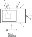
- a known alignment system 1 providing this functionality is schematically shown in FIG. 1 .
- the system 1 is shown from above, looking down onto the X-Y plane, the X, Y and Z axis directions being shown for clarity.
- a stencil support 2 is provided for supporting a stencil 3 thereon in the X-Y plane.
- the stencil is arranged to overlie a workpiece support 4, upon which a workpiece is supported in use.
- the relative positions, in the X-Y plane, of the stencil 3 and workpiece are optically determined by a camera system (not shown).
- three actuators are statically mounted on the printing machine to mechanically cooperate with the stencil support 2.
- Two alignment actuators 7, 8 act at lateral areas of the stencil support 2 to impel the stencil support 2 to move in the ⁇ X direction.
- the other alignment actuator 9 acts at a relatively central area of the stencil support 2 to impel the stencil support 2 to move in the ⁇ Y direction. It can be seen that if actuator 9 is activated on its own, the stencil support 2 will be translated along the Y axis, while it may be translated along the X axis if both actuators 7 and 8 are activated in tandem. Rotation of the stencil support 2, or combined rotation and translation, may be achieved by selectively activating a combination of actuators 7, 8 and 9. All of the alignment actuators 7, 8, 9 are held in fixed positions by mounting on the printing machine, for example on a static structure or frame of the printing machine.
- the print medium is applied to the workpiece through the stencil by depositing the medium onto the upper surface of the stencil and sweeping the squeegee across the upper surface in or parallel to the X-Y plane, forcing the print medium through the apertures of the stencil. Subsequently, the workpiece and stencil are separated.
- the present invention seeks to address this problem and achieve an improved multi-planar alignment (with three degrees of freedom) of printing stencils to workpieces within an industrial screen-printing machine.
- this aim is achieved by providing a planarity control mechanism effective to selectively rotate the stencil support about the X and Y axes so that the stencil is parallel, or at a predetermined angle, with the workpiece.
- a clamp assembly which is operable to permit rotation and translation of the stencil support during alignment and clamp the stencil support to prevent local movement along the X, Y and Z-axes when aligned.
- an alignment system for a workpiece printing machine as defined in claim 1 is provided.
- a method for printing a planar workpiece with a conductive medium as defined in claim 10 is also provided.
- FIG. 2 An alignment system 10 in accordance with an embodiment of the present invention is schematically shown in FIG. 2 .
- the alignment system 10 is adapted for mounting within a printing machine (not shown), the printing machine comprising a static supporting structure on which many components of the printing machine, including a workpiece support 4, are mounted.
- the alignment system 10 shown has many similarities with that of FIG. 1 , and so the same reference numerals are retained where appropriate.
- workpiece support 4 and a camera system for determining alignment in the X-Y plane are also present in the illustrated system.
- One difference is that the X-Y plane alignment actuators 7', 8', 9' are rearranged with respect to the set-up of FIG.
- a single alignment actuator 7' is positioned relatively centrally of a stencil support 14 to impel the stencil support 14 to move in the ⁇ X direction.
- the other two alignment actuators 8', 9' act at lateral areas of the stencil support 14 to impel the stencil support 14 to move in the ⁇ Y direction. It can be seen that if actuator 7' is activated on its own, the stencil support 14 will be translated, relative to the printing machine structure, along the X axis, while it may be translated along the Y axis if both actuators 8' and 9' are activated in tandem. Rotation of the stencil support 14, or combined rotation and translation, may be achieved by selectively activating a combination of actuators 7', 8' and 9'.
- a planarity control mechanism is further provided for enabling relative rotation of a stencil support 14, for supporting a stencil 3 in the X-Y plane, and the workpiece support 4, selectively about both the X and Y axes.
- the stencil support 14 is adapted to act as an alignment frame, so that it may be rotated selectively about the X and Y axes by means of three spaced alignment clamps 11, 12, 13 positioned around and incorporated into the stencil support 14.
- the structure of the printing machine is provided with respective lugs (see FIG. 5 ) projecting therefrom, which mechanically cooperate with respective alignment clamps 11, 12, 13 as will be described in more detail below.
- alignment clamps 11 and 12 are movable alignment clamps, capable of moving (i.e. lifting) the stencil support 14 with respect to the lugs to change the local distance along the Z-axis, while alignment clamp 13 is a fixed clamp, i.e. being incapable of effecting movement between the stencil support 14 and a lug, which acts as a pivot point.
- alignment clamp 13 may also be movable. Both fixed and movable alignment clamps are described in more detail below.
- a pair of front measurement sensors 5 and a pair of rear measurement sensors 6 are provided above the stencil support 14. These are effective to determine the position of a stencil mounted on the stencil support 14 in the Z-direction, as will be described in more detail below.
- the stencil support 14 acts as an alignment frame, while workpiece support 4 remains spatially fixed relative to the structure of the printing machine. It should be noted that in other embodiments (not shown), equally the workpiece support may be adapted to act as an alignment frame. In this case, the workpiece support may be aligned about the X and Y axes and clamped as required, while the stencil support remains spatially fixed with respect to the printing machine structure.
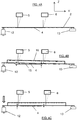
- FIGs. 3A-C schematically show a sequence of steps in a planarity alignment process for aligning the stencil 3 and workpiece using the apparatus of FIG. 2 , taken from a front view, i.e. looking along the positive Y direction.
- FIG. 4A-C schematically show this same sequence but taken from a side view, i.e. looking along the X direction.
- Comparison of FIGs. 3 and 4 therefore shows how orthogonal components of misalignment may be corrected.
- both FIGs. 3 and 4 omit the X and Y alignment actuators.
- alignment within the X-Y plane is achieved by these actuators in a similar way as is known in the prior art system shown in FIG. 1 .
- FIG. 3A and FIG. 4A show an initial step, in which no workpiece is yet loaded onto workpiece support 4, and no stencil is yet loaded onto stencil support 14.
- the alignment clamps 11, 12 and 13 are caused to be in a clamped state in which they clamp the stencil support 14 to hold it firmly in place with respect to the printing machine. Further details of the clamping mechanism are set out below.
- Workpiece support 4 the upper surface of which defines the X-Y plane, acts as a datum for an initial calibration measurement made by measurement sensors 5 and 6. Subsequent measurements may then be corrected based on the determined position of the workpiece support 4. It will be apparent to those skilled in the art that the measurement sensors 5 and 6 must be effective to measure distance, and there are a variety of techniques which may be utilised to achieve this.
- each measurement sensor is a laser device, which emits laser light downwardly and detects light reflected back.
- the present invention is not so limited however, and other measurement systems, such as ultrasonic or capacitive systems for example, may be used.
- FIG. 3B and FIG. 4B show a subsequent step in which a planar workpiece 15 has been loaded onto the workpiece support 4 so that it is supported in the X-Y plane, and a stencil 3 has been loaded into the stencil support 14.
- the stencil 3 is held under tension within a surrounding rectangular stencil frame 16, such as DEK's VectorGuard® frame system, with the frame contacting and resting on the stencil support 14.
- misalignment such as, for example, a foreign body stuck to the underside of the stencil frame 16, such as glue leaking through the stencil frame, or a damaged frame which has been caused to warp.
- a representative cause of misalignment is shown at 17, as being an arbitrary object located between the stencil frame 16 and stencil support 14.
- FIG. 3B a representative cause of misalignment is shown at 17, as being an arbitrary object located between the stencil frame 16 and stencil support 14.
- the alignment clamps 11, 12 and 13 are caused to switch to an unclamped state, in which the stencil support 14 is movable relative to the printing machine.
- FIG. 3C and FIG. 4C show a subsequent step following correction for misalignment.
- both alignment clamps 11 and 12 have been caused to move downwards (i.e. in the negative Z direction), so as to cause relative rotation of the stencil support 14 and workpiece support 4 about the X axis, with fixed alignment clamp 13 acting as a pivot point.
- This acts to correct the misalignment along the Y axis direction as determined by the measurement sensors 5, 6.
- alignment clamp 11 has been caused to move downwards more than alignment clamp 12, so as to cause relative rotation of the stencil support 14 and workpiece support 4 about the Y axis, and thus correct the misalignment along the X axis direction.
- the stencil 3 is caused to lie substantially parallel to the workpiece 15, ready for a subsequent printing process to be conducted.
- the measurement sensors 5, 6 may be used to obtain confirmation that the alignment of the workpiece 15 and stencil 3 are as required, and corrections made if necessary. Alignment within the X-Y plane may occur before, after or during this planarity alignment process.
- the alignment clamps 11, 12 and 13 are caused to be in a clamped state in which they clamp the stencil support 14 to hold it firmly in place with respect to the printing machine.
- the fixed alignment clamp 13 could be replaced with a movable alignment clamp, for example taking a similar form to alignment clamps 11 and 12.
- a movable alignment clamp for example taking a similar form to alignment clamps 11 and 12.
- Such an arrangement is equally able to effect relative rotation of the stencil support 14 and workpiece support 4 so as to effect the desired planarity alignment; in fact a greater degree of rotation is possible.
- such an arrangement has the benefit that the distance between stencil support 15 and workpiece support 4 in the Z direction may be adjusted as required.
- these benefits are at least partially offset by the resulting increase in apparatus complexity and additional space required.
- the optimum arrangement of stencil and workpiece might not be parallel.
- separation of the workpiece and stencil following a printing process may be effected in a controlled manner.
- the alignments could be set so that separation occurs from front to back (positive Y direction) or laterally (positive or negative X direction).
- the alignment may be adjusted during separation of the stencil and workpiece, so that printing may be performed with a parallel stencil and workpiece, but full control is obtained over the subsequent separation.
- FIG. 5 schematically shows a clamp assembly in the form of a movable alignment clamp 20 in accordance with an embodiment of the present invention.
- the alignment clamp 20 is arranged to clamp onto a portion of the printing machine structure.
- the structure is provided with a plurality of rigid projecting lugs 21, which structures are provided for mechanical cooperation with respective alignment clamps.
- Each projecting lug 21 takes the form of a plate lying in a plane parallel to the X-Y plane.
- An upper part of alignment clamp 20 is positioned above the lug 21, and a lower part of alignment clamp 20 is positioned below the lug 21, so as to be located in line with the upper part.
- the upper part includes a linear positioning or planarity actuator 22, the output of which is mechanically connected to a ball transfer bearing 23, which rests on the upper surface of lug 21 and also acts as an upper clamping surface.
- the planarity actuator 22 is operative to move the alignment frame, i.e. in this case the stencil support 14, relative to, and in reaction against, an external surface, in this case the upper surface of lug 21.
- the lower part includes a linear clamping actuator 24, the output of which is mechanically connected along a clamping axis to a frictional clamping element 25 via a linear guide 26.
- Frictional clamping element 25 is shown in this embodiment as a projection having a domed surface, however frictional clamping element 25 may alternatively comprise other forms of angularly compliant surface.
- the frictional clamping element 25 acts as a lower clamping surface. Use of an angularly compliant surface enables the lug 21 to be clamped at an inclined angle to the clamping axis.
- the alignment clamp 20 is incorporated into the stencil support 14, only a portion thereof being visible in FIG. 5 , so that the stencil support 14 acts as a yoke for the alignment clamp 20.
- Both the clamping actuator 24 and the planarity actuator 22 are controlled by a separate control means (not shown) such as a computer or processor, which is provided at or remote from the printing machine and adapted to receive measurement information from the front and rear measurement sensors 5, 6 (see FIG. 2 ).
- each alignment clamp is switched to an unclamped state.
- the ball transfer bearing 23 of each alignment clamp rests on a respective lug 21, on which it is free to roll, thus enabling the stencil support 14 to be aligned in the X-Y plane.
- the planarity of the stencil support 14 is aligned by operating the planarity actuator 22 to raise or lower the stencil support 14 along the Z axis until the required position is reached, as determined by the control means in dependence on the output received from the measurement sensors. Clamping of the stencil support 14 is then effected by switching to a clamped state.
- the clamping actuator 24 is operated to move the frictional clamping element 25 upwardly along a clamping axis which is normal to the plane of the stencil support 14, this movement being guided by the linear guide 26. The upward movement is continued until the lug 21 is firmly clamped between the frictional clamping element 25 and ball transfer bearing 23.
- FIG. 6 schematically shows a fixed alignment clamp 30 in accordance with a further embodiment of the present invention.
- This alignment clamp 30 has many parts in common with the movable alignment clamp 20 of FIG. 5 , and the reference numerals have been retained where appropriate.
- the lower part of fixed alignment clamp 30 is identical to that of movable alignment clamp 20.
- the ball transfer bearing 23 is mounted on a static nut 31.
- FIG. 7 schematically shows a movable alignment clamp 40 in accordance with another embodiment of the present invention.
- This alignment clamp 40 has many parts in common with the movable alignment clamp 20 of FIG. 5 , and the reference numerals have been retained where appropriate.
- the alignment clamp 40 differs from previously-described alignment clamp 20 in that here the frictional clamping element 25 is replaced by a rotatable element in the form of a ball joint 41, which carries a foot 42 with frictional material provided thereon.
- This alignment clamp 40 is operated in an identical fashion to alignment 20 as described above.
- FIG. 8 schematically shows a movable alignment clamp 50 in accordance with a further embodiment of the present invention.
- This alignment clamp 50 has many parts in common with the movable alignment clamp 20 of FIG. 5 , and the reference numerals have been retained where appropriate. For clarity, the stencil support 14 is omitted from the figure.
- the clamping actuator 24 is arranged to act directly on the lower surface of lug 21. To assist with clamping, frictional material may be applied to the upper mating face of clamping actuator 24.
- the upper part of alignment clamp 50 comprises an air bearing 51 which is mounted via a swivelling element, i.e. a swivel joint 52 to the planarity actuator 22.
- a linear guide 53 is provided to guide the air bearing 51 and swivel joint 52 arrangement, to accurately lift the stencil support during operation.
- frictional material may be applied to the lower mating face of air bearing 51.
- the alignment clamp 50 Operation of the alignment clamp 50 is identical to that previously described with reference to FIGs. 5 and 7 . It should be noted that while in this embodiment the upper part of the alignment clamp 50 does not include either a frictional clamping element or a ball joint, the low friction provided by air bearing 51 permits the necessary movement.
- FIG. 9 schematically shows a movable alignment clamp 60 in accordance with another embodiment of the present invention.
- This alignment clamp 60 has many parts in common with the movable alignment clamp 50 of FIG. 8 , and the reference numerals have been retained where appropriate.
- the stencil support 14 is omitted from the figure.
- the linear guide 53 of alignment clamp 50 is replaced by the use of a precision guide 61, which mechanically connects the swivel joint 52 and planarity actuator 22.
- the precision guide 61 which may for example comprise a ball spline, accurately guides the movement of air bearing 51 without the need for an external guide structure.
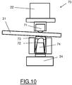
- FIG. 10 schematically shows a movable alignment clamp 70 in accordance with a yet further embodiment of the present invention.
- the lug 21 is shown in a rotated state.
- This alignment clamp 70 has many parts in common with the movable alignment clamp 20 of FIG. 5 , and the reference numerals have been retained where appropriate.
- the stencil support 14 is omitted from the figure.
- the upper part of alignment clamp 70 comprises a ball transfer bearing 71 mechanically connected to the output of planarity actuator 22.
- the lower part of alignment clamp 70 includes a rotatable element in the form of a collet arrangement in order to enable rotation of the lug 21.
- the clamping actuator 24 is mechanically connected to a collet expander 74, which takes the form of a frustoconical projection. This cooperates with a swivel collet 72, which takes the form of a cylinder having a frustoconical recess which is sized so as to receive the collet expander 74 while permitting relative movement therebetween.
- the swivel collet 72 carries at its distal end a friction plate 73, which contacts the lower surface of the lug 21 in use.
- the above-described embodiments are exemplary only, and other possibilities and alternatives within the scope of the invention will be apparent to those skilled in the art.
- the above-described embodiments show the clamping actuator located below the stencil support, with the planarity actuator located above the stencil support. It will be apparent to those skilled in the art that this arrangement could be inverted, so that the planarity actuator is located below the stencil support and the clamping actuator located above.
- linear actuators Other forms of actuator which result in movement along the Z-axis may alternatively be used.
- a "Z-lift" arrangement in which horizontal movement is translated into vertical movement either using a cam arrangement or a wedge, scissor mechanism or electric drive as is known in the art, may replace a linear actuator.
- the linearity of the actuator movement is not essential as long as a component of movement in the Z-direction is produced, and so a linear actuator may instead be driven through a curved bearing.
- the above-described embodiments disclose alignment systems in which a plurality of alignment clamps, each including a planarity actuator, are provided, which are spaced around the alignment frame.
- the alignment frame comprises the stencil support.
- the alignment frame could comprise the workpiece support, to provide relative rotation of the stencil support and workpiece support.
- each measurement sensor may be mounted on a gantry which may move over and relative to the workpiece support.
- the printing machine is calibrated by measuring a reference position of the workpiece support, so that this is used as a datum.
- a reference position of the workpiece may be measured and used in this way.
Landscapes
- Engineering & Computer Science (AREA)
- Mechanical Engineering (AREA)
- General Engineering & Computer Science (AREA)
- Manufacturing & Machinery (AREA)
- Microelectronics & Electronic Packaging (AREA)
- Screen Printers (AREA)
- Electric Connection Of Electric Components To Printed Circuits (AREA)
- Printing Methods (AREA)
Description
- This invention relates to an alignment system, a printing machine and a method for printing a planar workpiece.
- Industrial screen-printing machines typically apply print media, such as solder paste or conductive ink, onto a planar workpiece, such as a circuit board, by applying a medium (e.g. solder paste) through a stencil using an angled blade or squeegee. To ensure that the stencil aligns correctly with the workpiece, the relative position of markers provided on the stencil and workpiece, in the plane of the workpiece (which is conventionally denoted the X-Y plane and is generally horizontal), are measured and subsequently aligned. One or more cameras may be used to optically measure the positions of the markings.
- Typically, the stencil and workpiece are then aligned in the X-Y plane by means of actuators which act on a stencil support to move the stencil supported thereon relative to the workpiece. The extent of movement required is determined by the preceding optical measurement. Such alignment normally occurs over the single X-Y plane, using two degrees of freedom. Subsequently, the stencil is brought into contact (or near contact) with the workpiece, by effecting relative movement between the stencil and workpiece in a direction normal to the workpiece (conventionally denoted as movement along the Z-axis).
- A known alignment system 1 providing this functionality is schematically shown in
FIG. 1 . Here the system 1 is shown from above, looking down onto the X-Y plane, the X, Y and Z axis directions being shown for clarity. Astencil support 2 is provided for supporting astencil 3 thereon in the X-Y plane. The stencil is arranged to overlie aworkpiece support 4, upon which a workpiece is supported in use. The relative positions, in the X-Y plane, of thestencil 3 and workpiece are optically determined by a camera system (not shown). In order for the stencil support to be moved both translationally and rotationally in the X-Y plane, and relative to the printing machine, three actuators are statically mounted on the printing machine to mechanically cooperate with thestencil support 2. Twoalignment actuators stencil support 2 to impel thestencil support 2 to move in the ± X direction. Theother alignment actuator 9 acts at a relatively central area of thestencil support 2 to impel thestencil support 2 to move in the ± Y direction. It can be seen that ifactuator 9 is activated on its own, thestencil support 2 will be translated along the Y axis, while it may be translated along the X axis if bothactuators stencil support 2, or combined rotation and translation, may be achieved by selectively activating a combination ofactuators alignment actuators - While in this system the stencil support is actuated to move relative to the workpiece support, in other systems actuators may act directly on the workpiece support to achieve relative movement.
- After alignment, the print medium is applied to the workpiece through the stencil by depositing the medium onto the upper surface of the stencil and sweeping the squeegee across the upper surface in or parallel to the X-Y plane, forcing the print medium through the apertures of the stencil. Subsequently, the workpiece and stencil are separated.
- It has been found through extensive research that control of the angle of separation between the stencil and workpiece is crucial to controlling print quality. Documents
WO2012/119904 A1 andDE102011005158 A1 respectively disclose an alignment system for a workpiece printing machine according to the preamble of claim 1. However, these known printing machines do not provide a reliable automatic correction for planar alignment errors. - The present invention seeks to address this problem and achieve an improved multi-planar alignment (with three degrees of freedom) of printing stencils to workpieces within an industrial screen-printing machine.
- In accordance with the present invention this aim is achieved by providing a planarity control mechanism effective to selectively rotate the stencil support about the X and Y axes so that the stencil is parallel, or at a predetermined angle, with the workpiece.
- This aim is also achieved in accordance with an embodiment of the present invention by the provision of a clamp assembly which is operable to permit rotation and translation of the stencil support during alignment and clamp the stencil support to prevent local movement along the X, Y and Z-axes when aligned.
- In accordance with a first aspect of the present invention an alignment system for a workpiece printing machine as defined in claim 1 is provided.
- In accordance with a second aspect of the present invention a method for printing a planar workpiece with a conductive medium as defined in
claim 10 is also provided. - Further preferred embodiments of the present invention are set out in the dependent claims 2-9.
- The invention will now be described with reference to the accompanying drawings (not to scale), in which:
-
FIG. 1 schematically shows a known alignment system from above; -
FIG. 2 schematically shows an alignment system in accordance with an embodiment of the present invention from above; -
FIGs. 3A-C schematically show a sequence of steps in a planarity alignment process in accordance with the present invention from a front view looking along a positive Y direction; -
FIGs. 4A-C schematically show the sequence of steps ofFIGs. 3A-C from a side view looking along an X-direction; -
FIG. 5 schematically shows a movable alignment clamp in accordance with an embodiment of the present invention; -
FIG. 6 schematically shows a fixed alignment clamp in accordance with a further embodiment of the present invention; -
FIG. 7 schematically shows a movable alignment clamp in accordance with another embodiment of the present invention; -
FIG. 8 schematically shows a movable alignment clamp in accordance with a further embodiment of the present invention; -
FIG. 9 schematically shows a movable alignment clamp in accordance with another embodiment of the present invention; and -
FIG. 10 schematically shows a movable alignment clamp in accordance with a yet further embodiment of the present invention. - An
alignment system 10 in accordance with an embodiment of the present invention is schematically shown inFIG. 2 . Thealignment system 10 is adapted for mounting within a printing machine (not shown), the printing machine comprising a static supporting structure on which many components of the printing machine, including aworkpiece support 4, are mounted. Thealignment system 10 shown has many similarities with that ofFIG. 1 , and so the same reference numerals are retained where appropriate. In particular,workpiece support 4 and a camera system for determining alignment in the X-Y plane are also present in the illustrated system. One difference is that the X-Y plane alignment actuators 7', 8', 9' are rearranged with respect to the set-up ofFIG. 1 , so that a single alignment actuator 7' is positioned relatively centrally of astencil support 14 to impel thestencil support 14 to move in the ± X direction. The other two alignment actuators 8', 9' act at lateral areas of thestencil support 14 to impel thestencil support 14 to move in the ± Y direction. It can be seen that if actuator 7' is activated on its own, thestencil support 14 will be translated, relative to the printing machine structure, along the X axis, while it may be translated along the Y axis if both actuators 8' and 9' are activated in tandem. Rotation of thestencil support 14, or combined rotation and translation, may be achieved by selectively activating a combination of actuators 7', 8' and 9'. - With the
present alignment system 10, a planarity control mechanism is further provided for enabling relative rotation of astencil support 14, for supporting astencil 3 in the X-Y plane, and theworkpiece support 4, selectively about both the X and Y axes. In this embodiment, thestencil support 14 is adapted to act as an alignment frame, so that it may be rotated selectively about the X and Y axes by means of three spacedalignment clamps stencil support 14. To this end, the structure of the printing machine is provided with respective lugs (seeFIG. 5 ) projecting therefrom, which mechanically cooperate withrespective alignment clamps alignment clamps stencil support 14 with respect to the lugs to change the local distance along the Z-axis, whilealignment clamp 13 is a fixed clamp, i.e. being incapable of effecting movement between thestencil support 14 and a lug, which acts as a pivot point. In other embodiments,alignment clamp 13 may also be movable. Both fixed and movable alignment clamps are described in more detail below. - A pair of
front measurement sensors 5 and a pair ofrear measurement sensors 6 are provided above thestencil support 14. These are effective to determine the position of a stencil mounted on thestencil support 14 in the Z-direction, as will be described in more detail below. - As noted above, in this embodiment, the
stencil support 14 acts as an alignment frame, whileworkpiece support 4 remains spatially fixed relative to the structure of the printing machine. It should be noted that in other embodiments (not shown), equally the workpiece support may be adapted to act as an alignment frame. In this case, the workpiece support may be aligned about the X and Y axes and clamped as required, while the stencil support remains spatially fixed with respect to the printing machine structure. -
FIGs. 3A-C schematically show a sequence of steps in a planarity alignment process for aligning thestencil 3 and workpiece using the apparatus ofFIG. 2 , taken from a front view, i.e. looking along the positive Y direction. Similarly,FIG. 4A-C schematically show this same sequence but taken from a side view, i.e. looking along the X direction. Comparison ofFIGs. 3 and4 therefore shows how orthogonal components of misalignment may be corrected. For clarity, bothFIGs. 3 and4 omit the X and Y alignment actuators. For the avoidance of doubt, alignment within the X-Y plane is achieved by these actuators in a similar way as is known in the prior art system shown inFIG. 1 . -
FIG. 3A andFIG. 4A show an initial step, in which no workpiece is yet loaded ontoworkpiece support 4, and no stencil is yet loaded ontostencil support 14. The alignment clamps 11, 12 and 13 are caused to be in a clamped state in which they clamp thestencil support 14 to hold it firmly in place with respect to the printing machine. Further details of the clamping mechanism are set out below.Workpiece support 4, the upper surface of which defines the X-Y plane, acts as a datum for an initial calibration measurement made bymeasurement sensors workpiece support 4. It will be apparent to those skilled in the art that themeasurement sensors FIGs. 3 and4 , each measurement sensor is a laser device, which emits laser light downwardly and detects light reflected back. The present invention is not so limited however, and other measurement systems, such as ultrasonic or capacitive systems for example, may be used. -
FIG. 3B andFIG. 4B show a subsequent step in which aplanar workpiece 15 has been loaded onto theworkpiece support 4 so that it is supported in the X-Y plane, and astencil 3 has been loaded into thestencil support 14. In practice, and as is well-known in the art, thestencil 3 is held under tension within a surroundingrectangular stencil frame 16, such as DEK's VectorGuard® frame system, with the frame contacting and resting on thestencil support 14. - It can be seen from
FIG. 3B that in this example thestencil 3 is misaligned with theworkpiece 15 along the X direction, i.e. at a position X=0 the distance between thestencil 3 andworkpiece 15 is smaller than at a distance X=n (n>0). There could be various causes of such misalignment, such as, for example, a foreign body stuck to the underside of thestencil frame 16, such as glue leaking through the stencil frame, or a damaged frame which has been caused to warp. InFIG. 3B , a representative cause of misalignment is shown at 17, as being an arbitrary object located between thestencil frame 16 andstencil support 14. Similarly,FIG. 4B shows that in this example thestencil 3 is misaligned with theworkpiece 15 along the Y direction, i.e. at a position Y=0 the distance between thestencil 3 andworkpiece 15 is greater than at a distance Y=n (n>0). In this case therefore, the maximum misalignment occurs in the vicinity ofalignment clamp 11. The extent of misalignment is determined by comparing the measurements taken by front andrear measurement sensors measurement sensors stencil 3 with respect to both the X and Y axes can be determined. - In order to perform correction for misalignment, the alignment clamps 11, 12 and 13 are caused to switch to an unclamped state, in which the
stencil support 14 is movable relative to the printing machine. -
FIG. 3C andFIG. 4C show a subsequent step following correction for misalignment. As can be seen, in this case both alignment clamps 11 and 12 have been caused to move downwards (i.e. in the negative Z direction), so as to cause relative rotation of thestencil support 14 andworkpiece support 4 about the X axis, with fixedalignment clamp 13 acting as a pivot point. This acts to correct the misalignment along the Y axis direction as determined by themeasurement sensors alignment clamp 11 has been caused to move downwards more thanalignment clamp 12, so as to cause relative rotation of thestencil support 14 andworkpiece support 4 about the Y axis, and thus correct the misalignment along the X axis direction. Following correction, in this case thestencil 3 is caused to lie substantially parallel to theworkpiece 15, ready for a subsequent printing process to be conducted. Themeasurement sensors workpiece 15 andstencil 3 are as required, and corrections made if necessary. Alignment within the X-Y plane may occur before, after or during this planarity alignment process. Following all alignment steps, the alignment clamps 11, 12 and 13 are caused to be in a clamped state in which they clamp thestencil support 14 to hold it firmly in place with respect to the printing machine. - As noted above, in some embodiments (not shown) the fixed
alignment clamp 13 could be replaced with a movable alignment clamp, for example taking a similar form to alignment clamps 11 and 12. Such an arrangement is equally able to effect relative rotation of thestencil support 14 andworkpiece support 4 so as to effect the desired planarity alignment; in fact a greater degree of rotation is possible. In addition, such an arrangement has the benefit that the distance betweenstencil support 15 andworkpiece support 4 in the Z direction may be adjusted as required. However, these benefits are at least partially offset by the resulting increase in apparatus complexity and additional space required. - It should be noted that in some instances the optimum arrangement of stencil and workpiece might not be parallel. For example, by setting the stencil and workpiece planes to be slightly off-parallel, separation of the workpiece and stencil following a printing process may be effected in a controlled manner. As specific examples, the alignments could be set so that separation occurs from front to back (positive Y direction) or laterally (positive or negative X direction). Furthermore, the alignment may be adjusted during separation of the stencil and workpiece, so that printing may be performed with a parallel stencil and workpiece, but full control is obtained over the subsequent separation.
- Those skilled in the art will appreciate from the above description that the alignment clamps 11, 12 and 13 perform three functions:
- i) to permit the alignment frame (in this embodiment the stencil support 14) to move freely in the X-Y plane during X-Y alignment, i.e. while the alignment clamps 11, 12 and 13 are in an unclamped state;
- ii) to act on the alignment frame to cause selective rotation of the alignment frame about the X and Y axes while in the unclamped state; and
- iii) to effect a clamped state in which the
stencil support 14 is clamped firmly when it is aligned as required with respect to all axes. -
FIG. 5 schematically shows a clamp assembly in the form of amovable alignment clamp 20 in accordance with an embodiment of the present invention. Thealignment clamp 20 is arranged to clamp onto a portion of the printing machine structure. As shown, the structure is provided with a plurality of rigid projectinglugs 21, which structures are provided for mechanical cooperation with respective alignment clamps. Each projectinglug 21 takes the form of a plate lying in a plane parallel to the X-Y plane. An upper part ofalignment clamp 20 is positioned above thelug 21, and a lower part ofalignment clamp 20 is positioned below thelug 21, so as to be located in line with the upper part. The upper part includes a linear positioning orplanarity actuator 22, the output of which is mechanically connected to a ball transfer bearing 23, which rests on the upper surface oflug 21 and also acts as an upper clamping surface. Theplanarity actuator 22 is operative to move the alignment frame, i.e. in this case thestencil support 14, relative to, and in reaction against, an external surface, in this case the upper surface oflug 21. The lower part includes alinear clamping actuator 24, the output of which is mechanically connected along a clamping axis to africtional clamping element 25 via alinear guide 26.Frictional clamping element 25 is shown in this embodiment as a projection having a domed surface, howeverfrictional clamping element 25 may alternatively comprise other forms of angularly compliant surface. Thefrictional clamping element 25 acts as a lower clamping surface. Use of an angularly compliant surface enables thelug 21 to be clamped at an inclined angle to the clamping axis. - In this embodiment, the
alignment clamp 20 is incorporated into thestencil support 14, only a portion thereof being visible inFIG. 5 , so that thestencil support 14 acts as a yoke for thealignment clamp 20. Both the clampingactuator 24 and theplanarity actuator 22 are controlled by a separate control means (not shown) such as a computer or processor, which is provided at or remote from the printing machine and adapted to receive measurement information from the front andrear measurement sensors 5, 6 (seeFIG. 2 ). - During alignment, when the
stencil support 14 is loaded into the printing machine, each alignment clamp is switched to an unclamped state. In this state, the ball transfer bearing 23 of each alignment clamp rests on arespective lug 21, on which it is free to roll, thus enabling thestencil support 14 to be aligned in the X-Y plane. The planarity of thestencil support 14 is aligned by operating theplanarity actuator 22 to raise or lower thestencil support 14 along the Z axis until the required position is reached, as determined by the control means in dependence on the output received from the measurement sensors. Clamping of thestencil support 14 is then effected by switching to a clamped state. To effect this, the clampingactuator 24 is operated to move thefrictional clamping element 25 upwardly along a clamping axis which is normal to the plane of thestencil support 14, this movement being guided by thelinear guide 26. The upward movement is continued until thelug 21 is firmly clamped between thefrictional clamping element 25 and ball transfer bearing 23. -
FIG. 6 schematically shows a fixedalignment clamp 30 in accordance with a further embodiment of the present invention. Thisalignment clamp 30 has many parts in common with themovable alignment clamp 20 ofFIG. 5 , and the reference numerals have been retained where appropriate. The lower part of fixedalignment clamp 30 is identical to that ofmovable alignment clamp 20. Here though there is no planarity actuator provided - instead, the ball transfer bearing 23 is mounted on astatic nut 31. - With this fixed
alignment clamp 30, clamping is effected in the same manner as formovable alignment clamp 20, so that the clampingactuator 24 is operated to cause thelug 21 to be clamped between frictional clampingelement 25 and ball transfer bearing 23. With this arrangement the fixedalignment clamp 30 effectively acts as a pivot point for thestencil support 14. -
FIG. 7 schematically shows amovable alignment clamp 40 in accordance with another embodiment of the present invention. Thisalignment clamp 40 has many parts in common with themovable alignment clamp 20 ofFIG. 5 , and the reference numerals have been retained where appropriate. Thealignment clamp 40 differs from previously-describedalignment clamp 20 in that here thefrictional clamping element 25 is replaced by a rotatable element in the form of a ball joint 41, which carries afoot 42 with frictional material provided thereon. Thisalignment clamp 40 is operated in an identical fashion toalignment 20 as described above. -
FIG. 8 schematically shows amovable alignment clamp 50 in accordance with a further embodiment of the present invention. Thisalignment clamp 50 has many parts in common with themovable alignment clamp 20 ofFIG. 5 , and the reference numerals have been retained where appropriate. For clarity, thestencil support 14 is omitted from the figure. With thisalignment clamp 50, the clampingactuator 24 is arranged to act directly on the lower surface oflug 21. To assist with clamping, frictional material may be applied to the upper mating face of clampingactuator 24. The upper part ofalignment clamp 50 comprises anair bearing 51 which is mounted via a swivelling element, i.e. a swivel joint 52 to theplanarity actuator 22. Alinear guide 53 is provided to guide theair bearing 51 and swivel joint 52 arrangement, to accurately lift the stencil support during operation. To assist with clamping, frictional material may be applied to the lower mating face ofair bearing 51. Use of such a swivel mounting enables the lug to be clamped along the clamping axis to be held at an inclined angle to the clamping axis. - Operation of the
alignment clamp 50 is identical to that previously described with reference toFIGs. 5 and7 . It should be noted that while in this embodiment the upper part of thealignment clamp 50 does not include either a frictional clamping element or a ball joint, the low friction provided by air bearing 51 permits the necessary movement. -
FIG. 9 schematically shows amovable alignment clamp 60 in accordance with another embodiment of the present invention. Thisalignment clamp 60 has many parts in common with themovable alignment clamp 50 ofFIG. 8 , and the reference numerals have been retained where appropriate. For clarity, thestencil support 14 is omitted from the figure. In this embodiment, thelinear guide 53 ofalignment clamp 50 is replaced by the use of aprecision guide 61, which mechanically connects the swivel joint 52 andplanarity actuator 22. Theprecision guide 61, which may for example comprise a ball spline, accurately guides the movement ofair bearing 51 without the need for an external guide structure. -
FIG. 10 schematically shows amovable alignment clamp 70 in accordance with a yet further embodiment of the present invention. InFIG. 10 it should be noted that thelug 21 is shown in a rotated state. Thisalignment clamp 70 has many parts in common with themovable alignment clamp 20 ofFIG. 5 , and the reference numerals have been retained where appropriate. For clarity, thestencil support 14 is omitted from the figure. The upper part ofalignment clamp 70 comprises a ball transfer bearing 71 mechanically connected to the output ofplanarity actuator 22. The lower part ofalignment clamp 70 includes a rotatable element in the form of a collet arrangement in order to enable rotation of thelug 21. The clampingactuator 24 is mechanically connected to acollet expander 74, which takes the form of a frustoconical projection. This cooperates with aswivel collet 72, which takes the form of a cylinder having a frustoconical recess which is sized so as to receive thecollet expander 74 while permitting relative movement therebetween. Theswivel collet 72 carries at its distal end afriction plate 73, which contacts the lower surface of thelug 21 in use. - The above-described embodiments are exemplary only, and other possibilities and alternatives within the scope of the invention will be apparent to those skilled in the art. For example, the above-described embodiments show the clamping actuator located below the stencil support, with the planarity actuator located above the stencil support. It will be apparent to those skilled in the art that this arrangement could be inverted, so that the planarity actuator is located below the stencil support and the clamping actuator located above.
- The above-described embodiments disclose the use of linear actuators. Other forms of actuator which result in movement along the Z-axis may alternatively be used. For example, a "Z-lift" arrangement, in which horizontal movement is translated into vertical movement either using a cam arrangement or a wedge, scissor mechanism or electric drive as is known in the art, may replace a linear actuator.
- The linearity of the actuator movement is not essential as long as a component of movement in the Z-direction is produced, and so a linear actuator may instead be driven through a curved bearing.
- The above-described embodiments disclose alignment systems in which a plurality of alignment clamps, each including a planarity actuator, are provided, which are spaced around the alignment frame.
- As previously suggested, in the specific embodiments described above, the alignment frame comprises the stencil support. Equally however, the alignment frame could comprise the workpiece support, to provide relative rotation of the stencil support and workpiece support.
- Instead of four measurement sensors, could use one or two movable sensors which take a reading in a first position, then move to a second position and take a second measurement. In such embodiments each measurement sensor may be mounted on a gantry which may move over and relative to the workpiece support.
- In the above-described embodiments, the printing machine is calibrated by measuring a reference position of the workpiece support, so that this is used as a datum. Alternatively, a reference position of the workpiece may be measured and used in this way.
-
- 1 - Known alignment system
- 2 - Stencil support
- 3 - Stencil
- 4 - Workpiece support
- 5 - Front measurement sensors
- 6 - Rear measurement sensors
- 7, 8 - X alignment actuators
- 9 - Y alignment actuator
- 7' - X alignment actuator
- 8', 9' - Y alignment actuators
- 10 - Alignment system
- 11, 12, 13 - Z alignment clamps
- 14 - Stencil support
- 15 - Workpiece
- 16 - Stencil frame
- 17 - Misalignment cause
- 20, 40, 50, 60, 70 - Movable alignment clamp
- 21 - Lug
- 22 - Planarity actuator
- 23 - Ball transfer bearing
- 24 - Clamping actuator
- 25 - Frictional clamping element
- 26 - Linear guide
- 30 - Fixed alignment clamp
- 31 - Static nut
- 41 - Ball joint
- 51 - Air bearing
- 52 - Swivel joint
- 53 - Linear guide
- 54 - Frictional material
- 61 - Precision guide
- 71- Ball transfer bearing
- 72 - Swivel collet
- 73 - Friction plate
- 74 - Collet expander
Claims (10)
- An alignment system (10) for a workpiece printing machine, comprising:a stencil support (14) for supporting a substantially planar stencil (3) in use,a workpiece support (4) for supporting a planar workpiece (15) in an X-Y plane in use, the X-Y plane being defined as that plane which includes orthogonal X and Y axes,a planarity control mechanism comprising at least two actuators (22) arranged to effect relative rotation of the stencil support (14) and workpiece support (4) about both the X and the Y axis,characterised in that the alignment system (10) comprises first and second movable alignment clamps (20, 40, 50, 60, 70), each of the first and second movable alignment clamps (20, 40, 50, 60, 70) comprising a respective one of said at least two actuators (22), which is located at respective first and second spaced locations on an alignment frame.
- The alignment system of claim 1, comprising a fixed alignment clamp (30) located at a third location on the alignment frame, such that the fixed alignment clamp (30) acts as a pivot for the alignment frame.
- The alignment system of claim 1, comprising a third movable alignment clamp (20, 40, 50, 60, 70) located at a third location on the alignment frame.
- The alignment system of any of the claims 1 to 3, further comprising an X-Y alignment mechanism in mechanical cooperation with the alignment frame for moving the alignment frame within the X-Y plane.
- The alignment system of claim 4 when dependent on any of the claims 2 to 3, wherein each fixed (30) or movable alignment clamp (20, 40, 50, 60, 70) comprises a respective bearing (23, 51, 71), said fixed (30) or movable alignment clamp (20, 40, 50, 60, 70) in use mechanically cooperating with a respective external surface via said respective bearing (23, 51, 71) to enable movement of the alignment frame in the X-Y plane; optionally each actuator (22) is operative to move the alignment frame relative to, and in reaction against, the respective external surface; optionally each fixed (30) or movable alignment clamp (20, 40, 50, 60, 70) comprises a clamping actuator (24) operable to clamp said fixed (30) or movable alignment clamp (20, 40, 50, 60, 70) to the respective external surface.
- The alignment system of any of the claims 1 to 5, wherein the alignment frame comprises either the stencil support (14) or the workpiece support (4).
- The alignment system of claim 5, wherein the planarity control mechanism comprises a clamp assembly, the clamp assembly comprising:first and second mutually opposed clamping surfaces for clamping a rigid structure therebetween, the first clamping surface is mounted on said clamping actuator (24) operative to switch the clamp assembly between a first, unclamped state and a second, clamped state in which clamped state said rigid structure is clamped between the first and second clamping surfaces,said switching being effected by the clamping actuator (24) moving the first clamping surface along a clamping axis towards the second clamping surface, anda positioning actuator, optionally a linear actuator, mechanically connected to the second clamping surface, for moving part of the clamp assembly relative to the second clamping surface, along the clamping axis; optionally the clamp assembly comprises a curved bearing and a linear actuator for driving the curved bearing in use,wherein at least one of the first and second clamping surfaces comprises a bearing (23, 51, 71), such that the rigid structure is movable relative to said clamping surface via said bearing (23, 51, 71) when the clamp assembly is in the first, unclamped state, the positioning actuator of the clamp assembly being arranged to effect rotation of the alignment frame.
- The alignment system of claim 7, wherein one of the first and second clamping surfaces comprises a bearing (23, 51, 71), and the other one of the first and second clamping surfaces comprises a domed or swivelling frictional element, such that the rigid structure may be clamped along the clamping axis to be held at an inclined angle to the clamping axis.
- A printing machine comprising the alignment system of any of the claims 1 to 8; optionally comprising a supporting structure, the supporting structure comprising a plurality of lugs (21) projecting therefrom, and the planarity control mechanism mechanically cooperates with the supporting structure via said lugs (21); the printing machine optionally further comprising a sensor arrangement for measuring the distance of a plurality of points of the stencil (3) relative to the X-Y plane, when the stencil (3) is supported by the stencil support (14).
- A method for printing a planar workpiece with a conductive medium, comprising the steps of:i) providing a printing machine in accordance with claim 9,ii) loading a substantially planar stencil (3) into the stencil support (14),iii) measuring the distance of a plurality of points of the substantially planar stencil (3) relative to the X-Y plane,iv) rotating the stencil support (14) relative to the workpiece support (4) about at least one of the X and Y axes until the substantially planar stencil (3) is at a required orientation to the X-Y plane,v) loading a workpiece onto the workpiece support (4) such that it is located below the substantially planar stencil (3), andvi) printing conductive medium onto the workpiece via the substantially planar stencil (3).
Applications Claiming Priority (1)
| Application Number | Priority Date | Filing Date | Title |
|---|---|---|---|
| GB1718374.0A GB2568243A (en) | 2017-11-07 | 2017-11-07 | Planarity alignment of stencils and workpieces |
Publications (2)
| Publication Number | Publication Date |
|---|---|
| EP3480015A1 EP3480015A1 (en) | 2019-05-08 |
| EP3480015B1 true EP3480015B1 (en) | 2021-03-24 |
Family
ID=60664680
Family Applications (1)
| Application Number | Title | Priority Date | Filing Date |
|---|---|---|---|
| EP18020493.5A Active EP3480015B1 (en) | 2017-11-07 | 2018-10-11 | Planarity alignment of stencils and workpieces |
Country Status (7)
| Country | Link |
|---|---|
| US (1) | US10994527B2 (en) |
| EP (1) | EP3480015B1 (en) |
| JP (1) | JP6876667B2 (en) |
| KR (1) | KR102215683B1 (en) |
| CN (1) | CN109910426B (en) |
| GB (1) | GB2568243A (en) |
| TW (1) | TWI676782B (en) |
Families Citing this family (5)
| Publication number | Priority date | Publication date | Assignee | Title |
|---|---|---|---|---|
| CN108944005B (en) * | 2018-09-19 | 2023-12-15 | 宁波工程学院 | Alignment fixture and alignment method for screen printing preparation of sheet type oxygen sensor |
| TWI707740B (en) | 2019-11-26 | 2020-10-21 | 財團法人工業技術研究院 | Adjustable workpiece support system and method |
| KR20230067210A (en) * | 2021-11-09 | 2023-05-16 | 한화정밀기계 주식회사 | Planarization inspecting method of screen printer |
| KR102833134B1 (en) * | 2022-07-08 | 2025-07-11 | 주식회사 엠플러스 | Pouch position adjustment system for secondary battery manufacturing forming line |
| CN115930885B (en) * | 2022-12-07 | 2023-07-28 | 广州锋明智能科技有限公司 | Workbench flatness detection device for PCB equipment manufacturing |
Family Cites Families (29)
| Publication number | Priority date | Publication date | Assignee | Title |
|---|---|---|---|---|
| US4254707A (en) * | 1979-05-02 | 1981-03-10 | Itron, Inc. | Screen printing apparatus with screen peel-off from work |
| FR2627431A1 (en) * | 1988-02-19 | 1989-08-25 | Radiotechnique Compelec | MACHINE OF SERIGRAPHY |
| DE69120256T2 (en) * | 1990-02-09 | 1997-01-30 | Wilfried 51373 Leverkusen Lichtenberg | TENSION CLAMP WITH ROTATING AND SLIDING JAWS |
| GB9102850D0 (en) * | 1991-02-11 | 1991-03-27 | Dek Printing Machines Ltd | Workpiece support means |
| DE4240003C2 (en) * | 1992-11-27 | 1997-11-20 | Herhof Umwelttechnik Gmbh | Screw clamp |
| JPH09109363A (en) * | 1995-10-19 | 1997-04-28 | Tokyo Process Service Kk | Metal printing plate |
| US6065399A (en) * | 1998-10-20 | 2000-05-23 | Reefdale Proprietary Limited | Screen printing machines |
| GB2351258A (en) * | 1999-06-22 | 2000-12-27 | Blakell Europlacer Ltd | Apparatus and method for aligning two objects |
| US6490971B2 (en) * | 2001-02-16 | 2002-12-10 | Steven S. Rosenberg | Apparatus and method for framing a printing screen |
| JP2003291301A (en) * | 2002-04-05 | 2003-10-14 | Murata Mfg Co Ltd | Screen printing method |
| JP3858009B2 (en) * | 2003-07-31 | 2006-12-13 | Tdk株式会社 | Screen printing machine |
| ITMI20050499A1 (en) * | 2005-03-24 | 2006-09-25 | Siasprint S R L | MACHINE AND METHOD FOR SERIGRAPHIC PRINTING |
| JP2007105825A (en) * | 2005-10-13 | 2007-04-26 | Honda Motor Co Ltd | Clamping jig |
| JP2007160659A (en) * | 2005-12-13 | 2007-06-28 | Matsushita Electric Ind Co Ltd | Screen printing apparatus and screen printing method |
| US8104752B2 (en) * | 2006-03-20 | 2012-01-31 | Boaz Eidelberg | Integrated large XY rotary positioning table with virtual center of rotation |
| JP5080148B2 (en) * | 2007-06-28 | 2012-11-21 | リコーマイクロエレクトロニクス株式会社 | Printing apparatus and printing method, printing mask, and printing mask manufacturing method |
| JP2011031588A (en) * | 2009-08-06 | 2011-02-17 | Panasonic Corp | Screen printer and screen printing method |
| CN101979248B (en) * | 2010-09-08 | 2012-03-07 | 东莞市凯格精密机械有限公司 | Plane arbitrary position adjustment platform and full-automatic vision printing machine |
| DE102011005157A1 (en) * | 2011-03-04 | 2012-09-27 | JRT Photovoltaics GmbH & Co. KG | Processing station for flat substrates, in particular solar cells |
| DE102011005158A1 (en) * | 2011-03-04 | 2012-09-06 | JRT Photovoltaics GmbH & Co. KG | Screen printing station for flat substrates, in particular for solar cells |
| KR101414830B1 (en) * | 2011-11-30 | 2014-07-03 | 다이닛뽕스크린 세이조오 가부시키가이샤 | Alignment method, transfer method, and transfer apparatus |
| WO2014170993A1 (en) * | 2013-04-18 | 2014-10-23 | 富士機械製造株式会社 | Substrate-clamp device |
| CN103388725B (en) * | 2013-07-29 | 2016-03-02 | 吴江迈为技术有限公司 | Individual layer X-Y direction adjustment platform |
| JP6089228B2 (en) * | 2014-01-29 | 2017-03-08 | パナソニックIpマネジメント株式会社 | Screen printing apparatus, electronic component mounting system, and screen printing method |
| CN103945653B (en) * | 2014-03-26 | 2017-05-03 | 杭州师范大学 | Automatic correction method of multi-degree-of-freedom platform for flexible printed circuit printing |
| DE102014110894A1 (en) * | 2014-07-31 | 2016-02-04 | Elringklinger Ag | Storage device for a screen frame of a parallel-opening screen printing machine and screen printing machine comprising the storage device |
| JP6510845B2 (en) * | 2015-03-23 | 2019-05-08 | 株式会社セリアエンジニアリング | Screen printing machine |
| JP2017109379A (en) * | 2015-12-16 | 2017-06-22 | 株式会社Screenホールディングス | Transfer device |
| EP3181359A1 (en) * | 2015-12-18 | 2017-06-21 | KTK Lda | Print station with a screen frame elevation mechanism and screen printing machine |
-
2017
- 2017-11-07 GB GB1718374.0A patent/GB2568243A/en not_active Withdrawn
-
2018
- 2018-10-11 EP EP18020493.5A patent/EP3480015B1/en active Active
- 2018-10-19 TW TW107136843A patent/TWI676782B/en active
- 2018-11-01 KR KR1020180132798A patent/KR102215683B1/en active Active
- 2018-11-02 CN CN201811302508.1A patent/CN109910426B/en active Active
- 2018-11-05 US US16/180,643 patent/US10994527B2/en active Active
- 2018-11-06 JP JP2018208771A patent/JP6876667B2/en active Active
Also Published As
| Publication number | Publication date |
|---|---|
| US20190134975A1 (en) | 2019-05-09 |
| GB2568243A (en) | 2019-05-15 |
| US10994527B2 (en) | 2021-05-04 |
| TW201918686A (en) | 2019-05-16 |
| TWI676782B (en) | 2019-11-11 |
| JP2019084828A (en) | 2019-06-06 |
| JP6876667B2 (en) | 2021-05-26 |
| CN109910426B (en) | 2021-06-04 |
| KR102215683B1 (en) | 2021-02-16 |
| CN109910426A (en) | 2019-06-21 |
| KR20190051827A (en) | 2019-05-15 |
| GB201718374D0 (en) | 2017-12-20 |
| EP3480015A1 (en) | 2019-05-08 |
Similar Documents
| Publication | Publication Date | Title |
|---|---|---|
| US10994527B2 (en) | Planarity alignment of stencils and workpieces | |
| US6214692B1 (en) | Method and apparatus for the aligned joining of disk-shaped semiconductor substrates | |
| KR102394745B1 (en) | Method and apparatus for mounting electronic or optical components on a substrate | |
| US9399339B2 (en) | Method and apparatus for mounting a printing plate | |
| WO2005107354A1 (en) | Printed board supporting device | |
| WO2013187321A1 (en) | Coating device | |
| EP1241004B1 (en) | A screen printer and a method for setting a screen plate | |
| JP2002162206A (en) | Alignment method and apparatus | |
| JP2011037239A (en) | Method and device for correcting error of printing position | |
| KR101117121B1 (en) | Screen printer | |
| JP2021529441A5 (en) | ||
| KR101561766B1 (en) | Die bonding apparatus | |
| KR100545694B1 (en) | Punching device for printing discs | |
| JP2010280164A (en) | Offset printer | |
| JPH0544022B2 (en) | ||
| JP4449340B2 (en) | Screen printing machine | |
| JP7209680B2 (en) | Die bond head device with die holder motion table | |
| JP2006100590A (en) | Proximity exposure equipment | |
| GB2351258A (en) | Apparatus and method for aligning two objects | |
| JP2000076611A (en) | Device and method for mounting | |
| KR102786781B1 (en) | Pattern printing device and pattern printing method | |
| KR102761040B1 (en) | A method and an apparatus for aligning an optical module relative to an image sensor | |
| KR20250165351A (en) | Mounting device | |
| JP2005047121A (en) | Punching device for original printing plate | |
| JPH11179882A (en) | Registering apparatus for printer |
Legal Events
| Date | Code | Title | Description |
|---|---|---|---|
| PUAI | Public reference made under article 153(3) epc to a published international application that has entered the european phase |
Free format text: ORIGINAL CODE: 0009012 |
|
| STAA | Information on the status of an ep patent application or granted ep patent |
Free format text: STATUS: THE APPLICATION HAS BEEN PUBLISHED |
|
| AK | Designated contracting states |
Kind code of ref document: A1 Designated state(s): AL AT BE BG CH CY CZ DE DK EE ES FI FR GB GR HR HU IE IS IT LI LT LU LV MC MK MT NL NO PL PT RO RS SE SI SK SM TR |
|
| AX | Request for extension of the european patent |
Extension state: BA ME |
|
| STAA | Information on the status of an ep patent application or granted ep patent |
Free format text: STATUS: REQUEST FOR EXAMINATION WAS MADE |
|
| 17P | Request for examination filed |
Effective date: 20191023 |
|
| RBV | Designated contracting states (corrected) |
Designated state(s): AL AT BE BG CH CY CZ DE DK EE ES FI FR GB GR HR HU IE IS IT LI LT LU LV MC MK MT NL NO PL PT RO RS SE SI SK SM TR |
|
| GRAP | Despatch of communication of intention to grant a patent |
Free format text: ORIGINAL CODE: EPIDOSNIGR1 |
|
| STAA | Information on the status of an ep patent application or granted ep patent |
Free format text: STATUS: GRANT OF PATENT IS INTENDED |
|
| RIC1 | Information provided on ipc code assigned before grant |
Ipc: F16C 29/12 20060101ALI20201203BHEP Ipc: F16C 29/00 20060101ALI20201203BHEP Ipc: B25B 5/06 20060101ALI20201203BHEP Ipc: B25B 1/18 20060101ALI20201203BHEP Ipc: B41F 15/08 20060101AFI20201203BHEP Ipc: H05K 3/12 20060101ALI20201203BHEP Ipc: B41F 15/36 20060101ALI20201203BHEP Ipc: F16C 32/06 20060101ALI20201203BHEP Ipc: F16C 29/02 20060101ALI20201203BHEP Ipc: B25B 1/24 20060101ALI20201203BHEP Ipc: F16C 29/04 20060101ALI20201203BHEP Ipc: B41F 15/26 20060101ALI20201203BHEP Ipc: B25B 5/16 20060101ALI20201203BHEP Ipc: B25B 5/14 20060101ALI20201203BHEP |
|
| INTG | Intention to grant announced |
Effective date: 20201217 |
|
| GRAS | Grant fee paid |
Free format text: ORIGINAL CODE: EPIDOSNIGR3 |
|
| GRAA | (expected) grant |
Free format text: ORIGINAL CODE: 0009210 |
|
| STAA | Information on the status of an ep patent application or granted ep patent |
Free format text: STATUS: THE PATENT HAS BEEN GRANTED |
|
| AK | Designated contracting states |
Kind code of ref document: B1 Designated state(s): AL AT BE BG CH CY CZ DE DK EE ES FI FR GB GR HR HU IE IS IT LI LT LU LV MC MK MT NL NO PL PT RO RS SE SI SK SM TR |
|
| REG | Reference to a national code |
Ref country code: GB Ref legal event code: FG4D |
|
| REG | Reference to a national code |
Ref country code: CH Ref legal event code: EP |
|
| REG | Reference to a national code |
Ref country code: DE Ref legal event code: R096 Ref document number: 602018014197 Country of ref document: DE |
|
| REG | Reference to a national code |
Ref country code: IE Ref legal event code: FG4D |
|
| REG | Reference to a national code |
Ref country code: AT Ref legal event code: REF Ref document number: 1374096 Country of ref document: AT Kind code of ref document: T Effective date: 20210415 |
|
| REG | Reference to a national code |
Ref country code: LT Ref legal event code: MG9D |
|
| PG25 | Lapsed in a contracting state [announced via postgrant information from national office to epo] |
Ref country code: FI Free format text: LAPSE BECAUSE OF FAILURE TO SUBMIT A TRANSLATION OF THE DESCRIPTION OR TO PAY THE FEE WITHIN THE PRESCRIBED TIME-LIMIT Effective date: 20210324 Ref country code: GR Free format text: LAPSE BECAUSE OF FAILURE TO SUBMIT A TRANSLATION OF THE DESCRIPTION OR TO PAY THE FEE WITHIN THE PRESCRIBED TIME-LIMIT Effective date: 20210625 Ref country code: HR Free format text: LAPSE BECAUSE OF FAILURE TO SUBMIT A TRANSLATION OF THE DESCRIPTION OR TO PAY THE FEE WITHIN THE PRESCRIBED TIME-LIMIT Effective date: 20210324 Ref country code: NO Free format text: LAPSE BECAUSE OF FAILURE TO SUBMIT A TRANSLATION OF THE DESCRIPTION OR TO PAY THE FEE WITHIN THE PRESCRIBED TIME-LIMIT Effective date: 20210624 Ref country code: BG Free format text: LAPSE BECAUSE OF FAILURE TO SUBMIT A TRANSLATION OF THE DESCRIPTION OR TO PAY THE FEE WITHIN THE PRESCRIBED TIME-LIMIT Effective date: 20210624 |
|
| PG25 | Lapsed in a contracting state [announced via postgrant information from national office to epo] |
Ref country code: SE Free format text: LAPSE BECAUSE OF FAILURE TO SUBMIT A TRANSLATION OF THE DESCRIPTION OR TO PAY THE FEE WITHIN THE PRESCRIBED TIME-LIMIT Effective date: 20210324 Ref country code: RS Free format text: LAPSE BECAUSE OF FAILURE TO SUBMIT A TRANSLATION OF THE DESCRIPTION OR TO PAY THE FEE WITHIN THE PRESCRIBED TIME-LIMIT Effective date: 20210324 Ref country code: LV Free format text: LAPSE BECAUSE OF FAILURE TO SUBMIT A TRANSLATION OF THE DESCRIPTION OR TO PAY THE FEE WITHIN THE PRESCRIBED TIME-LIMIT Effective date: 20210324 |
|
| REG | Reference to a national code |
Ref country code: NL Ref legal event code: MP Effective date: 20210324 |
|
| REG | Reference to a national code |
Ref country code: AT Ref legal event code: MK05 Ref document number: 1374096 Country of ref document: AT Kind code of ref document: T Effective date: 20210324 |
|
| PG25 | Lapsed in a contracting state [announced via postgrant information from national office to epo] |
Ref country code: NL Free format text: LAPSE BECAUSE OF FAILURE TO SUBMIT A TRANSLATION OF THE DESCRIPTION OR TO PAY THE FEE WITHIN THE PRESCRIBED TIME-LIMIT Effective date: 20210324 |
|
| PG25 | Lapsed in a contracting state [announced via postgrant information from national office to epo] |
Ref country code: LT Free format text: LAPSE BECAUSE OF FAILURE TO SUBMIT A TRANSLATION OF THE DESCRIPTION OR TO PAY THE FEE WITHIN THE PRESCRIBED TIME-LIMIT Effective date: 20210324 Ref country code: CZ Free format text: LAPSE BECAUSE OF FAILURE TO SUBMIT A TRANSLATION OF THE DESCRIPTION OR TO PAY THE FEE WITHIN THE PRESCRIBED TIME-LIMIT Effective date: 20210324 Ref country code: EE Free format text: LAPSE BECAUSE OF FAILURE TO SUBMIT A TRANSLATION OF THE DESCRIPTION OR TO PAY THE FEE WITHIN THE PRESCRIBED TIME-LIMIT Effective date: 20210324 Ref country code: SM Free format text: LAPSE BECAUSE OF FAILURE TO SUBMIT A TRANSLATION OF THE DESCRIPTION OR TO PAY THE FEE WITHIN THE PRESCRIBED TIME-LIMIT Effective date: 20210324 Ref country code: AT Free format text: LAPSE BECAUSE OF FAILURE TO SUBMIT A TRANSLATION OF THE DESCRIPTION OR TO PAY THE FEE WITHIN THE PRESCRIBED TIME-LIMIT Effective date: 20210324 |
|
| PG25 | Lapsed in a contracting state [announced via postgrant information from national office to epo] |
Ref country code: SK Free format text: LAPSE BECAUSE OF FAILURE TO SUBMIT A TRANSLATION OF THE DESCRIPTION OR TO PAY THE FEE WITHIN THE PRESCRIBED TIME-LIMIT Effective date: 20210324 Ref country code: RO Free format text: LAPSE BECAUSE OF FAILURE TO SUBMIT A TRANSLATION OF THE DESCRIPTION OR TO PAY THE FEE WITHIN THE PRESCRIBED TIME-LIMIT Effective date: 20210324 Ref country code: PL Free format text: LAPSE BECAUSE OF FAILURE TO SUBMIT A TRANSLATION OF THE DESCRIPTION OR TO PAY THE FEE WITHIN THE PRESCRIBED TIME-LIMIT Effective date: 20210324 Ref country code: PT Free format text: LAPSE BECAUSE OF FAILURE TO SUBMIT A TRANSLATION OF THE DESCRIPTION OR TO PAY THE FEE WITHIN THE PRESCRIBED TIME-LIMIT Effective date: 20210726 Ref country code: IS Free format text: LAPSE BECAUSE OF FAILURE TO SUBMIT A TRANSLATION OF THE DESCRIPTION OR TO PAY THE FEE WITHIN THE PRESCRIBED TIME-LIMIT Effective date: 20210724 |
|
| REG | Reference to a national code |
Ref country code: DE Ref legal event code: R097 Ref document number: 602018014197 Country of ref document: DE |
|
| PG25 | Lapsed in a contracting state [announced via postgrant information from national office to epo] |
Ref country code: ES Free format text: LAPSE BECAUSE OF FAILURE TO SUBMIT A TRANSLATION OF THE DESCRIPTION OR TO PAY THE FEE WITHIN THE PRESCRIBED TIME-LIMIT Effective date: 20210324 Ref country code: AL Free format text: LAPSE BECAUSE OF FAILURE TO SUBMIT A TRANSLATION OF THE DESCRIPTION OR TO PAY THE FEE WITHIN THE PRESCRIBED TIME-LIMIT Effective date: 20210324 Ref country code: DK Free format text: LAPSE BECAUSE OF FAILURE TO SUBMIT A TRANSLATION OF THE DESCRIPTION OR TO PAY THE FEE WITHIN THE PRESCRIBED TIME-LIMIT Effective date: 20210324 |
|
| PLBE | No opposition filed within time limit |
Free format text: ORIGINAL CODE: 0009261 |
|
| STAA | Information on the status of an ep patent application or granted ep patent |
Free format text: STATUS: NO OPPOSITION FILED WITHIN TIME LIMIT |
|
| PG25 | Lapsed in a contracting state [announced via postgrant information from national office to epo] |
Ref country code: SI Free format text: LAPSE BECAUSE OF FAILURE TO SUBMIT A TRANSLATION OF THE DESCRIPTION OR TO PAY THE FEE WITHIN THE PRESCRIBED TIME-LIMIT Effective date: 20210324 |
|
| 26N | No opposition filed |
Effective date: 20220104 |
|
| REG | Reference to a national code |
Ref country code: CH Ref legal event code: PL |
|
| PG25 | Lapsed in a contracting state [announced via postgrant information from national office to epo] |
Ref country code: IS Free format text: LAPSE BECAUSE OF FAILURE TO SUBMIT A TRANSLATION OF THE DESCRIPTION OR TO PAY THE FEE WITHIN THE PRESCRIBED TIME-LIMIT Effective date: 20210724 |
|
| REG | Reference to a national code |
Ref country code: BE Ref legal event code: MM Effective date: 20211031 |
|
| PG25 | Lapsed in a contracting state [announced via postgrant information from national office to epo] |
Ref country code: MC Free format text: LAPSE BECAUSE OF FAILURE TO SUBMIT A TRANSLATION OF THE DESCRIPTION OR TO PAY THE FEE WITHIN THE PRESCRIBED TIME-LIMIT Effective date: 20210324 |
|
| PG25 | Lapsed in a contracting state [announced via postgrant information from national office to epo] |
Ref country code: LU Free format text: LAPSE BECAUSE OF NON-PAYMENT OF DUE FEES Effective date: 20211011 Ref country code: BE Free format text: LAPSE BECAUSE OF NON-PAYMENT OF DUE FEES Effective date: 20211031 |
|
| PG25 | Lapsed in a contracting state [announced via postgrant information from national office to epo] |
Ref country code: LI Free format text: LAPSE BECAUSE OF NON-PAYMENT OF DUE FEES Effective date: 20211031 Ref country code: CH Free format text: LAPSE BECAUSE OF NON-PAYMENT OF DUE FEES Effective date: 20211031 |
|
| PG25 | Lapsed in a contracting state [announced via postgrant information from national office to epo] |
Ref country code: IE Free format text: LAPSE BECAUSE OF NON-PAYMENT OF DUE FEES Effective date: 20211011 |
|
| REG | Reference to a national code |
Ref country code: DE Ref legal event code: R081 Ref document number: 602018014197 Country of ref document: DE Owner name: ASMPT SMT SINGAPORE PTE. LTD., SG Free format text: FORMER OWNER: ASM ASSEMBLY SYSTEMS SINGAPORE PTE LTD., SINGAPUR, SG |
|
| PG25 | Lapsed in a contracting state [announced via postgrant information from national office to epo] |
Ref country code: CY Free format text: LAPSE BECAUSE OF FAILURE TO SUBMIT A TRANSLATION OF THE DESCRIPTION OR TO PAY THE FEE WITHIN THE PRESCRIBED TIME-LIMIT Effective date: 20210324 |
|
| P01 | Opt-out of the competence of the unified patent court (upc) registered |
Effective date: 20230530 |
|
| PG25 | Lapsed in a contracting state [announced via postgrant information from national office to epo] |
Ref country code: HU Free format text: LAPSE BECAUSE OF FAILURE TO SUBMIT A TRANSLATION OF THE DESCRIPTION OR TO PAY THE FEE WITHIN THE PRESCRIBED TIME-LIMIT; INVALID AB INITIO Effective date: 20181011 |
|
| PG25 | Lapsed in a contracting state [announced via postgrant information from national office to epo] |
Ref country code: MK Free format text: LAPSE BECAUSE OF FAILURE TO SUBMIT A TRANSLATION OF THE DESCRIPTION OR TO PAY THE FEE WITHIN THE PRESCRIBED TIME-LIMIT Effective date: 20210324 |
|
| PG25 | Lapsed in a contracting state [announced via postgrant information from national office to epo] |
Ref country code: MT Free format text: LAPSE BECAUSE OF FAILURE TO SUBMIT A TRANSLATION OF THE DESCRIPTION OR TO PAY THE FEE WITHIN THE PRESCRIBED TIME-LIMIT Effective date: 20210324 |
|
| PG25 | Lapsed in a contracting state [announced via postgrant information from national office to epo] |
Ref country code: TR Free format text: LAPSE BECAUSE OF FAILURE TO SUBMIT A TRANSLATION OF THE DESCRIPTION OR TO PAY THE FEE WITHIN THE PRESCRIBED TIME-LIMIT Effective date: 20210324 |
|
| PGFP | Annual fee paid to national office [announced via postgrant information from national office to epo] |
Ref country code: DE Payment date: 20251021 Year of fee payment: 8 |
|
| PGFP | Annual fee paid to national office [announced via postgrant information from national office to epo] |
Ref country code: GB Payment date: 20251022 Year of fee payment: 8 |
|
| PGFP | Annual fee paid to national office [announced via postgrant information from national office to epo] |
Ref country code: IT Payment date: 20251024 Year of fee payment: 8 |
|
| PGFP | Annual fee paid to national office [announced via postgrant information from national office to epo] |
Ref country code: FR Payment date: 20251030 Year of fee payment: 8 |