EP3479771B1 - Ultrasonic endoscope - Google Patents
Ultrasonic endoscope Download PDFInfo
- Publication number
- EP3479771B1 EP3479771B1 EP17819677.0A EP17819677A EP3479771B1 EP 3479771 B1 EP3479771 B1 EP 3479771B1 EP 17819677 A EP17819677 A EP 17819677A EP 3479771 B1 EP3479771 B1 EP 3479771B1
- Authority
- EP
- European Patent Office
- Prior art keywords
- ultrasonic
- connection pipe
- heat conductive
- insulation tube
- conductive member
- Prior art date
- Legal status (The legal status is an assumption and is not a legal conclusion. Google has not performed a legal analysis and makes no representation as to the accuracy of the status listed.)
- Active
Links
- 238000009413 insulation Methods 0.000 claims description 87
- 239000000463 material Substances 0.000 claims description 80
- 229910052751 metal Inorganic materials 0.000 claims description 9
- 239000002184 metal Substances 0.000 claims description 9
- RYGMFSIKBFXOCR-UHFFFAOYSA-N Copper Chemical compound [Cu] RYGMFSIKBFXOCR-UHFFFAOYSA-N 0.000 description 51
- 230000017525 heat dissipation Effects 0.000 description 51
- 239000011889 copper foil Substances 0.000 description 49
- 238000003780 insertion Methods 0.000 description 46
- 230000037431 insertion Effects 0.000 description 46
- 238000002604 ultrasonography Methods 0.000 description 44
- XLYOFNOQVPJJNP-UHFFFAOYSA-N water Substances O XLYOFNOQVPJJNP-UHFFFAOYSA-N 0.000 description 26
- 238000005286 illumination Methods 0.000 description 15
- 238000005452 bending Methods 0.000 description 14
- 238000004140 cleaning Methods 0.000 description 12
- 239000000945 filler Substances 0.000 description 12
- 239000000523 sample Substances 0.000 description 10
- 238000003384 imaging method Methods 0.000 description 9
- 238000007689 inspection Methods 0.000 description 9
- 238000005516 engineering process Methods 0.000 description 7
- 238000003745 diagnosis Methods 0.000 description 6
- 229920005989 resin Polymers 0.000 description 6
- 239000011347 resin Substances 0.000 description 6
- WABPQHHGFIMREM-UHFFFAOYSA-N lead(0) Chemical compound [Pb] WABPQHHGFIMREM-UHFFFAOYSA-N 0.000 description 5
- 229920001296 polysiloxane Polymers 0.000 description 5
- 229910052782 aluminium Inorganic materials 0.000 description 3
- XAGFODPZIPBFFR-UHFFFAOYSA-N aluminium Chemical compound [Al] XAGFODPZIPBFFR-UHFFFAOYSA-N 0.000 description 3
- 238000001816 cooling Methods 0.000 description 3
- 230000000694 effects Effects 0.000 description 3
- 229920001971 elastomer Polymers 0.000 description 3
- 239000011888 foil Substances 0.000 description 3
- 230000006872 improvement Effects 0.000 description 3
- 230000003287 optical effect Effects 0.000 description 3
- 230000002093 peripheral effect Effects 0.000 description 3
- 230000000644 propagated effect Effects 0.000 description 3
- KAKZBPTYRLMSJV-UHFFFAOYSA-N Butadiene Chemical compound C=CC=C KAKZBPTYRLMSJV-UHFFFAOYSA-N 0.000 description 2
- 239000002033 PVDF binder Substances 0.000 description 2
- VYPSYNLAJGMNEJ-UHFFFAOYSA-N Silicium dioxide Chemical compound O=[Si]=O VYPSYNLAJGMNEJ-UHFFFAOYSA-N 0.000 description 2
- 230000005540 biological transmission Effects 0.000 description 2
- 239000000919 ceramic Substances 0.000 description 2
- 229910052802 copper Inorganic materials 0.000 description 2
- 239000010949 copper Substances 0.000 description 2
- 238000001514 detection method Methods 0.000 description 2
- 238000007772 electroless plating Methods 0.000 description 2
- 210000000232 gallbladder Anatomy 0.000 description 2
- 210000001035 gastrointestinal tract Anatomy 0.000 description 2
- 229910052451 lead zirconate titanate Inorganic materials 0.000 description 2
- 210000000496 pancreas Anatomy 0.000 description 2
- 229920002981 polyvinylidene fluoride Polymers 0.000 description 2
- 230000008439 repair process Effects 0.000 description 2
- 229920002379 silicone rubber Polymers 0.000 description 2
- 239000004944 Liquid Silicone Rubber Substances 0.000 description 1
- BQCADISMDOOEFD-UHFFFAOYSA-N Silver Chemical compound [Ag] BQCADISMDOOEFD-UHFFFAOYSA-N 0.000 description 1
- GWEVSGVZZGPLCZ-UHFFFAOYSA-N Titan oxide Chemical compound O=[Ti]=O GWEVSGVZZGPLCZ-UHFFFAOYSA-N 0.000 description 1
- PNEYBMLMFCGWSK-UHFFFAOYSA-N aluminium oxide Inorganic materials [O-2].[O-2].[O-2].[Al+3].[Al+3] PNEYBMLMFCGWSK-UHFFFAOYSA-N 0.000 description 1
- 230000002238 attenuated effect Effects 0.000 description 1
- 238000006243 chemical reaction Methods 0.000 description 1
- 230000000295 complement effect Effects 0.000 description 1
- 239000011231 conductive filler Substances 0.000 description 1
- 230000008878 coupling Effects 0.000 description 1
- 238000010168 coupling process Methods 0.000 description 1
- 238000005859 coupling reaction Methods 0.000 description 1
- 210000001198 duodenum Anatomy 0.000 description 1
- 238000002592 echocardiography Methods 0.000 description 1
- 229920006332 epoxy adhesive Polymers 0.000 description 1
- 239000003822 epoxy resin Substances 0.000 description 1
- 210000003238 esophagus Anatomy 0.000 description 1
- 239000000835 fiber Substances 0.000 description 1
- 239000012530 fluid Substances 0.000 description 1
- PCHJSUWPFVWCPO-UHFFFAOYSA-N gold Chemical compound [Au] PCHJSUWPFVWCPO-UHFFFAOYSA-N 0.000 description 1
- 229910052737 gold Inorganic materials 0.000 description 1
- 239000010931 gold Substances 0.000 description 1
- 239000004519 grease Substances 0.000 description 1
- 230000002452 interceptive effect Effects 0.000 description 1
- 238000010030 laminating Methods 0.000 description 1
- 210000002429 large intestine Anatomy 0.000 description 1
- HFGPZNIAWCZYJU-UHFFFAOYSA-N lead zirconate titanate Chemical compound [O-2].[O-2].[O-2].[O-2].[O-2].[Ti+4].[Zr+4].[Pb+2] HFGPZNIAWCZYJU-UHFFFAOYSA-N 0.000 description 1
- 230000007246 mechanism Effects 0.000 description 1
- 229910044991 metal oxide Inorganic materials 0.000 description 1
- 150000004706 metal oxides Chemical class 0.000 description 1
- 229920000647 polyepoxide Polymers 0.000 description 1
- 229920002635 polyurethane Polymers 0.000 description 1
- 239000004814 polyurethane Substances 0.000 description 1
- 239000000843 powder Substances 0.000 description 1
- 230000002265 prevention Effects 0.000 description 1
- 230000009467 reduction Effects 0.000 description 1
- 239000004065 semiconductor Substances 0.000 description 1
- 230000035945 sensitivity Effects 0.000 description 1
- 239000000377 silicon dioxide Substances 0.000 description 1
- 239000004945 silicone rubber Substances 0.000 description 1
- 229910052709 silver Inorganic materials 0.000 description 1
- 239000004332 silver Substances 0.000 description 1
- 210000000813 small intestine Anatomy 0.000 description 1
- 229910001220 stainless steel Inorganic materials 0.000 description 1
- 239000010935 stainless steel Substances 0.000 description 1
- 210000002784 stomach Anatomy 0.000 description 1
- OGIDPMRJRNCKJF-UHFFFAOYSA-N titanium oxide Inorganic materials [Ti]=O OGIDPMRJRNCKJF-UHFFFAOYSA-N 0.000 description 1
- 238000002834 transmittance Methods 0.000 description 1
- 229910000859 α-Fe Inorganic materials 0.000 description 1
Images


Classifications
-
- A—HUMAN NECESSITIES
- A61—MEDICAL OR VETERINARY SCIENCE; HYGIENE
- A61B—DIAGNOSIS; SURGERY; IDENTIFICATION
- A61B8/00—Diagnosis using ultrasonic, sonic or infrasonic waves
- A61B8/44—Constructional features of the ultrasonic, sonic or infrasonic diagnostic device
- A61B8/4444—Constructional features of the ultrasonic, sonic or infrasonic diagnostic device related to the probe
-
- A—HUMAN NECESSITIES
- A61—MEDICAL OR VETERINARY SCIENCE; HYGIENE
- A61B—DIAGNOSIS; SURGERY; IDENTIFICATION
- A61B1/00—Instruments for performing medical examinations of the interior of cavities or tubes of the body by visual or photographical inspection, e.g. endoscopes; Illuminating arrangements therefor
- A61B1/00064—Constructional details of the endoscope body
- A61B1/00071—Insertion part of the endoscope body
- A61B1/0008—Insertion part of the endoscope body characterised by distal tip features
- A61B1/00097—Sensors
-
- A—HUMAN NECESSITIES
- A61—MEDICAL OR VETERINARY SCIENCE; HYGIENE
- A61B—DIAGNOSIS; SURGERY; IDENTIFICATION
- A61B8/00—Diagnosis using ultrasonic, sonic or infrasonic waves
- A61B8/12—Diagnosis using ultrasonic, sonic or infrasonic waves in body cavities or body tracts, e.g. by using catheters
-
- A—HUMAN NECESSITIES
- A61—MEDICAL OR VETERINARY SCIENCE; HYGIENE
- A61B—DIAGNOSIS; SURGERY; IDENTIFICATION
- A61B8/00—Diagnosis using ultrasonic, sonic or infrasonic waves
- A61B8/44—Constructional features of the ultrasonic, sonic or infrasonic diagnostic device
-
- A—HUMAN NECESSITIES
- A61—MEDICAL OR VETERINARY SCIENCE; HYGIENE
- A61B—DIAGNOSIS; SURGERY; IDENTIFICATION
- A61B8/00—Diagnosis using ultrasonic, sonic or infrasonic waves
- A61B8/44—Constructional features of the ultrasonic, sonic or infrasonic diagnostic device
- A61B8/4483—Constructional features of the ultrasonic, sonic or infrasonic diagnostic device characterised by features of the ultrasound transducer
-
- A—HUMAN NECESSITIES
- A61—MEDICAL OR VETERINARY SCIENCE; HYGIENE
- A61B—DIAGNOSIS; SURGERY; IDENTIFICATION
- A61B8/00—Diagnosis using ultrasonic, sonic or infrasonic waves
- A61B8/54—Control of the diagnostic device
- A61B8/546—Control of the diagnostic device involving monitoring or regulation of device temperature
-
- B—PERFORMING OPERATIONS; TRANSPORTING
- B06—GENERATING OR TRANSMITTING MECHANICAL VIBRATIONS IN GENERAL
- B06B—METHODS OR APPARATUS FOR GENERATING OR TRANSMITTING MECHANICAL VIBRATIONS OF INFRASONIC, SONIC, OR ULTRASONIC FREQUENCY, e.g. FOR PERFORMING MECHANICAL WORK IN GENERAL
- B06B1/00—Methods or apparatus for generating mechanical vibrations of infrasonic, sonic, or ultrasonic frequency
- B06B1/02—Methods or apparatus for generating mechanical vibrations of infrasonic, sonic, or ultrasonic frequency making use of electrical energy
- B06B1/06—Methods or apparatus for generating mechanical vibrations of infrasonic, sonic, or ultrasonic frequency making use of electrical energy operating with piezoelectric effect or with electrostriction
- B06B1/0607—Methods or apparatus for generating mechanical vibrations of infrasonic, sonic, or ultrasonic frequency making use of electrical energy operating with piezoelectric effect or with electrostriction using multiple elements
- B06B1/0622—Methods or apparatus for generating mechanical vibrations of infrasonic, sonic, or ultrasonic frequency making use of electrical energy operating with piezoelectric effect or with electrostriction using multiple elements on one surface
-
- A—HUMAN NECESSITIES
- A61—MEDICAL OR VETERINARY SCIENCE; HYGIENE
- A61B—DIAGNOSIS; SURGERY; IDENTIFICATION
- A61B1/00—Instruments for performing medical examinations of the interior of cavities or tubes of the body by visual or photographical inspection, e.g. endoscopes; Illuminating arrangements therefor
- A61B1/012—Instruments for performing medical examinations of the interior of cavities or tubes of the body by visual or photographical inspection, e.g. endoscopes; Illuminating arrangements therefor characterised by internal passages or accessories therefor
- A61B1/018—Instruments for performing medical examinations of the interior of cavities or tubes of the body by visual or photographical inspection, e.g. endoscopes; Illuminating arrangements therefor characterised by internal passages or accessories therefor for receiving instruments
Definitions
- the present invention relates to ultrasonic endoscopes, and, in particular, to an ultrasonic endoscope that has, in a distal end portion thereof, a structure for dissipating heat generated in very small ultrasonic transducers that are used for an ultrasonic endoscope that is inserted into a body cavity.
- An ultrasonic endoscope is an endoscope that has an ultrasonic observation portion in a distal end portion thereof mainly for the purpose of observing the gallbladder or the pancreas via digestive tract.
- there are heat-generating elements such as ultrasonic transducers and a light source of the endoscope. Because the distal end portion of the ultrasonic endoscope directly contacts the inside of a living body such as a human body, for safety reasons such as prevention of a moderate-temperature burn, it is required that the surface temperature of an insertion portion be lower than or equal to a predetermined temperature.
- the distal end portion of the ultrasonic endoscope has, in addition to the ultrasonic observation portion, an illumination unit, a suction port, and the like, as with an ordinary endoscope that does not have an ultrasonic observation portion. Therefore, the outside diameter of the distal end portion of the ultrasonic endoscope is large, which causes reduction in operability of the ultrasonic endoscope and increase of a burden on a patient into whom the distal end portion of the ultrasonic endoscope is inserted.
- JP2009-240755A discloses an ultrasonic endoscope that has an exterior member that covers each portion of the ultrasonic endoscope, a backing material layer that is disposed on back surfaces of a plurality of ultrasonic transducers, a signal-wire housing portion that includes a group of shield wires that are electrically connected to the plurality of ultrasonic transducers and a highly heat conductive filler that closely adheres to the backing material layer, and a highly heat conductive layer that is disposed in contact with the signal-wire housing portion and the exterior member.
- heat generated in the ultrasonic transducers is diffused to the filler via a back surface of the backing material layer or the group of shield wires, and the heat of the filler is further diffused to the surface of the exterior member via the highly heat conductive layer.
- An ultrasonic probe disclosed in JP2009-297352A has a piezoelectric portion that emits ultrasound, a ground wire that is connected to the piezoelectric portion and a heat dissipation plate, a heat conductive portion that thermally connects a probe case and the heat dissipation plate, a cable ground wire that is connected to the heat dissipation plate, and a cooling portion that is connected to the cable ground wire and that cools the cable ground wire. It is disclosed that the cable ground wire is grounded in the cooling portion. With this structure, heat generated in the ultrasonic transducers is conducted, via the ground wire and the heat dissipation plate, to the probe case and the cable ground wire that is cooled by the cooling portion; and thereby the heat is dissipated.
- EP0782125A2 discloses an apparatus for transferring heat from transducer array of ultrasonic probe.
- the cable components are used as heat pipes which conduct heat out of the probe handle. These heat pipes are coupled to an internal heat pipe which is in heat conductive relationship with the transducer pallet.
- a heat conductive structure can be embedded in the overall shield braid of the cable. Suitable heat conductive structures include a thread or wire, as well as narrow tubing filled with heat conductive fluid.
- US 2009/062656 A1 discloses a backing material, ultrasonic probe, ultrasonic endoscope, ultrasonic diagnostic apparatus, and ultrasonic endoscopic apparatus.
- the backing material is provided on a back face of at least one vibrator for transmitting and/or receiving ultrasonic waves in an ultrasonic probe, and includes: a backing base material containing a polymeric material; and a heat conducting fiber provided in the backing base material, having a larger coefficient of thermal conductivity than that of the backing base material, and running through without disconnection from a first face of the backing material in contact with the at least one vibrator to a second face different from the first face.
- JP2009-240755A takes into consideration only a heat dissipation path that dissipates heat generated in the ultrasonic transducers and the backing material layer to the exterior member via the heat conductive member. Therefore, the technology has a problem in that further improvement of heat dissipation effect cannot be expected. Moreover, because the technology disclosed in JP2009-240755A uses only the heat dissipation path to the exterior member, heat is dissipated to the inside of a body cavity near the distal end portion of the ultrasonic endoscope. Therefore, the technology has a problem in that, in a case where the drive voltage of the ultrasonic transducers is increased, the temperature of a region around the distal end portion of the ultrasonic endoscope is increased.
- the ultrasonic probe is mainly used for an ultrasonic diagnostic apparatus used for observing the body surface, the diameter of the ground wire and the size of the heat dissipation plate are large. Therefore, the technology has a problem in that, although heat generated in the ultrasonic probe can be dissipated via the ground wire connected to the piezoelectric portion, it is difficult to achieve sufficiently high heat dissipation performance in an ultrasonic endoscope that has only a small space in the distal end portion.
- Examples of means that need to be used to improve the diagnosis accuracy of the ultrasonic observation portion in the ultrasonic endoscope or the ultrasonic probe disclosed in JP52009-240755A or JP2009-297352A include increasing ultrasound transmitting power by laminating ultrasonic transducers, increasing sensitivity in receiving an ultrasonic echo by increasing the number of ultrasonic transducers, and increasing the drive voltage of the plurality of ultrasonic transducers.
- the amount of heat dissipated from the plurality of ultrasonic transducers increases, and therefore the heat causes an increase in the temperature of the insertion portion of the ultrasonic endoscope that contacts the inner wall of a body cavity of a patient, in particular, the temperature of the surface of the distal end portion of the ultrasonic endoscope in which the plurality of ultrasonic transducers are disposed.
- An object of the present invention is to solve the problems of the existing technology described above and to provide an ultrasonic endoscope that has a heat dissipation structure that can efficiently dissipate heat generated in ultrasonic transducers while maintaining the small diameter of an insertion portion and maintaining the small size of a distal end portion, and, as a result, that can improve the diagnosis accuracy in ultrasonic observation.
- the second heat conductive member fills at least a part of a space between the first insulation tube and the connection pipe.
- the second heat conductive member is a cylindrical member that is disposed between the first insulation tube and the connection pipe.
- the second heat conductive member has a thick portion at an end portion thereof on a distal end side of the ultrasonic endoscope, the thick portion being thicker than a portion thereof that is disposed between the first insulation tube and the connection pipe; and the thick portion contacts an end surface of the connection pipe on the first heat conductive member side.
- the second heat conductive member includes a cylindrical portion and the thick portion, the cylindrical portion being disposed between the first insulation tube and the connection pipe, and the thick portion is an outward flange that has a cylindrical shape having an outside diameter larger than or equal to an inside diameter of the connection pipe.
- the cable portion has a jacket of one layer outside of the shield member, and the jacket of the cable portion is removed at least at a portion that is covered by the second heat conductive member together with the first insulation tube.
- the jacket of the cable portion is removed on the distal end side of the connection pipe and the shield member is exposed; at a portion where the jacket is removed and the shield member is exposed to the first insulation tube, a part of the first insulation tube is removed, and the shield member is exposed to the outside; and the second heat conductive member contacts the portion where the shield member is exposed to the outside, covers the removed part of the first insulation tube, and contacts the distal end side of the connection pipe.
- the ultrasonic endoscope according to the present invention further includes an insulation layer that is disposed outside of the connection pipe.
- the ultrasonic endoscope according to the present invention further includes a third heat conductive member that fills a space between the first insulation tube, and a portion of the connection pipe on the proximal end side and the second insulation tube.
- the distal end portion of the ultrasonic endoscope has a heat dissipation structure for dissipating heat toward the proximal end side of the ultrasonic endoscope, it is possible to efficiently dissipate heat that is generated due to driving of the ultrasonic transducers, and it is possible to increase the output power of the ultrasonic transducers without increasing a burden on a patient.
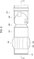
- Fig. 1 is a schematic view of an example of the structure of an ultrasonic inspection system that uses the ultrasonic endoscope according to the present invention.
- An ultrasonic inspection system 10 shown in Fig. 1 is a system that enables observation of the gallbladder or the pancreas, which is difficult to observe by using ultrasonic inspection from the body surface of a subject such as a patient, via digestive tract such as the esophagus, the stomach, the duodenum, the small intestine, the large intestine, and the like, each of which is a body cavity of the subject.
- the ultrasonic inspection system 10 inserts an ultrasonic endoscope according to the present invention, which has an ultrasonic observation portion that captures an ultrasound tomographic image (hereinafter, referred to an ultrasound image) and an endoscopic observation portion that captures an endoscopic optical image (hereinafter, referred to as an endoscopic image), into a body cavity of a subject and captures the ultrasound image of an observation target site of the subject while observing the endoscopic image of the subject.
- an ultrasound image an ultrasound tomographic image
- an endoscopic observation portion that captures an endoscopic optical image
- the ultrasonic inspection system 10 includes an ultrasonic endoscope 12 having a heat dissipation structure that is a feature of the present invention, an ultrasonic processor device 14 that generates an ultrasound image, an endoscope processor device 16 that generates an endoscopic image, a light source device 18 that supplies illumination light for illuminating the inside of a body cavity to the ultrasonic endoscope 12, and a monitor 20 that displays the ultrasound image and/or the endoscopic image.
- the ultrasonic inspection system 10 further includes a water supply tank 21a that stores cleaning water or the like and a suction pump 21b that suctions a suction object (including the supplied cleaning water and the like) in a body cavity.
- the ultrasonic inspection system 10 may include a supply pump or the like that supplies cleaning water in the water supply tank 21a or a gas, such as outside air, to a pipe line (not shown) in the ultrasonic endoscope 12.
- the ultrasonic endoscope 12 shown in Fig. 1 has, at the distal end thereof, an ultrasonic observation portion 36, having a heat dissipation structure that is a feature of the present invention, and an endoscopic observation portion 38.
- the ultrasonic endoscope 12 captures an ultrasound image (echo signal) and an endoscopic image (image signal) of the inside of the body cavity.
- the ultrasonic endoscope 12 is composed of an insertion portion 22 that includes the ultrasonic observation portion 36 and the endoscopic observation portion 38 at an end thereof and that is inserted into a body cavity of a subject; an operating unit 24 that is connected to a proximal end portion of the insertion portion 22 and with which an operator, such as a doctor or an engineer, performs an operation; and a universal cord 26 one end of which is connected to the operating unit 24.
- the operating unit 24 has an air/water supply button 28a, for opening or closing an air/water supply pipe line (not shown) from the water supply tank 21a, and a suction button 28b, for opening or closing a suction pipe line (not shown) from the suction pump 21b, which are arranged side by side. Moreover, the operating unit 24 has a pair of angle knobs 29 and a treatment tool insertion port 30 (forceps port).
- the water supply tank 21a stores cleaning water or the like that is supplied to the air/water supply pipe line in the ultrasonic endoscope 12 for cleaning the endoscopic observation portion 38 of the ultrasonic endoscope 12 and the like.
- the air/water supply button 28a is used to eject a gas such as air and water such as cleaning water, which are supplied from the water supply tank 21a through the air/water supply pipe line, from the endoscopic observation portion 38 on the distal end side of the insertion portion 22.
- the suction pump 21b suctions a suction pipe line (not shown) to suction a suction object (including supplied cleaning water and the like) in a body cavity from the distal end side of the ultrasonic endoscope 12.
- the suction button 28b is used to suction a suction object in a body cavity from the distal end side of the insertion portion 22 by using a suction force of the suction pump 21b.
- the treatment tool insertion port 30 is used to insert a treatment tool, such as forceps, a puncture needle, a high-frequency knife, or the like.
- an ultrasound connector 32a connected to the ultrasonic processor device 14, an endoscope connector 32b connected to the endoscope processor device 16, and a light source connector 32c connected to the light source device 18 are provided.
- the ultrasonic endoscope 12 is removably connected to the ultrasonic processor device 14, the endoscope processor device 16, and the light source device 18 via the connectors 32a, 32b, and 32c, respectively.
- An air/water supply tube 34a, for connecting to the water supply tank 21a, a suction tube 34b, for connecting the suction pump 21b, and the like are connected to the light source connector 32c.
- the insertion portion 22 is composed of, in order from the distal end side, a distal end portion 40 (distal end rigid portion) that is formed of a rigid member and that has the ultrasonic observation portion 36 and the endoscopic observation portion 38; a bending portion 42 that is connected to the proximal end side of the distal end portion 40, that is formed by coupling a plurality of bending pieces, and that can be bent freely; and a soft portion 43 that couples the proximal end side of the bending portion 42 and the distal end side of the operating unit 24 to each other, that has a thin and elongated shape, and that has flexibility.
- the bending portion 42 is remote-controlled so as to be bent by rotating the pair of angle knobs 29 of the operating unit 24. Therefore, the distal end portion 40 can be directed in a desired direction.
- a balloon which covers the ultrasonic observation portion 36 and into which an ultrasound transmission medium (such as water, oil, or the like) is injected, may be removably attached to the distal end portion 40. Because ultrasound and an echo signal are considerably attenuated in air, by inflating the balloon by injecting the ultrasound transmission medium into the balloon and causing the balloon to contact an observation target site, it is possible to remove air from a space between an ultrasonic transducer array 50 (see Figs. 2 to 4 ) of the ultrasonic observation portion 36 and the observation target site and to prevent attenuation of the ultrasound and the echo signal.
- an ultrasound transmission medium such as water, oil, or the like
- the ultrasonic processor device 14 generates and supplies an ultrasound signal (data), for generating ultrasound, to the ultrasonic transducer array 50 (see Figs. 2 to 4 ) of an ultrasonic transducer unit 46 of the ultrasonic observation portion 36 of the distal end portion 40 of the insertion portion 22 of the ultrasonic endoscope 12. Moreover, the ultrasonic processor device 14 receives and obtains an echo signal (data), which is reflected from an observation target site to which ultrasound is emitted, with the ultrasonic transducer array 50; and generates an ultrasound image, which is to be displayed on the monitor 20, by performing various types of signal (data) processing on the obtained echo signal.
- data for generating ultrasound
- the endoscope processor device 16 receives and obtains a captured image signal (data) that is obtained from an observation target site, which is illuminated with illumination light from the light source device 18, in the endoscopic observation portion 38 of the distal end portion 40 of the insertion portion 22 of the ultrasonic endoscope 12.
- the endoscope processor device 16 generates an endoscopic image, which is to be displayed on the monitor 20, by performing various types of signal (data) processing on the obtained image signal.
- the processor devices 14 and 16 may be composed of a processor such as a personal computer (PC) or the like.
- the light source device 18 In order to obtain an image signal by capturing an image of an observation target site in a body cavity by using the endoscopic observation portion 38 of the ultrasonic endoscope 12, the light source device 18 generates illumination light, such as white light or a specific wavelength light, composed of three primitive color light that is, for example, red light (R), green light (G), and blue light (B), and supplies the illumination light to the ultrasonic endoscope 12.
- the illumination light propagates via a light guide (not shown) or the like in the ultrasonic endoscope 12, is emitted from the endoscopic observation portion 38 of the distal end portion 40 of the insertion portion 22 of the ultrasonic endoscope 12, and illuminates the observation target site in the body cavity.
- the monitor 20 receives image signals generated by the ultrasonic processor device 14 and the endoscope processor device 16 and displays an ultrasound image and an endoscopic image.
- An image to be displayed on the monitor 20 can be switched between the ultrasound image and the endoscopic image, and both of these images can be simultaneously displayed on the monitor 20.
- a monitor for displaying the ultrasound image and a monitor for displaying an endoscopic image may be independently provided, or the ultrasound image and the endoscopic image may be displayed in any other appropriate form.
- Fig. 2 is a partial enlarged plan view of the distal end portion of the insertion portion of the ultrasonic endoscope shown in Fig. 1 and the vicinity of the distal end portion.
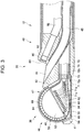
- Fig. 3 is a partial longitudinal sectional view taken along line III-III in Fig. 2 , illustrating the distal end portion of the insertion portion of the ultrasonic endoscope shown in Fig. 2 that is cut along the centerline in the longitudinal direction thereof.
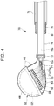
- Fig. 4 is a schematic partial longitudinal sectional view of a heat dissipation structure of the distal end portion of the insertion portion of the ultrasonic endoscope shown in Figs. 1 to 3 .
- the distal end portion 40 of the ultrasonic endoscope 12 has the ultrasonic observation portion 36, for obtaining an ultrasound image, on the distal end side; the endoscopic observation portion 38, for obtaining an endoscopic image, on the proximal end side; and a treatment tool lead-out port 44 between these.
- the observation portions 36 and 38 are attached to and held by an exterior member 41 that is the body of the distal end portion 40 of the ultrasonic endoscope 12 and that is made of a rigid material such as a rigid resin.
- the treatment tool lead-out port 44 is formed between the ultrasonic observation portion 36 and the endoscopic observation portion 38.
- the treatment tool lead-out port 44 may be formed in the endoscopic observation portion 38 or may be formed on the proximal end side (the bending portion 42 side) relative to the endoscopic observation portion 38.
- the ultrasonic observation portion 36 is composed of the ultrasonic transducer unit 46, the exterior member 41 for attaching and holing the ultrasonic transducer unit 46, and a cable portion 70 that includes a plurality of coaxial cables 71 that are connected to the ultrasonic transducer unit 46.
- the ultrasonic transducer unit 46 has the ultrasonic transducer array 50 that is composed of a plurality of ultrasonic transducers 48, a backing material layer 52 that supports the ultrasonic transducers 48 of the ultrasonic transducer array 50 from the lower surface side, a wiring board 54 that is embedded in the backing material layer 52 and that is electrically connected to the plurality of ultrasonic transducers 48, a copper foil 62 (first heat conductive member) that is disposed along a side surface of the backing material layer 52 in the width direction and end surfaces of the plurality of ultrasonic transducers 48 in the longitudinal direction, and a filler layer 68 that fills a space between the exterior member 41 and the backing material layer 52.
- a wiring portion 56 that has a plurality of connection portions 58, to which signal wires 71a at one ends of the plurality of coaxial cables 71 are connected, is provided.
- drive voltage signals to the plurality of ultrasonic transducers 48 and ultrasonic echo signals (voltage signals) from the plurality of ultrasonic transducers 48 are applied to the individual electrodes of the plurality of ultrasonic transducers 48.
- the plurality of coaxial cables 71 are electrically connected to the ultrasonic processor device 14 at the other ends thereof.
- the signal wires 71a of the plurality of coaxial cables 71 are each electrically connected to a corresponding one of the plurality of ultrasonic transducers 48.
- the wiring board 54 has, in the wiring portion 56, a ground portion 60 that is electrically connected, via a lead wire or the like, to a transducer ground (not shown) that is a ground electrode of the ultrasonic transducer array 50.
- the ground portion 60 may be connected to shield layers 71c of the plurality of coaxial cables 71.
- the ultrasonic transducer unit 46 further has an acoustic matching layer 64 that is laminated on the ultrasonic transducer array 50, and an acoustic lens 66 that is laminated on the acoustic matching layer 64. That is, the ultrasonic transducer unit 46 is composed of a laminated body 47 in which the acoustic lens 66, the acoustic matching layer 64, the ultrasonic transducer array 50, and the backing material layer 52 are laminated.
- the acoustic matching layer 64 performs acoustic impedance matching between a subject, such as a human body, and the ultrasonic transducers 48.
- the acoustic lens 66 which is attached onto the acoustic matching layer 64, causes ultrasound, which is emitted from the ultrasonic transducer array 50, to converge toward an observation target site.
- the acoustic lens 66 is made of, for example, a silicone-based resin (a millable silicone rubber (HTV rubber), a liquid silicone rubber (RTV rubber), or the like), a butadiene-based resin, a polyurethane-based resin, or the like.
- powder of titanium oxide, alumina, silica, or the like is mixed into the acoustic lens 66 as necessary.
- the cable portion 70 of the ultrasonic observation portion 36 has a heat dissipation structure that is the feature of the present invention. As illustrated in Fig. 4 , the cable portion 70 has the plurality of coaxial cables 71 disposed on the central side, an insulating jacket 72a that covers the plurality of coaxial cables 71, an electroconductive shield member 73 that is disposed so as to cover the jacket 72a and that can be grounded to the housing of the ultrasonic endoscope 12, and a jacket 72b that covers the outside of the shield member 73.
- the cable portion 70 has a first insulation tube 74 for covering and protecting the outer periphery of the outer jacket 72b; an electroconductive connection pipe 76 that is disposed on the proximal end side of the cable portion 70 (a side opposite to the laminated body 47) and that covers at least a part of the first insulation tube 74; and a second insulation tube 78 that is connected to an end portion of the connection pipe 76 on a side opposite to the ultrasonic transducer unit 46 and that covers a connection portion with the connection pipe 76 and the first insulation tube 74 on the universal cord 26 side relative to the connection pipe 76.
- a second heat conductive member 80 is disposed so as to fill at least a part of a space between the first insulation tube 74 and the connection pipe 76.
- the shield member 73 of the cable portion 70 may be made from a metal member or the like, provided that the shield member 73 covers the plurality of coaxial cables 71 from the outside and has electroconductivity.
- Fig. 4 which is a figure simplified for convenience of description, only the ultrasonic transducer array 50, the backing material layer 52, the copper foil 62, the wiring board 54, and the cable portion 70 are illustrated, and other members are omitted.
- grounding in the present invention is not limited to causing the potential of an electroconductive member to be zero, and also includes a case where, for example, the voltage of an electroconductive member is maintained at a predetermined low voltage by connecting the electroconductive member to a member having a large electric capacity.
- the plurality of coaxial cables 71 are electrically connected to the plurality of connection portions 58 of the wiring portion 56 of the wiring board 54.
- the shield member 73 is thermally connected to the copper foil 62 of the ultrasonic transducer unit 46 at an end portion thereof on the ultrasonic transducer unit 46 side. Therefore, in order from the end portion of the cable portion 70 on the ultrasonic transducer unit 46 side, the coaxial cables 71 and the inner jacket 72a are exposed in the ultrasonic observation portion 36. At a portion of the exposed inner jacket 72a that is adjacent to a side opposite to the ultrasonic transducer unit 46, the outer jacket 72b is removed and the shield member 73 is exposed, and the exposed shield member 73 and the copper foil 62 are connected to each other.
- the ultrasonic transducer array 50 of the ultrasonic transducer unit 46 shown in Figs. 2 and 3 is, for example, an array of 48 to 192 channels (CH) that is composed of 48 to 192 pieces of rectangular-parallelepiped-shaped ultrasonic transducers 48 that are arranged in an outwardly convex arc shape.
- CH channels
- the ultrasonic transducer array 50 is formed by arranging the plurality of ultrasonic transducers 48, for example, in a one-dimensional array shape at a predetermined pitch as in the example shown in the figures.
- the ultrasonic transducers 48 of the ultrasonic transducer array 50 are arranged at a regular pitch in the axial direction of the distal end portion 40 (the longitudinal axial direction of the insertion portion 22) in a convexly curved shape and are sequentially driven on the basis of drive signals that are input from the ultrasonic processor device 14.
- convex electronic scan is performed over a scan range that is a range in which the ultrasonic transducers 48 are arranged as shown in Fig. 2 .
- the length of the ultrasonic transducer array 50 in the width direction of the ultrasonic transducer array 50 is smaller than the length of the ultrasonic transducer array 50 in a direction parallel to the bottom surface of the backing material layer 52 (the azimuth (AZ) direction).
- the ultrasonic transducer array 50 is disposed so as to be inclined in such a way that the back end side thereof protrudes.
- the ultrasonic transducer 48 has a structure in which, for example, electrodes are formed on both surfaces of a thick piezoelectric film of lead zirconate titanate (PZT), polyvinylidene fluoride (PVDF), or the like.
- An electrode of the ultrasonic transducer array 50 is an individual electrode (not shown) that is independently provided in each ultrasonic transducer 48, and the other electrode is a transducer ground (transducer ground electrode) (not shown), which is common to all of the ultrasonic transducers 48.
- a plurality of the individual electrodes are disposed on the lower surfaces of end portions of the plurality of ultrasonic transducers 48, and the transducer ground may be disposed on the upper surfaces of the end portions of the ultrasonic transducers 48.
- the plurality of individual electrodes and the transducer ground constitute an electrode portion of the ultrasonic transducer array 50.
- Each gap between two adjacent ultrasonic transducers 48 is filled with a filler, such as an epoxy resin or the like.
- the ultrasonic transducer unit 46 of the ultrasonic observation portion 36 when each of the ultrasonic transducers 48 of the ultrasonic transducer array 50 is driven and a voltage is applied to both electrodes of the ultrasonic transducer 48, the piezoelectric body vibrate and successively generates ultrasound, and the ultrasound is emitted toward an observation target site of a subject.
- an electronic switch such as a multiplexer
- ultrasound is scanned over a scan range along a curved surface on which the ultrasonic transducer array 50 is disposed, such as a range of about several tens of millimeters from the center of curvature of the curved surface.
- the piezoelectric body When receiving an echo signal (ultrasonic echo) reflected from the observation target site, the piezoelectric body vibrates and generates a voltage, and this voltage is output to the ultrasonic processor device 14 as an electric signal corresponding to the received ultrasonic echo (ultrasound detection signal).
- the ultrasonic processor device 14 performs various types of signal processing on the electric signal, and then an ultrasound image is displayed on the monitor 20.
- Heat is generated in each of piezoelectric bodies of the plurality of ultrasonic transducers 48 when, As described above, a drive voltage is applied to the plurality of ultrasonic transducers 48 and the piezoelectric bodies of the plurality of ultrasonic transducers 48 vibrate and generate ultrasound emitted toward a target object, and when the plurality of ultrasonic transducers 48 receive an ultrasonic echo of ultrasound, which has been emitted from the plurality of ultrasonic transducers 48 and reflected by the target, and the piezoelectric bodies vibrates and generate an ultrasonic echo signal (voltage signal).
- One of means for increasing the resolution of an ultrasound image, that is, for improving accuracy in ultrasonic diagnosis is means of increasing the power of drive signals (voltage signals) of the plurality of ultrasonic transducers 48.
- drive signals voltage signals
- heat generated in the piezoelectric body increases. Therefore, by providing a heat dissipation structure that is a feature of the present invention in the distal end portion 40 of the ultrasonic endoscope 12, it is possible to efficiently dissipate heat generated in the piezoelectric body and to improve accuracy in ultrasonic diagnosis.
- the ultrasonic transducer array 50 has a plurality of (48 to 192) electrodes (not shown) that are electrically continuous with the plurality of (48 to 192) ultrasonic transducers 48.
- the plurality of electrodes that are electrically continuous with the plurality of ultrasonic transducers 48 may be disposed on a side surface of the ultrasonic transducer array 50 in the width direction, or may be on the central side of the ultrasonic transducer array 50 as in the present embodiment.
- the plurality of electrodes that are electrically continuous with the ultrasonic transducers 48 are disposed on the side surface side of the ultrasonic transducer array 50 in the width direction, if the number of the ultrasonic transducers 48 is small, the plurality of electrodes may be disposed on one surface side. However, in order to improve the accuracy in ultrasonic diagnosis, preferably, the number of the ultrasonic transducers 48 is large. Therefore, preferably, the plurality of electrodes that are electrically continuous with the ultrasonic transducers 48 are disposed on both surface sides of the ultrasonic transducer array 50 in the width direction.
- the plurality of electrodes that are electrically continuous with the plurality of ultrasonic transducers 48 are disposed on the central side of the ultrasonic transducer array 50 in the width direction, because the wiring portion can be disposed in the backing material layer 52, the space in the distal end portion 40 of the insertion portion 22 is not squeezed. Therefore, even in a case where, for example, the ultrasonic transducers 48 are arranged in multiple rows, the space in the distal end portion 40 can be effectively used.
- the transducer ground (not shown) of the plurality of ultrasonic transducers 48 is an electrode that is different from the plurality of electrodes (not shown) that are disposed on the central side of the ultrasonic transducer array 50 in the width direction.
- the transducer ground is electrically connected to the ground portion 60 of the wiring portion 56 of the wiring board 54, which is a grounded member, by using a lead wire or the like.
- the ground potential in the ultrasonic endoscope 12 is preferably the same reference potential, preferably, the transducer ground of the plurality of ultrasonic transducers 48 is a common electrode to which the ultrasonic transducers 48 are grounded.
- the backing material layer 52 of the ultrasonic transducer unit 46 is a layer that is made of a backing material and that is disposed inside with respect to the arrangement surface of the plurality of ultrasonic transducers 48, that is, on the back surface (lower surface) of the ultrasonic transducer array 50. Accordingly, the backing material layer 52 has a function of mechanically and softly supporting the ultrasonic transducer array 50 and a function of attenuating, among ultrasound signals emitted from the plurality of ultrasonic transducers 48 or reflected and propagated from an observation target, ultrasound that has propagated to the backing material layer 52 side. Therefore, the backing material is a material having rigidity, such as a rigid rubber, to which an ultrasound attenuation material (such as ferrite or a ceramic) is added as necessary.
- an ultrasound attenuation material such as ferrite or a ceramic
- the ultrasonic transducer array 50 is an array in which the plurality of ultrasonic transducers 48 each having a rectangular-parallelepiped shape in the example shown in the figures are arranged at a regular pitch on the arc-shaped upper surface of the backing material layer 52, which is an upper surface having a convex arc-shaped cross section, in such a way that the longitudinal directions of the plurality of ultrasonic transducers 48 are parallel to each other, that is, an array in which the plurality of ultrasonic transducers 48 are arranged in an arc shape so as to face outward.
- the shape of the backing material layer 52 may be any appropriate shape that does not impair the functions described above.
- the backing material layer 52 may have a substantially semi-cylindrical shape shown in Fig. 3 , and may have a recessed portion.
- the filler layer 68 of the ultrasonic transducer unit 46 fills a space between the exterior member 41 and the backing material layer 52.
- the filler layer 68 also has a function of fixing the wiring board 54, the plurality of coaxial cables 71, the copper foil 62, and various wiring portions.
- the acoustic impedance of the filler layer 68 matches the acoustic impedance of the backing material layer 52 with an accuracy of a predetermined degree or higher so that a boundary surface between the filler layer 68 and the backing material layer 52 may not reflect an ultrasound signal propagated from the ultrasonic transducer array 50 toward the backing material layer 52 side.
- the filler layer 68 has heat dissipation ability in order to increase the efficiency in dissipating heat generated in the plurality of ultrasonic transducers 48.
- heat dissipation efficiency can be improved.
- a part of the wiring board 54 of the ultrasonic transducer unit 46 is embedded in the backing material layer 52.
- the wiring board 54 has, in a portion thereof embedded in the backing material layer 52, a plurality of electrodes (not shown) that are electrically continuous with the plurality of ultrasonic transducers 48, a plurality of electrode pads (not shown) that are electrically connected by using lead wires or the like, the wiring portion 56 that is composed of the plurality of connection portions 58 that are terminals connected to the signal wires 71a of the plurality of coaxial cables 71 of the cable portion 70, and the ground portion 60 that is electrically connected to the transducer ground (not shown) of the plurality of ultrasonic transducers 48.
- the wiring board 54 may be a board made of a rigid material, or may be a flexible printed circuit (hereinafter, simply referred to as "FPC"). As in the present embodiment, in a case where a part of the wiring board 54 is embedded in the backing material layer 52, preferably, the wiring board 54 is made of a rigid material in order to fix the position of the wiring portion 56 and to prevent wire breakage at the wiring portion.
- FPC flexible printed circuit
- an FPC is used as the wiring board 54 in order to, for example, improve the operational efficiency of wiring.
- the copper foil 62 of the ultrasonic transducer unit 46 is affixed along the side surfaces of the ultrasonic transducer array 50 and the backing material layer 52 in the width direction.
- the copper foil 62 conducts heat generated in the plurality of ultrasonic transducers 48.
- at least a part of the copper foil 62 is extended to the shield member 73 of the cable portion 70 and is thermally connected to the shield member 73.
- the shield member 73 is an electroconductive member, in a case where the shield member 73 is grounded to the housing of the ultrasonic endoscope 12 or the like at a proximal end portion thereof opposite to the distal end portion 40 of the insertion portion 22, the potential of the copper foil 62 can be made to be the ground potential. Therefore, the copper foil 62 can be prevented from electromagnetically interfering with ultrasonic echo signals (voltage signals) obtained from the plurality of ultrasonic transducers 48.
- the copper foil 62 may be connected to the ground portion 60 of the wiring board 54.
- the copper foil 62 used in the present embodiment is an electroconductive member for the above reasons.
- the copper foil 62 may be any member having high heat conductivity. Therefore, instead of the copper foil 62, an aluminum foil, an electroconductive silicone sheet, or the like may be used.
- the shape of the copper foil 62 is not limited to a foil shape.
- the copper foil 62 has a mesh shape or a sheet shape that is thicker than a foil so that the copper foil 62 can sufficiently conduct heat from the side surfaces of the ultrasonic transducer array 50 and the backing material layer 52 in the width direction.
- a portion of the copper foil 62 that is affixed along the outer surfaces of the ultrasonic transducer array 50 and the backing material layer 52 and a portion of the copper foil 62 that is extended to the shield member 73 of the cable portion 70 need not be integrated.
- the shape of the portion that is extended to the shield member 73 is not limited to a shape that is the same as the shape of the portion affixed to the side surface of the backing material layer 52, such as a mesh shape or a sheet shape, and may be another shape, such as a lead-wire shape, a bar-like shape, or the like.
- the material of the portion disposed along the backing material layer 52 and the material of the portion that is extended to the shield member 73 may be different from each other.
- the wiring portion 56 of the wiring board 54 is composed of the connection portions 58, which are a plurality of terminals that are disposed on at least one surface of the wiring board 54, that are electrically connected to the signal wires 71a of the plurality of coaxial cables 71 of the cable portion 70, and that are electrically connected to a plurality of electrode pads (not shown) that are electrically continuous with the plurality of ultrasonic transducers 48.
- the wiring portion 56 is disposed on the backing material layer 52 side relative to the ground portion 60 of the wiring board 54.
- the position of the wiring portion 56 is not particularly limited.
- the wiring portion 56 may be disposed at any appropriate position in order to, for example, improve the operation efficiency in wiring.
- the number of the plurality of connection portions 58 of the wiring portion 56 is at least equal to the number of channels of the ultrasonic transducer array 50. Therefore, as necessary, the plurality of connection portions 58 may be disposed on the wiring board 54 in multiple rows.
- the ground portion 60 of the wiring board 54 is an electroconductive member that is connected to the transducer ground of the plurality of ultrasonic transducers 48 (not shown) and to the shield layers 71c of the plurality of coaxial cables 71.
- the ground portion 60 makes the ground potentials of the shield layers 71c of the plurality of coaxial cables 71 be the same potential. Therefore, for example, in order to increase the number of heat dissipation paths from the plurality of ultrasonic transducers 48, the ground portion 60 may be further electrically connected to the shield member 73 of the cable portion 70.
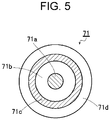
- each of the plurality of coaxial cables 71 of the cable portion 70 has a signal wire 71a that is on the central side thereof and that is electrically connected to a corresponding one of the plurality of connection portions 58 of the wiring portion 56 of the wiring board 54; an insulating jacket 71b that is disposed in a layer outside of the signal wire 71a; a shield layer 71c that is disposed in a layer outside of the jacket 71b, that can be grounded on the proximal end side (the universal cord 26 side) of the ultrasonic endoscope 12, and that is made of an electroconductive material such as a metal; and an insulating jacket 71d that is disposed in the outermost layer.
- the plurality of coaxial cables 71 are used on the central side of the cable portion 70.
- cables (shield cables) that have structures different from the coaxial cables 71 described above may be used, provided that the cables each have a signal wire, for transmitting/receiving a voltage signal by being electrically connected to a corresponding one of the plurality of ultrasonic transducers 48, and a shield portion that is made of a metal and that can be grounded by being electrically connected to a transducer ground (not shown) of a corresponding one of the plurality of ultrasonic transducers 48.
- the shield cable it is possible to use a cable having a known structure, such as a cable unit that includes, on the central side thereof, a plurality of signal wires covered by an insulating jacket and a plurality of lead wires that can be grounded; and has a jacket that covers the plurality of signal wires and the lead wires.
- the arrangement of the signal wires and the lead wires of the cable unit is not limited to the one described above.
- the plurality of signal wires and lead wires may be randomly arranged in the outer jacket that covers these wires.
- the first insulation tube 74 of the cable portion 70 is an insulating tube for covering and protecting the plurality of coaxial cables 71, the inner jacket 72a, and the shield member 73. Therefore, the first insulation tube 74 is disposed so as to cover the shield member 73, which is exposed by removing the outer jacket 72b in order to connect the copper foil 62.
- the first insulation tube 74 is not particularly limited, provided that the first insulation tube 74 has a certain degree of flexibility and insulation ability for following a bending operation of bending the bending portion 42 of the insertion portion 22 and for protecting the plurality of coaxial cables 71, the shield member 73, and the connection portion between the shield member 73 and the copper foil 62.
- a known insulation tube, such as a heat shrinkable tube, may be used.
- connection pipe 76 of the cable portion 70 is a member for dissipating heat that is conducted from the shield member 73 by contacting the second heat conductive member 80.
- the connection pipe 76 covers a portion of the first insulation tube 74 having a predetermined length and is disposed on the operating unit 24 side (proximal end side) relative to the distal end portion 40 so as not to dissipate heat into the distal end portion 40 of the insertion portion 22.
- the length of the connection pipe 76 may be a length that does not impede a bending operation of the bending portion 42, and preferably is as large as possible in order to maintain heat dissipation ability.
- the connection pipe 76 is made of a material having high heat conductivity, such as a stainless steel or another metal.
- the second insulation tube 78 of the cable portion 70 which covers the first insulation tube 74, protects the cable portion 70 from the outside and fixes the connection pipe 76 at a position outside the first insulation tube 74.
- An end portion of the second insulation tube 78 on the ultrasonic transducer unit 46 side is connected to an end of the connection pipe 76 on a side opposite to the ultrasonic transducer unit 46 (proximal end side).
- the second insulation tube 78 is disposed on the proximal end side of the ultrasonic endoscope 12 so as to cover a part of the connection pipe 76 on the proximal end side and a part of the first insulation tube 74, that is, a part on the proximal end side relative to the connection pipe 76.
- the second insulation tube 78 is not particularly limited, provided that the second insulation tube 78 has a certain degree of flexibility and insulation ability.
- a known insulation tube, such as a heat shrinkable tube, may be used.
- the second heat conductive member of the cable portion 70 is disposed in contact with the first insulation tube 74 and the connection pipe 76 and conducts heat, which has been conducted to the shield member 73, to the connection pipe 76.
- the second heat conductive member 80 is a cylindrical member that is disposed between the first insulation tube 74 and the connection pipe 76 on the distal end side of the connection pipe 76.
- the second heat conductive member 80 may conduct heat from the shield member 73 via the outer jacket 72b and the first insulation tube 74 of the cable portion 70. Therefore, preferably, the second heat conductive member 80 has high heat conductivity.
- the second heat conductive member 80 is made of a metal such as copper or aluminum, a ceramic having high heat conductivity, heat conductive silicone, or the like.
- the second heat conductive member 80 is disposed so as to fill at least a part of a space between the first insulation tube 74 and the connection pipe 76. Therefore, the second heat conductive member 80 need not have a cylindrical shape as in the example shown in Fig. 4 .
- the second heat conductive member 80 is disposed in contact with the first insulation tube 74 and the connection pipe 76 over as large area as possible.
- the second heat conductive member 80 may be disposed so as to fill the entirety of a space between the first insulation tube 74 and the connection pipe 76. Moreover, preferably, the second heat conductive member 80 is disposed in such a way that the second heat conductive member 80 can be easily removed for repair or the like. For example, the second heat conductive member 80 may be disposed so as to protrude slightly from the distal end of the connection pipe 76.
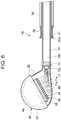
- a second heat conductive member 81 includes a cylindrical portion that is disposed between the first insulation tube 74 and the connection pipe 76 and an outward flange 81a that has a cylindrical shape having an outside diameter that is larger than or equal to the inside diameter of the connection pipe 76. As illustrated in Fig. 6 , preferably, the second heat conductive member 81 is disposed in such a way that the outward flange 81a contacts an end surface of the connection pipe 76 on the distal end side.
- the second heat conductive member 81 is in contact with, in addition to a space between the first insulation tube 74 and the connection pipe 76, the end surface of the connection pipe 76 on the distal end side, the heat dissipation path to the connection pipe 76 can be widened. Because the outward flange 81a contacts the end surface of the connection pipe 76 on the distal end side, it is possible to prevent the connection pipe 76 from moving toward the distal end side relative to the first insulation tube 74 and the second heat conductive member 81, which may occur due to, for example, vibration during use of the ultrasonic endoscope 12.
- the outward flange 81a which has an outside diameter that is larger than the inside diameter of the connection pipe 76, is located on the distal end side relative to the connection pipe 76, when performing reassembling after removing the second heat conductive member 81 for repair or the like, the insertion position of the second heat conductive member 81 can be easily determined.
- Fig. 6 which is a figure that is simplified for convenience of description as with Fig. 4 , only the ultrasonic transducer array 50, the backing material layer 52, the copper foil 62, the wiring board 54, and a cable portion 79 are illustrated, and the other members is omitted.
- the second heat conductive member 81 is not limited to a member that has a cylindrical shape, provided that the second heat conductive member 81 can contact at least a space between the first insulation tube 74 and the connection pipe 76 and an end portion of the connection pipe 76 on the distal end side. That is, it is sufficient that the second heat conductive member 81 shown in Fig.
- the second heat conductive member 81 may be disposed so as to fill at least a part of a space between the first insulation tube 74 and the connection pipe 76. Accordingly, in this case, as in the example shown in Fig.
- the heat dissipation path to the connection pipe 76 can be widened, and it is possible to prevent a portion of the cable portion 79 inside of the connection pipe 76 from moving toward the proximal end side and the distal end side relative to the connection pipe 76.
- the second heat conductive members 80 and 81 conduct heat from the shield members 73 via the outer jackets 72b and the first insulation tubes 74 of the cable portions 70 and 79.
- the outer jackets 72b and the first insulation tubes 74 of the cable portions 70 and 79 which have low heat conductivity, impede efficient dissipation of heat that is conducted to the shield members 73. Therefore, in order to improve efficiency in dissipating heat that is conducted to the shield members 73, preferably, the shield members 73 are in direct contact with the second heat conductive members 80 and 81.
- a part of the outer jacket 72b of a cable portion 82 on the distal end side of the connection pipe 76 is removed, and the shield member 73 is exposed.
- a part of the first insulation tube 74 is removed, and the shield member 73 is exposed to the outside.
- a second heat conductive member 83 having a cylindrical shape is disposed in such a way that the second heat conductive member 83 contacts the portion where the shield member 73 is exposed to the outside, covers the portion where the first insulation tube 74 is removed, and contacts the distal end side of the connection pipe 76.
- the shield member 73 that is electrically continuous with the transducer ground (not shown) of electrode portion (not shown), which is the ground electrode of the ultrasonic transducer unit 46, is exposed to the outside.
- an insulating layer 84 that covers the exposed shield member 73, the second heat conductive member 83, the connection pipe 76, and the second insulation tube 78 is disposed outside of the connection pipe 76.
- Fig. 7 which is a figure that is simplified for convenience of description as with Figs. 4 and 6 , only the ultrasonic transducer array 50, the backing material layer 52, the copper foil 62, the wiring board 54, and the cable portion 82 are illustrated, and the other members are omitted.
- the shape of the second heat conductive member 83 is not particularly limited, provided that the second heat conductive member 83 can contact the shield member 73 and the connection pipe 76 of the cable portion 82.
- a heat conductive member having any appropriate shape described above may be used.
- a heat conductive member having a C-shape which is the shape of a cylinder from which a part of an arc is cut away, may be used.
- the insulating layer 84 which is disposed outside of the connection pipe 76, it is sufficient that the insulating layer 84 is disposed so as to cover at least the exposed portion the shield member 73.
- a known insulation tube such as a heat shrinkable tube or the like, can be used as the insulating layer 84.
- Increasing the heat dissipation paths is one of means for efficiently dissipating heat that is generated in the plurality of ultrasonic transducers 48 and conducted to the shield members 73 of the cable portions 70, 79, and 82 shown in Figs. 3 , 4 , 6 , and 7 .
- a third heat conductive member 86 which fills a space between the first insulation tube 74, and a portion of the connection pipe 76 on the proximal end side and the second insulation tube 78, is provided.
- the third heat conductive member 86 extends from the proximal end side of the connection pipe 76 to the proximal end side of a cable portion 85.
- the third heat conductive member 86 conducts both of heat that is conducted from the shield member 73 of the cable portion 85 through the second heat conductive member 80 and the connection pipe 76, and heat that is conducted from the shield member 73 through the outer jacket 72b of the cable portion 85 and the first insulation tube 74; and dissipates the both to the proximal end side.
- the ultrasonic endoscope 12 has, in addition to the heat dissipation path that dissipates heat to the proximal end side of the shield member 73 and the heat dissipation path that dissipates heat from the connection pipe 76 to the outside, a heat dissipation path to the proximal end side of the third heat conductive member 86. Therefore, the ultrasonic endoscope 12 can further improve heat dissipation efficiency.
- Fig. 8 which is a figure that is simplified for convenience of description as with Figs. 4 , 6 , and 7 , only the ultrasonic transducer array 50, the backing material layer 52, the wiring board 54, the copper foil 62, and the cable portion 85 are illustrated, and the other elements are omitted.
- the third heat conductive member 86 of the cable portion 85 extends to the proximal end side of the cable portion 85 relative to the connection pipe 76 between the first insulation tube 74 and the second insulation tube 78. Therefore, for ease of disposition and the like, the third heat conductive member 86 is formed as a heat conductive layer on the surface of the first insulation tube 74.
- the heat conductive layer can be formed on the surface of the first insulation tube 74.
- the third heat conductive member 86 which is disposed as a heat conductive layer, is made of a material that has high heat conductivity and that has flexibility that allows the third heat conductive member 86 to follow a bending operation of bending the bending portion 42.
- epoxy adhesive 122-07 made by Creative Materials Inc.
- heat conductive grease X-23-8033-1 made by Shin-Etsu Silicones Co., Ltd., or, in a case of using electroless plating, copper or the like may be used.
- a heat conductive layer formed on the first insulation tube 74 is preferably used as the third heat conductive member 86.
- a heat conductive member may be formed on an inner wall of the connection pipe 76 and an inner wall of the second insulation tube 78, provided that the heat conductive member contacts the first insulation tube 74 and the connection pipe 76 and extends to the proximal end of the cable portion 85.
- the third heat conductive member 86 need not disposed as a layer and may have a mesh shape, a sheet shape, or the like.
- the third heat conductive member 86 need not be disposed over the entire area where the second insulation tube 78 covers the first insulation tube 74.
- the third heat conductive member 86 may be partially disposed or may contact the second heat conductive member 80.
- heat generated from the plurality of ultrasonic transducers 48 of the ultrasonic transducer array 50 can be conducted to the copper foil 62, which is a heat conductive member; and the heat can be dissipated from the copper foil 62 to the shield members 73 of the cable portions 70, 79, 82, and 85.
- the shield member 73 is grounded, because the copper foil 62 also has a ground potential, the copper foil 62 and the plurality of ultrasonic transducers 48 do not electromagnetically interfere with each other, and noise received from the outside can be prevented from being included in ultrasonic echoes.
- each of the heat dissipation structures described above is a simple structure and does not occupy a large space in the distal end portion 40 of the ultrasonic endoscope 12. Accordingly, the heat dissipation structures can efficiently dissipate heat while maintaining the small size of the distal end portion 40.
- the heat dissipation structures of the convex-type ultrasonic endoscope 12 have been described.
- the heat dissipation structures described above does not depend on the shape of the ultrasonic endoscope, and, as a matter of course, can be used for an ultrasonic endoscope having another shape, such as a radial type.
- the endoscopic observation portion 38 is composed of an observation window 88, an objective lens 90, a solid-state imaging element 92, illumination windows 94, a cleaning nozzle 96, a wiring cable 98 composed of a plurality of coaxial cables (not shown) or the like, and the like.
- the observation window 88 is attached so as to be face diagonally upward from the distal end portion 40. Reflected light from an observation target site that has entered from the observation window 88 is focused by the objective lens 90 on an imaging surface of the solid-state imaging element 92.
- the solid-state imaging element 92 performs photoelectric conversion of the reflected light from the observation target site, which has passed through the observation window 88 and the objective lens 90 and has been focused on the imaging surface, and outputs a captured image signal.
- Examples of the solid-state imaging element 92 include a charge coupled device (CCD) and a complementary metal oxide semiconductor (CMOS).
- the captured image signal which has been output from the solid-state imaging element 92, passes through the wiring cable 98, which extends from the insertion portion 22 to the operating unit 24, and is transmitted to the endoscope processor device 16 via the universal cord 26.
- the endoscope processor device 16 performs various types of signal processing and image processing on the transmitted captured image signal and displays an endoscopic optical image on the monitor 20.
- the illumination windows 94 are disposed on both sides of the observation window 88. To each of the illumination windows 94, an emission end of a light guide (not shown) is connected. The light guide extends from the insertion portion 22 to the operating unit 24, and an input end thereof is connected to the light source device 18, which is connected via the universal cord 26. Illumination light that is emitted by the light source device 18 passes through the light guide emitted from the illumination window 94 toward observation target site.
- the cleaning nozzle 96 In order to clean the surfaces of the observation window 88 and the illumination windows 94, the cleaning nozzle 96 ejects air or cleaning water toward the observation window 88 and the illumination windows 94 from the water supply tank 21a and the air/water supply pipe line in the ultrasonic endoscope 12.
- the distal end portion 40 has the treatment tool lead-out port 44.
- the treatment tool lead-out port 44 is connected to a treatment tool channel 45 that is inserted into the insertion portion 22, and a treatment tool that is inserted into the treatment tool insertion port 30 is introduced from the treatment tool lead-out port 44 into a body cavity via the treatment tool channel 45.
- the treatment tool lead-out port 44 is located between the ultrasonic observation portion 36 and the endoscopic observation portion 38.
- the treatment tool lead-out port 44 is disposed near the ultrasonic observation portion 36.
- a stand base that changes the lead-out direction of a treatment tool which is introduced into a body cavity from the treatment tool lead-out port 44, may be disposed in the treatment tool lead-out port 44.
- a wire (not shown) is attached to the stand base, and, by means of an operation of pushing or pulling a stand lever (not shown) of the operating unit 24, the angle of the stand base changes, and the treatment tool is lead out in a desired direction.
- the insertion portion 22 When observing the inside of a body cavity by using the ultrasonic endoscope 12, first, the insertion portion 22 is inserted into the body cavity, and an observation target site is searched while observing, on the monitor 20, an endoscopic optical image obtained by the endoscopic observation portion 38.
- a drive control signal is input from the ultrasonic processor device 14 to the ultrasonic transducers 48 via the plurality of coaxial cables 71 of the cable portion 70, 79, 82, or 85 (see Figs. 3 to 7 ) in the ultrasonic endoscope 12; the wiring board 54; and the plurality of electrodes (not shown) that are electrically continuous with the ultrasonic transducers 48 of the ultrasonic transducer array 50.
- the drive control signal is input, predetermined voltages are applied to both electrodes of the ultrasonic transducers 48. Then, the piezoelectric bodies of the ultrasonic transducers 48 are excited, and ultrasound is emitted toward the observation target site via the acoustic lens 66.
- an echo signal from the observation target site is received by the ultrasonic transducers 48. Emission of the ultrasound and reception of the echo signal are repeatedly performed while sequentially switching among the ultrasonic transducers 48 that are driven by using an electronic switch such as a multiplexer. Thus, ultrasound is scanned over the observation target site.
- an ultrasound tomographic image is generated on the basis of a detection signal that is output from the ultrasonic transducers 48 after receiving the echo signal. The generated ultrasound tomographic image is displayed on the monitor 20.
- a heat dissipation structure according to the present invention is mainly applied to a convex-type ultrasonic endoscope.
- a heat dissipation structure according to the present invention can be also applied to an ultrasonic endoscope having an ultrasonic observation portion of a type other than the convex type, such as a radial type.
- a heat dissipation structure of a radial-type ultrasonic observation portion will be described.
- An ultrasonic endoscope 212 according to the present embodiment shown in Fig. 9 and 10 differs from the ultrasonic endoscope 12 according to the first embodiment shown in Figs.
- the ultrasonic endoscope 212 includes a distal end portion 240 that includes a radial-type ultrasonic observation portion 236 and an endoscopic observation portion 238, instead of the distal end portion 40 that includes the convex-type ultrasonic observation portion 36 and the endoscopic observation portion 38.
- the ultrasonic endoscope 212 has the same structure as the ultrasonic endoscope 12.
- a member that is the same as the cable portion 70 of the first embodiment shown in Figs. 3 and 4 is used.
- the cable portion 70 is denoted by the same numerals as in Figs. 3 and 4 , and detailed description will be omitted.
- Fig. 9 is a partial enlarged plan view of a distal end portion of an insertion portion of an ultrasonic endoscope according to the present embodiment.
- Fig. 10 is a partial sectional view taken along line X-X in Fig. 9 , illustrating a distal end portion of the insertion portion of the ultrasonic endoscope.
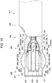
- Fig. 11 is a schematic partial longitudinal sectional view of the distal end portion of the insertion portion of the ultrasonic endoscope shown in Figs. 9 and 10 .
- the ultrasonic endoscope 212 is a radial-type ultrasonic endoscope that includes an ultrasonic transducer unit 246 in the ultrasonic observation portion 236 of the distal end portion 240.
- the ultrasonic transducer unit 246 includes an ultrasonic transducer array 250 in which a plurality of ultrasonic transducers 248 are cylindrically arranged.
- the ultrasonic observation portion 236 is disposed on the distal end side of the ultrasonic endoscope 212 relative to the endoscopic observation portion 238.
- the ultrasonic endoscope 212 may include a mechanism for leading out treatment tools, such as forceps, a puncture needle, and a high-frequency knife.
- a treatment tool lead-out port (not shown), from which these treatment tools are led out, may be formed on the distal end side or on the proximal end side of the ultrasonic endoscope 212 relative to the plurality of ultrasonic transducers 248.
- the endoscopic observation portion 238 of the ultrasonic endoscope 212 has a structure similar to that of the endoscopic observation portion 38 of the ultrasonic endoscope 12 of the first embodiment shown in Figs. 2 and 3 .
- the endoscopic observation portion 238 has an observation window (88), an objective lens (90), a solid-state imaging element (92), an illumination window (94), a cleaning nozzle (96), a wiring cable (98), and the like.
- the ultrasonic observation portion 236 is composed of the ultrasonic transducer unit 246, an exterior member 241 for attaching and holding the ultrasonic transducer unit 246, and the cable portion 70 including the plurality of coaxial cables 71 that are wired to the ultrasonic transducer unit 246.
- the ultrasonic transducer unit 246 has the ultrasonic transducer array 250 in which the plurality of ultrasonic transducers 248 are cylindrically arranged, an electrode portion 200 that is electrically continuous with the ultrasonic transducer array 250, a backing material layer 252 that supports the ultrasonic transducers 248 of the ultrasonic transducer array 250 from a side of a surface on the central side of the ultrasonic transducer unit 246 (inner surfaces of the ultrasonic transducer 248), an acoustic matching layer 264 that is laminated on a side opposite to the backing material layer 252 with respect to the ultrasonic transducer array 250 (outer side of the ultrasonic transducer array 250), and an acoustic lens 266 that is laminated on a side opposite to the ultrasonic transducer array 250 with respect to the acoustic matching layer 264 (outer side of the acoustic matching layer 264).
- the ultrasonic transducer array 250 in which the plurality of
- the ultrasonic transducers 248, the ultrasonic transducer array 250, the backing material layer 252, the acoustic matching layer 264, the acoustic lens 266, and the laminated body 247 according to the present embodiment differ in shape but do not differ in structure and function from the ultrasonic transducers 48, the ultrasonic transducer array 50, the backing material layer 52, the acoustic matching layer 64, the acoustic lens 66, and the laminated body 47 of the first embodiment shown in Figs. 2 and 3 . Therefore, description of these elements will be omitted.
- the ultrasonic transducer unit 246 has an annular plate 202 that is disposed in such a way that a side surface thereof on the distal end side of the ultrasonic endoscope 212 contacts a side surface of the backing material layer 252 on the distal end side of the ultrasonic endoscope 212 and that fixes the position of a cylindrical member 204 (described below); a support plate 203 that is a disk-shaped plate having an outside diameter larger than the inside diameter of the annular plate 202; the cylindrical member 204 that contacts a surface of the backing material layer 252 on a side opposite to the ultrasonic transducer array 250 (inside of the backing material layer 252), that is joined to the support plate 203 at an end surface thereof on the distal end side of the ultrasonic endoscope 212, and that supports the laminated body 247; a wiring board 254 that is disposed on an outer peripheral portion of the cylindrical member 204 on the proximal end side of the ultrasonic endoscope 212 relative to the backing material layer 25
- the electrode portion 200 of the ultrasonic transducer unit 246 has individual electrodes 200a for transmitting and receiving voltage signals, such as drive signals and ultrasonic echo signals, to and from the plurality of ultrasonic transducers 248, and a transducer ground 200b that is a ground electrode for the plurality of ultrasonic transducers 248.
- voltage signals such as drive signals and ultrasonic echo signals
- each of the individual electrodes 200a is disposed so as to be lead out from an end portion of the ultrasonic transducer 248 on an inner side and on the proximal end side of the ultrasonic transducer 248 to an end surface of the backing material layer 252 on the proximal end side, and the individual electrode 200a is electrically connected to a plurality of electrode pads 205 (described below) of the wiring board 254.
- the transducer ground 200b is electrically connected to a grounded portion in the ultrasonic endoscope 212 by using a lead wire or the like.
- the plurality of electrode pads 205 which are electrically connected to the plurality of individual electrodes 200a of the electrode portion 200, are electrically continuous with the signal wires 71a of the plurality of coaxial cables 71, the plurality of individual electrodes 200a of the electrode portion 200 are electrically continuous with the signal wires 71a of the coaxial cables 71.
- the transducer ground 200b is a ground electrode for the plurality of ultrasonic transducers 248, preferably, the ground potentials thereof are the same potential.
- the transducer ground 200b is a common electrode for the plurality of ultrasonic transducers 248.
- the transducer ground 200b need not be electrically continuous with the shield layers 71c of the plurality of coaxial cables 71.
- the positions of the plurality of individual electrodes 200a and the transducer ground 200b are not limited to those shown in Fig. 10 , provided that the individual electrodes 200a and the transducer ground 200b can be connected to the signal wires and the ground portion.
- the positions may be on parts of the ultrasonic transducer 248 on the distal end side of the ultrasonic endoscope 212, or over the entireties of the inner surface and the outer surface of the ultrasonic transducer 248; or the positions may be changed as appropriate in accordance with the structure of the ultrasonic observation portion 236.
- the wiring board 254 of the ultrasonic transducer unit 246 is disposed on an outer peripheral portion of the cylindrical member 204 on the proximal end side of the backing material layer 252 and is electrically connected to the electrode portion 200.
- the wiring board 254 has the plurality of electrode pads 205 that are disposed in a portion thereof on the distal end side of the ultrasonic endoscope 212 (distal end side of the wiring board 254), a wiring portion 256 that is disposed in a portion thereof on the proximal end side of the wiring board 254 relative to the plurality of electrode pads 205, and a ground portion 260 that is disposed in a portion of the wiring board 254 on the most proximal end side.
- the electrode pads 205 are members each of which is to be connected to a corresponding one of the plurality of individual electrodes 200a of the electrode portion 200.
- the wiring portion 256 is composed of a plurality of connection portions 258 that are terminals that are electrically continuous with the plurality of electrode pads 205 via wiring (not shown) formed in the wiring board 254 and that are electrically connected to the signal wires 71a of the plurality of coaxial cables 71.
- the ground portion 260 is electrically connected to the shield layers 71c of the plurality of coaxial cables 71.
- the wiring board 254 may be any appropriate member that can electrically connect the plurality of individual electrodes 200a of the electrode portion 200 and the signal wires 71a of the plurality of coaxial cables 71.
- An FPC may be used as the wiring board 254, or the wiring board 254 may have a cylindrical shape that surrounds the cylindrical member 204.
- a plurality of the wiring boards 254 may be disposed, and the wiring boards 254 may be arranged side by side so as to surround the cylindrical member 204.
- the support plate 203 of the ultrasonic transducer unit 246 is a disk-shaped plate that is disposed in contact with a surface of the annular plate 202 on a side opposite to the backing material layer 252 and that has an outside diameter larger than the inside diameter of the annular plate 202.
- the support plate 203 fixes the positions of the annular plate 202 and the cylindrical member 204. Therefore, in order to fix the position of the cylindrical member 204, preferably, the support plate 203 is joined to the cylindrical member 204, or may be a member that is integrated with the cylindrical member 204.
- the support plate 203 in order to fix the position of the cylindrical member 204, preferably, the support plate 203 is joined also to the annular plate 202.
- the shape of the support plate 203 is not limited to a disk-like shape and may be any appropriate shape, such as a polygonal shape, provided that the support plate 203 can fix the positions of the annular plate 202 and the cylindrical member 204.
- the cylindrical member 204 of the ultrasonic transducer unit 246 is disposed in contact with the inner surface of the backing material layer 252, the inner surface of the annular plate 202, and a surface of the support plate 203 on a side opposite to the distal end side of the ultrasonic endoscope, and fixes the laminated body 247.
- Parts of the plurality of coaxial cables 71 of the cable portion 70 on the distal end side are disposed in a space in the cylindrical member 204 on the proximal end side and on the central side of the ultrasonic transducer unit 246 (inside of the cylindrical member 204).
- a plurality of slits 206 for leading out the plurality of coaxial cables 71 toward the outer peripheral side of the cylindrical member 204, are formed in a portion of the cylindrical member 204 on the proximal end side of the backing material layer 252.
- the cylindrical member 204 may be made of any appropriate material such as a metal or a resin, provided that the cylindrical member 204 can support the laminated body 247.
- the copper foil 262 of the ultrasonic transducer unit 246 is a member that is disposed along the side surfaces of the plurality of ultrasonic transducers 248 and the backing material layer 252 on the proximal end side and that conducts heat generated in the plurality of ultrasonic transducers 48. Moreover, in the example shown in Figs. 10 and 11 , a part of the copper foil 262 is extended and is electrically connected to the shield member 73 of the cable portion 70. Therefore, heat generated in the plurality of ultrasonic transducers 248 can be dissipated to the proximal and side of the cable portion 70 via the shield member 73 of the cable portion 70.
- the extended portion of the copper foil 262 may be made of a material different from that of a portion of the copper foil 262 that is disposed along the ultrasonic transducer array 250 and the backing material layer 252. That is, provided that the copper foil 262 and the shield member 73 of the cable portion 70 can be electrically or thermally connected to each other, a portion of the copper foil 262 that contacts the ultrasonic transducer array 250 and the backing material layer 252 may be connected to the shield member 73 of the cable portion 70 by using a lead wire or a mesh-shaped electroconductive member.
- the copper foil 262 may be replaced with a metal member made of a metal having high heat conductivity, such as aluminum, gold, or silver; a heat conductive silicone sheet; or the like.
- a metal member made of a metal having high heat conductivity, such as aluminum, gold, or silver; a heat conductive silicone sheet; or the like.
- the copper foil 262 or a heat conductive member that is used instead of the copper foil 262 can be grounded. In this case, noise received from the outside by the copper foil 262 or a heat conductive member that is used instead of the copper foil 262 can be prevented from entering the plurality of ultrasonic transducers 248.
- the second heat conductive member 80 is disposed between the first insulation tube 74 and the connection pipe 76 of the cable portion 70. Therefore, heat that has been conducted from the copper foil 262 to the shield member 73 of the cable portion 70 can be conducted to the connection pipe 76 and dissipated.
- Fig. 11 which is a figure that is simplified for convenience of description as with Fig. 4 , only the ultrasonic transducer unit 246 and the cable portion 70 are illustrated, and the other elements are omitted.
- the plurality of electrode pads 205 of the wiring board 254 are disposed on the distal end side of the wiring board 254 and are electrically connected to the plurality of individual electrodes 200a of the electrode portion 200 by using the wiring cable 208 or the like.
- the plurality of electrode pads 205 are each electrically continuous with a corresponding one of the plurality of connection portions 258 of the wiring portion 256 via wiring (not shown) formed in the wiring board 254.
- the electrode pads 205 may be arranged in multiple rows.
- Wiring means for wiring the plurality of electrode pads 205 and the plurality of individual electrodes 200a is not limited to the wiring cable 208 illustrated in the figures.
- Known wiring means such as lead wires or a FPC, may be used, provided that the wiring means can electrically connect the plurality of electrode pads 205 and the plurality of individual electrodes 200a.
- the wiring portion 256 of the wiring board 254 is composed of the plurality of connection portions 258, which are terminals each of which is wired to a corresponding one of the signal wires 71a of the plurality of coaxial cables 71 of the cable portion 70.
- the wiring portion 256 is disposed between the plurality of electrode pads 205 and the ground portion 260 of the wiring board 254.
- the total number of the plurality of connection portions 258 of the wiring portion 256 is at least larger than or equal to the total number of the plurality of electrode pads 205.
- connection portions 258 may be arranged in multiple rows.
- wiring portions between the signal wires 71a of the plurality of coaxial cables 71 of the cable portion 70 and the plurality of connection portions 258 of the wiring portion 256 are covered by a filler (not shown) made of an insulating resin or the like, in order to prevent wire breakage at the wiring portions.
- the ground portion 260 of the wiring board 254 is an electroconductive member that is disposed on the proximal end side of the wiring board 254 and that is electrically connected to the shield layers 71c of the plurality of coaxial cables 71 of the cable portion 70.
- the shield layers 71c of the plurality of coaxial cables 71 are electrically connected to the ground portion 260. Accordingly, in order to make the ground potentials of the shield layers 71c of the coaxial cables 71 be the same potential, preferably, ground portions 260 to which the shield layers 71c of the coaxial cables 71 are electrically connected are electrically continuous with each other.
- the ground portion 260 may have an annular shape so as to surround the cylindrical member 204.
- the ground portions 260 of the wiring boards 254 may be electrically connected to each other by using lead wires or the like.
- the ground potentials of the plurality of ultrasonic transducers 248 can be made to be the same potential.
- heat generated in the plurality of ultrasonic transducers 248 can be dissipated to the shield member 73 and the connection pipe 76 of the cable portion 70.
- the ultrasonic endoscope 212 having the radial-type ultrasonic transducer unit 246 can have a heat dissipation structure similar to that described in the first embodiment.
- the radial-type ultrasonic transducer unit 246 shown in Figs. 10 and 11 is connected to the cable portion 79 of the example of the first embodiment shown in Fig. 6 . Therefore, in the structure shown in Fig. 12 , as in the structure of the example of the first embodiment shown in Fig. 6 , because the second heat conductive member 81 of the cable portion 79 has the outward flange 81a, the heat dissipation path from the second heat conductive member 81 to the connection pipe 76 is large, and the heat dissipation efficiency is improved.
- connection pipe 76 serves as a retainer of the connection pipe 76, a portion of the cable portion 70 inside of the connection pipe 76 can be prevented from moving toward the distal end side relative to the connection pipe 76.
- the radial-type ultrasonic transducer unit 246 shown in Figs. 10 and 11 is connected to the cable portion 82 of the example of the first embodiment shown in Fig. 7 . Therefore, with the structure shown in Fig. 13 , as in the example of the structure of the first embodiment shown in Fig. 7 , the heat dissipation effect can be improved.
- the radial-type ultrasonic transducer unit 246 shown in Figs. 10 and 11 is connected to the cable portion 85 of the example of the first embodiment shown in Fig. 8 . Therefore, with the structure shown in Fig. 14 , as with the example of the structure of the first embodiment shown in Fig. 8 , the third heat conductive member 86 is disposed so as to fill a space between the first insulation tube 74, and at least a part of the connection pipe 76 and the second insulation tube 78.
- heat that is generated in the plurality of ultrasonic transducers 248 and conducted to the shield member 73 of the cable portion 85 via the copper foil 262 can be dissipated to the connection pipe 76 and the third heat conductive member 86. Accordingly, as with the example of the first embodiment shown in Fig. 8 , heat dissipation paths can be increased, and the heat dissipation efficiency can be improved.
- ultrasonic endoscopes each having a heat dissipation structure according to the present invention have been described.
- the present invention is not limited to the examples described above, and, as a matter of course, may be improved or modified in various ways within the spirit and scope of the present invention.
- the embodiments and the plurality of examples described above may be used in combination as appropriate.
Description
- The present invention relates to ultrasonic endoscopes, and, in particular, to an ultrasonic endoscope that has, in a distal end portion thereof, a structure for dissipating heat generated in very small ultrasonic transducers that are used for an ultrasonic endoscope that is inserted into a body cavity.
- An ultrasonic endoscope is an endoscope that has an ultrasonic observation portion in a distal end portion thereof mainly for the purpose of observing the gallbladder or the pancreas via digestive tract. In the distal end portion of the ultrasonic endoscope, there are heat-generating elements such as ultrasonic transducers and a light source of the endoscope. Because the distal end portion of the ultrasonic endoscope directly contacts the inside of a living body such as a human body, for safety reasons such as prevention of a moderate-temperature burn, it is required that the surface temperature of an insertion portion be lower than or equal to a predetermined temperature.
- Moreover, the distal end portion of the ultrasonic endoscope has, in addition to the ultrasonic observation portion, an illumination unit, a suction port, and the like, as with an ordinary endoscope that does not have an ultrasonic observation portion. Therefore, the outside diameter of the distal end portion of the ultrasonic endoscope is large, which causes reduction in operability of the ultrasonic endoscope and increase of a burden on a patient into whom the distal end portion of the ultrasonic endoscope is inserted.
- For this reason, an ultrasonic endoscope that has means for lowering the surface temperature of the distal end portion while maintaining the small size of the distal end portion is required. Therefore, in recent years, various proposals for dissipating heat generated in the ultrasonic transducers have been made (see
JP2009-240755A JP2009-297352A -
JP2009-240755A - An ultrasonic probe disclosed in
JP2009-297352A -
EP0782125A2 discloses an apparatus for transferring heat from transducer array of ultrasonic probe. The cable components are used as heat pipes which conduct heat out of the probe handle. These heat pipes are coupled to an internal heat pipe which is in heat conductive relationship with the transducer pallet. A heat conductive structure can be embedded in the overall shield braid of the cable. Suitable heat conductive structures include a thread or wire, as well as narrow tubing filled with heat conductive fluid. -
US 2009/062656 A1 discloses a backing material, ultrasonic probe, ultrasonic endoscope, ultrasonic diagnostic apparatus, and ultrasonic endoscopic apparatus. The backing material is provided on a back face of at least one vibrator for transmitting and/or receiving ultrasonic waves in an ultrasonic probe, and includes: a backing base material containing a polymeric material; and a heat conducting fiber provided in the backing base material, having a larger coefficient of thermal conductivity than that of the backing base material, and running through without disconnection from a first face of the backing material in contact with the at least one vibrator to a second face different from the first face. - The technology disclosed in
JP2009-240755A JP2009-240755A - In the technology disclosed in
JP2009-297352A - Examples of means that need to be used to improve the diagnosis accuracy of the ultrasonic observation portion in the ultrasonic endoscope or the ultrasonic probe disclosed in
JP52009-240755A JP2009-297352A - There is a problem in that, although improvement of accuracy in ultrasonic diagnosis is required in addition to improvement of operability and relieving of a burden on a patient, it is very difficult to efficiently dissipate heat generated in the distal end portion of the ultrasonic endoscope while maintaining the small diameter of the insertion portion of the ultrasonic endoscope and maintaining the small size of the distal end portion.
- An object of the present invention is to solve the problems of the existing technology described above and to provide an ultrasonic endoscope that has a heat dissipation structure that can efficiently dissipate heat generated in ultrasonic transducers while maintaining the small diameter of an insertion portion and maintaining the small size of a distal end portion, and, as a result, that can improve the diagnosis accuracy in ultrasonic observation.
- In order to achieve the object, there is provided an ultrasonic endoscope according to claim 1 of the appended claims.
- Preferably, the second heat conductive member fills at least a part of a space between the first insulation tube and the connection pipe.
- Preferably, the second heat conductive member is a cylindrical member that is disposed between the first insulation tube and the connection pipe.
- Preferably, the second heat conductive member has a thick portion at an end portion thereof on a distal end side of the ultrasonic endoscope, the thick portion being thicker than a portion thereof that is disposed between the first insulation tube and the connection pipe; and the thick portion contacts an end surface of the connection pipe on the first heat conductive member side.
- Preferably, the second heat conductive member includes a cylindrical portion and the thick portion, the cylindrical portion being disposed between the first insulation tube and the connection pipe, and the thick portion is an outward flange that has a cylindrical shape having an outside diameter larger than or equal to an inside diameter of the connection pipe.
- Preferably, the cable portion has a jacket of one layer outside of the shield member, and the jacket of the cable portion is removed at least at a portion that is covered by the second heat conductive member together with the first insulation tube.
- Preferably, the jacket of the cable portion is removed on the distal end side of the connection pipe and the shield member is exposed; at a portion where the jacket is removed and the shield member is exposed to the first insulation tube, a part of the first insulation tube is removed, and the shield member is exposed to the outside; and the second heat conductive member contacts the portion where the shield member is exposed to the outside, covers the removed part of the first insulation tube, and contacts the distal end side of the connection pipe.
- Preferably, the ultrasonic endoscope according to the present invention further includes an insulation layer that is disposed outside of the connection pipe.
- Preferably, the ultrasonic endoscope according to the present invention further includes a third heat conductive member that fills a space between the first insulation tube, and a portion of the connection pipe on the proximal end side and the second insulation tube.
- With the present invention, because the distal end portion of the ultrasonic endoscope has a heat dissipation structure for dissipating heat toward the proximal end side of the ultrasonic endoscope, it is possible to efficiently dissipate heat that is generated due to driving of the ultrasonic transducers, and it is possible to increase the output power of the ultrasonic transducers without increasing a burden on a patient.
-
-
Fig. 1 is a schematic view of an example of the structure of an ultrasonic inspection system that uses an ultrasonic endoscope to which an ultrasonic transducer unit according to the present invention is applied; -
Fig. 2 is a partial enlarged plan view of a distal end portion of an insertion portion of the ultrasonic endoscope shown inFig. 1 ; -
Fig. 3 is a partial longitudinal sectional view taken along line III-III inFig. 2 , illustrating the insertion portion of the distal end portion of the ultrasonic endoscope shown inFig. 2 ; -
Fig. 4 is a schematic partial longitudinal sectional view of the distal end portion of the insertion portion of the ultrasonic endoscope shown inFigs. 1 to 3 ; -
Fig. 5 is a schematic cross-sectional view of a coaxial cable of a cable portion shown inFigs. 3 and4 ; -
Fig. 6 is a partial longitudinal sectional view of another example of a distal end portion of an insertion portion of an ultrasonic endoscope according to a first embodiment of the present invention; -
Fig. 7 is a partial longitudinal sectional view of another example of the distal end portion of the insertion portion of the ultrasonic endoscope according to the first embodiment of the present invention; -
Fig. 8 is a partial longitudinal sectional view of another example of the distal end portion of the insertion portion of the ultrasonic endoscope according to the first embodiment of the present invention; -
Fig. 9 is a partial enlarged plan view of a distal end portion of an insertion portion of an ultrasonic endoscope according to a second embodiment of the present invention; -
Fig. 10 is a partial longitudinal sectional view taken along line X-X inFig. 9 , illustrating the distal end portion of the ultrasonic endoscope shown inFig. 9 ; -
Fig. 11 is a schematic partial longitudinal sectional view of the ultrasonic endoscope shown inFigs. 9 and10 ; -
Fig. 12 is a partial longitudinal sectional view of another example of the distal end portion of the insertion portion of the ultrasonic endoscope according to the second embodiment of the present invention; -
Fig. 13 is a partial longitudinal sectional view of another example of the distal end portion of the insertion portion of the ultrasonic endoscope according to the second embodiment of the present invention; and -
Fig. 14 is a partial longitudinal sectional view of another example of the distal end portion of the insertion portion of the ultrasonic endoscope according to the second embodiment of the present invention. - Hereinafter, an ultrasonic endoscope according to the present invention will be described in detail based on preferred embodiments illustrated in the drawings.
-
Fig. 1 is a schematic view of an example of the structure of an ultrasonic inspection system that uses the ultrasonic endoscope according to the present invention. - An
ultrasonic inspection system 10 shown inFig. 1 is a system that enables observation of the gallbladder or the pancreas, which is difficult to observe by using ultrasonic inspection from the body surface of a subject such as a patient, via digestive tract such as the esophagus, the stomach, the duodenum, the small intestine, the large intestine, and the like, each of which is a body cavity of the subject. Theultrasonic inspection system 10 inserts an ultrasonic endoscope according to the present invention, which has an ultrasonic observation portion that captures an ultrasound tomographic image (hereinafter, referred to an ultrasound image) and an endoscopic observation portion that captures an endoscopic optical image (hereinafter, referred to as an endoscopic image), into a body cavity of a subject and captures the ultrasound image of an observation target site of the subject while observing the endoscopic image of the subject. - As illustrated in
Fig. 1 , theultrasonic inspection system 10 includes anultrasonic endoscope 12 having a heat dissipation structure that is a feature of the present invention, anultrasonic processor device 14 that generates an ultrasound image, anendoscope processor device 16 that generates an endoscopic image, alight source device 18 that supplies illumination light for illuminating the inside of a body cavity to theultrasonic endoscope 12, and amonitor 20 that displays the ultrasound image and/or the endoscopic image. - The
ultrasonic inspection system 10 further includes awater supply tank 21a that stores cleaning water or the like and asuction pump 21b that suctions a suction object (including the supplied cleaning water and the like) in a body cavity. Although not illustrated, theultrasonic inspection system 10 may include a supply pump or the like that supplies cleaning water in thewater supply tank 21a or a gas, such as outside air, to a pipe line (not shown) in theultrasonic endoscope 12. - First, the
ultrasonic endoscope 12 shown inFig. 1 has, at the distal end thereof, anultrasonic observation portion 36, having a heat dissipation structure that is a feature of the present invention, and anendoscopic observation portion 38. Theultrasonic endoscope 12 captures an ultrasound image (echo signal) and an endoscopic image (image signal) of the inside of the body cavity. - The
ultrasonic endoscope 12 is composed of aninsertion portion 22 that includes theultrasonic observation portion 36 and theendoscopic observation portion 38 at an end thereof and that is inserted into a body cavity of a subject; anoperating unit 24 that is connected to a proximal end portion of theinsertion portion 22 and with which an operator, such as a doctor or an engineer, performs an operation; and auniversal cord 26 one end of which is connected to the operatingunit 24. - The operating
unit 24 has an air/water supply button 28a, for opening or closing an air/water supply pipe line (not shown) from thewater supply tank 21a, and asuction button 28b, for opening or closing a suction pipe line (not shown) from thesuction pump 21b, which are arranged side by side. Moreover, the operatingunit 24 has a pair of angle knobs 29 and a treatment tool insertion port 30 (forceps port). - Here, the
water supply tank 21a stores cleaning water or the like that is supplied to the air/water supply pipe line in theultrasonic endoscope 12 for cleaning theendoscopic observation portion 38 of theultrasonic endoscope 12 and the like. The air/water supply button 28a is used to eject a gas such as air and water such as cleaning water, which are supplied from thewater supply tank 21a through the air/water supply pipe line, from theendoscopic observation portion 38 on the distal end side of theinsertion portion 22. - The
suction pump 21b suctions a suction pipe line (not shown) to suction a suction object (including supplied cleaning water and the like) in a body cavity from the distal end side of theultrasonic endoscope 12. Thesuction button 28b is used to suction a suction object in a body cavity from the distal end side of theinsertion portion 22 by using a suction force of thesuction pump 21b. - The treatment
tool insertion port 30 is used to insert a treatment tool, such as forceps, a puncture needle, a high-frequency knife, or the like. - At the other end portions of the
universal cord 26, anultrasound connector 32a connected to theultrasonic processor device 14, anendoscope connector 32b connected to theendoscope processor device 16, and alight source connector 32c connected to thelight source device 18 are provided. Theultrasonic endoscope 12 is removably connected to theultrasonic processor device 14, theendoscope processor device 16, and thelight source device 18 via theconnectors water supply tube 34a, for connecting to thewater supply tank 21a, asuction tube 34b, for connecting thesuction pump 21b, and the like are connected to thelight source connector 32c. - The
insertion portion 22 is composed of, in order from the distal end side, a distal end portion 40 (distal end rigid portion) that is formed of a rigid member and that has theultrasonic observation portion 36 and theendoscopic observation portion 38; a bendingportion 42 that is connected to the proximal end side of thedistal end portion 40, that is formed by coupling a plurality of bending pieces, and that can be bent freely; and asoft portion 43 that couples the proximal end side of the bendingportion 42 and the distal end side of the operatingunit 24 to each other, that has a thin and elongated shape, and that has flexibility. - The bending
portion 42 is remote-controlled so as to be bent by rotating the pair of angle knobs 29 of the operatingunit 24. Therefore, thedistal end portion 40 can be directed in a desired direction. - A balloon, which covers the
ultrasonic observation portion 36 and into which an ultrasound transmission medium (such as water, oil, or the like) is injected, may be removably attached to thedistal end portion 40. Because ultrasound and an echo signal are considerably attenuated in air, by inflating the balloon by injecting the ultrasound transmission medium into the balloon and causing the balloon to contact an observation target site, it is possible to remove air from a space between an ultrasonic transducer array 50 (seeFigs. 2 to 4 ) of theultrasonic observation portion 36 and the observation target site and to prevent attenuation of the ultrasound and the echo signal. - The
ultrasonic processor device 14 generates and supplies an ultrasound signal (data), for generating ultrasound, to the ultrasonic transducer array 50 (seeFigs. 2 to 4 ) of anultrasonic transducer unit 46 of theultrasonic observation portion 36 of thedistal end portion 40 of theinsertion portion 22 of theultrasonic endoscope 12. Moreover, theultrasonic processor device 14 receives and obtains an echo signal (data), which is reflected from an observation target site to which ultrasound is emitted, with theultrasonic transducer array 50; and generates an ultrasound image, which is to be displayed on themonitor 20, by performing various types of signal (data) processing on the obtained echo signal. - The
endoscope processor device 16 receives and obtains a captured image signal (data) that is obtained from an observation target site, which is illuminated with illumination light from thelight source device 18, in theendoscopic observation portion 38 of thedistal end portion 40 of theinsertion portion 22 of theultrasonic endoscope 12. Theendoscope processor device 16 generates an endoscopic image, which is to be displayed on themonitor 20, by performing various types of signal (data) processing on the obtained image signal. - The
processor devices - In order to obtain an image signal by capturing an image of an observation target site in a body cavity by using the
endoscopic observation portion 38 of theultrasonic endoscope 12, thelight source device 18 generates illumination light, such as white light or a specific wavelength light, composed of three primitive color light that is, for example, red light (R), green light (G), and blue light (B), and supplies the illumination light to theultrasonic endoscope 12. The illumination light propagates via a light guide (not shown) or the like in theultrasonic endoscope 12, is emitted from theendoscopic observation portion 38 of thedistal end portion 40 of theinsertion portion 22 of theultrasonic endoscope 12, and illuminates the observation target site in the body cavity. - The
monitor 20 receives image signals generated by theultrasonic processor device 14 and theendoscope processor device 16 and displays an ultrasound image and an endoscopic image. An image to be displayed on themonitor 20 can be switched between the ultrasound image and the endoscopic image, and both of these images can be simultaneously displayed on themonitor 20. A monitor for displaying the ultrasound image and a monitor for displaying an endoscopic image may be independently provided, or the ultrasound image and the endoscopic image may be displayed in any other appropriate form. - Next, referring to
Figs. 2 to 4 , the structure of the distal end portion of the insertion portion of the ultrasonic endoscope will be described in detail. -
Fig. 2 is a partial enlarged plan view of the distal end portion of the insertion portion of the ultrasonic endoscope shown inFig. 1 and the vicinity of the distal end portion.Fig. 3 is a partial longitudinal sectional view taken along line III-III inFig. 2 , illustrating the distal end portion of the insertion portion of the ultrasonic endoscope shown inFig. 2 that is cut along the centerline in the longitudinal direction thereof.Fig. 4 is a schematic partial longitudinal sectional view of a heat dissipation structure of the distal end portion of the insertion portion of the ultrasonic endoscope shown inFigs. 1 to 3 . - As illustrated in
Figs. 2 , and3 , thedistal end portion 40 of theultrasonic endoscope 12 has theultrasonic observation portion 36, for obtaining an ultrasound image, on the distal end side; theendoscopic observation portion 38, for obtaining an endoscopic image, on the proximal end side; and a treatment tool lead-outport 44 between these. Theobservation portions exterior member 41 that is the body of thedistal end portion 40 of theultrasonic endoscope 12 and that is made of a rigid material such as a rigid resin. - In the example shown in
Fig. 2 , the treatment tool lead-outport 44 is formed between theultrasonic observation portion 36 and theendoscopic observation portion 38. However, the present invention is not particularly limited to the example illustrated in the figure. The treatment tool lead-outport 44 may be formed in theendoscopic observation portion 38 or may be formed on the proximal end side (the bendingportion 42 side) relative to theendoscopic observation portion 38. - As illustrated in
Figs. 2 and3 , theultrasonic observation portion 36 is composed of theultrasonic transducer unit 46, theexterior member 41 for attaching and holing theultrasonic transducer unit 46, and acable portion 70 that includes a plurality ofcoaxial cables 71 that are connected to theultrasonic transducer unit 46. - The
ultrasonic transducer unit 46 has theultrasonic transducer array 50 that is composed of a plurality ofultrasonic transducers 48, abacking material layer 52 that supports theultrasonic transducers 48 of theultrasonic transducer array 50 from the lower surface side, awiring board 54 that is embedded in thebacking material layer 52 and that is electrically connected to the plurality ofultrasonic transducers 48, a copper foil 62 (first heat conductive member) that is disposed along a side surface of thebacking material layer 52 in the width direction and end surfaces of the plurality ofultrasonic transducers 48 in the longitudinal direction, and afiller layer 68 that fills a space between theexterior member 41 and thebacking material layer 52. - In the example shown in the figures, in the
backing material layer 52, in thewiring board 54 that is electrically connected to individual electrodes (not shown) of the plurality ofultrasonic transducers 48, awiring portion 56 that has a plurality ofconnection portions 58, to whichsignal wires 71a at one ends of the plurality ofcoaxial cables 71 are connected, is provided. Here, drive voltage signals to the plurality ofultrasonic transducers 48 and ultrasonic echo signals (voltage signals) from the plurality ofultrasonic transducers 48 are applied to the individual electrodes of the plurality ofultrasonic transducers 48. The plurality ofcoaxial cables 71 are electrically connected to theultrasonic processor device 14 at the other ends thereof. Thesignal wires 71a of the plurality ofcoaxial cables 71 are each electrically connected to a corresponding one of the plurality ofultrasonic transducers 48. Moreover, thewiring board 54 has, in thewiring portion 56, aground portion 60 that is electrically connected, via a lead wire or the like, to a transducer ground (not shown) that is a ground electrode of theultrasonic transducer array 50. Theground portion 60 may be connected to shieldlayers 71c of the plurality ofcoaxial cables 71. - The
ultrasonic transducer unit 46 further has anacoustic matching layer 64 that is laminated on theultrasonic transducer array 50, and anacoustic lens 66 that is laminated on theacoustic matching layer 64. That is, theultrasonic transducer unit 46 is composed of alaminated body 47 in which theacoustic lens 66, theacoustic matching layer 64, theultrasonic transducer array 50, and thebacking material layer 52 are laminated. - The
acoustic matching layer 64 performs acoustic impedance matching between a subject, such as a human body, and theultrasonic transducers 48. - The
acoustic lens 66, which is attached onto theacoustic matching layer 64, causes ultrasound, which is emitted from theultrasonic transducer array 50, to converge toward an observation target site. Theacoustic lens 66 is made of, for example, a silicone-based resin (a millable silicone rubber (HTV rubber), a liquid silicone rubber (RTV rubber), or the like), a butadiene-based resin, a polyurethane-based resin, or the like. In order to perform acoustic impedance matching between a subject and theultrasonic transducers 48 by using theacoustic matching layer 64 and to increase transmittance of ultrasound, powder of titanium oxide, alumina, silica, or the like is mixed into theacoustic lens 66 as necessary. - The
cable portion 70 of theultrasonic observation portion 36 has a heat dissipation structure that is the feature of the present invention. As illustrated inFig. 4 , thecable portion 70 has the plurality ofcoaxial cables 71 disposed on the central side, an insulatingjacket 72a that covers the plurality ofcoaxial cables 71, anelectroconductive shield member 73 that is disposed so as to cover thejacket 72a and that can be grounded to the housing of theultrasonic endoscope 12, and ajacket 72b that covers the outside of theshield member 73. Thecable portion 70 has afirst insulation tube 74 for covering and protecting the outer periphery of theouter jacket 72b; anelectroconductive connection pipe 76 that is disposed on the proximal end side of the cable portion 70 (a side opposite to the laminated body 47) and that covers at least a part of thefirst insulation tube 74; and asecond insulation tube 78 that is connected to an end portion of theconnection pipe 76 on a side opposite to theultrasonic transducer unit 46 and that covers a connection portion with theconnection pipe 76 and thefirst insulation tube 74 on theuniversal cord 26 side relative to theconnection pipe 76. Moreover, a second heatconductive member 80 is disposed so as to fill at least a part of a space between thefirst insulation tube 74 and theconnection pipe 76. Theshield member 73 of thecable portion 70 may be made from a metal member or the like, provided that theshield member 73 covers the plurality ofcoaxial cables 71 from the outside and has electroconductivity. InFig. 4 , which is a figure simplified for convenience of description, only theultrasonic transducer array 50, thebacking material layer 52, thecopper foil 62, thewiring board 54, and thecable portion 70 are illustrated, and other members are omitted. - Here, the meaning of "grounding" in the present invention is not limited to causing the potential of an electroconductive member to be zero, and also includes a case where, for example, the voltage of an electroconductive member is maintained at a predetermined low voltage by connecting the electroconductive member to a member having a large electric capacity.
- The plurality of
coaxial cables 71 are electrically connected to the plurality ofconnection portions 58 of thewiring portion 56 of thewiring board 54. Moreover, theshield member 73 is thermally connected to thecopper foil 62 of theultrasonic transducer unit 46 at an end portion thereof on theultrasonic transducer unit 46 side. Therefore, in order from the end portion of thecable portion 70 on theultrasonic transducer unit 46 side, thecoaxial cables 71 and theinner jacket 72a are exposed in theultrasonic observation portion 36. At a portion of the exposedinner jacket 72a that is adjacent to a side opposite to theultrasonic transducer unit 46, theouter jacket 72b is removed and theshield member 73 is exposed, and the exposedshield member 73 and thecopper foil 62 are connected to each other. - The
ultrasonic transducer array 50 of theultrasonic transducer unit 46 shown inFigs. 2 and3 is, for example, an array of 48 to 192 channels (CH) that is composed of 48 to 192 pieces of rectangular-parallelepiped-shapedultrasonic transducers 48 that are arranged in an outwardly convex arc shape. - That is, the
ultrasonic transducer array 50 is formed by arranging the plurality ofultrasonic transducers 48, for example, in a one-dimensional array shape at a predetermined pitch as in the example shown in the figures. Thus, theultrasonic transducers 48 of theultrasonic transducer array 50 are arranged at a regular pitch in the axial direction of the distal end portion 40 (the longitudinal axial direction of the insertion portion 22) in a convexly curved shape and are sequentially driven on the basis of drive signals that are input from theultrasonic processor device 14. Thus, convex electronic scan is performed over a scan range that is a range in which theultrasonic transducers 48 are arranged as shown inFig. 2 . - The length of the
ultrasonic transducer array 50 in the width direction of theultrasonic transducer array 50, that is, the longitudinal direction of the ultrasonic transducers 48 (elevation (EL) direction) is smaller than the length of theultrasonic transducer array 50 in a direction parallel to the bottom surface of the backing material layer 52 (the azimuth (AZ) direction). Theultrasonic transducer array 50 is disposed so as to be inclined in such a way that the back end side thereof protrudes. Theultrasonic transducer 48 has a structure in which, for example, electrodes are formed on both surfaces of a thick piezoelectric film of lead zirconate titanate (PZT), polyvinylidene fluoride (PVDF), or the like. An electrode of theultrasonic transducer array 50 is an individual electrode (not shown) that is independently provided in eachultrasonic transducer 48, and the other electrode is a transducer ground (transducer ground electrode) (not shown), which is common to all of theultrasonic transducers 48. For example, a plurality of the individual electrodes are disposed on the lower surfaces of end portions of the plurality ofultrasonic transducers 48, and the transducer ground may be disposed on the upper surfaces of the end portions of theultrasonic transducers 48. In this case, the plurality of individual electrodes and the transducer ground constitute an electrode portion of theultrasonic transducer array 50. - Each gap between two adjacent
ultrasonic transducers 48 is filled with a filler, such as an epoxy resin or the like. - In the
ultrasonic transducer unit 46 of theultrasonic observation portion 36, when each of theultrasonic transducers 48 of theultrasonic transducer array 50 is driven and a voltage is applied to both electrodes of theultrasonic transducer 48, the piezoelectric body vibrate and successively generates ultrasound, and the ultrasound is emitted toward an observation target site of a subject. By successively driving the plurality ofultrasonic transducers 48 by using an electronic switch such as a multiplexer, ultrasound is scanned over a scan range along a curved surface on which theultrasonic transducer array 50 is disposed, such as a range of about several tens of millimeters from the center of curvature of the curved surface. - When receiving an echo signal (ultrasonic echo) reflected from the observation target site, the piezoelectric body vibrates and generates a voltage, and this voltage is output to the
ultrasonic processor device 14 as an electric signal corresponding to the received ultrasonic echo (ultrasound detection signal). Theultrasonic processor device 14 performs various types of signal processing on the electric signal, and then an ultrasound image is displayed on themonitor 20. - Heat is generated in each of piezoelectric bodies of the plurality of
ultrasonic transducers 48 when, As described above, a drive voltage is applied to the plurality ofultrasonic transducers 48 and the piezoelectric bodies of the plurality ofultrasonic transducers 48 vibrate and generate ultrasound emitted toward a target object, and when the plurality ofultrasonic transducers 48 receive an ultrasonic echo of ultrasound, which has been emitted from the plurality ofultrasonic transducers 48 and reflected by the target, and the piezoelectric bodies vibrates and generate an ultrasonic echo signal (voltage signal). One of means for increasing the resolution of an ultrasound image, that is, for improving accuracy in ultrasonic diagnosis is means of increasing the power of drive signals (voltage signals) of the plurality ofultrasonic transducers 48. However, as the drive voltage increases, heat generated in the piezoelectric body increases. Therefore, by providing a heat dissipation structure that is a feature of the present invention in thedistal end portion 40 of theultrasonic endoscope 12, it is possible to efficiently dissipate heat generated in the piezoelectric body and to improve accuracy in ultrasonic diagnosis. - Although not illustrated, the
ultrasonic transducer array 50 has a plurality of (48 to 192) electrodes (not shown) that are electrically continuous with the plurality of (48 to 192)ultrasonic transducers 48. The plurality of electrodes that are electrically continuous with the plurality ofultrasonic transducers 48 may be disposed on a side surface of theultrasonic transducer array 50 in the width direction, or may be on the central side of theultrasonic transducer array 50 as in the present embodiment. In a case where the plurality of electrodes that are electrically continuous with theultrasonic transducers 48 are disposed on the side surface side of theultrasonic transducer array 50 in the width direction, if the number of theultrasonic transducers 48 is small, the plurality of electrodes may be disposed on one surface side. However, in order to improve the accuracy in ultrasonic diagnosis, preferably, the number of theultrasonic transducers 48 is large. Therefore, preferably, the plurality of electrodes that are electrically continuous with theultrasonic transducers 48 are disposed on both surface sides of theultrasonic transducer array 50 in the width direction. As in the present embodiment, in a case where the plurality of electrodes that are electrically continuous with the plurality ofultrasonic transducers 48 are disposed on the central side of theultrasonic transducer array 50 in the width direction, because the wiring portion can be disposed in thebacking material layer 52, the space in thedistal end portion 40 of theinsertion portion 22 is not squeezed. Therefore, even in a case where, for example, theultrasonic transducers 48 are arranged in multiple rows, the space in thedistal end portion 40 can be effectively used. - Moreover, although not illustrated, the transducer ground (not shown) of the plurality of
ultrasonic transducers 48 is an electrode that is different from the plurality of electrodes (not shown) that are disposed on the central side of theultrasonic transducer array 50 in the width direction. The transducer ground is electrically connected to theground portion 60 of thewiring portion 56 of thewiring board 54, which is a grounded member, by using a lead wire or the like. Moreover, because the ground potential in theultrasonic endoscope 12 is preferably the same reference potential, preferably, the transducer ground of the plurality ofultrasonic transducers 48 is a common electrode to which theultrasonic transducers 48 are grounded. - Next, as shown in
Fig. 3 , thebacking material layer 52 of theultrasonic transducer unit 46 is a layer that is made of a backing material and that is disposed inside with respect to the arrangement surface of the plurality ofultrasonic transducers 48, that is, on the back surface (lower surface) of theultrasonic transducer array 50. Accordingly, thebacking material layer 52 has a function of mechanically and softly supporting theultrasonic transducer array 50 and a function of attenuating, among ultrasound signals emitted from the plurality ofultrasonic transducers 48 or reflected and propagated from an observation target, ultrasound that has propagated to thebacking material layer 52 side. Therefore, the backing material is a material having rigidity, such as a rigid rubber, to which an ultrasound attenuation material (such as ferrite or a ceramic) is added as necessary. - Accordingly, preferably, the
ultrasonic transducer array 50 is an array in which the plurality ofultrasonic transducers 48 each having a rectangular-parallelepiped shape in the example shown in the figures are arranged at a regular pitch on the arc-shaped upper surface of thebacking material layer 52, which is an upper surface having a convex arc-shaped cross section, in such a way that the longitudinal directions of the plurality ofultrasonic transducers 48 are parallel to each other, that is, an array in which the plurality ofultrasonic transducers 48 are arranged in an arc shape so as to face outward. - The shape of the
backing material layer 52 may be any appropriate shape that does not impair the functions described above. Thebacking material layer 52 may have a substantially semi-cylindrical shape shown inFig. 3 , and may have a recessed portion. - The
filler layer 68 of theultrasonic transducer unit 46 fills a space between theexterior member 41 and thebacking material layer 52. Thefiller layer 68 also has a function of fixing thewiring board 54, the plurality ofcoaxial cables 71, thecopper foil 62, and various wiring portions. Preferably, the acoustic impedance of thefiller layer 68 matches the acoustic impedance of thebacking material layer 52 with an accuracy of a predetermined degree or higher so that a boundary surface between thefiller layer 68 and thebacking material layer 52 may not reflect an ultrasound signal propagated from theultrasonic transducer array 50 toward thebacking material layer 52 side. Moreover, preferably, thefiller layer 68 has heat dissipation ability in order to increase the efficiency in dissipating heat generated in the plurality ofultrasonic transducers 48. When thefiller layer 68 has heat dissipation ability, because heat is received from thebacking material layer 52, thewiring board 54, thecopper foil 62, and the plurality ofcoaxial cables 71, heat dissipation efficiency can be improved. - As illustrated in
Fig. 3 , a part of thewiring board 54 of theultrasonic transducer unit 46 is embedded in thebacking material layer 52. Thewiring board 54 has, in a portion thereof embedded in thebacking material layer 52, a plurality of electrodes (not shown) that are electrically continuous with the plurality ofultrasonic transducers 48, a plurality of electrode pads (not shown) that are electrically connected by using lead wires or the like, thewiring portion 56 that is composed of the plurality ofconnection portions 58 that are terminals connected to thesignal wires 71a of the plurality ofcoaxial cables 71 of thecable portion 70, and theground portion 60 that is electrically connected to the transducer ground (not shown) of the plurality ofultrasonic transducers 48. Thewiring board 54 may be a board made of a rigid material, or may be a flexible printed circuit (hereinafter, simply referred to as "FPC"). As in the present embodiment, in a case where a part of thewiring board 54 is embedded in thebacking material layer 52, preferably, thewiring board 54 is made of a rigid material in order to fix the position of thewiring portion 56 and to prevent wire breakage at the wiring portion. For example, in a case where a plurality of electrodes that are electrically continuous with the plurality ofultrasonic transducers 48 are disposed on a side surface of theultrasonic transducer array 50 in the width direction and thewiring board 54 is disposed along a side surface of thebacking material layer 52 in the width direction, preferably, an FPC is used as thewiring board 54 in order to, for example, improve the operational efficiency of wiring. - The
copper foil 62 of theultrasonic transducer unit 46 is affixed along the side surfaces of theultrasonic transducer array 50 and thebacking material layer 52 in the width direction. Thecopper foil 62 conducts heat generated in the plurality ofultrasonic transducers 48. As illustrated inFigs. 3 and4 , at least a part of thecopper foil 62 is extended to theshield member 73 of thecable portion 70 and is thermally connected to theshield member 73. By thermally connecting thecopper foil 62 and theshield member 73 in this way, heat generated in the plurality ofultrasonic transducers 48 can be dissipated to theelectroconductive shield member 73 that covers the plurality ofcoaxial cables 71 from the outside. Moreover, because theshield member 73 is an electroconductive member, in a case where theshield member 73 is grounded to the housing of theultrasonic endoscope 12 or the like at a proximal end portion thereof opposite to thedistal end portion 40 of theinsertion portion 22, the potential of thecopper foil 62 can be made to be the ground potential. Therefore, thecopper foil 62 can be prevented from electromagnetically interfering with ultrasonic echo signals (voltage signals) obtained from the plurality ofultrasonic transducers 48. - In order to make the potential of the
copper foil 62 be the ground potential, thecopper foil 62 may be connected to theground portion 60 of thewiring board 54. Preferably, thecopper foil 62 used in the present embodiment is an electroconductive member for the above reasons. However, in view of heat dissipation, thecopper foil 62 may be any member having high heat conductivity. Therefore, instead of thecopper foil 62, an aluminum foil, an electroconductive silicone sheet, or the like may be used. - Moreover, the shape of the
copper foil 62 is not limited to a foil shape. Preferably, thecopper foil 62 has a mesh shape or a sheet shape that is thicker than a foil so that thecopper foil 62 can sufficiently conduct heat from the side surfaces of theultrasonic transducer array 50 and thebacking material layer 52 in the width direction. A portion of thecopper foil 62 that is affixed along the outer surfaces of theultrasonic transducer array 50 and thebacking material layer 52 and a portion of thecopper foil 62 that is extended to theshield member 73 of thecable portion 70 need not be integrated. In this case, the shape of the portion that is extended to theshield member 73 is not limited to a shape that is the same as the shape of the portion affixed to the side surface of thebacking material layer 52, such as a mesh shape or a sheet shape, and may be another shape, such as a lead-wire shape, a bar-like shape, or the like. Moreover, the material of the portion disposed along thebacking material layer 52 and the material of the portion that is extended to theshield member 73 may be different from each other. - The
wiring portion 56 of thewiring board 54 is composed of theconnection portions 58, which are a plurality of terminals that are disposed on at least one surface of thewiring board 54, that are electrically connected to thesignal wires 71a of the plurality ofcoaxial cables 71 of thecable portion 70, and that are electrically connected to a plurality of electrode pads (not shown) that are electrically continuous with the plurality ofultrasonic transducers 48. In the examples shown inFigs. 3 ,4 , and6 to 8 , thewiring portion 56 is disposed on thebacking material layer 52 side relative to theground portion 60 of thewiring board 54. The position of thewiring portion 56 is not particularly limited. Thewiring portion 56 may be disposed at any appropriate position in order to, for example, improve the operation efficiency in wiring. Preferably, the number of the plurality ofconnection portions 58 of thewiring portion 56 is at least equal to the number of channels of theultrasonic transducer array 50. Therefore, as necessary, the plurality ofconnection portions 58 may be disposed on thewiring board 54 in multiple rows. - The
ground portion 60 of thewiring board 54 is an electroconductive member that is connected to the transducer ground of the plurality of ultrasonic transducers 48 (not shown) and to the shield layers 71c of the plurality ofcoaxial cables 71. In a case where the shield layers 71c of the plurality ofcoaxial cables 71 are grounded, theground portion 60 makes the ground potentials of the shield layers 71c of the plurality ofcoaxial cables 71 be the same potential. Therefore, for example, in order to increase the number of heat dissipation paths from the plurality ofultrasonic transducers 48, theground portion 60 may be further electrically connected to theshield member 73 of thecable portion 70. - As illustrated in
Fig. 5 , each of the plurality ofcoaxial cables 71 of thecable portion 70 has asignal wire 71a that is on the central side thereof and that is electrically connected to a corresponding one of the plurality ofconnection portions 58 of thewiring portion 56 of thewiring board 54; an insulatingjacket 71b that is disposed in a layer outside of thesignal wire 71a; ashield layer 71c that is disposed in a layer outside of thejacket 71b, that can be grounded on the proximal end side (theuniversal cord 26 side) of theultrasonic endoscope 12, and that is made of an electroconductive material such as a metal; and an insulatingjacket 71d that is disposed in the outermost layer. Therefore, as in the examples shown inFigs. 3 ,4 , and6 to 8 , in the case where thewiring portion 56 is disposed on thewiring board 54 at a position on thebacking material layer 52 side relative to theground portion 60, it is possible to wire thesignal wires 71a of the plurality ofcoaxial cables 71 to thewiring portion 56 and theground portion 60 in such a way that the plurality ofcoaxial cables 71 are not bent. - In the example shown in
Fig. 4 , the plurality ofcoaxial cables 71 are used on the central side of thecable portion 70. However, cables (shield cables) that have structures different from thecoaxial cables 71 described above may be used, provided that the cables each have a signal wire, for transmitting/receiving a voltage signal by being electrically connected to a corresponding one of the plurality ofultrasonic transducers 48, and a shield portion that is made of a metal and that can be grounded by being electrically connected to a transducer ground (not shown) of a corresponding one of the plurality ofultrasonic transducers 48. For example, although not illustrated, as the shield cable, it is possible to use a cable having a known structure, such as a cable unit that includes, on the central side thereof, a plurality of signal wires covered by an insulating jacket and a plurality of lead wires that can be grounded; and has a jacket that covers the plurality of signal wires and the lead wires. The arrangement of the signal wires and the lead wires of the cable unit is not limited to the one described above. The plurality of signal wires and lead wires may be randomly arranged in the outer jacket that covers these wires. - As illustrated in
Fig. 4 , thefirst insulation tube 74 of thecable portion 70 is an insulating tube for covering and protecting the plurality ofcoaxial cables 71, theinner jacket 72a, and theshield member 73. Therefore, thefirst insulation tube 74 is disposed so as to cover theshield member 73, which is exposed by removing theouter jacket 72b in order to connect thecopper foil 62. Here, thefirst insulation tube 74 is not particularly limited, provided that thefirst insulation tube 74 has a certain degree of flexibility and insulation ability for following a bending operation of bending the bendingportion 42 of theinsertion portion 22 and for protecting the plurality ofcoaxial cables 71, theshield member 73, and the connection portion between theshield member 73 and thecopper foil 62. A known insulation tube, such as a heat shrinkable tube, may be used. - The
connection pipe 76 of thecable portion 70 is a member for dissipating heat that is conducted from theshield member 73 by contacting the second heatconductive member 80. Preferably, theconnection pipe 76 covers a portion of thefirst insulation tube 74 having a predetermined length and is disposed on the operatingunit 24 side (proximal end side) relative to thedistal end portion 40 so as not to dissipate heat into thedistal end portion 40 of theinsertion portion 22. The length of theconnection pipe 76 may be a length that does not impede a bending operation of the bendingportion 42, and preferably is as large as possible in order to maintain heat dissipation ability. Moreover, in order to efficiently dissipate heat conducted from theshield member 73, preferably, theconnection pipe 76 is made of a material having high heat conductivity, such as a stainless steel or another metal. - The
second insulation tube 78 of thecable portion 70, which covers thefirst insulation tube 74, protects thecable portion 70 from the outside and fixes theconnection pipe 76 at a position outside thefirst insulation tube 74. An end portion of thesecond insulation tube 78 on theultrasonic transducer unit 46 side (distal end side) is connected to an end of theconnection pipe 76 on a side opposite to the ultrasonic transducer unit 46 (proximal end side). At this time, thesecond insulation tube 78 is disposed on the proximal end side of theultrasonic endoscope 12 so as to cover a part of theconnection pipe 76 on the proximal end side and a part of thefirst insulation tube 74, that is, a part on the proximal end side relative to theconnection pipe 76. - As with the
first insulation tube 74, thesecond insulation tube 78 is not particularly limited, provided that thesecond insulation tube 78 has a certain degree of flexibility and insulation ability. A known insulation tube, such as a heat shrinkable tube, may be used. - The second heat conductive member of the
cable portion 70 is disposed in contact with thefirst insulation tube 74 and theconnection pipe 76 and conducts heat, which has been conducted to theshield member 73, to theconnection pipe 76. In the example shown inFig. 4 , the second heatconductive member 80 is a cylindrical member that is disposed between thefirst insulation tube 74 and theconnection pipe 76 on the distal end side of theconnection pipe 76. As in the example shown inFig. 4 , the second heatconductive member 80 may conduct heat from theshield member 73 via theouter jacket 72b and thefirst insulation tube 74 of thecable portion 70. Therefore, preferably, the second heatconductive member 80 has high heat conductivity. Preferably, the second heatconductive member 80 is made of a metal such as copper or aluminum, a ceramic having high heat conductivity, heat conductive silicone, or the like. - In order to sufficiently conduct heat from the
shield member 73, preferably, the second heatconductive member 80 is disposed so as to fill at least a part of a space between thefirst insulation tube 74 and theconnection pipe 76. Therefore, the second heatconductive member 80 need not have a cylindrical shape as in the example shown inFig. 4 . A heat conductive member having any appropriate shape, such as a sheet shape or a mesh shape, may be used. In order to increase the heat transfer efficiency from theshield member 73, preferably, the second heatconductive member 80 is disposed in contact with thefirst insulation tube 74 and theconnection pipe 76 over as large area as possible. For example, the second heatconductive member 80 may be disposed so as to fill the entirety of a space between thefirst insulation tube 74 and theconnection pipe 76. Moreover, preferably, the second heatconductive member 80 is disposed in such a way that the second heatconductive member 80 can be easily removed for repair or the like. For example, the second heatconductive member 80 may be disposed so as to protrude slightly from the distal end of theconnection pipe 76. - By disposing the second heat
conductive member 80 in contact with thefirst insulation tube 74 and theconnection pipe 76 as described above, heat generated in the plurality ofultrasonic transducers 48 can be conducted to theshield member 73 andconnection pipe 76 of thecable portion 70. As a result, in addition to theshield member 73, a heat dissipation path to theconnection pipe 76 can be formed, and the heat dissipation efficiency in theultrasonic observation portion 36 of thedistal end portion 40 is improved. - In another example shown in
Fig. 6 , a second heatconductive member 81 includes a cylindrical portion that is disposed between thefirst insulation tube 74 and theconnection pipe 76 and anoutward flange 81a that has a cylindrical shape having an outside diameter that is larger than or equal to the inside diameter of theconnection pipe 76. As illustrated inFig. 6 , preferably, the second heatconductive member 81 is disposed in such a way that theoutward flange 81a contacts an end surface of theconnection pipe 76 on the distal end side. In this case, because the second heatconductive member 81 is in contact with, in addition to a space between thefirst insulation tube 74 and theconnection pipe 76, the end surface of theconnection pipe 76 on the distal end side, the heat dissipation path to theconnection pipe 76 can be widened. Because theoutward flange 81a contacts the end surface of theconnection pipe 76 on the distal end side, it is possible to prevent theconnection pipe 76 from moving toward the distal end side relative to thefirst insulation tube 74 and the second heatconductive member 81, which may occur due to, for example, vibration during use of theultrasonic endoscope 12. Moreover, because theoutward flange 81a, which has an outside diameter that is larger than the inside diameter of theconnection pipe 76, is located on the distal end side relative to theconnection pipe 76, when performing reassembling after removing the second heatconductive member 81 for repair or the like, the insertion position of the second heatconductive member 81 can be easily determined. - In
Fig. 6 , which is a figure that is simplified for convenience of description as withFig. 4 , only theultrasonic transducer array 50, thebacking material layer 52, thecopper foil 62, thewiring board 54, and acable portion 79 are illustrated, and the other members is omitted. - As described above, in the example shown in
Fig. 6 , a structure in which the second heatconductive member 81 has theoutward flange 81a on the distal end side has been described. However, the second heatconductive member 81 is not limited to a member that has a cylindrical shape, provided that the second heatconductive member 81 can contact at least a space between thefirst insulation tube 74 and theconnection pipe 76 and an end portion of theconnection pipe 76 on the distal end side. That is, it is sufficient that the second heatconductive member 81 shown inFig. 6 has a thick portion (not shown), which is thicker than a portion thereof disposed between thefirst insulation tube 74 and theconnection pipe 76, on the distal end side of theultrasonic endoscope 12, and the thick portion is disposed in contact with the end surface of theconnection pipe 76 on the distal end side of (thecopper foil 62 side). The thick portion has the same effect as theoutward flange 81a inFig. 6 . Moreover, the second heatconductive member 81 may be disposed so as to fill at least a part of a space between thefirst insulation tube 74 and theconnection pipe 76. Accordingly, in this case, as in the example shown inFig. 6 , the heat dissipation path to theconnection pipe 76 can be widened, and it is possible to prevent a portion of thecable portion 79 inside of theconnection pipe 76 from moving toward the proximal end side and the distal end side relative to theconnection pipe 76. - Here, in the examples shown in
Figs. 3 ,4 , and6 to 8 , the second heatconductive members shield members 73 via theouter jackets 72b and thefirst insulation tubes 74 of thecable portions outer jackets 72b and thefirst insulation tubes 74 of thecable portions shield members 73. Therefore, in order to improve efficiency in dissipating heat that is conducted to theshield members 73, preferably, theshield members 73 are in direct contact with the second heatconductive members - In an example of the present embodiment shown in
Fig. 7 , a part of theouter jacket 72b of acable portion 82 on the distal end side of theconnection pipe 76 is removed, and theshield member 73 is exposed. At the portion where theshield member 73 is exposed, a part of thefirst insulation tube 74 is removed, and theshield member 73 is exposed to the outside. Moreover, a second heatconductive member 83 having a cylindrical shape is disposed in such a way that the second heatconductive member 83 contacts the portion where theshield member 73 is exposed to the outside, covers the portion where thefirst insulation tube 74 is removed, and contacts the distal end side of theconnection pipe 76. In this case, in particular, in a case where the shield layers 71c of the plurality ofcoaxial cables 71 and theshield member 73 of thecable portion 70 are electrically connected to each other on the proximal end side of thecable portion 70 or the like, theshield member 73 that is electrically continuous with the transducer ground (not shown) of electrode portion (not shown), which is the ground electrode of theultrasonic transducer unit 46, is exposed to the outside. Accordingly, in the example shown in the figures, in order to insulate theshield member 73 from a structure in theultrasonic endoscope 12, an insulatinglayer 84 that covers the exposedshield member 73, the second heatconductive member 83, theconnection pipe 76, and thesecond insulation tube 78 is disposed outside of theconnection pipe 76. - In
Fig. 7 , which is a figure that is simplified for convenience of description as withFigs. 4 and6 , only theultrasonic transducer array 50, thebacking material layer 52, thecopper foil 62, thewiring board 54, and thecable portion 82 are illustrated, and the other members are omitted. - In
Fig. 7 , the shape of the second heatconductive member 83 is not particularly limited, provided that the second heatconductive member 83 can contact theshield member 73 and theconnection pipe 76 of thecable portion 82. A heat conductive member having any appropriate shape described above may be used. For example, in order that the heat conductive member can be removed easily when, for example, repairing thedistal end portion 40 of theinsertion portion 22, a heat conductive member having a C-shape, which is the shape of a cylinder from which a part of an arc is cut away, may be used. Regarding the insulatinglayer 84, which is disposed outside of theconnection pipe 76, it is sufficient that the insulatinglayer 84 is disposed so as to cover at least the exposed portion theshield member 73. Provided that the insulatinglayer 84 has insulating property, a known insulation tube, such as a heat shrinkable tube or the like, can be used as the insulatinglayer 84. - Increasing the heat dissipation paths is one of means for efficiently dissipating heat that is generated in the plurality of
ultrasonic transducers 48 and conducted to theshield members 73 of thecable portions Figs. 3 ,4 ,6 , and7 . In an example of the present embodiment shown inFig. 8 , a third heatconductive member 86, which fills a space between thefirst insulation tube 74, and a portion of theconnection pipe 76 on the proximal end side and thesecond insulation tube 78, is provided. The third heatconductive member 86 extends from the proximal end side of theconnection pipe 76 to the proximal end side of acable portion 85. Therefore, the third heatconductive member 86 conducts both of heat that is conducted from theshield member 73 of thecable portion 85 through the second heatconductive member 80 and theconnection pipe 76, and heat that is conducted from theshield member 73 through theouter jacket 72b of thecable portion 85 and thefirst insulation tube 74; and dissipates the both to the proximal end side. Accordingly, theultrasonic endoscope 12 has, in addition to the heat dissipation path that dissipates heat to the proximal end side of theshield member 73 and the heat dissipation path that dissipates heat from theconnection pipe 76 to the outside, a heat dissipation path to the proximal end side of the third heatconductive member 86. Therefore, theultrasonic endoscope 12 can further improve heat dissipation efficiency. - In
Fig. 8 , which is a figure that is simplified for convenience of description as withFigs. 4 ,6 , and7 , only theultrasonic transducer array 50, thebacking material layer 52, thewiring board 54, thecopper foil 62, and thecable portion 85 are illustrated, and the other elements are omitted. - As described above, in order to improve heat dissipation efficiency, preferably, the third heat
conductive member 86 of thecable portion 85 extends to the proximal end side of thecable portion 85 relative to theconnection pipe 76 between thefirst insulation tube 74 and thesecond insulation tube 78. Therefore, for ease of disposition and the like, the third heatconductive member 86 is formed as a heat conductive layer on the surface of thefirst insulation tube 74. Thus, in the case where the third heatconductive member 86 is disposed as a heat conductive layer, by using means such as application or electroless plating, at least in a portion that contacts theconnection pipe 76, and preferably, on the proximal end side of thecable portion 85 relative to the second heatconductive member 80, the heat conductive layer can be formed on the surface of thefirst insulation tube 74. Preferably, the third heatconductive member 86, which is disposed as a heat conductive layer, is made of a material that has high heat conductivity and that has flexibility that allows the third heatconductive member 86 to follow a bending operation of bending the bendingportion 42. For example, as means for forming heat conductive layer, epoxy adhesive 122-07 made by Creative Materials Inc., heat conductive grease X-23-8033-1 made by Shin-Etsu Silicones Co., Ltd., or, in a case of using electroless plating, copper or the like may be used. - As described above, as the third heat
conductive member 86, a heat conductive layer formed on thefirst insulation tube 74 is preferably used. However, a heat conductive member may be formed on an inner wall of theconnection pipe 76 and an inner wall of thesecond insulation tube 78, provided that the heat conductive member contacts thefirst insulation tube 74 and theconnection pipe 76 and extends to the proximal end of thecable portion 85. The third heatconductive member 86 need not disposed as a layer and may have a mesh shape, a sheet shape, or the like. Moreover, the third heatconductive member 86 need not be disposed over the entire area where thesecond insulation tube 78 covers thefirst insulation tube 74. In accordance with the structure of theultrasonic endoscope 12 and the like, the third heatconductive member 86 may be partially disposed or may contact the second heatconductive member 80. - With the structure of the
distal end portion 40 of theinsertion portion 22 of theultrasonic endoscopes 12 shown inFigs. 1 to 8 , heat generated from the plurality ofultrasonic transducers 48 of theultrasonic transducer array 50 can be conducted to thecopper foil 62, which is a heat conductive member; and the heat can be dissipated from thecopper foil 62 to theshield members 73 of thecable portions shield member 73 is grounded, because thecopper foil 62 also has a ground potential, thecopper foil 62 and the plurality ofultrasonic transducers 48 do not electromagnetically interfere with each other, and noise received from the outside can be prevented from being included in ultrasonic echoes. Moreover, because heat can be dissipated via the second heatconductive member connection pipe 76 and heat can be dissipated via the third heatconductive member 86 to the proximal end side of thecable portions distal end portion 40 of theultrasonic endoscope 12. Accordingly, the heat dissipation structures can efficiently dissipate heat while maintaining the small size of thedistal end portion 40. - In the present embodiment, the heat dissipation structures of the convex-type
ultrasonic endoscope 12 have been described. However, the heat dissipation structures described above does not depend on the shape of the ultrasonic endoscope, and, as a matter of course, can be used for an ultrasonic endoscope having another shape, such as a radial type. - The
endoscopic observation portion 38 is composed of anobservation window 88, anobjective lens 90, a solid-state imaging element 92,illumination windows 94, a cleaningnozzle 96, awiring cable 98 composed of a plurality of coaxial cables (not shown) or the like, and the like. - The
observation window 88 is attached so as to be face diagonally upward from thedistal end portion 40. Reflected light from an observation target site that has entered from theobservation window 88 is focused by theobjective lens 90 on an imaging surface of the solid-state imaging element 92. The solid-state imaging element 92 performs photoelectric conversion of the reflected light from the observation target site, which has passed through theobservation window 88 and theobjective lens 90 and has been focused on the imaging surface, and outputs a captured image signal. Examples of the solid-state imaging element 92 include a charge coupled device (CCD) and a complementary metal oxide semiconductor (CMOS). The captured image signal, which has been output from the solid-state imaging element 92, passes through thewiring cable 98, which extends from theinsertion portion 22 to the operatingunit 24, and is transmitted to theendoscope processor device 16 via theuniversal cord 26. Theendoscope processor device 16 performs various types of signal processing and image processing on the transmitted captured image signal and displays an endoscopic optical image on themonitor 20. - The
illumination windows 94 are disposed on both sides of theobservation window 88. To each of theillumination windows 94, an emission end of a light guide (not shown) is connected. The light guide extends from theinsertion portion 22 to the operatingunit 24, and an input end thereof is connected to thelight source device 18, which is connected via theuniversal cord 26. Illumination light that is emitted by thelight source device 18 passes through the light guide emitted from theillumination window 94 toward observation target site. - In order to clean the surfaces of the
observation window 88 and theillumination windows 94, the cleaningnozzle 96 ejects air or cleaning water toward theobservation window 88 and theillumination windows 94 from thewater supply tank 21a and the air/water supply pipe line in theultrasonic endoscope 12. - The
distal end portion 40 has the treatment tool lead-outport 44. The treatment tool lead-outport 44 is connected to atreatment tool channel 45 that is inserted into theinsertion portion 22, and a treatment tool that is inserted into the treatmenttool insertion port 30 is introduced from the treatment tool lead-outport 44 into a body cavity via thetreatment tool channel 45. The treatment tool lead-outport 44 is located between theultrasonic observation portion 36 and theendoscopic observation portion 38. In a case of forming a structure that allows a treatment tool that is introduced into a body cavity to be visually checked by using an ultrasonic image, preferably, the treatment tool lead-outport 44 is disposed near theultrasonic observation portion 36. - Although not illustrated, a stand base that changes the lead-out direction of a treatment tool, which is introduced into a body cavity from the treatment tool lead-out
port 44, may be disposed in the treatment tool lead-outport 44. A wire (not shown) is attached to the stand base, and, by means of an operation of pushing or pulling a stand lever (not shown) of the operatingunit 24, the angle of the stand base changes, and the treatment tool is lead out in a desired direction. - When observing the inside of a body cavity by using the
ultrasonic endoscope 12, first, theinsertion portion 22 is inserted into the body cavity, and an observation target site is searched while observing, on themonitor 20, an endoscopic optical image obtained by theendoscopic observation portion 38. - Next, when the
distal end portion 40 reaches the observation target site and an instruction for obtaining an ultrasound tomographic image is given, a drive control signal is input from theultrasonic processor device 14 to theultrasonic transducers 48 via the plurality ofcoaxial cables 71 of thecable portion Figs. 3 to 7 ) in theultrasonic endoscope 12; thewiring board 54; and the plurality of electrodes (not shown) that are electrically continuous with theultrasonic transducers 48 of theultrasonic transducer array 50. When the drive control signal is input, predetermined voltages are applied to both electrodes of theultrasonic transducers 48. Then, the piezoelectric bodies of theultrasonic transducers 48 are excited, and ultrasound is emitted toward the observation target site via theacoustic lens 66. - After emitting the ultrasound, an echo signal from the observation target site is received by the
ultrasonic transducers 48. Emission of the ultrasound and reception of the echo signal are repeatedly performed while sequentially switching among theultrasonic transducers 48 that are driven by using an electronic switch such as a multiplexer. Thus, ultrasound is scanned over the observation target site. In theultrasonic processor device 14, an ultrasound tomographic image is generated on the basis of a detection signal that is output from theultrasonic transducers 48 after receiving the echo signal. The generated ultrasound tomographic image is displayed on themonitor 20. - Heretofore, cases where a heat dissipation structure according to the present invention is mainly applied to a convex-type ultrasonic endoscope have been described. However, a heat dissipation structure according to the present invention can be also applied to an ultrasonic endoscope having an ultrasonic observation portion of a type other than the convex type, such as a radial type. In the present embodiment, a heat dissipation structure of a radial-type ultrasonic observation portion will be described. An
ultrasonic endoscope 212 according to the present embodiment shown inFig. 9 and10 differs from theultrasonic endoscope 12 according to the first embodiment shown inFigs. 1 to 3 in that theultrasonic endoscope 212 includes adistal end portion 240 that includes a radial-typeultrasonic observation portion 236 and anendoscopic observation portion 238, instead of thedistal end portion 40 that includes the convex-typeultrasonic observation portion 36 and theendoscopic observation portion 38. In other respects, theultrasonic endoscope 212 has the same structure as theultrasonic endoscope 12. In the radial-typeultrasonic observation portion 236, in particular, a member that is the same as thecable portion 70 of the first embodiment shown inFigs. 3 and4 is used. InFigs. 9 and10 , thecable portion 70 is denoted by the same numerals as inFigs. 3 and4 , and detailed description will be omitted. -
Fig. 9 is a partial enlarged plan view of a distal end portion of an insertion portion of an ultrasonic endoscope according to the present embodiment.Fig. 10 is a partial sectional view taken along line X-X inFig. 9 , illustrating a distal end portion of the insertion portion of the ultrasonic endoscope.Fig. 11 is a schematic partial longitudinal sectional view of the distal end portion of the insertion portion of the ultrasonic endoscope shown inFigs. 9 and10 . - As illustrated in
Figs. 9 and10 , theultrasonic endoscope 212 according to the present embodiment is a radial-type ultrasonic endoscope that includes anultrasonic transducer unit 246 in theultrasonic observation portion 236 of thedistal end portion 240. Theultrasonic transducer unit 246 includes anultrasonic transducer array 250 in which a plurality ofultrasonic transducers 248 are cylindrically arranged. In the example shown inFigs. 9 and10 , theultrasonic observation portion 236 is disposed on the distal end side of theultrasonic endoscope 212 relative to theendoscopic observation portion 238. - As with the
ultrasonic endoscope 12 of the first embodiment shown inFigs. 1 to 3 , theultrasonic endoscope 212 according to the present invention may include a mechanism for leading out treatment tools, such as forceps, a puncture needle, and a high-frequency knife. A treatment tool lead-out port (not shown), from which these treatment tools are led out, may be formed on the distal end side or on the proximal end side of theultrasonic endoscope 212 relative to the plurality ofultrasonic transducers 248. - The
endoscopic observation portion 238 of theultrasonic endoscope 212 according to the present embodiment has a structure similar to that of theendoscopic observation portion 38 of theultrasonic endoscope 12 of the first embodiment shown inFigs. 2 and3 . As a matter of course, theendoscopic observation portion 238 has an observation window (88), an objective lens (90), a solid-state imaging element (92), an illumination window (94), a cleaning nozzle (96), a wiring cable (98), and the like. - As illustrated in
Figs. 9 and10 , theultrasonic observation portion 236 according to the present embodiment is composed of theultrasonic transducer unit 246, anexterior member 241 for attaching and holding theultrasonic transducer unit 246, and thecable portion 70 including the plurality ofcoaxial cables 71 that are wired to theultrasonic transducer unit 246. - In the example shown in
Fig. 10 , theultrasonic transducer unit 246 has theultrasonic transducer array 250 in which the plurality ofultrasonic transducers 248 are cylindrically arranged, anelectrode portion 200 that is electrically continuous with theultrasonic transducer array 250, abacking material layer 252 that supports theultrasonic transducers 248 of theultrasonic transducer array 250 from a side of a surface on the central side of the ultrasonic transducer unit 246 (inner surfaces of the ultrasonic transducer 248), anacoustic matching layer 264 that is laminated on a side opposite to thebacking material layer 252 with respect to the ultrasonic transducer array 250 (outer side of the ultrasonic transducer array 250), and anacoustic lens 266 that is laminated on a side opposite to theultrasonic transducer array 250 with respect to the acoustic matching layer 264 (outer side of the acoustic matching layer 264). As described above, theultrasonic transducer unit 246 has alaminated body 247 that is composed of theacoustic lens 266, theacoustic matching layer 264, theultrasonic transducer array 250, and thebacking material layer 252. - The
ultrasonic transducers 248, theultrasonic transducer array 250, thebacking material layer 252, theacoustic matching layer 264, theacoustic lens 266, and thelaminated body 247 according to the present embodiment differ in shape but do not differ in structure and function from theultrasonic transducers 48, theultrasonic transducer array 50, thebacking material layer 52, theacoustic matching layer 64, theacoustic lens 66, and thelaminated body 47 of the first embodiment shown inFigs. 2 and3 . Therefore, description of these elements will be omitted. - The ultrasonic transducer unit 246 has an annular plate 202 that is disposed in such a way that a side surface thereof on the distal end side of the ultrasonic endoscope 212 contacts a side surface of the backing material layer 252 on the distal end side of the ultrasonic endoscope 212 and that fixes the position of a cylindrical member 204 (described below); a support plate 203 that is a disk-shaped plate having an outside diameter larger than the inside diameter of the annular plate 202; the cylindrical member 204 that contacts a surface of the backing material layer 252 on a side opposite to the ultrasonic transducer array 250 (inside of the backing material layer 252), that is joined to the support plate 203 at an end surface thereof on the distal end side of the ultrasonic endoscope 212, and that supports the laminated body 247; a wiring board 254 that is disposed on an outer peripheral portion of the cylindrical member 204 on the proximal end side of the ultrasonic endoscope 212 relative to the backing material layer 252 and that is electrically connected to the plurality of coaxial cables 71 of the cable portion 70 and the electrode portion 200; and a copper foil 262 (first heat conductive member) that is disposed along the side surfaces of the plurality of ultrasonic transducers 248 and the backing material layer 252 on the proximal end side of the ultrasonic endoscope 212 and that is thermally connected to the shield member 73 of the cable portion 70. As in the example shown in
Figs. 10 and11 , theelectrode portion 200 and thewiring board 254 are electrically connected to each other by using awiring cable 208 or the like. - The
electrode portion 200 of theultrasonic transducer unit 246 hasindividual electrodes 200a for transmitting and receiving voltage signals, such as drive signals and ultrasonic echo signals, to and from the plurality ofultrasonic transducers 248, and atransducer ground 200b that is a ground electrode for the plurality ofultrasonic transducers 248. In the example shown inFig. 10 , each of theindividual electrodes 200a is disposed so as to be lead out from an end portion of theultrasonic transducer 248 on an inner side and on the proximal end side of theultrasonic transducer 248 to an end surface of thebacking material layer 252 on the proximal end side, and theindividual electrode 200a is electrically connected to a plurality of electrode pads 205 (described below) of thewiring board 254. Although not illustrated, thetransducer ground 200b is electrically connected to a grounded portion in theultrasonic endoscope 212 by using a lead wire or the like. As described below, because the plurality ofelectrode pads 205, which are electrically connected to the plurality ofindividual electrodes 200a of theelectrode portion 200, are electrically continuous with thesignal wires 71a of the plurality ofcoaxial cables 71, the plurality ofindividual electrodes 200a of theelectrode portion 200 are electrically continuous with thesignal wires 71a of thecoaxial cables 71. - Because the
transducer ground 200b is a ground electrode for the plurality ofultrasonic transducers 248, preferably, the ground potentials thereof are the same potential. Preferably, thetransducer ground 200b is a common electrode for the plurality ofultrasonic transducers 248. Moreover, provided that thetransducer ground 200b can be electrically connected to a grounded portion, thetransducer ground 200b need not be electrically continuous with the shield layers 71c of the plurality ofcoaxial cables 71. The positions of the plurality ofindividual electrodes 200a and thetransducer ground 200b are not limited to those shown inFig. 10 , provided that theindividual electrodes 200a and thetransducer ground 200b can be connected to the signal wires and the ground portion. That is, the positions may be on parts of theultrasonic transducer 248 on the distal end side of theultrasonic endoscope 212, or over the entireties of the inner surface and the outer surface of theultrasonic transducer 248; or the positions may be changed as appropriate in accordance with the structure of theultrasonic observation portion 236. - As illustrated in
Figs. 10 and11 , thewiring board 254 of theultrasonic transducer unit 246 is disposed on an outer peripheral portion of thecylindrical member 204 on the proximal end side of thebacking material layer 252 and is electrically connected to theelectrode portion 200. Thewiring board 254 has the plurality ofelectrode pads 205 that are disposed in a portion thereof on the distal end side of the ultrasonic endoscope 212 (distal end side of the wiring board 254), awiring portion 256 that is disposed in a portion thereof on the proximal end side of thewiring board 254 relative to the plurality ofelectrode pads 205, and aground portion 260 that is disposed in a portion of thewiring board 254 on the most proximal end side. Theelectrode pads 205 are members each of which is to be connected to a corresponding one of the plurality ofindividual electrodes 200a of theelectrode portion 200. Thewiring portion 256 is composed of a plurality ofconnection portions 258 that are terminals that are electrically continuous with the plurality ofelectrode pads 205 via wiring (not shown) formed in thewiring board 254 and that are electrically connected to thesignal wires 71a of the plurality ofcoaxial cables 71. Theground portion 260 is electrically connected to the shield layers 71c of the plurality ofcoaxial cables 71. - The
wiring board 254 may be any appropriate member that can electrically connect the plurality ofindividual electrodes 200a of theelectrode portion 200 and thesignal wires 71a of the plurality ofcoaxial cables 71. An FPC may be used as thewiring board 254, or thewiring board 254 may have a cylindrical shape that surrounds thecylindrical member 204. In a case where, for example, the number of the plurality of ultrasonic transducers 248 (the number of channels the ultrasonic transducer array 250) is large, a plurality of thewiring boards 254 may be disposed, and thewiring boards 254 may be arranged side by side so as to surround thecylindrical member 204. - The
support plate 203 of theultrasonic transducer unit 246 is a disk-shaped plate that is disposed in contact with a surface of theannular plate 202 on a side opposite to thebacking material layer 252 and that has an outside diameter larger than the inside diameter of theannular plate 202. Thesupport plate 203 fixes the positions of theannular plate 202 and thecylindrical member 204. Therefore, in order to fix the position of thecylindrical member 204, preferably, thesupport plate 203 is joined to thecylindrical member 204, or may be a member that is integrated with thecylindrical member 204. Moreover, in a case where thesupport plate 203 is joined to thecylindrical member 204, in order to fix the position of thecylindrical member 204, preferably, thesupport plate 203 is joined also to theannular plate 202. The shape of thesupport plate 203 is not limited to a disk-like shape and may be any appropriate shape, such as a polygonal shape, provided that thesupport plate 203 can fix the positions of theannular plate 202 and thecylindrical member 204. - The
cylindrical member 204 of theultrasonic transducer unit 246 is disposed in contact with the inner surface of thebacking material layer 252, the inner surface of theannular plate 202, and a surface of thesupport plate 203 on a side opposite to the distal end side of the ultrasonic endoscope, and fixes thelaminated body 247. Parts of the plurality ofcoaxial cables 71 of thecable portion 70 on the distal end side are disposed in a space in thecylindrical member 204 on the proximal end side and on the central side of the ultrasonic transducer unit 246 (inside of the cylindrical member 204). Moreover, a plurality ofslits 206, for leading out the plurality ofcoaxial cables 71 toward the outer peripheral side of thecylindrical member 204, are formed in a portion of thecylindrical member 204 on the proximal end side of thebacking material layer 252. Thecylindrical member 204 may be made of any appropriate material such as a metal or a resin, provided that thecylindrical member 204 can support thelaminated body 247. - The
copper foil 262 of theultrasonic transducer unit 246 is a member that is disposed along the side surfaces of the plurality ofultrasonic transducers 248 and thebacking material layer 252 on the proximal end side and that conducts heat generated in the plurality ofultrasonic transducers 48. Moreover, in the example shown inFigs. 10 and11 , a part of thecopper foil 262 is extended and is electrically connected to theshield member 73 of thecable portion 70. Therefore, heat generated in the plurality ofultrasonic transducers 248 can be dissipated to the proximal and side of thecable portion 70 via theshield member 73 of thecable portion 70. - As with the
copper foil 62 according to the first embodiment shown inFigs. 3 ,4 , and6 to 8 , the extended portion of thecopper foil 262 may be made of a material different from that of a portion of thecopper foil 262 that is disposed along theultrasonic transducer array 250 and thebacking material layer 252. That is, provided that thecopper foil 262 and theshield member 73 of thecable portion 70 can be electrically or thermally connected to each other, a portion of thecopper foil 262 that contacts theultrasonic transducer array 250 and thebacking material layer 252 may be connected to theshield member 73 of thecable portion 70 by using a lead wire or a mesh-shaped electroconductive member. Moreover, thecopper foil 262 may be replaced with a metal member made of a metal having high heat conductivity, such as aluminum, gold, or silver; a heat conductive silicone sheet; or the like. In a case where an electroconductive member is used, thecopper foil 262 or a heat conductive member that is used instead of thecopper foil 262 can be grounded. In this case, noise received from the outside by thecopper foil 262 or a heat conductive member that is used instead of thecopper foil 262 can be prevented from entering the plurality ofultrasonic transducers 248. - In the example shown in
Fig. 11 , as in the example of the first embodiment shown inFig. 4 , the second heatconductive member 80 is disposed between thefirst insulation tube 74 and theconnection pipe 76 of thecable portion 70. Therefore, heat that has been conducted from thecopper foil 262 to theshield member 73 of thecable portion 70 can be conducted to theconnection pipe 76 and dissipated. InFig. 11 , which is a figure that is simplified for convenience of description as withFig. 4 , only theultrasonic transducer unit 246 and thecable portion 70 are illustrated, and the other elements are omitted. - The plurality of
electrode pads 205 of thewiring board 254 are disposed on the distal end side of thewiring board 254 and are electrically connected to the plurality ofindividual electrodes 200a of theelectrode portion 200 by using thewiring cable 208 or the like. The plurality ofelectrode pads 205 are each electrically continuous with a corresponding one of the plurality ofconnection portions 258 of thewiring portion 256 via wiring (not shown) formed in thewiring board 254. In theultrasonic transducer unit 246, even in a case where a plurality of thewiring boards 254 are wired, if a large number ofelectrode pads 205 are disposed because, for example, the number of channels theultrasonic transducer array 250 is large, theelectrode pads 205 may be arranged in multiple rows. Wiring means for wiring the plurality ofelectrode pads 205 and the plurality ofindividual electrodes 200a is not limited to thewiring cable 208 illustrated in the figures. Known wiring means, such as lead wires or a FPC, may be used, provided that the wiring means can electrically connect the plurality ofelectrode pads 205 and the plurality ofindividual electrodes 200a. - The
wiring portion 256 of thewiring board 254 is composed of the plurality ofconnection portions 258, which are terminals each of which is wired to a corresponding one of thesignal wires 71a of the plurality ofcoaxial cables 71 of thecable portion 70. In the example shown inFigs. 10 and11 , thewiring portion 256 is disposed between the plurality ofelectrode pads 205 and theground portion 260 of thewiring board 254. Preferably, the total number of the plurality ofconnection portions 258 of thewiring portion 256 is at least larger than or equal to the total number of the plurality ofelectrode pads 205. In a case where, for example, the number of channels theultrasonic transducer array 250 is large, as with the plurality ofelectrode pads 205, theconnection portions 258 may be arranged in multiple rows. Although not illustrated, preferably, wiring portions between thesignal wires 71a of the plurality ofcoaxial cables 71 of thecable portion 70 and the plurality ofconnection portions 258 of thewiring portion 256 are covered by a filler (not shown) made of an insulating resin or the like, in order to prevent wire breakage at the wiring portions. - The
ground portion 260 of thewiring board 254 is an electroconductive member that is disposed on the proximal end side of thewiring board 254 and that is electrically connected to the shield layers 71c of the plurality ofcoaxial cables 71 of thecable portion 70. In the example shown inFigs. 10 and11 , the shield layers 71c of the plurality ofcoaxial cables 71 are electrically connected to theground portion 260. Accordingly, in order to make the ground potentials of the shield layers 71c of thecoaxial cables 71 be the same potential, preferably,ground portions 260 to which the shield layers 71c of thecoaxial cables 71 are electrically connected are electrically continuous with each other. That is, for example, theground portion 260 may have an annular shape so as to surround thecylindrical member 204. In a case where a plurality ofwiring boards 254 are provided, theground portions 260 of thewiring boards 254 may be electrically connected to each other by using lead wires or the like. In this case, for example, even in a case where thetransducer ground 200b of theelectrode portion 200 is not a common electrode but includes electrodes that are independent from each other, the ground potentials of the plurality ofultrasonic transducers 248 can be made to be the same potential. - In the example of the heat dissipation structure of the present embodiment described above with reference to
Figs. 9 to 11 , as in the example of the first embodiment shown inFig. 4 , heat generated in the plurality ofultrasonic transducers 248 can be dissipated to theshield member 73 and theconnection pipe 76 of thecable portion 70. Moreover, in the heat dissipation structure of the first embodiment shown inFigs. 6 to 8 , by applying the radial-typeultrasonic transducer unit 246 shown inFigs. 9 to 11 , theultrasonic endoscope 212 having the radial-typeultrasonic transducer unit 246 can have a heat dissipation structure similar to that described in the first embodiment. - For example, in another example of the present embodiment shown in
Fig. 12 , the radial-typeultrasonic transducer unit 246 shown inFigs. 10 and11 is connected to thecable portion 79 of the example of the first embodiment shown inFig. 6 . Therefore, in the structure shown inFig. 12 , as in the structure of the example of the first embodiment shown inFig. 6 , because the second heatconductive member 81 of thecable portion 79 has theoutward flange 81a, the heat dissipation path from the second heatconductive member 81 to theconnection pipe 76 is large, and the heat dissipation efficiency is improved. Moreover, because theoutward flange 81a of the second heatconductive member 81 serves as a retainer of theconnection pipe 76, a portion of thecable portion 70 inside of theconnection pipe 76 can be prevented from moving toward the distal end side relative to theconnection pipe 76. - In another example of the present embodiment shown in
Fig. 13 , the radial-typeultrasonic transducer unit 246 shown inFigs. 10 and11 is connected to thecable portion 82 of the example of the first embodiment shown inFig. 7 . Therefore, with the structure shown inFig. 13 , as in the example of the structure of the first embodiment shown inFig. 7 , the heat dissipation effect can be improved. That is, in a portion of thecable portion 82 where the second heatconductive member 83 is disposed, thefirst insulation tube 74 and theouter jacket 72b are removed and the second heatconductive member 83 and theshield member 73 of thecable portion 82 contact each other, and therefore it is possible to improve the efficiently in conducting heat, which is conducted from thecopper foil 262 to theshield member 73 of thecable portion 82, to theconnection pipe 76. Therefore, as with the example of the first embodiment shown inFig. 7 , heat dissipation efficiency can be improved. - In another example of the present embodiment shown in
Fig. 14 , the radial-typeultrasonic transducer unit 246 shown inFigs. 10 and11 is connected to thecable portion 85 of the example of the first embodiment shown inFig. 8 . Therefore, with the structure shown inFig. 14 , as with the example of the structure of the first embodiment shown inFig. 8 , the third heatconductive member 86 is disposed so as to fill a space between thefirst insulation tube 74, and at least a part of theconnection pipe 76 and thesecond insulation tube 78. Therefore, heat that is generated in the plurality ofultrasonic transducers 248 and conducted to theshield member 73 of thecable portion 85 via thecopper foil 262 can be dissipated to theconnection pipe 76 and the third heatconductive member 86. Accordingly, as with the example of the first embodiment shown inFig. 8 , heat dissipation paths can be increased, and the heat dissipation efficiency can be improved. - Heretofore, ultrasonic endoscopes each having a heat dissipation structure according to the present invention have been described. However, the present invention is not limited to the examples described above, and, as a matter of course, may be improved or modified in various ways within the spirit and scope of the present invention. As a matter of course, the embodiments and the plurality of examples described above may be used in combination as appropriate.
-
- 10
- ultrasonic inspection system
- 12, 212
- ultrasonic endoscope
- 14
- ultrasonic processor device
- 16
- endoscope processor device
- 18
- light source device
- 20
- monitor
- 21a
- water supply tank
- 21b
- suction pump
- 22
- insertion portion
- 24
- operating unit
- 26
- universal cord
- 28a
- air/water supply button
- 28b
- suction button
- 29
- angle knob
- 30
- treatment tool insertion port (forceps port)
- 32a
- ultrasound connector
- 32b
- endoscope connector
- 32c
- light source connector
- 34a
- air/water supply tube
- 34b
- suction tube
- 36, 236
- ultrasonic observation portion
- 38, 238
- endoscopic observation portion
- 40, 240
- distal end portion
- 41, 241
- exterior member
- 42
- bending portion
- 43
- soft portion
- 44
- treatment tool lead-out port
- 45
- treatment tool channel
- 46, 246
- ultrasonic transducer unit
- 47, 247
- laminated body
- 48, 248
- ultrasonic transducer
- 50, 250
- ultrasonic transducer array
- 52, 252
- backing material layer
- 54, 254
- wiring board
- 56, 256
- wiring portion
- 58, 258
- connection portion
- 60, 260
- ground portion
- 62, 262
- copper foil (first heat conductive member)
- 64, 264
- acoustic matching layer
- 66, 266
- acoustic lens
- 68
- filler layer
- 70, 79, 82, 85
- cable portion
- 71
- coaxial cable
- 71a
- signal wire
- 71b, 71d, 72a, 72b
- jacket
- 71c
- shield layer
- 73
- shield member
- 74
- first insulation tube
- 76
- connection pipe
- 78
- second insulation tube
- 80, 81, 83
- second heat conductive member
- 81a
- outward flange
- 84
- insulating layer
- 86
- third heat conductive member
- 88
- observation window
- 90
- objective lens
- 92
- solid-state imaging element
- 94
- illumination window
- 96
- cleaning nozzle
- 98, 208
- wiring cable
- 200
- electrode portion
- 200a
- individual electrode
- 200b
- transducer ground
- 202
- annular plate
- 203
- support plate
- 204
- cylindrical member
- 205
- electrode pad
- 206
- slit
- EL
- longitudinal direction (elevation direction)
- AZ
- parallel direction (azimuth direction)
Claims (9)
- An ultrasonic endoscope (12, 212) comprising:a laminated body (47, 247) that comprisesan ultrasonic transducer array (50, 250) in which a plurality of ultrasonic transducers are arranged, anda backing material layer (52, 252) that supports the plurality of ultrasonic transducers;a cable portion (70, 79, 82, 85) that comprisesa plurality of cables (71) each of which is electrically connected to a corresponding one of the plurality of ultrasonic transducers, anda shield member (73) that covers the plurality of cables from outside and that is made of a metal; anda first heat conductive member (62, 262) that is disposed on a side surface of the laminated body (47, 247), wherein the first heat conductive member (62, 262) is extended to the shield member (73) that is grounded to a housing and is thermally connected to the shield member;a first insulation tube (74) that covers the cable portion;an electroconductive connection pipe (76) that covers a part of the first insulation tube on a proximal end side of the ultrasonic endoscope;a second insulation tube (78) that is connected to one end of the connection pipe on the proximal end side and that covers a part of the connection pipe and a part of the first insulation tube on the proximal end side of the ultrasonic endoscope; anda second heat conductive member (80, 81, 83) that is disposed in contact with both of the first insulation tube and the connection pipe.
- The ultrasonic endoscope according to claim 1, wherein the second heat conductive member (80, 81, 83) fills at least a part of a space between the first insulation tube (74) and the connection pipe (76).
- The ultrasonic endoscope according to claim 2, wherein the second heat conductive member (80, 81, 83) is a cylindrical member that is disposed between the first insulation tube (74) and the connection pipe (76).
- The ultrasonic endoscope according to any one of claims 1 to 3, wherein the second heat conductive member (80, 81, 83) has a thick portion at an end portion thereof on a distal end side of the ultrasonic endoscope, the thick portion being thicker than a portion thereof that is disposed between the first insulation tube (74) and the connection pipe (76), and the thick portion contacts an end surface of the connection pipe (76) on the first heat conductive member side.
- The ultrasonic endoscope according to claim 4,
wherein the second heat conductive member (80, 81, 83) comprises a cylindrical portion and the thick portion, the cylindrical portion being disposed between the first insulation tube (74) and the connection pipe (76), and
wherein the thick portion is an outward flange (81a) that has a cylindrical shape having an outside diameter larger than or equal to an inside diameter of the connection pipe (76). - The ultrasonic endoscope according to any one of claims 1 to 5,
wherein the cable portion (70, 79, 82, 85) has a jacket (71b, 71d, 72a, 72b) of one layer outside of the shield member (73), and
wherein the jacket (71b, 71d, 72a, 72b) of the cable portion (70, 79, 82, 85) is removed at least at a portion that is covered by the second heat conductive member (80, 81, 83) together with the first insulation tube (74). - The ultrasonic endoscope according to claim 6,
wherein the jacket (71b, 71d, 72a, 72b) of the cable portion (70, 79, 82, 85) is removed on the distal end side of the connection pipe (76) and the shield member (73) is exposed,
wherein, at a portion where the jacket (71b, 71d, 72a, 72b) is removed and the shield member (73) is exposed to the first insulation tube (74), a part of the first insulation tube is removed, and the shield member (73) is exposed to the outside, and
wherein the second heat conductive member (80, 81, 83) contacts the portion where the shield member (73) is exposed to the outside, covers the removed part of the first insulation tube (74), and contacts the distal end side of the connection pipe (76). - The ultrasonic endoscope according to claim 7, further comprising:
an insulation layer that is disposed outside of the connection pipe (76). - The ultrasonic endoscope according to any one of claims 1 to 8, further comprising:
a third heat conductive member (86) that fills a space between the first insulation tube (74), and a portion of the connection pipe (76) on the proximal end side and the second insulation tube (78).
Applications Claiming Priority (2)
| Application Number | Priority Date | Filing Date | Title |
|---|---|---|---|
| JP2016130195 | 2016-06-30 | ||
| PCT/JP2017/017841 WO2018003310A1 (en) | 2016-06-30 | 2017-05-11 | Ultrasonic endoscope |
Publications (3)
| Publication Number | Publication Date |
|---|---|
| EP3479771A1 EP3479771A1 (en) | 2019-05-08 |
| EP3479771A4 EP3479771A4 (en) | 2019-05-22 |
| EP3479771B1 true EP3479771B1 (en) | 2020-02-26 |
Family
ID=60785963
Family Applications (1)
| Application Number | Title | Priority Date | Filing Date |
|---|---|---|---|
| EP17819677.0A Active EP3479771B1 (en) | 2016-06-30 | 2017-05-11 | Ultrasonic endoscope |
Country Status (5)
| Country | Link |
|---|---|
| US (1) | US11076828B2 (en) |
| EP (1) | EP3479771B1 (en) |
| JP (1) | JP6596158B2 (en) |
| CN (1) | CN109414253B (en) |
| WO (1) | WO2018003310A1 (en) |
Families Citing this family (1)
| Publication number | Priority date | Publication date | Assignee | Title |
|---|---|---|---|---|
| CA3134694A1 (en) * | 2019-03-29 | 2020-10-08 | Coopersurgical, Inc. | Endoscopic devices and related methods |
Family Cites Families (11)
| Publication number | Priority date | Publication date | Assignee | Title |
|---|---|---|---|---|
| US5213103A (en) * | 1992-01-31 | 1993-05-25 | Acoustic Imaging Technologies Corp. | Apparatus for and method of cooling ultrasonic medical transducers by conductive heat transfer |
| US5721463A (en) * | 1995-12-29 | 1998-02-24 | General Electric Company | Method and apparatus for transferring heat from transducer array of ultrasonic probe |
| JP5154144B2 (en) * | 2007-05-31 | 2013-02-27 | 富士フイルム株式会社 | Ultrasound endoscope and ultrasound endoscope apparatus |
| JP2009060501A (en) * | 2007-09-03 | 2009-03-19 | Fujifilm Corp | Backing material, ultrasonic probe, ultrasonic endoscope, ultrasonic diagnostic device, and ultrasonic endoscope device |
| JP5329065B2 (en) | 2007-09-28 | 2013-10-30 | 富士フイルム株式会社 | Ultrasonic probe |
| JP5399660B2 (en) * | 2008-03-13 | 2014-01-29 | 富士フイルム株式会社 | Ultrasound endoscope |
| JP2009297352A (en) | 2008-06-16 | 2009-12-24 | Konica Minolta Medical & Graphic Inc | Ultrasonic probe and ultrasonic diagnostic apparatus |
| JP5540036B2 (en) * | 2012-03-26 | 2014-07-02 | 富士フイルム株式会社 | Endoscope |
| WO2014006954A1 (en) * | 2012-07-04 | 2014-01-09 | オリンパスメディカルシステムズ株式会社 | Ultrasonic endoscope |
| WO2016035362A1 (en) * | 2014-09-02 | 2016-03-10 | オリンパス株式会社 | Ultrasonic endoscope |
| CN105436065B (en) * | 2015-11-23 | 2017-10-31 | 华中科技大学 | A kind of preparation method of the ultrasonic face battle array probe of ranks addressing |
-
2017
- 2017-05-11 WO PCT/JP2017/017841 patent/WO2018003310A1/en unknown
- 2017-05-11 CN CN201780040244.4A patent/CN109414253B/en active Active
- 2017-05-11 EP EP17819677.0A patent/EP3479771B1/en active Active
- 2017-05-11 JP JP2018524939A patent/JP6596158B2/en active Active
-
2018
- 2018-11-30 US US16/206,743 patent/US11076828B2/en active Active
Non-Patent Citations (1)
| Title |
|---|
| None * |
Also Published As
| Publication number | Publication date |
|---|---|
| EP3479771A4 (en) | 2019-05-22 |
| US20190090847A1 (en) | 2019-03-28 |
| CN109414253B (en) | 2021-06-08 |
| JP6596158B2 (en) | 2019-10-23 |
| WO2018003310A1 (en) | 2018-01-04 |
| US11076828B2 (en) | 2021-08-03 |
| CN109414253A (en) | 2019-03-01 |
| JPWO2018003310A1 (en) | 2019-03-22 |
| EP3479771A1 (en) | 2019-05-08 |
Similar Documents
| Publication | Publication Date | Title |
|---|---|---|
| US11076837B2 (en) | Ultrasonic endoscope | |
| CN109414251B (en) | Ultrasonic endoscope and method for manufacturing same | |
| CN109069126B (en) | Ultrasonic vibrator unit | |
| CN108882919B (en) | Ultrasonic transducer unit and ultrasonic endoscope using same | |
| US11103220B2 (en) | Ultrasonic endoscope | |
| US11202620B2 (en) | Ultrasonic endoscope | |
| US11076838B2 (en) | Ultrasonic endoscope | |
| US11076828B2 (en) | Ultrasonic endoscope |
Legal Events
| Date | Code | Title | Description |
|---|---|---|---|
| STAA | Information on the status of an ep patent application or granted ep patent |
Free format text: STATUS: THE INTERNATIONAL PUBLICATION HAS BEEN MADE |
|
| PUAI | Public reference made under article 153(3) epc to a published international application that has entered the european phase |
Free format text: ORIGINAL CODE: 0009012 |
|
| STAA | Information on the status of an ep patent application or granted ep patent |
Free format text: STATUS: REQUEST FOR EXAMINATION WAS MADE |
|
| 17P | Request for examination filed |
Effective date: 20181204 |
|
| AK | Designated contracting states |
Kind code of ref document: A1 Designated state(s): AL AT BE BG CH CY CZ DE DK EE ES FI FR GB GR HR HU IE IS IT LI LT LU LV MC MK MT NL NO PL PT RO RS SE SI SK SM TR |
|
| AX | Request for extension of the european patent |
Extension state: BA ME |
|
| A4 | Supplementary search report drawn up and despatched |
Effective date: 20190423 |
|
| RIC1 | Information provided on ipc code assigned before grant |
Ipc: A61B 8/12 20060101AFI20190415BHEP Ipc: B06B 1/06 20060101ALI20190415BHEP Ipc: A61B 8/00 20060101ALI20190415BHEP |
|
| DAV | Request for validation of the european patent (deleted) | ||
| DAX | Request for extension of the european patent (deleted) | ||
| GRAP | Despatch of communication of intention to grant a patent |
Free format text: ORIGINAL CODE: EPIDOSNIGR1 |
|
| STAA | Information on the status of an ep patent application or granted ep patent |
Free format text: STATUS: GRANT OF PATENT IS INTENDED |
|
| INTG | Intention to grant announced |
Effective date: 20191125 |
|
| GRAS | Grant fee paid |
Free format text: ORIGINAL CODE: EPIDOSNIGR3 |
|
| GRAA | (expected) grant |
Free format text: ORIGINAL CODE: 0009210 |
|
| STAA | Information on the status of an ep patent application or granted ep patent |
Free format text: STATUS: THE PATENT HAS BEEN GRANTED |
|
| AK | Designated contracting states |
Kind code of ref document: B1 Designated state(s): AL AT BE BG CH CY CZ DE DK EE ES FI FR GB GR HR HU IE IS IT LI LT LU LV MC MK MT NL NO PL PT RO RS SE SI SK SM TR |
|
| REG | Reference to a national code |
Ref country code: GB Ref legal event code: FG4D |
|
| REG | Reference to a national code |
Ref country code: CH Ref legal event code: EP |
|
| REG | Reference to a national code |
Ref country code: AT Ref legal event code: REF Ref document number: 1236676 Country of ref document: AT Kind code of ref document: T Effective date: 20200315 |
|
| REG | Reference to a national code |
Ref country code: IE Ref legal event code: FG4D |
|
| REG | Reference to a national code |
Ref country code: DE Ref legal event code: R096 Ref document number: 602017012395 Country of ref document: DE |
|
| PG25 | Lapsed in a contracting state [announced via postgrant information from national office to epo] |
Ref country code: RS Free format text: LAPSE BECAUSE OF FAILURE TO SUBMIT A TRANSLATION OF THE DESCRIPTION OR TO PAY THE FEE WITHIN THE PRESCRIBED TIME-LIMIT Effective date: 20200226 Ref country code: NO Free format text: LAPSE BECAUSE OF FAILURE TO SUBMIT A TRANSLATION OF THE DESCRIPTION OR TO PAY THE FEE WITHIN THE PRESCRIBED TIME-LIMIT Effective date: 20200526 Ref country code: FI Free format text: LAPSE BECAUSE OF FAILURE TO SUBMIT A TRANSLATION OF THE DESCRIPTION OR TO PAY THE FEE WITHIN THE PRESCRIBED TIME-LIMIT Effective date: 20200226 |
|
| REG | Reference to a national code |
Ref country code: NL Ref legal event code: MP Effective date: 20200226 |
|
| REG | Reference to a national code |
Ref country code: LT Ref legal event code: MG4D |
|
| PG25 | Lapsed in a contracting state [announced via postgrant information from national office to epo] |
Ref country code: SE Free format text: LAPSE BECAUSE OF FAILURE TO SUBMIT A TRANSLATION OF THE DESCRIPTION OR TO PAY THE FEE WITHIN THE PRESCRIBED TIME-LIMIT Effective date: 20200226 Ref country code: LV Free format text: LAPSE BECAUSE OF FAILURE TO SUBMIT A TRANSLATION OF THE DESCRIPTION OR TO PAY THE FEE WITHIN THE PRESCRIBED TIME-LIMIT Effective date: 20200226 Ref country code: GR Free format text: LAPSE BECAUSE OF FAILURE TO SUBMIT A TRANSLATION OF THE DESCRIPTION OR TO PAY THE FEE WITHIN THE PRESCRIBED TIME-LIMIT Effective date: 20200527 Ref country code: HR Free format text: LAPSE BECAUSE OF FAILURE TO SUBMIT A TRANSLATION OF THE DESCRIPTION OR TO PAY THE FEE WITHIN THE PRESCRIBED TIME-LIMIT Effective date: 20200226 Ref country code: IS Free format text: LAPSE BECAUSE OF FAILURE TO SUBMIT A TRANSLATION OF THE DESCRIPTION OR TO PAY THE FEE WITHIN THE PRESCRIBED TIME-LIMIT Effective date: 20200626 Ref country code: BG Free format text: LAPSE BECAUSE OF FAILURE TO SUBMIT A TRANSLATION OF THE DESCRIPTION OR TO PAY THE FEE WITHIN THE PRESCRIBED TIME-LIMIT Effective date: 20200526 |
|
| PG25 | Lapsed in a contracting state [announced via postgrant information from national office to epo] |
Ref country code: NL Free format text: LAPSE BECAUSE OF FAILURE TO SUBMIT A TRANSLATION OF THE DESCRIPTION OR TO PAY THE FEE WITHIN THE PRESCRIBED TIME-LIMIT Effective date: 20200226 |
|
| PG25 | Lapsed in a contracting state [announced via postgrant information from national office to epo] |
Ref country code: RO Free format text: LAPSE BECAUSE OF FAILURE TO SUBMIT A TRANSLATION OF THE DESCRIPTION OR TO PAY THE FEE WITHIN THE PRESCRIBED TIME-LIMIT Effective date: 20200226 Ref country code: SK Free format text: LAPSE BECAUSE OF FAILURE TO SUBMIT A TRANSLATION OF THE DESCRIPTION OR TO PAY THE FEE WITHIN THE PRESCRIBED TIME-LIMIT Effective date: 20200226 Ref country code: ES Free format text: LAPSE BECAUSE OF FAILURE TO SUBMIT A TRANSLATION OF THE DESCRIPTION OR TO PAY THE FEE WITHIN THE PRESCRIBED TIME-LIMIT Effective date: 20200226 Ref country code: CZ Free format text: LAPSE BECAUSE OF FAILURE TO SUBMIT A TRANSLATION OF THE DESCRIPTION OR TO PAY THE FEE WITHIN THE PRESCRIBED TIME-LIMIT Effective date: 20200226 Ref country code: LT Free format text: LAPSE BECAUSE OF FAILURE TO SUBMIT A TRANSLATION OF THE DESCRIPTION OR TO PAY THE FEE WITHIN THE PRESCRIBED TIME-LIMIT Effective date: 20200226 Ref country code: PT Free format text: LAPSE BECAUSE OF FAILURE TO SUBMIT A TRANSLATION OF THE DESCRIPTION OR TO PAY THE FEE WITHIN THE PRESCRIBED TIME-LIMIT Effective date: 20200719 Ref country code: DK Free format text: LAPSE BECAUSE OF FAILURE TO SUBMIT A TRANSLATION OF THE DESCRIPTION OR TO PAY THE FEE WITHIN THE PRESCRIBED TIME-LIMIT Effective date: 20200226 Ref country code: EE Free format text: LAPSE BECAUSE OF FAILURE TO SUBMIT A TRANSLATION OF THE DESCRIPTION OR TO PAY THE FEE WITHIN THE PRESCRIBED TIME-LIMIT Effective date: 20200226 Ref country code: SM Free format text: LAPSE BECAUSE OF FAILURE TO SUBMIT A TRANSLATION OF THE DESCRIPTION OR TO PAY THE FEE WITHIN THE PRESCRIBED TIME-LIMIT Effective date: 20200226 |
|
| REG | Reference to a national code |
Ref country code: AT Ref legal event code: MK05 Ref document number: 1236676 Country of ref document: AT Kind code of ref document: T Effective date: 20200226 |
|
| REG | Reference to a national code |
Ref country code: DE Ref legal event code: R097 Ref document number: 602017012395 Country of ref document: DE |
|
| PLBE | No opposition filed within time limit |
Free format text: ORIGINAL CODE: 0009261 |
|
| STAA | Information on the status of an ep patent application or granted ep patent |
Free format text: STATUS: NO OPPOSITION FILED WITHIN TIME LIMIT |
|
| PG25 | Lapsed in a contracting state [announced via postgrant information from national office to epo] |
Ref country code: AT Free format text: LAPSE BECAUSE OF FAILURE TO SUBMIT A TRANSLATION OF THE DESCRIPTION OR TO PAY THE FEE WITHIN THE PRESCRIBED TIME-LIMIT Effective date: 20200226 Ref country code: MC Free format text: LAPSE BECAUSE OF FAILURE TO SUBMIT A TRANSLATION OF THE DESCRIPTION OR TO PAY THE FEE WITHIN THE PRESCRIBED TIME-LIMIT Effective date: 20200226 Ref country code: IT Free format text: LAPSE BECAUSE OF FAILURE TO SUBMIT A TRANSLATION OF THE DESCRIPTION OR TO PAY THE FEE WITHIN THE PRESCRIBED TIME-LIMIT Effective date: 20200226 Ref country code: LI Free format text: LAPSE BECAUSE OF NON-PAYMENT OF DUE FEES Effective date: 20200531 Ref country code: CH Free format text: LAPSE BECAUSE OF NON-PAYMENT OF DUE FEES Effective date: 20200531 |
|
| 26N | No opposition filed |
Effective date: 20201127 |
|
| PG25 | Lapsed in a contracting state [announced via postgrant information from national office to epo] |
Ref country code: SI Free format text: LAPSE BECAUSE OF FAILURE TO SUBMIT A TRANSLATION OF THE DESCRIPTION OR TO PAY THE FEE WITHIN THE PRESCRIBED TIME-LIMIT Effective date: 20200226 Ref country code: PL Free format text: LAPSE BECAUSE OF FAILURE TO SUBMIT A TRANSLATION OF THE DESCRIPTION OR TO PAY THE FEE WITHIN THE PRESCRIBED TIME-LIMIT Effective date: 20200226 |
|
| REG | Reference to a national code |
Ref country code: BE Ref legal event code: MM Effective date: 20200531 |
|
| PG25 | Lapsed in a contracting state [announced via postgrant information from national office to epo] |
Ref country code: LU Free format text: LAPSE BECAUSE OF NON-PAYMENT OF DUE FEES Effective date: 20200511 |
|
| PG25 | Lapsed in a contracting state [announced via postgrant information from national office to epo] |
Ref country code: IE Free format text: LAPSE BECAUSE OF NON-PAYMENT OF DUE FEES Effective date: 20200511 |
|
| PG25 | Lapsed in a contracting state [announced via postgrant information from national office to epo] |
Ref country code: BE Free format text: LAPSE BECAUSE OF NON-PAYMENT OF DUE FEES Effective date: 20200531 |
|
| GBPC | Gb: european patent ceased through non-payment of renewal fee |
Effective date: 20210511 |
|
| PG25 | Lapsed in a contracting state [announced via postgrant information from national office to epo] |
Ref country code: GB Free format text: LAPSE BECAUSE OF NON-PAYMENT OF DUE FEES Effective date: 20210511 |
|
| PG25 | Lapsed in a contracting state [announced via postgrant information from national office to epo] |
Ref country code: TR Free format text: LAPSE BECAUSE OF FAILURE TO SUBMIT A TRANSLATION OF THE DESCRIPTION OR TO PAY THE FEE WITHIN THE PRESCRIBED TIME-LIMIT Effective date: 20200226 Ref country code: MT Free format text: LAPSE BECAUSE OF FAILURE TO SUBMIT A TRANSLATION OF THE DESCRIPTION OR TO PAY THE FEE WITHIN THE PRESCRIBED TIME-LIMIT Effective date: 20200226 Ref country code: CY Free format text: LAPSE BECAUSE OF FAILURE TO SUBMIT A TRANSLATION OF THE DESCRIPTION OR TO PAY THE FEE WITHIN THE PRESCRIBED TIME-LIMIT Effective date: 20200226 |
|
| PG25 | Lapsed in a contracting state [announced via postgrant information from national office to epo] |
Ref country code: MK Free format text: LAPSE BECAUSE OF FAILURE TO SUBMIT A TRANSLATION OF THE DESCRIPTION OR TO PAY THE FEE WITHIN THE PRESCRIBED TIME-LIMIT Effective date: 20200226 Ref country code: AL Free format text: LAPSE BECAUSE OF FAILURE TO SUBMIT A TRANSLATION OF THE DESCRIPTION OR TO PAY THE FEE WITHIN THE PRESCRIBED TIME-LIMIT Effective date: 20200226 |
|
| P01 | Opt-out of the competence of the unified patent court (upc) registered |
Effective date: 20230515 |
|
| PGFP | Annual fee paid to national office [announced via postgrant information from national office to epo] |
Ref country code: FR Payment date: 20230411 Year of fee payment: 7 Ref country code: DE Payment date: 20230331 Year of fee payment: 7 |