EP3479716A1 - Pedometer shoe - Google Patents
Pedometer shoe Download PDFInfo
- Publication number
- EP3479716A1 EP3479716A1 EP16906702.2A EP16906702A EP3479716A1 EP 3479716 A1 EP3479716 A1 EP 3479716A1 EP 16906702 A EP16906702 A EP 16906702A EP 3479716 A1 EP3479716 A1 EP 3479716A1
- Authority
- EP
- European Patent Office
- Prior art keywords
- shoe
- display
- pedometer
- touch
- flexible
- Prior art date
- Legal status (The legal status is an assumption and is not a legal conclusion. Google has not performed a legal analysis and makes no representation as to the accuracy of the status listed.)
- Withdrawn
Links
- 230000001681 protective effect Effects 0.000 claims description 10
- 239000003086 colorant Substances 0.000 claims description 8
- 230000003247 decreasing effect Effects 0.000 claims description 5
- 239000000463 material Substances 0.000 claims description 3
- 238000003825 pressing Methods 0.000 claims description 3
- 230000033001 locomotion Effects 0.000 description 7
- 238000007789 sealing Methods 0.000 description 6
- 238000000034 method Methods 0.000 description 5
- 230000009286 beneficial effect Effects 0.000 description 4
- 238000010586 diagram Methods 0.000 description 4
- 238000006243 chemical reaction Methods 0.000 description 3
- 239000012780 transparent material Substances 0.000 description 2
- 230000000007 visual effect Effects 0.000 description 2
- 230000001133 acceleration Effects 0.000 description 1
- 230000005540 biological transmission Effects 0.000 description 1
- PCHJSUWPFVWCPO-UHFFFAOYSA-N gold Chemical compound [Au] PCHJSUWPFVWCPO-UHFFFAOYSA-N 0.000 description 1
- 239000010931 gold Substances 0.000 description 1
- 229910052737 gold Inorganic materials 0.000 description 1
- 238000007731 hot pressing Methods 0.000 description 1
- 230000000873 masking effect Effects 0.000 description 1
- XLYOFNOQVPJJNP-UHFFFAOYSA-N water Substances O XLYOFNOQVPJJNP-UHFFFAOYSA-N 0.000 description 1
Images



Classifications
-
- A—HUMAN NECESSITIES
- A43—FOOTWEAR
- A43B—CHARACTERISTIC FEATURES OF FOOTWEAR; PARTS OF FOOTWEAR
- A43B3/00—Footwear characterised by the shape or the use
-
- A—HUMAN NECESSITIES
- A43—FOOTWEAR
- A43B—CHARACTERISTIC FEATURES OF FOOTWEAR; PARTS OF FOOTWEAR
- A43B3/00—Footwear characterised by the shape or the use
- A43B3/34—Footwear characterised by the shape or the use with electrical or electronic arrangements
-
- A—HUMAN NECESSITIES
- A43—FOOTWEAR
- A43B—CHARACTERISTIC FEATURES OF FOOTWEAR; PARTS OF FOOTWEAR
- A43B3/00—Footwear characterised by the shape or the use
- A43B3/34—Footwear characterised by the shape or the use with electrical or electronic arrangements
- A43B3/36—Footwear characterised by the shape or the use with electrical or electronic arrangements with light sources
-
- A—HUMAN NECESSITIES
- A43—FOOTWEAR
- A43D—MACHINES, TOOLS, EQUIPMENT OR METHODS FOR MANUFACTURING OR REPAIRING FOOTWEAR
- A43D1/00—Foot or last measuring devices; Measuring devices for shoe parts
- A43D1/02—Foot-measuring devices
-
- A—HUMAN NECESSITIES
- A61—MEDICAL OR VETERINARY SCIENCE; HYGIENE
- A61B—DIAGNOSIS; SURGERY; IDENTIFICATION
- A61B5/00—Measuring for diagnostic purposes; Identification of persons
- A61B5/68—Arrangements of detecting, measuring or recording means, e.g. sensors, in relation to patient
- A61B5/6801—Arrangements of detecting, measuring or recording means, e.g. sensors, in relation to patient specially adapted to be attached to or worn on the body surface
- A61B5/6802—Sensor mounted on worn items
- A61B5/6804—Garments; Clothes
- A61B5/6807—Footwear
-
- G—PHYSICS
- G01—MEASURING; TESTING
- G01C—MEASURING DISTANCES, LEVELS OR BEARINGS; SURVEYING; NAVIGATION; GYROSCOPIC INSTRUMENTS; PHOTOGRAMMETRY OR VIDEOGRAMMETRY
- G01C22/00—Measuring distance traversed on the ground by vehicles, persons, animals or other moving solid bodies, e.g. using odometers, using pedometers
-
- G—PHYSICS
- G01—MEASURING; TESTING
- G01C—MEASURING DISTANCES, LEVELS OR BEARINGS; SURVEYING; NAVIGATION; GYROSCOPIC INSTRUMENTS; PHOTOGRAMMETRY OR VIDEOGRAMMETRY
- G01C22/00—Measuring distance traversed on the ground by vehicles, persons, animals or other moving solid bodies, e.g. using odometers, using pedometers
- G01C22/006—Pedometers
-
- A—HUMAN NECESSITIES
- A61—MEDICAL OR VETERINARY SCIENCE; HYGIENE
- A61B—DIAGNOSIS; SURGERY; IDENTIFICATION
- A61B2562/00—Details of sensors; Constructional details of sensor housings or probes; Accessories for sensors
- A61B2562/02—Details of sensors specially adapted for in-vivo measurements
- A61B2562/0247—Pressure sensors
-
- A—HUMAN NECESSITIES
- A61—MEDICAL OR VETERINARY SCIENCE; HYGIENE
- A61B—DIAGNOSIS; SURGERY; IDENTIFICATION
- A61B5/00—Measuring for diagnostic purposes; Identification of persons
- A61B5/06—Devices, other than using radiation, for detecting or locating foreign bodies ; Determining position of diagnostic devices within or on the body of the patient
- A61B5/065—Determining position of the probe employing exclusively positioning means located on or in the probe, e.g. using position sensors arranged on the probe
- A61B5/067—Determining position of the probe employing exclusively positioning means located on or in the probe, e.g. using position sensors arranged on the probe using accelerometers or gyroscopes
-
- A—HUMAN NECESSITIES
- A61—MEDICAL OR VETERINARY SCIENCE; HYGIENE
- A61B—DIAGNOSIS; SURGERY; IDENTIFICATION
- A61B5/00—Measuring for diagnostic purposes; Identification of persons
- A61B5/103—Measuring devices for testing the shape, pattern, colour, size or movement of the body or parts thereof, for diagnostic purposes
- A61B5/11—Measuring movement of the entire body or parts thereof, e.g. head or hand tremor or mobility of a limb
- A61B5/1112—Global tracking of patients, e.g. by using GPS
-
- A—HUMAN NECESSITIES
- A61—MEDICAL OR VETERINARY SCIENCE; HYGIENE
- A61B—DIAGNOSIS; SURGERY; IDENTIFICATION
- A61B5/00—Measuring for diagnostic purposes; Identification of persons
- A61B5/103—Measuring devices for testing the shape, pattern, colour, size or movement of the body or parts thereof, for diagnostic purposes
- A61B5/11—Measuring movement of the entire body or parts thereof, e.g. head or hand tremor or mobility of a limb
- A61B5/112—Gait analysis
Definitions
- the present disclosure relates to the technical field of pedometer device, and more particularly relates to a pedometer shoe.
- pedometer shoes In order to measure the exercise amount, the industry has developed pedometer shoes.
- a pedometer In existing pedometer shoes, a pedometer is usually provided on a vamp or a shoe sole, a motion step count is counted by the pedometer, and the step count is sent to a software (for example, an app in a mobile phone) in a mobile terminal, and finally the motion step count is displayed by the mobile terminal.
- a software for example, an app in a mobile phone
- the technical problem to be solved in the present disclosure is to provide a pedometer shoe which is capable of counting steps and displaying a step count.
- a pedometer shoe which includes a shoe body, a control module, and a display module.
- the shoe body includes a vamp and a shoe sole which are connected with each other.
- the control module is arranged in the shoe sole and sends out signals according to step counts.
- the display module is attached to the vamp, the display module includes a display area, and receives the signals and displays corresponding prompts.
- the present disclosure has the following beneficial effects.
- the control module may send out signals according to the step counts, and the display module may receive the signals and display corresponding prompts, that is, the pedometer shoe may count steps and display a step count, so that the user can learn his or her real-time exercise amount in time.
- the embodiments of the present disclosure provide a pedometer shoe 100, which includes a shoe body 1, a control module 2 and a display module 3.
- the shoe body 1 includes a vamp 11 and a shoe sole 12 which are connected with each other.
- the vamp 12 includes a shoe toe 13 corresponding to a toe position and a shoe upper 14 corresponding to a heel position.
- the control module 2 is arranged in the shoe sole 12 and sends out signals according to step counts.
- the display module 3 is attached to the vamp 11.
- the display module 3 includes a display area 30, and receives the signals and displays corresponding prompts.
- control module 2 may send out signals according to the step counts
- display module 3 may receive the signals and display corresponding prompts, that is, the pedometer shoe 100 may count steps and display the step counts, so that a user can learn his or her real-time exercise amount in time.
- the prompts are displayed in the display area 30.
- the display module 3 may be attached to the shoe upper 14, so as to enhance the overall appearance of the pedometer shoe 100.
- the display module 3 may display different colors according to different step counts. For example, the display module 3 displays at least two colors. When the step count reaches 2500 steps, the display area 30 presents red; when the step count reaches 5000 steps, the display area 30 presents yellow; when the step count reaches 7500 steps, the display area 30 presents green, etc.
- the user since the colors displayed in the display area 30 are different, the user may intuitively determine the step count represented by the prompt, and the prompt is beautiful and diverse, which is beneficial to improve the user's experience of the pedometer shoe 100.
- the display module 3 includes a plurality of the display areas 30, and the display areas 30 are lighted up one by one according to different step counts. For example, when the step count reaches 2500 steps, one of the display areas 30 is lighted up; when the step count reaches 5000 steps, two of the display areas 30 are lighted up; when the step count reaches 7500 steps, three of the display areas 30 are lighted up; when the step count reaches 10000 steps, four of the display areas 30 are lighted up, etc.
- the user since the numbers of the lighted up display areas 30 are different, the user may intuitively know about the step count represented by the prompt, and the prompt is beautiful and diverse, which is beneficial to improve the user's experience of the pedometer shoe 100.
- heights of the plurality of display areas 30 arranged from the shoe upper 14 toward the shoe toe 13 of the vamp 11 are gradually decreased.
- a direction along the shoe upper 14 toward the shoe toe 13 is defined as a first direction, and the heights of the plurality of display areas 30 arranged along the first direction are gradually decreased.
- the display areas 30 with gradually decreased heights may be configured to represent a range of steps in which the values are gradually decreased, to form an intuitive and obvious visual sense.
- the plurality of display areas 30 include a first display area, a second display area, a third display area, and a fourth display area, which have sequentially increased heights.
- the first display area is lighted up; when the step count reaches 5000 steps, the second display area is lighted up; when the step count reaches 7500 steps, the third display area is lighted up; and when the step count reaches 10000 steps, the fourth display area is lighted up.
- the first display area is lighted up; when the step count reaches 5000 steps, the first display area and the second display area are lighted up; when the step count reaches 7500 steps, the first display area, the second display area and the third display area are lighted up; and when the step count reaches 10000 steps, the first display area, the second display area, the third display area and the fourth display area are lighted up.
- the increasing of the display height and/or the display number of the display areas enables the user to intuitively feel the increasing of the motion steps, which is beautiful and direct, and improves the user's experience.
- the display pattern of the prompt displayed by the display module 3 may be derived from a combination of the plurality of display areas 30, and obvious difference between a plurality of different display patterns formed by different combinations, enables the user to intuitively determine the step count represented by the display pattern.
- the combined display patterns are beautiful and diverse, which is beneficial to improve the user's experience of the pedometer shoe 100.
- the “different combinations” include, but are not limited to, different colors displayed by the display area 30, different heights of the display areas 30, different numbers of the display areas 30 for display, different arrangements of the display area 30 for display, or different combinations of the above means, etc.
- the display module 3 includes a light guide plate 31 and a light source 33.
- the light guide plate 31 includes a light exiting surface 311 and a reflecting surface which are opposite to each other, and a light incident surface connected between the light exiting surface 311 and the reflecting surface.
- the reflecting surface is arranged facing an inside of the shoe body 1, and the light exiting surface 311 is arranged facing an outside of the shoe body 1, so that light can exit from the shoe body 1, to realize the display function of the display module 3.
- the light source 33 faces the light incident surface, and light emitted from the light source 33 passes through the light incident surface and exits from the light exiting surface 311. That is, the light emitted from the light source 33 enters the light guide plate 31 from the light incident surface, and exits from the light exiting surface 311 and enters human eye after being reflected by the reflecting surface, to realize the display of the display module 3.
- a plurality of the light sources 33 are provided.
- the light sources 33 are arranged in one-to-one correspondence with the plurality of display areas 30, that is, each display area 30 corresponds to a light source 33. Since each display area 30 corresponds to a light source 33, the combinations of the plurality of display areas 30 can be controlled by controlling the states of the plurality of light sources 33.
- the combination process is flexible and variable, so that the prompts of the display module 3 can be rendered in a variety of different display patterns.
- the light guide plate 31 is made of flexible material, so that the display module 3 can be well attached to the vamp 11.
- the reflecting surface of the light guide plate 31 may be attached to the vamp 11 by heat pressing or bonding, such that the plurality of display areas 30 are erected, and the light exiting direction is toward the outside of the shoe body 1.
- the display module 3 further includes a flexible touch panel 35.
- the flexible touch panel 35 generates a touch signal according to a touch operation, and the control module 2 adjusts the prompt displayed by the display module 3 according to the touch signal.
- the pedometer shoe 100 since the pedometer shoe 100 is integrated with the flexible touch panel 35, and the flexible touch panel 35 is capable of generating the touch signal according to the touch operation, and the control module 2 adjusts the prompt displayed by the display module 3 according to the touch signal. Therefore, the pedometer shoe 100 has a touch display function, and the pedometer shoe 100 is multifunctional.
- the flexible touch panel 35 can generate the touch signal according to a long-pressing touch operation, and the control module 2 adjusts the color of the display module 3 according to the touch signal, that is, adjusts the display color of the prompt.
- the flexible touch panel 35 generates the touch signal according to a sliding touch operation, and the control module 2 adjusts brightness of the display module 3 according to the touch signal, that is, adjusts the display the brightness of the prompt.
- the sliding operation includes, but is not limited to, sliding up and down, sliding left and right, or tilting sliding.
- the flexible touch panel 35 generates the touch signal according to a double-click touch operation, and the control module 2 turns on or off the prompt of the display module 3 according to the touch signal.
- the flexible touch panel 35 is attached to the light exiting surface 311 of the light guide plate 31.
- the flexible touch panel 35 is made of flexible transparent material, and outputs the touch signal by sensing an external touch.
- the flexible touch panel 35 includes a touch area 350 and a non-touch response area, the touch area 350 is arranged opposite to the display area 30, and the non-touch response area is located outside a range in which the touch area 350 is located.
- the touch area 350 is capable of outputting the touch signal by sensing an external touch.
- the flexible touch panel 35 is a single continuous flexible touch material with an entire surface can generate the touch signal in response to the touch operation.
- the flexible touch panel 35 in the embodiment only needs to make a touch response at the position where the display area 30 is located, and does not need to make any response at the connection positions among the display areas 30, the flexible touch panel 35 thus form a plurality of non-touch response areas at the connection positions among the display areas 30.
- Each non-touch response area is located between two adjacent touch areas 350.
- the touch areas 350 are separated from each other by the non-touch response area.
- the non-touch response area can be made to not respond to touch operations by means of software masking.
- the flexible touch panel 35 includes a plurality of the touch areas 350 and a plurality of the non-touch response areas, and the touch areas 350 and the non-touch response areas are alternately arranged.
- the plurality of touch areas 350 are sequentially arranged at intervals, render in beautiful appearance, and respond to the touch operations accurately.
- the display module 3 further includes a protective film 32 attached to the flexible touch panel 35.
- the flexible touch panel 35 is sandwiched between the protective film 32 and the light guide plate 31.
- the protective film 32 is attached to the flexible touch panel 35 by means of hot pressing or bonding.
- the protective film 32 covers the flexible touch panel 35 to protect the flexible touch panel 35.
- the protective film 32 includes the display area 30 and an opaque area 301.
- the opaque area 301 is located outside a range in which the display area 30 is located.
- the display area 30 is capable of displaying the prompt, and the opaque area 301 does not display anything.
- the protective film 32 includes a plurality of the display areas 30 and a plurality of the opaque areas 301, and the opaque areas 301 and the display areas 30 are alternately arranged.
- the plurality of display areas 30 are sequentially arranged at intervals, so as to make the prompt beautiful and clear when displayed.
- the display module 3 further includes a uniform light film 37 arranged between the flexible touch panel 35 and the light exiting surface 311, the uniform light film 37 is configured to homogenize the light exiting from the light guide plate 31.
- the uniform light film 37 is made of flexible light transparent material.
- the display module 3 further includes a first flexible circuit board 331, and the light source 33 is mounted on the first flexible circuit board 331. That is, the first flexible circuit board 331 can be configured to hold up and be electrically connected to the light source 33.
- the first flexible circuit board 331 locates at the light incident surface side of the light guide plate 31.
- the light source 33 can be a colored light emitting diode such as an RGB-LED.
- the first flexible circuit board 331 is bent around the shoe upper 14 of the vamp 11. At this time, the whole display module 3 is bent around the shoe upper 14 of the vamp 11.
- the first flexible circuit board 331 is electrically coupled to the control module 2 through a second flexible circuit board 34
- the flexible touch panel 35 is electrically coupled to the control module 2 through a third flexible circuit 36.
- the second flexible circuit board 34 and the third flexible circuit board 36 are freely bent according to the shape of the pedometer shoe 100.
- the display module 3 is bent around the shoe upper 14 of the vamp 11 and is attached to two opposite sides of the vamp 11, to facilitate the user to view the prompt from either side of the pedometer shoe 100 (either on the left or right side).
- the plurality of display areas 30 include two display regions that are symmetrical, and the two display regions are respectively located at two sides of a first center line 300.
- Each display region includes at least two display areas 30, and the heights of the at least two display areas 30 located in the same display region are sequentially increased along a direction. That is, in a same display region, at least two height-increasing display areas 30 are included.
- the display areas 30 having different heights can be used to represent different ranges of steps, and the height-increasing display areas 30 can be used to represent a range of steps in which the values are incremented to form an intuitive, apparent visual sense.
- the two display regions are not only symmetrical in shape, but the display patterns displayed are also symmetrical.
- the heights of the display areas 30 in the two display regions are increased in a direction toward each other.
- the height in the present embodiment refers to the length of the display area 30 in a direction paralleled to the first center line 300.
- the plurality of light sources 33 are divided into two symmetrical light source groups which are respectively located at two sides of a second center line 330.
- Each of the light source groups includes at least two light sources 33, and the at least two light sources 33 in a same light source group have different colors. Since the light sources 33 are arranged in one-to-one correspondence with the display area 30, at least two display areas 30 having different display colors are included in each display region. Different display colors allow greater visibility of the display module 3, and more combinations of display patterns are obtained, which also makes the pedometer shoe 100 more beautiful.
- the shoe upper 14 of the pedometer shoe 100 defines a dorsal midline 10, and the two display regions of the display module 3 are respectively located at two sides of the dorsal midline 10.
- the first center line 300 and the second center line 330 are both collinear with the dorsal midline 10, and the two light source groups are respectively located at two sides of the dorsal midline 10, to facilitate the user to view the motion steps from either side of the pedometer shoe 100 (either on the left or right side).
- the shoe sole 12 is provided with a recess 121, and the control module 2 is detachably received in the recess 121.
- the control module 2 includes a sensor 23 and a controller 24.
- the sensor 23 is electrically coupled to the controller 24.
- the sensor 23 collects user data and the controller 24 processes the collected user data.
- the control module 2 since the control module 2 is detachably mounted to the shoe sole 12, when the pedometer shoe 100 needs to be cleaned, the control module 2 can be detached, thereby effectively preventing the control module 2 from water, and avoiding damage to components (such as the sensor 23 and the controller 24) integrated in the control module 2, so that the pedometer shoe 100 has a long service life. At the same time, the detached control module 2 can also be quickly charged and does not affect the pedometer shoe 100 as a shoe for daily use. Moreover, since the sensor 23 can collect user data, and the controller 24 can process the user data, so that the pedometer shoe 100 is multi-functionalized, and can meet diverse market demands.
- the user data includes but is not limited to step data, altitude data, speed data, acceleration data, foot temperature data, foot pressure data, walking distance data, and so on.
- the shoe sole 12 includes a top surface facing foot and a bottom surface facing the ground, and the recess 121 is defined on the top surface.
- the shoe sole 12 can provide protection to the control module 2 during the daily use of the pedometer shoe 100, without adding additional protection.
- control module 2 fits the inner wall of the recess 121 to prevent the control module 2 from loosening, so that the components in the control module 2 can also be prevented from being damaged by the collision during the movement of the pedometer shoe 100.
- the width of the recess 121 is slightly less than that of the control module 2 to allow the control module 2 to fit the inner wall of the recess 121.
- the recess 121 has an inverted trapezoidal shape so that the control module 2 can be easily embedded into the recess 121.
- the top surface of the shoe sole 12 is further provided with two dimples 122 which are respectively located at two sides of the recess 121, and both of the two dimples 122 communicate with the recess 121.
- the two dimples 122 can facilitate the user to hold the control module 2 by hand, thereby reducing the difficulty of detaching the control module 2.
- the pedometer shoe 100 further includes a plug 213.
- the display module 3 is detachably plugged into the control module 2 via the plug 213.
- the plug 213 is detachably plugged into the control module 2, that is, the connection between the control module 2 and the display module 3 is detachable, therefore, the user can quickly connect or disconnect the control module 2 with the display module 3.
- the plug 213 is fixed in the shoe sole 12, and when the control module 2 is received in the recess 121, the plug 213 is plugged into the control module 2 to electrically connect the control module 2 to the display module 3. When the control module 2 is taken out from the recess 121, the power supply of the display module 3 is cut off.
- the user data includes step data of the user
- the controller 24 of the control module 2 controls the display module 3 to display a corresponding prompt according to the step data.
- the pedometer shoe 100 can count steps and display the step count, so that the user can learn his or her real-time exercise amount in time.
- the first flexible circuit board 331 is coupled to the plug 213 through the second flexible circuit board 34.
- Both the first flexible circuit board 331 and the second flexible circuit board 34 can be freely bent according to the shape of the pedometer shoe 100.
- the third flexible circuit board 36 is coupled to the flexible touch panel 35 and the plug 213.
- the third flexible circuit board 36 can be freely bent according to the shape of the pedometer shoe 100.
- the plug 213 includes a signal conversion module, and the second flexible circuit board 34 and the third flexible circuit board 36 are both connected to the signal conversion module.
- the signal conversion module converts a circuit board connection terminal (for example, a gold finger) into a USB connection terminal.
- control module 2 further includes a housing 21, a circuit board 22, and a battery 25.
- the circuit board 22 is located in the housing 21, and the controller 24 and the sensor 23 are both electrically connected to the circuit board 22.
- the battery 25 is configured to supply power for the sensor 23, the controller 24, and the display module 3.
- the senor 23 detects motion data and transmits a data signal to the controller 24 via the circuit board 22.
- the controller 24 receives and processes the data signal, and forms a control signal.
- the control signal is transmitted to the display module 3 through the circuit board 22, so that the display module 3 displays a corresponding prompt.
- control module 2 further includes a first interface 212 mounted on the housing 21, and the first interface 212 is electrically connected to the circuit board 22.
- the plug 213 is detachably plugged into the first interface 212.
- the plug 213 can be conveniently plugged into the first interface 212, and the connection between the plug 213 and the first interface 212 is detachable, therefore, the user can quickly connect or disconnect the control module 2 with the display module 3.
- the first interface 212 is a waterproof interface for improving the waterproof performance of the control module 2.
- a first communication hole 211 is defined on the housing 21 for communicating with an inside and an outside of the housing 21.
- the first interface 212 is mounted to the first communication hole 211.
- control module 2 further includes a second interface 215 mounted on the housing 21.
- the second interface 215 is connected to an external power source to charge the battery 25.
- the second interface 215 can also connect the pedometer shoe 100 to other components for data transmission.
- the first interface 212 and the second interface 215 are respectively located at opposite ends of the housing 21.
- a second communication hole opposite to the first communication hole 211 is defined on the housing 21.
- the second communication hole is configured to communicate with the inside and the outside of the housing 21.
- the second interface 215 is mounted to the second communication hole.
- the second interface 215 is a waterproof interface for improving the waterproof performance of the control module 2.
- control module 2 further includes a Bluetooth component and/or a GPS component and/or a height sensor and/or a speed sensor, which are electrically connected to the circuit board 22, so that the step shoe 100 has more functions to meet diverse market demands.
- the housing 21 includes a bottom frame 217 and a top cover 218.
- the bottom frame 217 includes a bottom wall 2171 and a side wall 2172 connected to peripheries of the bottom wall 2171.
- a sealing groove 2173 is defined on the top of the side wall 2172.
- the bottom edge of the top cover 218 is provided with a flange 2181.
- the flange 2181 is embedded into the sealing groove 2173 for sealing the housing 21.
- the bottom frame 217 and the top cover 218 can be locked by a plurality of fasteners 219, so that the housing 21 is sealed firmly.
- the fasteners 219 include, but are not limited to, screws, rivets, and the like.
- the housing 21 further includes a waterproof rubber ring 210 located in the sealing groove 2173 for simultaneously abutting the bottom wall of the sealing groove 2173 and the bottom wall of the flange 2181, to further improve the sealing performance of the housing 21.
- a waterproof rubber ring 210 located in the sealing groove 2173 for simultaneously abutting the bottom wall of the sealing groove 2173 and the bottom wall of the flange 2181, to further improve the sealing performance of the housing 21.
- first communication hole 211 and the second communication hole may be defined on two opposite side portions of the side wall 2172.
- the senor 23, the controller 24, the battery 25, the circuit board 22, the first interface 212, and the second interface 215 are all secured within the housing 21. Therefore, all components inside the housing 21 are not shaken with respect to the housing 21 during the sway of the pedometer shoe 100, which can effectively prevent all components inside the housing 21 from being injured.
- the sensor 23 and the controller 24 are both fixed on the circuit board 22, and the circuit board 22, the first interface 212 and the second interface 215 can be fastened to the bottom wall 2171 by the fastener 219, and the battery 25 is tightly held between the circuit board 22 and the bottom wall 2171.
- the first interface 212 and the second interface 215 can also be tightly held between the circuit board 22 and the bottom wall 2171.
Landscapes
- Engineering & Computer Science (AREA)
- Physics & Mathematics (AREA)
- Life Sciences & Earth Sciences (AREA)
- General Physics & Mathematics (AREA)
- Radar, Positioning & Navigation (AREA)
- Remote Sensing (AREA)
- Microelectronics & Electronic Packaging (AREA)
- Health & Medical Sciences (AREA)
- Biophysics (AREA)
- Heart & Thoracic Surgery (AREA)
- Biomedical Technology (AREA)
- Medical Informatics (AREA)
- Molecular Biology (AREA)
- Surgery (AREA)
- Animal Behavior & Ethology (AREA)
- General Health & Medical Sciences (AREA)
- Public Health (AREA)
- Veterinary Medicine (AREA)
- Pathology (AREA)
- Footwear And Its Accessory, Manufacturing Method And Apparatuses (AREA)
Abstract
Description
- The present disclosure relates to the technical field of pedometer device, and more particularly relates to a pedometer shoe.
- In modern society, people pay more and more attention to health. Many people make daily exercise plans for themselves. Walking and running are the most popular ways of exercise.
- In order to measure the exercise amount, the industry has developed pedometer shoes. In existing pedometer shoes, a pedometer is usually provided on a vamp or a shoe sole, a motion step count is counted by the pedometer, and the step count is sent to a software (for example, an app in a mobile phone) in a mobile terminal, and finally the motion step count is displayed by the mobile terminal. However, it is usually inconvenient for people to carry the mobile terminals during exercise, so it is impossible for people to know about the motion step count intuitively and in time during their exercise, which makes the pedometer shoes be not as popular as expected.
- The technical problem to be solved in the present disclosure is to provide a pedometer shoe which is capable of counting steps and displaying a step count.
- In order to achieve the above object, the following technical solutions are provided in embodiments of the present disclosure.
- A pedometer shoe is provided, which includes a shoe body, a control module, and a display module. The shoe body includes a vamp and a shoe sole which are connected with each other. The control module is arranged in the shoe sole and sends out signals according to step counts. The display module is attached to the vamp, the display module includes a display area, and receives the signals and displays corresponding prompts.
- Compared with related art, the present disclosure has the following beneficial effects.
- According to the pedometer shoe of the embodiments of the present disclosure, since the control module may send out signals according to the step counts, and the display module may receive the signals and display corresponding prompts, that is, the pedometer shoe may count steps and display a step count, so that the user can learn his or her real-time exercise amount in time.
- To better illustrate the technical solutions of the present disclosure, the following descriptions will briefly illustrate the accompanying drawings described in the embodiments. Obviously, the following described accompanying drawings are merely some embodiments of the present disclosure. Those of ordinary skill in the art can obtain other accompanying drawings according to the described accompanying drawings without creative efforts.
-
FIG. 1 is a schematic structural diagram of a pedometer shoe according to an embodiment of the present disclosure. -
FIG. 2 is a schematic diagram of the pedometer shoe viewed from another perspectives according to an embodiment of the present disclosure. -
FIG. 3 is a schematic structural diagram of a display module and a control module of the pedometer shoe according to an embodiment of the present disclosure. -
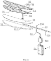
FIG. 4 is a schematic exploded view of the display module and the control module of the pedometer shoe according to an embodiment of the present disclosure. -
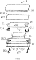
FIG. 5 is a schematic exploded view of the control module of the pedometer shoe according to an embodiment of the present disclosure. -
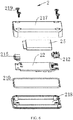
FIG. 6 is a schematic exploded view of the control module of the pedometer shoe viewed from another perspectives according to an embodiment of the present disclosure. -
FIG. 7 is a schematic structural diagram of a shoe sole of the pedometer shoe according to an embodiment of the present disclosure. - The technical solutions of embodiments of the present disclosure will be described clearly and completely in the following in combination with the accompanying drawings of the embodiments of the present disclosure. Obviously, the described embodiments are merely a part of embodiments of the present disclosure, but not all of the embodiments. All other embodiments obtained by those of ordinary skill in the art without creative efforts based on the embodiments of the present disclosure shall fall within the protection scope of the present disclosure.
- Referring to
FIGs. 1 to 4 , the embodiments of the present disclosure provide apedometer shoe 100, which includes a shoe body 1, acontrol module 2 and adisplay module 3. The shoe body 1 includes avamp 11 and ashoe sole 12 which are connected with each other. Thevamp 12 includes ashoe toe 13 corresponding to a toe position and a shoe upper 14 corresponding to a heel position. Thecontrol module 2 is arranged in theshoe sole 12 and sends out signals according to step counts. Thedisplay module 3 is attached to thevamp 11. Thedisplay module 3 includes adisplay area 30, and receives the signals and displays corresponding prompts. - In the embodiment, since the
control module 2 may send out signals according to the step counts, and thedisplay module 3 may receive the signals and display corresponding prompts, that is, thepedometer shoe 100 may count steps and display the step counts, so that a user can learn his or her real-time exercise amount in time. - It should be understood that, the prompts are displayed in the
display area 30. Preferably, since the shoe upper 14 has a large and flat surface, thedisplay module 3 may be attached to the shoe upper 14, so as to enhance the overall appearance of thepedometer shoe 100. - Further, as an alternative embodiment, the
display module 3 may display different colors according to different step counts. For example, thedisplay module 3 displays at least two colors. When the step count reaches 2500 steps, thedisplay area 30 presents red; when the step count reaches 5000 steps, thedisplay area 30 presents yellow; when the step count reaches 7500 steps, thedisplay area 30 presents green, etc. - In the embodiment, since the colors displayed in the
display area 30 are different, the user may intuitively determine the step count represented by the prompt, and the prompt is beautiful and diverse, which is beneficial to improve the user's experience of thepedometer shoe 100. - Further, as an alternative embodiment, the
display module 3 includes a plurality of thedisplay areas 30, and thedisplay areas 30 are lighted up one by one according to different step counts. For example, when the step count reaches 2500 steps, one of thedisplay areas 30 is lighted up; when the step count reaches 5000 steps, two of thedisplay areas 30 are lighted up; when the step count reaches 7500 steps, three of thedisplay areas 30 are lighted up; when the step count reaches 10000 steps, four of thedisplay areas 30 are lighted up, etc. - In the embodiment, since the numbers of the lighted up
display areas 30 are different, the user may intuitively know about the step count represented by the prompt, and the prompt is beautiful and diverse, which is beneficial to improve the user's experience of thepedometer shoe 100. - Further, as an alternative embodiment, heights of the plurality of
display areas 30 arranged from the shoe upper 14 toward theshoe toe 13 of thevamp 11 are gradually decreased. In other words, a direction along the shoe upper 14 toward theshoe toe 13 is defined as a first direction, and the heights of the plurality ofdisplay areas 30 arranged along the first direction are gradually decreased. Thedisplay areas 30 with gradually decreased heights may be configured to represent a range of steps in which the values are gradually decreased, to form an intuitive and obvious visual sense. - For example, the plurality of
display areas 30 include a first display area, a second display area, a third display area, and a fourth display area, which have sequentially increased heights. - When the step count reaches 2500 steps, the first display area is lighted up; when the step count reaches 5000 steps, the second display area is lighted up; when the step count reaches 7500 steps, the third display area is lighted up; and when the step count reaches 10000 steps, the fourth display area is lighted up.
- Alternatively, when the step count reaches 2500 steps, the first display area is lighted up; when the step count reaches 5000 steps, the first display area and the second display area are lighted up; when the step count reaches 7500 steps, the first display area, the second display area and the third display area are lighted up; and when the step count reaches 10000 steps, the first display area, the second display area, the third display area and the fourth display area are lighted up.
- In the embodiment, the increasing of the display height and/or the display number of the display areas enables the user to intuitively feel the increasing of the motion steps, which is beautiful and direct, and improves the user's experience.
- It should be understood that, the display pattern of the prompt displayed by the
display module 3 may be derived from a combination of the plurality ofdisplay areas 30, and obvious difference between a plurality of different display patterns formed by different combinations, enables the user to intuitively determine the step count represented by the display pattern. Moreover, the combined display patterns are beautiful and diverse, which is beneficial to improve the user's experience of thepedometer shoe 100. - The "different combinations" include, but are not limited to, different colors displayed by the
display area 30, different heights of thedisplay areas 30, different numbers of thedisplay areas 30 for display, different arrangements of thedisplay area 30 for display, or different combinations of the above means, etc. - Further, referring to
FIGs. 1 to 4 , as an alternative embodiment, thedisplay module 3 includes alight guide plate 31 and alight source 33. Thelight guide plate 31 includes alight exiting surface 311 and a reflecting surface which are opposite to each other, and a light incident surface connected between thelight exiting surface 311 and the reflecting surface. The reflecting surface is arranged facing an inside of the shoe body 1, and thelight exiting surface 311 is arranged facing an outside of the shoe body 1, so that light can exit from the shoe body 1, to realize the display function of thedisplay module 3. Thelight source 33 faces the light incident surface, and light emitted from thelight source 33 passes through the light incident surface and exits from the lightexiting surface 311. That is, the light emitted from thelight source 33 enters thelight guide plate 31 from the light incident surface, and exits from the lightexiting surface 311 and enters human eye after being reflected by the reflecting surface, to realize the display of thedisplay module 3. - Preferably, a plurality of the
light sources 33 are provided. Thelight sources 33 are arranged in one-to-one correspondence with the plurality ofdisplay areas 30, that is, eachdisplay area 30 corresponds to alight source 33. Since eachdisplay area 30 corresponds to alight source 33, the combinations of the plurality ofdisplay areas 30 can be controlled by controlling the states of the plurality oflight sources 33. The combination process is flexible and variable, so that the prompts of thedisplay module 3 can be rendered in a variety of different display patterns. - Further, as an alternative embodiment, the
light guide plate 31 is made of flexible material, so that thedisplay module 3 can be well attached to thevamp 11. Preferably, the reflecting surface of thelight guide plate 31 may be attached to thevamp 11 by heat pressing or bonding, such that the plurality ofdisplay areas 30 are erected, and the light exiting direction is toward the outside of the shoe body 1. - Further, referring to
FIGs. 1 to 4 , as an alternative embodiment, thedisplay module 3 further includes aflexible touch panel 35. Theflexible touch panel 35 generates a touch signal according to a touch operation, and thecontrol module 2 adjusts the prompt displayed by thedisplay module 3 according to the touch signal. - In the embodiment, since the
pedometer shoe 100 is integrated with theflexible touch panel 35, and theflexible touch panel 35 is capable of generating the touch signal according to the touch operation, and thecontrol module 2 adjusts the prompt displayed by thedisplay module 3 according to the touch signal. Therefore, thepedometer shoe 100 has a touch display function, and thepedometer shoe 100 is multifunctional. - Further, as an alternative embodiment, the
flexible touch panel 35 can generate the touch signal according to a long-pressing touch operation, and thecontrol module 2 adjusts the color of thedisplay module 3 according to the touch signal, that is, adjusts the display color of the prompt. - Further, as an alternative embodiment, the
flexible touch panel 35 generates the touch signal according to a sliding touch operation, and thecontrol module 2 adjusts brightness of thedisplay module 3 according to the touch signal, that is, adjusts the display the brightness of the prompt. The sliding operation includes, but is not limited to, sliding up and down, sliding left and right, or tilting sliding. - Further, as an alternative embodiment, the
flexible touch panel 35 generates the touch signal according to a double-click touch operation, and thecontrol module 2 turns on or off the prompt of thedisplay module 3 according to the touch signal. - Further, referring to
FIGs. 1 to 4 , as an alternative embodiment, theflexible touch panel 35 is attached to thelight exiting surface 311 of thelight guide plate 31. Theflexible touch panel 35 is made of flexible transparent material, and outputs the touch signal by sensing an external touch. - Further, referring to
FIGs. 1 to 4 , as an alternative embodiment, theflexible touch panel 35 includes atouch area 350 and a non-touch response area, thetouch area 350 is arranged opposite to thedisplay area 30, and the non-touch response area is located outside a range in which thetouch area 350 is located. Thetouch area 350 is capable of outputting the touch signal by sensing an external touch. - Preferably, the
flexible touch panel 35 is a single continuous flexible touch material with an entire surface can generate the touch signal in response to the touch operation. However, since theflexible touch panel 35 in the embodiment only needs to make a touch response at the position where thedisplay area 30 is located, and does not need to make any response at the connection positions among thedisplay areas 30, theflexible touch panel 35 thus form a plurality of non-touch response areas at the connection positions among thedisplay areas 30. Each non-touch response area is located between twoadjacent touch areas 350. Thetouch areas 350 are separated from each other by the non-touch response area. The non-touch response area can be made to not respond to touch operations by means of software masking. - Preferably, the
flexible touch panel 35 includes a plurality of thetouch areas 350 and a plurality of the non-touch response areas, and thetouch areas 350 and the non-touch response areas are alternately arranged. Such that, the plurality oftouch areas 350 are sequentially arranged at intervals, render in beautiful appearance, and respond to the touch operations accurately. - Further, referring to
FIGs. 1 to 4 , as an alternative embodiment, thedisplay module 3 further includes aprotective film 32 attached to theflexible touch panel 35. Theflexible touch panel 35 is sandwiched between theprotective film 32 and thelight guide plate 31. - Preferably, the
protective film 32 is attached to theflexible touch panel 35 by means of hot pressing or bonding. Theprotective film 32 covers theflexible touch panel 35 to protect theflexible touch panel 35. - Further, referring to
FIGs. 1 to 4 , as an alternative embodiment, theprotective film 32 includes thedisplay area 30 and an opaque area 301. The opaque area 301 is located outside a range in which thedisplay area 30 is located. Thedisplay area 30 is capable of displaying the prompt, and the opaque area 301 does not display anything. - Preferably, the
protective film 32 includes a plurality of thedisplay areas 30 and a plurality of the opaque areas 301, and the opaque areas 301 and thedisplay areas 30 are alternately arranged. Such that, the plurality ofdisplay areas 30 are sequentially arranged at intervals, so as to make the prompt beautiful and clear when displayed. - Further, referring to
FIGs. 1 to 4 , as an alternative embodiment, thedisplay module 3 further includes auniform light film 37 arranged between theflexible touch panel 35 and thelight exiting surface 311, theuniform light film 37 is configured to homogenize the light exiting from thelight guide plate 31. Theuniform light film 37 is made of flexible light transparent material. - Further, referring to
FIGs. 1 to 4 , as an alternative embodiment, thedisplay module 3 further includes a firstflexible circuit board 331, and thelight source 33 is mounted on the firstflexible circuit board 331. That is, the firstflexible circuit board 331 can be configured to hold up and be electrically connected to thelight source 33. The firstflexible circuit board 331 locates at the light incident surface side of thelight guide plate 31. Thelight source 33 can be a colored light emitting diode such as an RGB-LED. - Preferably, the first
flexible circuit board 331 is bent around the shoe upper 14 of thevamp 11. At this time, thewhole display module 3 is bent around the shoe upper 14 of thevamp 11. - Further, referring to
FIGs. 1 to 4 , as an alternative embodiment, the firstflexible circuit board 331 is electrically coupled to thecontrol module 2 through a secondflexible circuit board 34, and theflexible touch panel 35 is electrically coupled to thecontrol module 2 through a thirdflexible circuit 36. The secondflexible circuit board 34 and the thirdflexible circuit board 36 are freely bent according to the shape of thepedometer shoe 100. - Further, referring to
FIGs. 1 to 4 , as an alternative embodiment, thedisplay module 3 is bent around the shoe upper 14 of thevamp 11 and is attached to two opposite sides of thevamp 11, to facilitate the user to view the prompt from either side of the pedometer shoe 100 (either on the left or right side). - For example, the plurality of
display areas 30 include two display regions that are symmetrical, and the two display regions are respectively located at two sides of afirst center line 300. Each display region includes at least twodisplay areas 30, and the heights of the at least twodisplay areas 30 located in the same display region are sequentially increased along a direction. That is, in a same display region, at least two height-increasingdisplay areas 30 are included. Thedisplay areas 30 having different heights can be used to represent different ranges of steps, and the height-increasingdisplay areas 30 can be used to represent a range of steps in which the values are incremented to form an intuitive, apparent visual sense. - It should be understood that, the two display regions are not only symmetrical in shape, but the display patterns displayed are also symmetrical. Preferably, the heights of the
display areas 30 in the two display regions are increased in a direction toward each other. The height in the present embodiment refers to the length of thedisplay area 30 in a direction paralleled to thefirst center line 300. - The plurality of
light sources 33 are divided into two symmetrical light source groups which are respectively located at two sides of asecond center line 330. Each of the light source groups includes at least twolight sources 33, and the at least twolight sources 33 in a same light source group have different colors. Since thelight sources 33 are arranged in one-to-one correspondence with thedisplay area 30, at least twodisplay areas 30 having different display colors are included in each display region. Different display colors allow greater visibility of thedisplay module 3, and more combinations of display patterns are obtained, which also makes thepedometer shoe 100 more beautiful. - The shoe upper 14 of the
pedometer shoe 100 defines adorsal midline 10, and the two display regions of thedisplay module 3 are respectively located at two sides of thedorsal midline 10. At this time, thefirst center line 300 and thesecond center line 330 are both collinear with thedorsal midline 10, and the two light source groups are respectively located at two sides of thedorsal midline 10, to facilitate the user to view the motion steps from either side of the pedometer shoe 100 (either on the left or right side). - Further, referring to
FIGs. 1 to 7 , as an alternative embodiment, theshoe sole 12 is provided with arecess 121, and thecontrol module 2 is detachably received in therecess 121. Thecontrol module 2 includes asensor 23 and acontroller 24. Thesensor 23 is electrically coupled to thecontroller 24. Thesensor 23 collects user data and thecontroller 24 processes the collected user data. - In the embodiment, since the
control module 2 is detachably mounted to the shoe sole 12, when thepedometer shoe 100 needs to be cleaned, thecontrol module 2 can be detached, thereby effectively preventing thecontrol module 2 from water, and avoiding damage to components (such as thesensor 23 and the controller 24) integrated in thecontrol module 2, so that thepedometer shoe 100 has a long service life. At the same time, thedetached control module 2 can also be quickly charged and does not affect thepedometer shoe 100 as a shoe for daily use. Moreover, since thesensor 23 can collect user data, and thecontroller 24 can process the user data, so that thepedometer shoe 100 is multi-functionalized, and can meet diverse market demands. - Preferably, the user data includes but is not limited to step data, altitude data, speed data, acceleration data, foot temperature data, foot pressure data, walking distance data, and so on.
- Further, referring to
FIGs. 1 to 7 , as an alternative embodiment, theshoe sole 12 includes a top surface facing foot and a bottom surface facing the ground, and therecess 121 is defined on the top surface. - In the embodiment, since the
recess 121 is defined on the top surface, that is, thecontrol module 2 is mounted on the top surface of the shoe sole 12, thus, the shoe sole 12 can provide protection to thecontrol module 2 during the daily use of thepedometer shoe 100, without adding additional protection. - Further, as an alternative embodiment, the
control module 2 fits the inner wall of therecess 121 to prevent thecontrol module 2 from loosening, so that the components in thecontrol module 2 can also be prevented from being damaged by the collision during the movement of thepedometer shoe 100. - Preferably, the width of the
recess 121 is slightly less than that of thecontrol module 2 to allow thecontrol module 2 to fit the inner wall of therecess 121. - Preferably, the
recess 121 has an inverted trapezoidal shape so that thecontrol module 2 can be easily embedded into therecess 121. - Preferably, the top surface of the
shoe sole 12 is further provided with twodimples 122 which are respectively located at two sides of therecess 121, and both of the twodimples 122 communicate with therecess 121. The twodimples 122 can facilitate the user to hold thecontrol module 2 by hand, thereby reducing the difficulty of detaching thecontrol module 2. - Further, referring to
FIGs. 1 to 6 , as an alternative embodiment, thepedometer shoe 100 further includes aplug 213. Thedisplay module 3 is detachably plugged into thecontrol module 2 via theplug 213. - In the embodiment, since the
plug 213 is detachably plugged into thecontrol module 2, that is, the connection between thecontrol module 2 and thedisplay module 3 is detachable, therefore, the user can quickly connect or disconnect thecontrol module 2 with thedisplay module 3. - Further, as an alternative embodiment, the
plug 213 is fixed in the shoe sole 12, and when thecontrol module 2 is received in therecess 121, theplug 213 is plugged into thecontrol module 2 to electrically connect thecontrol module 2 to thedisplay module 3. When thecontrol module 2 is taken out from therecess 121, the power supply of thedisplay module 3 is cut off. - Further, as an alternative embodiment, the user data includes step data of the user, and the
controller 24 of thecontrol module 2 controls thedisplay module 3 to display a corresponding prompt according to the step data. At this time, thepedometer shoe 100 can count steps and display the step count, so that the user can learn his or her real-time exercise amount in time. - Further, referring to
FIGs. 1 to 4 , as an alternative embodiment, the firstflexible circuit board 331 is coupled to theplug 213 through the secondflexible circuit board 34. Both the firstflexible circuit board 331 and the secondflexible circuit board 34 can be freely bent according to the shape of thepedometer shoe 100. - Further, referring to
FIGs. 1 to 4 , as an alternative embodiment, the thirdflexible circuit board 36 is coupled to theflexible touch panel 35 and theplug 213. The thirdflexible circuit board 36 can be freely bent according to the shape of thepedometer shoe 100. - Further, as an alternative embodiment, the
plug 213 includes a signal conversion module, and the secondflexible circuit board 34 and the thirdflexible circuit board 36 are both connected to the signal conversion module. - Preferably, the signal conversion module converts a circuit board connection terminal (for example, a gold finger) into a USB connection terminal.
- Referring to
FIGs. 1 to 6 , further, as an alternative embodiment, thecontrol module 2 further includes ahousing 21, acircuit board 22, and abattery 25. Thecircuit board 22 is located in thehousing 21, and thecontroller 24 and thesensor 23 are both electrically connected to thecircuit board 22. Thebattery 25 is configured to supply power for thesensor 23, thecontroller 24, and thedisplay module 3. - For example, the
sensor 23 detects motion data and transmits a data signal to thecontroller 24 via thecircuit board 22. Thecontroller 24 receives and processes the data signal, and forms a control signal. The control signal is transmitted to thedisplay module 3 through thecircuit board 22, so that thedisplay module 3 displays a corresponding prompt. - Further, referring to
FIGs. 1 to 6 , as an alternative embodiment, thecontrol module 2 further includes afirst interface 212 mounted on thehousing 21, and thefirst interface 212 is electrically connected to thecircuit board 22. Theplug 213 is detachably plugged into thefirst interface 212. - In the embodiment, since the
plug 213 can be conveniently plugged into thefirst interface 212, and the connection between theplug 213 and thefirst interface 212 is detachable, therefore, the user can quickly connect or disconnect thecontrol module 2 with thedisplay module 3. - Preferably, the
first interface 212 is a waterproof interface for improving the waterproof performance of thecontrol module 2. - Further, referring to
FIGs. 1 to 6 , as an alternative embodiment, afirst communication hole 211 is defined on thehousing 21 for communicating with an inside and an outside of thehousing 21. Thefirst interface 212 is mounted to thefirst communication hole 211. - Further, referring to
FIGs. 1 to 6 , as an alternative embodiment, thecontrol module 2 further includes asecond interface 215 mounted on thehousing 21. When thecontrol module 2 is removed from therecess 121, thesecond interface 215 is connected to an external power source to charge thebattery 25. Of course, thesecond interface 215 can also connect thepedometer shoe 100 to other components for data transmission. - Further, referring to
FIGs. 1 to 6 , as an alternative embodiment, thefirst interface 212 and thesecond interface 215 are respectively located at opposite ends of thehousing 21. For example, a second communication hole opposite to thefirst communication hole 211 is defined on thehousing 21. The second communication hole is configured to communicate with the inside and the outside of thehousing 21. Thesecond interface 215 is mounted to the second communication hole. - Preferably, the
second interface 215 is a waterproof interface for improving the waterproof performance of thecontrol module 2. - Optionally, the
control module 2 further includes a Bluetooth component and/or a GPS component and/or a height sensor and/or a speed sensor, which are electrically connected to thecircuit board 22, so that thestep shoe 100 has more functions to meet diverse market demands. - Further, referring to
FIGs. 1 to 6 , as an alternative embodiment, thehousing 21 includes abottom frame 217 and atop cover 218. Thebottom frame 217 includes a bottom wall 2171 and aside wall 2172 connected to peripheries of the bottom wall 2171. A sealinggroove 2173 is defined on the top of theside wall 2172. The bottom edge of thetop cover 218 is provided with aflange 2181. Theflange 2181 is embedded into the sealinggroove 2173 for sealing thehousing 21. At the same time, thebottom frame 217 and thetop cover 218 can be locked by a plurality offasteners 219, so that thehousing 21 is sealed firmly. Thefasteners 219 include, but are not limited to, screws, rivets, and the like. - Preferably, the
housing 21 further includes awaterproof rubber ring 210 located in the sealinggroove 2173 for simultaneously abutting the bottom wall of the sealinggroove 2173 and the bottom wall of theflange 2181, to further improve the sealing performance of thehousing 21. - In the embodiment, the
first communication hole 211 and the second communication hole may be defined on two opposite side portions of theside wall 2172. - Preferably, the
sensor 23, thecontroller 24, thebattery 25, thecircuit board 22, thefirst interface 212, and thesecond interface 215 are all secured within thehousing 21. Therefore, all components inside thehousing 21 are not shaken with respect to thehousing 21 during the sway of thepedometer shoe 100, which can effectively prevent all components inside thehousing 21 from being injured. For example, thesensor 23 and thecontroller 24 are both fixed on thecircuit board 22, and thecircuit board 22, thefirst interface 212 and thesecond interface 215 can be fastened to the bottom wall 2171 by thefastener 219, and thebattery 25 is tightly held between thecircuit board 22 and the bottom wall 2171. Of course, thefirst interface 212 and thesecond interface 215 can also be tightly held between thecircuit board 22 and the bottom wall 2171. - The embodiments of the present disclosure have been described in detail above, and the principles and implementations of the present disclosure are described herein by using specific examples. The description of the above embodiments is merely for assisting in understand the method of the present disclosure and its core ideas. At the same time, for those skilled in the art, according to the idea of the present disclosure, there will be changes in the specific embodiments and application scopes. In conclusion, the content of the specification should not be construed as limiting the present disclosure.
Claims (20)
- A pedometer shoe comprising:a shoe body, comprising a vamp and a shoe sole which are connected with each other;a control module, arranged in the shoe sole and sending out signals according to step counts; anda display module attached to the vamp, the display module comprising a display area, and receiving the signals and displaying corresponding prompts.
- The pedometer shoe of claim 1, wherein the display module displays different colors according to different step counts.
- The pedometer shoe of claim 1, wherein the display module comprises a plurality of the display areas, and the display areas are lighted up one by one according to different step counts.
- The pedometer shoe of claim 3, wherein heights of the plurality of display areas arranged from a shoe upper toward a shoe toe of the vamp are gradually decreased.
- The pedometer shoe of any of claims 1 to 4, wherein the display module comprises:a light guide plate, comprising a light exiting surface and a reflecting surface which are opposite to each other, and a light incident surface connected between the light exiting surface and the reflecting surface, wherein the reflecting surface is attached to the vamp, to cause the light exiting surface facing an outside of the shoe body; anda light source facing the light incident surface, wherein light emitted from the light source passes through the light incident surface and exits from the light exiting surface.
- The pedometer shoe of claim 5, wherein the light guide plate is made of flexible material.
- The pedometer shoe of claim 5, wherein the display module further comprises a flexible touch panel, wherein the flexible touch panel generates a touch signal according to a touch operation, and the control module adjusts the prompt displayed by the display module according to the touch signal.
- The pedometer shoe of claim 7, wherein the flexible touch panel generates the touch signal according to a long-pressing touch operation, and the control module adjusts the color of the display module according to the touch signal.
- The pedometer shoe of claim 7, wherein the flexible touch panel generates the touch signal according to a sliding touch operation, and the control module adjusts brightness of the display module according to the touch signal.
- The pedometer shoe of claim 7, wherein the flexible touch panel is attached to the light exiting surface.
- The pedometer shoe of claim 7, wherein the flexible touch panel comprises a touch area and a non-touch response area, the touch area is arranged opposite to the display area, and the non-touch response area is located outside a range in which the touch area is located.
- The pedometer shoe of claim 11, wherein the flexible touch panel comprises a plurality of the touch areas and a plurality of the non-touch response areas, and the touch areas and the non-touch response areas are alternately arranged.
- The pedometer shoe of claim 7, wherein the display module further comprises a protective film attached to the flexible touch panel, the flexible touch panel being sandwiched between the protective film and the light guide plate.
- The pedometer shoe of claim 13, wherein the protective film comprises the display area and an opaque area, the opaque area being located outside a range in which the display area is located.
- The pedometer shoe of claim 14, wherein the protective film comprises a plurality of the display areas and a plurality of the opaque areas, and the opaque areas and the display areas are alternately arranged.
- The pedometer shoe of claim 7, wherein the display module further comprises a uniform light film arranged between the flexible touch panel and the light exiting surface.
- The pedometer shoe of claim 7, wherein the display module further comprises a first flexible circuit board, wherein the light source is mounted on the first flexible circuit board.
- The pedometer shoe of claim 17, wherein the first flexible circuit board is bent around a shoe upper of the vamp.
- The pedometer shoe of claim 17, wherein the first flexible circuit board is electrically coupled to the control module through a second flexible circuit board, and the flexible touch panel is electrically coupled to the control module through a third flexible circuit.
- The pedometer shoe of any of claims 1 to 4, wherein the display module is bent around a shoe upper of the vamp and is attached to two opposite sides of the vamp.
Applications Claiming Priority (1)
| Application Number | Priority Date | Filing Date | Title |
|---|---|---|---|
| PCT/CN2016/087843 WO2018000301A1 (en) | 2016-06-30 | 2016-06-30 | Pedometer shoe |
Publications (2)
| Publication Number | Publication Date |
|---|---|
| EP3479716A1 true EP3479716A1 (en) | 2019-05-08 |
| EP3479716A4 EP3479716A4 (en) | 2020-02-19 |
Family
ID=60545108
Family Applications (1)
| Application Number | Title | Priority Date | Filing Date |
|---|---|---|---|
| EP16906702.2A Withdrawn EP3479716A4 (en) | 2016-06-30 | 2016-06-30 | Pedometer shoe |
Country Status (4)
| Country | Link |
|---|---|
| US (1) | US20190310102A1 (en) |
| EP (1) | EP3479716A4 (en) |
| CN (1) | CN107466215A (en) |
| WO (1) | WO2018000301A1 (en) |
Family Cites Families (16)
| Publication number | Priority date | Publication date | Assignee | Title |
|---|---|---|---|---|
| US4402147A (en) * | 1981-05-27 | 1983-09-06 | Chyuan Jong Wu | Shoe having automatic step counter |
| US5640786A (en) * | 1995-07-05 | 1997-06-24 | Buyayez; Taher | Monitored footwear with step counter and speedometer display |
| KR200216691Y1 (en) * | 2000-10-10 | 2001-03-15 | 송문호 | Adhesion on foot counter device of shoes |
| US20070169381A1 (en) * | 2006-01-23 | 2007-07-26 | Gordon Steven N | Shoe Pedometer |
| TW200924661A (en) * | 2007-12-12 | 2009-06-16 | Jwo-Huei Jou | Wearable display module of organic light-emitting diode on shoes |
| US8769836B2 (en) * | 2010-06-22 | 2014-07-08 | Nike, Inc. | Article of footwear with color change portion and method of changing color |
| CN202819776U (en) * | 2012-03-21 | 2013-03-27 | 曾胜克 | automatic pedometer shoes |
| CN202653279U (en) * | 2012-03-28 | 2013-01-09 | 曾胜克 | Automatic step-counting shoes |
| CN202857982U (en) * | 2012-09-13 | 2013-04-10 | 安徽理工大学 | Intelligent step counting shoes |
| CN103960818A (en) * | 2013-01-30 | 2014-08-06 | 宁波大红鹰学院 | Lightweight fitness shoe capable of measuring heartbeat, step number and body weight in unit time |
| CN203274757U (en) * | 2013-06-13 | 2013-11-06 | 曾胜克 | Automatic pedometer and automatic pedometer shoes |
| US9781200B2 (en) * | 2013-07-01 | 2017-10-03 | Stepbuddies International | System, apparatus, and method for measuring number of user steps |
| TWM504486U (en) * | 2015-01-29 | 2015-07-11 | Taiwan Kangdexin Composite Material Co Ltd | Luminous shoes having pedometer function |
| CN105520257B (en) * | 2015-11-20 | 2018-12-25 | 纳智源科技(唐山)有限责任公司 | A kind of intelligent shoe |
| CN205162038U (en) * | 2015-11-25 | 2016-04-20 | 泉州奇鹭物联网科技有限公司 | Intelligence upset demonstration formula GPS location shoes |
| CN205306114U (en) * | 2016-01-18 | 2016-06-15 | 江苏工程职业技术学院 | A step -counting shoe |
-
2016
- 2016-06-30 US US16/307,894 patent/US20190310102A1/en not_active Abandoned
- 2016-06-30 EP EP16906702.2A patent/EP3479716A4/en not_active Withdrawn
- 2016-06-30 WO PCT/CN2016/087843 patent/WO2018000301A1/en not_active Ceased
- 2016-06-30 CN CN201680019625.XA patent/CN107466215A/en active Pending
Also Published As
| Publication number | Publication date |
|---|---|
| US20190310102A1 (en) | 2019-10-10 |
| EP3479716A4 (en) | 2020-02-19 |
| CN107466215A (en) | 2017-12-12 |
| WO2018000301A1 (en) | 2018-01-04 |
Similar Documents
| Publication | Publication Date | Title |
|---|---|---|
| EP3554418B1 (en) | Brushing device with illumination features | |
| US9226663B2 (en) | Systems and methods for optical isolation in measuring physiological parameters | |
| US10060788B2 (en) | Systems and methods for monitoring physiological parameters | |
| US10172529B2 (en) | Systems and methods for detecting physiological information of a user | |
| US10154814B2 (en) | Wearable personal information system | |
| US20140213917A1 (en) | Waterproof heart rate measuring apparatus | |
| AU2015341477B2 (en) | Systems and methods for optical isolation in measuring physiological parameters | |
| US20160041531A1 (en) | Biofeedback watches | |
| US9266006B2 (en) | Athletic pace signaling system and method | |
| US20200100345A1 (en) | System for displaying information on interactive illuminated apparel and accessories | |
| US20120029367A1 (en) | Heart rate waterproof measuring apparatus | |
| WO2018213542A1 (en) | Wearable bands with embedded circuitry | |
| EP4403093A1 (en) | Smart ring for measuring biometric signal | |
| US20180325234A1 (en) | Gel nail photocuring machine with multicolor light effects | |
| CN106659408A (en) | Biological information measuring device | |
| WO2018000302A1 (en) | Intelligent shoe | |
| EP3020331B1 (en) | Improving wrist device efficiency | |
| CN105831864A (en) | Luminous shoes with step counter | |
| US20190310102A1 (en) | Pedometer shoe | |
| EP3430932A1 (en) | Shoe and control method thereof | |
| CN209149100U (en) | A kind of 4G artificial intelligence wrist-watch | |
| CN220632054U (en) | Transmission type health detection ring | |
| CN213720238U (en) | Intelligent walking shoes for counting and entertainment teaching of infants | |
| US11202481B2 (en) | Illuminating device for sports helmet eye shield | |
| CN114205444A (en) | Lighting control device for eyesight protection |
Legal Events
| Date | Code | Title | Description |
|---|---|---|---|
| STAA | Information on the status of an ep patent application or granted ep patent |
Free format text: STATUS: THE INTERNATIONAL PUBLICATION HAS BEEN MADE |
|
| PUAI | Public reference made under article 153(3) epc to a published international application that has entered the european phase |
Free format text: ORIGINAL CODE: 0009012 |
|
| STAA | Information on the status of an ep patent application or granted ep patent |
Free format text: STATUS: REQUEST FOR EXAMINATION WAS MADE |
|
| 17P | Request for examination filed |
Effective date: 20181210 |
|
| AK | Designated contracting states |
Kind code of ref document: A1 Designated state(s): AL AT BE BG CH CY CZ DE DK EE ES FI FR GB GR HR HU IE IS IT LI LT LU LV MC MK MT NL NO PL PT RO RS SE SI SK SM TR |
|
| AX | Request for extension of the european patent |
Extension state: BA ME |
|
| DAV | Request for validation of the european patent (deleted) | ||
| DAX | Request for extension of the european patent (deleted) | ||
| STAA | Information on the status of an ep patent application or granted ep patent |
Free format text: STATUS: THE APPLICATION HAS BEEN WITHDRAWN |
|
| A4 | Supplementary search report drawn up and despatched |
Effective date: 20200117 |
|
| RIC1 | Information provided on ipc code assigned before grant |
Ipc: A43B 5/00 20060101AFI20200113BHEP Ipc: A43D 1/02 20060101ALI20200113BHEP Ipc: G01C 22/00 20060101ALI20200113BHEP Ipc: A43B 3/00 20060101ALI20200113BHEP |
|
| 18W | Application withdrawn |
Effective date: 20200205 |