EP3479136B1 - Method for estimating an average arrival date for a train of pulses - Google Patents
Method for estimating an average arrival date for a train of pulses Download PDFInfo
- Publication number
- EP3479136B1 EP3479136B1 EP17732478.7A EP17732478A EP3479136B1 EP 3479136 B1 EP3479136 B1 EP 3479136B1 EP 17732478 A EP17732478 A EP 17732478A EP 3479136 B1 EP3479136 B1 EP 3479136B1
- Authority
- EP
- European Patent Office
- Prior art keywords
- pulses
- pulse
- train
- arrival
- repetition period
- Prior art date
- Legal status (The legal status is an assumption and is not a legal conclusion. Google has not performed a legal analysis and makes no representation as to the accuracy of the status listed.)
- Active
Links
Images


Classifications
-
- G—PHYSICS
- G01—MEASURING; TESTING
- G01S—RADIO DIRECTION-FINDING; RADIO NAVIGATION; DETERMINING DISTANCE OR VELOCITY BY USE OF RADIO WAVES; LOCATING OR PRESENCE-DETECTING BY USE OF THE REFLECTION OR RERADIATION OF RADIO WAVES; ANALOGOUS ARRANGEMENTS USING OTHER WAVES
- G01S7/00—Details of systems according to groups G01S13/00, G01S15/00, G01S17/00
- G01S7/02—Details of systems according to groups G01S13/00, G01S15/00, G01S17/00 of systems according to group G01S13/00
- G01S7/021—Auxiliary means for detecting or identifying radar signals or the like, e.g. radar jamming signals
Definitions
- the present invention relates to a method for estimating an average arrival date on a radar detector of a pulse train emitted by a transmitter.
- the present invention also relates to an associated device for estimating an average arrival date on a radar detector of a pulse train.
- a radar detector is capable of receiving pulses from separate radar transmitters.
- Such a radar detector typically comprises a radar pulse receiver and a unit for processing the received pulses.
- the function of the receiver is to receive, detect and characterize the pulses from radar transmitters. The pulses being received at the rate of their transmission, the receiver is capable of producing successive characterizations corresponding to the different radar pulses in the order of their reception.
- the function of the processing unit is to sort the received pulses according to a consistency criterion in order to construct sets of pulses representative of the original radar transmitters.
- such sorting is likely to create characterized pulse trains which do not correspond to the pulse trains actually emitted by each of the radar transmitters. For example, pulses from a pulse train are likely to be missing compared to the pulse train actually emitted or to come from another radar transmitter.
- pulses are also likely to be missed due to the limited sensitivity of the radar detector or even an interruption in the reception of radar signals.
- the limits of sensitivity of the radar detector are, for example, due to a too weak power signal, to the non-illumination of the radar detector, or even also to radio propagation phenomena of the carrier platform of the radar detector .
- the document US 5,583,505 A describes an example of a radar pulse detection and classification system.
- the document US 2005/033789 A describes a multiple correlation device configured to estimate a pulse repetition period associated with a received pulse train .
- the document EP 2,309,289 A describes a method for separating a train of nested radar pulses.
- the invention is preferably integrated into a radar detector, more precisely into the part previously called the processing unit.
- a transmitter 8, a radar detector 9 and a device 10 for estimating an average arrival date of a train of pulses received by the radar detector 9 are illustrated by the figure 1 .
- the transmitter 8 is arranged on a carrier platform, for example, an aircraft, a drone, a ship, a land vehicle or a land station.
- the transmitter 8 is configured to transmit pulse trains.
- the transmitter 8 is, for example, a transmitter of radar signals.
- the radar detector 9 is arranged on a carrier platform separate from the carrier platform of the transmitter 8.
- the carrier platform of the radar detector 9 is, for example, an aircraft, a drone, a ship, a land vehicle or a land station.
- the radar detector 9 is configured to receive pulse trains, in particular from the transmitter 8.
- the radar detector 9 comprises a pulse receiver arriving at the radar detector 9 and a unit for processing said pulses.
- the function of the radar detector receiver 9 is to receive, detect and characterize the pulses coming from radar transmitters.
- the function of the radar detector receiver 9 is to measure the arrival dates of the pulses from the pulse trains sent by the transmitter 8 and arriving at the radar detector 9.
- the processing unit of the radar detector 9 has the function of sorting, according to a consistency criterion, the pulses received in order to construct sets of pulses representative of the original radar transmitters.
- the radar detector 9 is, for example, a radar signal detector.
- the speed camera detector 9 is connected to the device 10 which is, for example, placed on the same platform as the speed camera detector 9.
- the device 10 is a processing unit connected to the processing unit of the radar detector 9. As such, the device 10 is, for example, a dedicated processor.
- the device 10 is integrated into the processing system of the radar detector 9.
- the processor of the device 10 includes a data processing unit, memories and an information carrier reader.
- the processor of the device 10 is capable of interacting with a computer program product comprising a readable medium of information readable by the processor, usually by the data processing unit of the processor. On the readable information carrier is stored a computer program comprising program instructions.
- the computer program is loadable on the data processing unit of the processor and is adapted to entail the implementation of a method for estimating an average arrival date of a train of pulses received by the speed camera detector 9.
- n denotes the n-th pulse of a train of pulses.
- the estimation method comprises a step 100 of supplying, by the radar detector 9, to the device 10, the arrival dates t n on the radar detector 9 of the pulses of the train of pulses transmitted by the transmitter. 8.
- arrival dates t n have, for example, been measured by the receiver of the radar detector 9.
- the supplying step 100 also comprises the supply by the radar detector 9, to the device 10, of an estimate of the repetition period of the pulses T emitted by the transmitter 8.
- the repetition period of the pulses T is , for example, estimated by the processing unit of the radar detector 9. Such a repetition period of the pulses T corresponds to the duration separating two consecutive pulses emitted by the transmitter 8.
- the repetition period of the pulses T is, for example, from a database following the identification of the transmitter 8.
- the repetition period of the pulses supplied T is likely to be affected by an estimation error.
- the estimation error over the pulse repetition period is, for example, due to the Doppler effect, especially when the variation in the relative distance between the transmitter and the radar detector no longer becomes negligible during the listening time. Such a situation is found, for example, in the case of on-board radar detectors operating at high speed.
- the estimation error is likely to be due to a value of pulse repetition period of a database which does not correspond exactly to that of the radar being listened to.
- the estimation error is assumed to be small compared to the value of the pulse repetition period. For example, if the pulse repetition period is on the order of a millisecond, the estimation error is assumed to be on the order of a microsecond.
- the estimation method comprises a step 120 of determining, for each pulse of the train of pulses received, the remainder y n of the Euclidean division of the arrival date t n , shifted by the value of ⁇ previously chosen, by the repetition period of the pulses T.
- the arrival date values t n are taken from measurements made by the radar detector 9 and, as such, the arrival date values t n are, in fact, equal to a true value t v, n added to a measurement error w n .
- the repetition period of the pulses T is determined from the arrival dates t n estimated by the radar detector 9, which means that the repetition period of the pulses T is equal to a true value T v added to an estimation error ⁇ T.
- the remainder y n corresponds to the arrival date on which the corresponding pulse should have arrived on the radar detector 9, to a measurement error w n and to an error of estimation ⁇ T over the period of repetition of pulses.
- Such an adjusted curve is obtained by linear regression from the two series of values previously calculated: the remainders y n and the numbers x n .
- the regression line is, for example, obtained by the method of least squares.
- the estimated average arrival date is equal to the sum of the ordinate at the origin of the adjusted curve and the previously calculated offset. Such an adjustment is comparable to an average of the residuals y n determined for each pulse.
- the estimation error is equal to the opposite of the directing coefficient or slope of the line of regression.
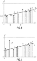
- the abscissa axis corresponds to the numbers x n of the pulses and the ordinate axis corresponds to the remainders y n of the pulses.
- the values of the residues y n of each pulse as a function of the numbers x n of each pulse are represented by dots in bold. Pulse numbers x n at the braces M do not include associated residues y n , due to a lack of pulses.
- Line C is the curve obtained at the end of the adjustment.
- the value ( t 0 - ⁇ ) is the ordinate at the origin of the straight line C, which therefore allows an estimate of the average arrival date.
- the value - ⁇ T is the directing coefficient of the line C, which is therefore the opposite of the error of estimation of the repetition period of the pulses T supplied.
- the value .w n indicates the measurement error w n on the dates of arrival of the pulses.
- the estimation method comprises a step 140 of calculating, for each pulse, an adjustment residue in order to eliminate outliers from the residues y n .
- the adjustment residue of each pulse is obtained as a function of the remainder y n determined for the pulse and of the corresponding remainder obtained by the adjustment.
- an adjustment residue is calculated equal to the absolute value of the ratio of the difference between the remainder y n and the value y ( x n ) of the regression line for the number x n considered by the standard deviation ⁇ t of the measurement error w n on the arrival dates.
- the value of y n is considered to be outliers and the corresponding pair ( x n , y n ), formed by a number x n and the associated y n remainder is eliminated.
- the predetermined threshold A is, for example, equal to three. An example of an outlier is illustrated on the figure 4 with the reference "VA".
- a predetermined number B of consecutive values of y n are outliers, this means that there is a change in pulse repetition period and, consequently, that the measurement of pulse repetition period T supplied is not representative of reality.
- the predetermined number B is, for example, equal to three.
- the estimation method comprises repeating: the determining step 130 on the basis of the numbers x n and of the residues y n remaining after the preceding step 140 of analysis and elimination; as well as from step 140 until the outliers are completely eliminated, that is to say until the calculated residues are strictly below the predetermined threshold A.
- the values of the average arrival date of the pulse train and of the error made over the pulse repetition period are respectively based on the last values of ordinate at the origin b and of directing coefficient a of the regression line, such values being calculated according to formulas (11) and (12).
- the given value D is, for example, equal to ten.
- a simplified variant repeats step 130 only once by providing second values of ordinate at the origin b and of directing coefficient a of the regression line, for determine the values of the average arrival date of the pulse train and of the error made over the pulse repetition period still according to the formulas (11) and (12).
- the figure 5 illustrates an example of variation of the repetition period of the pulses T of a transmitter.
- This figure shows zones Z1 and Z3 corresponding to pulses for which the estimation error over the repetition period of the pulses T is small and zones Z2 and Z4 correspond to pulses for which the estimation error over the pulse repetition period T is high.
- the adjustment residues relating to the pulses of the zones Z2 and Z4 have high values, similarly to outliers.
- the representation of the residues y n as a function of the numbers x n makes it possible to highlight such significant changes in the repetition period of the pulses T and to deduce therefrom switching patterns for the repetition period of the pulses T.
- the brace G denotes an example of a switching pattern. Recognition of the switching patterns helps to identify the mode and type of transmitter observed.
- the method is particularly robust as well to the lack of pulses received, as to imprecisions on the period of repetition of the pulses supplied or to outliers likely to be caused, for example, by defects in upstream processing, multiple reflections, material defects, or even by changes in the repetition period T of the pulses.
- the method makes it possible to precisely estimate an average arrival date of a train of pulses received by the radar detector 9.
- the concept of average arrival date makes it possible to provide a single consolidated value for a train of pulses, instead of a set of values.
- the data rate exchanged between the radar detector 9 and a central device whose function is to estimate the location of the transmitters of radar signals from differences in arrival dates, is reduced.
- the average arrival dates estimated for the pulse trains received by the radar detector 9 are particularly suitable for being transmitted and used for the purpose of locating the transmitter 8 by a difference in arrival date method. .
- no offset ⁇ is used to calculate the numbers ( x n ) and the remainders ( y n ), which is equivalent to taking the offset ⁇ as always zero in the previous formulas and embodiments.
- the introduction of a nonzero offset ⁇ in the previous embodiments makes it possible to work on staggered arrival dates corresponding to smaller numbers, therefore easier to use.
Description
La présente invention concerne un procédé d'estimation d'une date d'arrivée moyenne sur un détecteur de radars d'un train d'impulsions émis par un émetteur. La présente invention se rapporte, également, à un dispositif associé d'estimation d'une date d'arrivée moyenne sur un détecteur de radars d'un train d'impulsions.The present invention relates to a method for estimating an average arrival date on a radar detector of a pulse train emitted by a transmitter. The present invention also relates to an associated device for estimating an average arrival date on a radar detector of a pulse train.
Un détecteur de radars est propre à recevoir des impulsions en provenance d'émetteurs radar distincts. Un tel détecteur de radars comprend typiquement un récepteur d'impulsions radar et une unité de traitement des impulsions reçues. Le récepteur a pour fonction de recevoir, de détecter et de caractériser les impulsions en provenance d'émetteurs radars. Les impulsions étant reçues au rythme de leur émission, le récepteur est propre à produire des caractérisations successives correspondant aux différentes impulsions radar dans l'ordre de leur réception. L'unité de traitement a pour fonction de trier selon un critère de cohérence les impulsions reçues pour construire des ensembles d'impulsions représentatifs des émetteurs radar d'origine.A radar detector is capable of receiving pulses from separate radar transmitters. Such a radar detector typically comprises a radar pulse receiver and a unit for processing the received pulses. The function of the receiver is to receive, detect and characterize the pulses from radar transmitters. The pulses being received at the rate of their transmission, the receiver is capable of producing successive characterizations corresponding to the different radar pulses in the order of their reception. The function of the processing unit is to sort the received pulses according to a consistency criterion in order to construct sets of pulses representative of the original radar transmitters.
Cependant, le tri effectué par une telle unité de traitement est limité lorsque les caractéristiques des différents émetteurs radar sont proches les unes des autres.However, the sorting carried out by such a processing unit is limited when the characteristics of the different radar transmitters are close to each other.
En outre, un tel tri est susceptible de créer des trains d'impulsions caractérisés ne correspondant pas aux trains d'impulsions réellement émis par chacun des émetteurs radars. Par exemple, des impulsions d'un train d'impulsions sont susceptibles d'être manquantes par rapport au train d'impulsions réellement émis ou encore de provenir d'un autre émetteur radar.In addition, such sorting is likely to create characterized pulse trains which do not correspond to the pulse trains actually emitted by each of the radar transmitters. For example, pulses from a pulse train are likely to be missing compared to the pulse train actually emitted or to come from another radar transmitter.
De plus, des impulsions sont aussi susceptibles de manquer du fait de la sensibilité limitée du détecteur de radars ou encore d'interruption dans la réception des signaux radars. Les limites de sensibilité du détecteur de radars sont, par exemple, dues à un signal de puissance trop faible, à la non-illumination du détecteur de radars, voire également à des phénomènes de propagation hertzienne de la plate-forme porteuse du détecteur de radars.In addition, pulses are also likely to be missed due to the limited sensitivity of the radar detector or even an interruption in the reception of radar signals. The limits of sensitivity of the radar detector are, for example, due to a too weak power signal, to the non-illumination of the radar detector, or even also to radio propagation phenomena of the carrier platform of the radar detector .
En outre, afin de localiser les émetteurs radar, notamment à partir de méthodes basées sur la différence de dates d'arrivée (en anglais Time Différence Of Arrival) plusieurs détecteurs de radars sont mis en réseau. Les dates d'arrivée des trains d'impulsions reçus par de tels détecteurs de radars sont, ensuite, transmises à un dispositif central dont la fonction est de localiser les émetteurs radar à partir des dates d'arrivée transmises.In addition, in order to locate the radar transmitters, in particular from methods based on the difference in arrival dates (in English Time Difference Of Arrival ) several radar detectors are networked. The arrival dates of the pulse trains received by such radar detectors are then transmitted to a central device whose function is to locate the radar transmitters from the arrival dates transmitted.
Néanmoins, de telles transmissions exigent un débit relativement élevé au regard des liaisons de données normalisées existantes.However, such transmissions require a relatively high speed compared to existing standardized data links.
Le document
Il existe donc un besoin pour un procédé permettant d'estimer précisément les dates d'arrivée de trains d'impulsions reçus par un détecteur de radars tout en permettant une transmission des dates d'arrivées estimées avec un débit adapté aux liaisons de données normalisées existantes.There is therefore a need for a method making it possible to precisely estimate the arrival dates of pulse trains received by a radar detector while allowing transmission of the estimated arrival dates with a bit rate adapted to existing standardized data links. .
A cet effet, l'invention a pour objet un procédé d'estimation d'une date d'arrivée moyenne sur un détecteur de radars, d'un train d'impulsions émis par un émetteur, le détecteur de radars fournissant une date d'arrivée pour chaque impulsion du train d'impulsions et une période de répétition des impulsions du train d'impulsions, le procédé comprenant les étapes de :
- détermination, pour chaque impulsion du train d'impulsions, du reste de la division euclidienne de la date d'arrivée de l'impulsion par la période de répétition des impulsions, et
- estimation d'une date d'arrivée moyenne du train d'impulsions à partir d'une moyenne des restes déterminés pour chaque impulsion.
- determination, for each pulse of the pulse train, of the remainder of the Euclidean division of the date of arrival of the pulse by the period of repetition of the pulses, and
- estimation of an average arrival date of the pulse train from an average of the residues determined for each pulse.
L'invention s'intègre, de préférence, à un détecteur de radars, plus précisément à la partie appelée précédemment unité de traitement.The invention is preferably integrated into a radar detector, more precisely into the part previously called the processing unit.
Suivant des modes de mise en oeuvre particuliers, le procédé d'estimation comprend une ou plusieurs des caractéristiques suivantes, prises isolément ou suivant toutes les combinaisons techniquement possibles :
- l'étape d'estimation comprend l'association d'un numéro à chaque impulsion du train d'impulsions, le numéro de chaque impulsion étant obtenu par division de la date d'arrivée de l'impulsion par la période de répétition des impulsions, l'étape d'estimation comprenant, en outre, la détermination d'une droite de régression à partir de couples formés par les numéros des impulsions et les restes déterminés pour les impulsions, la date d'arrivée moyenne estimée étant fonction de l'ordonnée à l'origine de la droite de régression.
- pour chaque impulsion du train d'impulsions, le numéro et le reste sont calculés à partir de la date d'arrivée de l'impulsion diminuée d'un décalage, le décalage étant choisi de sorte que la différence entre la date d'arrivée de la première impulsion du train et le décalage soit comprise au sens large entre zéro et la période de répétition des impulsions.
- la droite de régression est obtenue par la méthode des moindres carrés ordinaires.
- la période de répétition des impulsions est affectée d'une erreur d'estimation, ladite erreur d'estimation étant égale à l'opposé de la pente de la droite de régression.
- les dates d'arrivée des impulsions sont affectées d'une erreur de mesure, l'étape d'estimation comprenant le calcul, pour chaque impulsion du train, d'un résidu égal à la valeur absolue de la différence entre le reste et la valeur donnée par la droite de régression pour le numéro correspondant au reste considéré, divisée par l'écart-type de l'erreur de mesure sur les dates d'arrivée, l'étape d'estimation comprenant, en outre, l'élimination des impulsions dont le résidu est supérieur ou égal à un seuil prédéterminé et la répétition de la sous-étape de détermination d'une droite de régression à partir des impulsions restantes.
- le seuil prédéterminé est égal à trois.
- le procédé comprend la répétition des sous-étapes de détermination de la droite de régression, de calcul d'un résidu et d'élimination d'impulsions jusqu'à ce que les résidus calculés soient strictement inférieurs au seuil prédéterminé.
- lorsque des résidus sont supérieurs ou égaux au seuil prédéterminé et correspondent à au moins trois numéros d'impulsions consécutifs, la période de répétition des impulsions est considérée avoir des changements de valeurs.
- the estimation step comprises associating a number with each pulse of the pulse train, the number of each pulse being obtained by dividing the arrival date of the pulse by the pulse repetition period, the estimation step further comprising the determination of a regression line from couples formed by the numbers of the pulses and the residues determined for the pulses, the estimated average arrival date being a function of the ordinate at the origin of the regression line.
- for each pulse in the pulse train, the number and the rest are calculated from the arrival date of the pulse minus an offset, the offset being chosen so that the difference between the arrival date of the first train pulse and the offset is broadly between zero and the pulse repetition period.
- the regression line is obtained by the ordinary least squares method.
- the pulse repetition period is affected by an estimation error, said estimation error being equal to the opposite of the slope of the regression line.
- the arrival dates of the pulses are affected by a measurement error, the estimation step comprising the calculation, for each pulse of the train, of a residue equal to the absolute value of the difference between the remainder and the value given by the regression line for the number corresponding to the remainder considered, divided by the standard deviation of the measurement error on the arrival dates, the estimation step further comprising eliminating the pulses whose residue is greater than or equal to a predetermined threshold and the repetition of the sub-step of determining a regression line from the remaining pulses.
- the predetermined threshold is equal to three.
- the method comprises repeating the sub-steps of determining the regression line, calculating a residue and eliminating pulses until the calculated residues are strictly below the predetermined threshold.
- when residues are greater than or equal to the predetermined threshold and correspond to at least three consecutive pulse numbers, the period of repetition of the pulses is considered to have changes in values.
L'invention concerne aussi un dispositif d'estimation d'une date d'arrivée moyenne sur un détecteur de radars d'un train d'impulsions émis par un émetteur, le dispositif comprenant un processeur configuré pour :
- recevoir une date d'arrivée de chaque impulsion du train d'impulsion et une période de répétition des impulsions dudit train d'impulsions, en provenance du détecteur de radars,
- déterminer, pour chaque impulsion du train d'impulsions, le reste de la division euclidienne de la date d'arrivée de l'impulsion par la période de répétition des impulsions, et
- estimer une date d'arrivée moyenne du train d'impulsions à partir d'une moyenne des restes déterminés pour chaque impulsion.
- receive a date of arrival of each pulse of the pulse train and a period of repetition of the pulses of said pulse train, coming from the radar detector,
- determine, for each pulse in the pulse train, the remainder of the Euclidean division of the date of arrival of the pulse by the pulse repetition period, and
- estimate an average date of arrival of the pulse train from an average of the residues determined for each pulse.
D'autres caractéristiques et avantages de l'invention apparaîtront à la lecture de la description qui suit de modes de réalisation de l'invention, donnée à titre d'exemple uniquement et en référence aux dessins qui sont :
-
figure 1 , une vue schématique d'un exemple d'un émetteur, d'un détecteur de radars et d'un dispositif d'estimation d'une date d'arrivée moyenne d'un train d'impulsions reçu par le détecteur de radars, -
figure 2 , un exemple d'un organigramme des étapes d'un procédé d'estimation d'une date d'arrivée moyenne d'un train d'impulsions reçu par un détecteur de radars, -
figure 3 , un premier exemple d'une représentation des restes déterminés pour chaque impulsion en fonction des numéros de chaque impulsion, la représentation comprenant des zones où des impulsions sont manquantes, -
figure 4 , un deuxième exemple d'une représentation des restes déterminés pour chaque impulsion en fonction des numéros de chaque impulsion, la représentation comportant une valeur aberrante, et -
figure 5 , un troisième exemple d'une représentation des restes déterminés pour chaque impulsion en fonction des numéros de chaque impulsion, la période de répétition des impulsions variant au cours du temps.
-
figure 1 , a schematic view of an example of a transmitter, a radar detector and a device for estimating an average date of arrival of a train of pulses received by the radar detector, -
figure 2 , an example of a flow diagram of the steps of a method for estimating an average arrival date of a train of pulses received by a radar detector, -
figure 3 , a first example of a representation of the residues determined for each pulse as a function of the numbers of each pulse, the representation comprising zones where pulses are missing, -
figure 4 , a second example of a representation of the residues determined for each pulse as a function of the numbers of each pulse, the representation comprising an outlier, and -
figure 5 , a third example of a representation of the residues determined for each pulse as a function of the numbers of each pulse, the repetition period of the pulses varying over time.
Un émetteur 8, un détecteur de radars 9 et un dispositif 10 d'estimation d'une date d'arrivée moyenne d'un train d'impulsions reçu par le détecteur de radars 9 sont illustrés par la
L'émetteur 8 est disposé sur une plate-forme porteuse, par exemple, un aéronef, un drone, un navire, un véhicule terrestre ou une station terrestre.The
L'émetteur 8 est configuré pour émettre des trains d'impulsions.The
L'émetteur 8 est, par exemple, un émetteur de signaux radar.The
Le détecteur de radars 9 est disposé sur une plate-forme porteuse distincte de la plate-forme porteuse de l'émetteur 8. La plate-forme porteuse du détecteur de radars 9 est, par exemple, un aéronef, un drone, un navire, un véhicule terrestre ou une station terrestre.The
Le détecteur de radars 9 est configuré pour recevoir des trains d'impulsions, notamment en provenance de l'émetteur 8.The
Le détecteur de radars 9 comprend un récepteur d'impulsions arrivant sur le détecteur de radars 9 et une unité de traitement desdites impulsions.The
Le récepteur du détecteur de radars 9 a pour fonction de recevoir, de détecter et de caractériser les impulsions en provenance d'émetteurs radar. En particulier, le récepteur du détecteur de radars 9 a pour fonction de mesurer les dates d'arrivée des impulsions des trains d'impulsions émis par l'émetteur 8 et arrivant sur le détecteur de radars 9.The function of the
L'unité de traitement du détecteur de radars 9 a pour fonction de trier selon un critère de cohérence les impulsions reçues pour construire des ensembles d'impulsions représentatifs des émetteurs radar d'origine.The processing unit of the
Le détecteur de radars 9 est, par exemple, un détecteur de signaux radar.The
Le détecteur de radars 9 est en liaison avec le dispositif 10 qui est, par exemple, disposé sur la même plate-forme que le détecteur de radars 9.The
Le dispositif 10 est un ensemble de traitement connexe à l'unité de traitement du détecteur de radars 9. À ce titre, le dispositif 10 est, par exemple, un processeur dédié.The
En variante, le dispositif 10 est intégré dans le système de traitement du détecteur de radars 9.As a variant, the
Le processeur du dispositif 10 comprend une unité de traitement de données, des mémoires et un lecteur de support d'informations.The processor of the
Le processeur du dispositif 10 est propre à interagir avec un produit programme d'ordinateur comprenant un support lisible d'informations lisible par le processeur, usuellement par l'unité de traitement de données du processeur. Sur le support lisible d'information est mémorisé un programme d'ordinateur comprenant des instructions de programme.The processor of the
Le programme d'ordinateur est chargeable sur l'unité de traitement de données du processeur et est adapté pour entraîner la mise en oeuvre d'un procédé d'estimation d'une date d'arrivée moyenne d'un train d'impulsions reçu par le détecteur de radars 9.The computer program is loadable on the data processing unit of the processor and is adapted to entail the implementation of a method for estimating an average arrival date of a train of pulses received by the
Un exemple de mise en oeuvre d'un procédé d'estimation utilisant le dispositif 10 est maintenant décrit en référence à la
Dans toute la suite de la description, l'indice n désigne la n-ième impulsion d'un train d'impulsions.In the remainder of the description, the index n denotes the n-th pulse of a train of pulses.
Initialement, le procédé d'estimation comprend une étape 100 de fourniture, par le détecteur de radars 9, au dispositif 10, des dates d'arrivée tn sur le détecteur de radars 9 des impulsions du train d'impulsions émis par l'émetteur 8. De telles dates d'arrivée tn ont été, par exemple, mesurées par le récepteur du détecteur de radars 9.Initially, the estimation method comprises a
L'étape de fourniture 100 comprend, également, la fourniture par le détecteur de radars 9, au dispositif 10, d'une estimation de la période de répétition des impulsions T émises par l'émetteur 8. La période de répétition des impulsions T est, par exemple, estimée par l'unité de traitement du détecteur de radars 9. Une telle période de répétition des impulsions T correspond à la durée séparant deux impulsions consécutives émises par l'émetteur 8.The supplying
Dans une variante, la période de répétition des impulsions T est, par exemple, issue d'une base de données suite à l'identification de l'émetteur 8.In a variant, the repetition period of the pulses T is, for example, from a database following the identification of the
La période de répétition des impulsions fournie T est susceptible d'être affectée d'une erreur d'estimation. L'erreur d'estimation sur la période de répétition des impulsions est, par exemple, due à l'effet Doppler, notamment lorsque la variation de la distance relative entre l'émetteur et le détecteur de radars ne devient plus négligeable durant la durée d'écoute. Une telle situation se retrouve, par exemple, dans le cas de détecteurs de radars embarqués évoluant à grande vitesse. L'erreur d'estimation est susceptible d'être due à une valeur de période de répétition des impulsions d'une base de données qui ne correspond pas exactement à celle du radar écouté.The repetition period of the pulses supplied T is likely to be affected by an estimation error. The estimation error over the pulse repetition period is, for example, due to the Doppler effect, especially when the variation in the relative distance between the transmitter and the radar detector no longer becomes negligible during the listening time. Such a situation is found, for example, in the case of on-board radar detectors operating at high speed. The estimation error is likely to be due to a value of pulse repetition period of a database which does not correspond exactly to that of the radar being listened to.
L'erreur d'estimation est supposée faible devant la valeur de la période de répétition des impulsions. Par exemple, si la période de répétition des impulsions est de l'ordre de la milliseconde, l'erreur d'estimation est supposée être de l'ordre de la microseconde.The estimation error is assumed to be small compared to the value of the pulse repetition period. For example, if the pulse repetition period is on the order of a millisecond, the estimation error is assumed to be on the order of a microsecond.
Le procédé d'estimation comprend une étape 110 de détermination d'un numéro xn pour chaque impulsion du train d'impulsions reçu par le détecteur de radars 9, dont la date d'arrivée est tn. Avantageusement, le numéro xn de chaque impulsion est égal à la partie entière de la division de la différence entre la date d'arrivée tn de l'impulsion et un décalage, par la période de répétition des impulsions T fournie ; ce qui est résumé par l'expression suivante : ![]()
- T est la période de répétition des impulsions,
- Δ est un décalage choisi de façon que la date d'arrivée de la première impulsion du train et le décalage soit compris au sens large entre zéro et la période de répétition T, et
- └X┘ est la partie entière de X.
- T is the repetition period of the pulses,
- Δ is an offset chosen so that the date of arrival of the first train pulse and the offset are understood in the broad sense between zero and the repetition period T, and
- └ X ┘ is the integer part of X.
Le procédé d'estimation comprend une étape 120 de détermination, pour chaque impulsion du train d'impulsions reçu, du reste yn de la division euclidienne de la date d'arrivée tn, décalée de la valeur de Δ précédemment choisie, par la période de répétition des impulsions T. Un tel reste yn s'exprime de la façon suivante : ![]()
![]()
Les valeurs de date d'arrivée tn sont issues de mesures effectuées par le détecteur de radars 9 et, à ce titre, les valeurs de date d'arrivée tn sont, en fait, égales à une valeur vraie tv,n additionnée à une erreur de mesure wn. De la même façon, la période de répétition des impulsions T est déterminée à partir des dates d'arrivée tn estimées par le détecteur de radars 9, ce qui signifie que la période de répétition des impulsions T vaut une valeur vraie Tv additionnée à une erreur d'estimation εT .The arrival date values t n are taken from measurements made by the
Ainsi, le reste yn correspond à la date d'arrivée à laquelle l'impulsion correspondante aurait dû arriver sur le détecteur de radars 9, à une erreur de mesure wn près et à une erreur d'estimation εT sur la période de répétition des impulsions près.Thus, the remainder y n corresponds to the arrival date on which the corresponding pulse should have arrived on the
Le reste yn s'exprime également de la façon suivante : 
On remarquera que (tv,n - xn · Tv ) correspond à une date unique ne dépendant pas de n puisqu'on retranche de la date d'arrivée vraie courante le nombre courant de périodes de répétition des impulsions vraie. Cette date unique est prise comme date d'arrivée initiale du train d'impulsion et est notée t 0. Ainsi, le reste yn s'exprime, également, de la façon suivante : ![]()
![]()
Cela signifie que les valeurs des restes yn sont distribuées autour d'une droite de régression qui a pour équation : ![]()
![]()
![]()
![]()
![]()
![]()
Le procédé d'estimation comprend une étape 130 d'ajustement d'une courbe aux restes yn de chaque impulsion en fonction des numéros xn de chaque impulsion pour obtenir une courbe ajustée, aussi appelée « droite de régression » d'équation y = ax + b. The estimation method comprises a
Une telle courbe ajustée est obtenue par régression linéaire à partir des deux séries de valeurs précédemment calculées : les restes yn et les numéros xn. La droite de régression est, par exemple, obtenue par la méthode des moindres carrés.Such an adjusted curve is obtained by linear regression from the two series of values previously calculated: the remainders y n and the numbers x n . The regression line is, for example, obtained by the method of least squares.
Une telle droite de régression d'équation y = ax + b est alors définie par les termes suivants : ![]()
![]()
-
y est la moyenne arithmétique des restes yn , -
x est la moyenne arithmétique des numéros xn, -
x 2 est la moyenne arithmétique des carrés des numéros xn, et -
(x.y) est la moyenne arithmétique des produits xn · yn des numéros xn par les restes yn .
-
y is the arithmetic mean of the remains y n , -
x is the arithmetic mean of the numbers x n , -
x 2 is the arithmetic mean of the squares of the numbers x n , and -
( xy ) is the arithmetic mean of the products x n · y n of the numbers x n by the remainders y n .
La date d'arrivée moyenne estimée est égale à la somme de l'ordonnée à l'origine de la courbe ajustée et du décalage précédemment calculé. Un tel ajustement est assimilable à une moyenne des restes yn déterminés pour chaque impulsion.The estimated average arrival date is equal to the sum of the ordinate at the origin of the adjusted curve and the previously calculated offset. Such an adjustment is comparable to an average of the residuals y n determined for each pulse.
Lorsque l'estimation de la période de répétition des impulsions T fournie lors de l'étape 110 est affectée d'une erreur d'estimation, l'erreur d'estimation est égale à l'opposé du coefficient directeur ou pente de la droite de régression.When the estimate of the repetition period of the pulses T supplied during
Un exemple d'ajustement est illustré sur la
La droite C est la courbe obtenue à l'issue de l'ajustement. La valeur (t 0 - Δ) est l'ordonnée à l'origine de la droite C, qui permet donc une estimation de la date d'arrivée moyenne. La valeur -εT est le coefficient directeur de la droite C, qui est donc l'opposé de l'erreur d'estimation de la période de répétition des impulsions T fournie. La valeur .wn désigne l'erreur de mesure wn sur les dates d'arrivées des impulsions.Line C is the curve obtained at the end of the adjustment. The value ( t 0 - Δ) is the ordinate at the origin of the straight line C, which therefore allows an estimate of the average arrival date. The value -ε T is the directing coefficient of the line C, which is therefore the opposite of the error of estimation of the repetition period of the pulses T supplied. The value .w n indicates the measurement error w n on the dates of arrival of the pulses.
Le procédé d'estimation comprend une étape 140 de calcul, pour chaque impulsion, d'un résidu d'ajustement afin d'éliminer des valeurs aberrantes des restes yn . Le résidu d'ajustement de chaque impulsion est obtenu en fonction du reste yn déterminé pour l'impulsion et du reste correspondant obtenu par l'ajustement.The estimation method comprises a
Plus précisément, pour chaque valeur de numéro xn, il est calculé un résidu d'ajustement égal à la valeur absolue du rapport de l'écart, entre le reste yn et la valeur y(xn ) de la droite de régression pour le numéro xn considéré par l'écart-type σt de l'erreur de mesure wn sur les dates d'arrivée. Le résidu, noté αn , est donné par la formule suivante : ![]()
![]()
Si le résidu αn est supérieur ou égal à un seuil prédéterminé A, la valeur de yn est considérée comme aberrante et le couple (xn, yn ) correspondant, formé d'un numéro xn et du reste yn associé est éliminé. Le seuil prédéterminé A est, par exemple, égal à trois. Un exemple de valeur aberrante est illustré sur la
Sinon, il n'y a pas de valeur aberrante, la date d'arrivée moyenne du train d'impulsions vaut (voir formule (7)) : ![]()
![]()
![]()
![]()
Si un nombre prédéterminé B de valeurs consécutives de yn sont aberrantes, cela signifie qu'il y a un changement de période de répétition des impulsions et, conséquemment, que la mesure de période de répétition des impulsions T fournie n'est pas représentative de la réalité. Le nombre prédéterminé B est, par exemple, égal à trois.If a predetermined number B of consecutive values of y n are outliers, this means that there is a change in pulse repetition period and, consequently, that the measurement of pulse repetition period T supplied is not representative of reality. The predetermined number B is, for example, equal to three.
Le procédé d'estimation comprend la répétition de : l'étape de détermination 130 sur la base des numéros xn et des restes yn restants après l'étape précédente 140 d'analyse et d'élimination ; ainsi que de l'étape 140 jusqu'à élimination complète des valeurs aberrantes, c'est-à-dire jusqu'à ce que les résidus calculés soient strictement inférieurs au seuil prédéterminé A.The estimation method comprises repeating: the determining
Dans la mesure où il reste un nombre d'impulsions supérieur ou égal à une valeur donnée D, les valeurs de date d'arrivée moyenne du train d'impulsions et de l'erreur commise sur la période de répétition des impulsions sont respectivement basées sur les dernières valeurs d'ordonnée à l'origine b et de coefficient directeur a de la droite de régression, de telles valeurs étant calculées selon les formules (11) et (12). La valeur donnée D est, par exemple, égal à dix.Since a number of pulses remains greater than or equal to a given value D, the values of the average arrival date of the pulse train and of the error made over the pulse repetition period are respectively based on the last values of ordinate at the origin b and of directing coefficient a of the regression line, such values being calculated according to formulas (11) and (12). The given value D is, for example, equal to ten.
Pour des raisons de temps de calcul limité en application, une variante simplifiée ne répète l'étape 130 qu'une seule fois en fournissant des secondes valeurs d'ordonnée à l'origine b et de coefficient directeur a de la droite de régression, pour déterminer les valeurs de date d'arrivée moyenne du train d'impulsions et de l'erreur commise sur la période de répétition des impulsions toujours selon les formules (11) et (12).For reasons of limited computation time in application, a simplified variant repeats step 130 only once by providing second values of ordinate at the origin b and of directing coefficient a of the regression line, for determine the values of the average arrival date of the pulse train and of the error made over the pulse repetition period still according to the formulas (11) and (12).
La
Ainsi, le procédé est particulièrement robuste aussi bien aux manques d'impulsions reçues, qu'à des imprécisions sur la période de répétition des impulsions fournie ou qu'aux valeurs aberrantes susceptibles d'être causées, par exemple, par des défauts des traitements en amont, des réflexions multiples, des défauts matériels, ou encore par des changements de la période de répétition T des impulsions.Thus, the method is particularly robust as well to the lack of pulses received, as to imprecisions on the period of repetition of the pulses supplied or to outliers likely to be caused, for example, by defects in upstream processing, multiple reflections, material defects, or even by changes in the repetition period T of the pulses.
De ce fait, le procédé permet d'estimer précisément une date d'arrivée moyenne d'un train d'impulsions reçu par le détecteur de radars 9. La notion de date d'arrivée moyenne permet de fournir une seule valeur consolidée pour un train d'impulsions, au lieu d'un ensemble de valeurs. De ce fait, le débit de données échangées entre le détecteur de radars 9 et un dispositif central dont la fonction est d'estimer la localisation des émetteurs de signaux radar à partir de différences de dates d'arrivée, est réduit.Therefore, the method makes it possible to precisely estimate an average arrival date of a train of pulses received by the
Ainsi, les dates d'arrivée moyennes estimées pour les trains d'impulsions reçus par le détecteur de radars 9 sont particulièrement adaptées à être transmises et utilisées à des fins de localisation de l'émetteur 8 par une méthode de différence de dates d'arrivée.Thus, the average arrival dates estimated for the pulse trains received by the
L'homme du métier comprend que l'invention couvre toutes les combinaisons possibles des modes de mises en oeuvre décrits précédemment.Those skilled in the art understand that the invention covers all the possible combinations of the embodiments described above.
Par exemple, dans une variante, aucun décalage Δ n'est utilisée pour calculer les numéros (xn ) et les restes (yn ), ce qui équivaut à prendre le décalage Δ comme toujours nul dans les formules et modes de réalisations précédents. L'introduction d'un décalage Δ non nul dans les modes de réalisation précédents permet de travailler sur des dates d'arrivée décalées correspondant à des nombres plus petits, donc plus faciles à utiliser.For example, in a variant, no offset Δ is used to calculate the numbers ( x n ) and the remainders ( y n ), which is equivalent to taking the offset Δ as always zero in the previous formulas and embodiments. The introduction of a nonzero offset Δ in the previous embodiments makes it possible to work on staggered arrival dates corresponding to smaller numbers, therefore easier to use.
En outre, l'homme du métier comprendra qu'il est considéré que l'écart-type d'un ensemble de valeurs est la valeur moyenne quadratique des valeurs centrées, les valeurs centrées étant les valeurs diminuées chacune de la valeur moyenne desdites valeurs. En d'autres termes, l'écart-type de l'ensemble de valeurs est la racine carrée de la valeur moyenne arithmétique des carrés des valeurs diminuées de la valeur moyenne arithmétique desdites valeurs. En termes mathématiques, l'écart-type σ d'un ensemble de valeurs v1, ..., vN est donné par la formule (13) suivante : ![]()
-
v est la moyenne arithmétique des valeurs v1, ..., vN, -

-

-
v is the arithmetic mean of the values v 1 , ..., v N , -
-
Claims (10)
- Method for estimating an average time of arrival at a radar detector (9) of a train of pulses emitted by an emitter (8), the radar detector (9) providing a time of arrival (tn ) for each pulse of the train of pulses and a repetition period (T) of the pulses of the train of pulses, the method comprising the steps of:- determining, for each pulse of the train of pulses, the remainder (yn ) of the Euclidian division of the time of arrival (tn ) of the pulse by the repetition period of the pulses (T), and- estimating an average time of arrival of the train of pulses from an average of the remainders (yn ) determined for each pulse.
- Method according to claim 1, wherein the estimating step comprises associating a number (xn ) with each pulse of the train of pulses, the number (xn ) of each pulse being obtained by dividing the time of arrival (tn ) of the pulse by the repetition period of the pulses (T), the estimating step further comprising determining a regression line (y(x)) from pairs ((xn, yn )) formed by the numbers (xn ) of the pulses and the remainders (yn ) determined for the pulses, the estimated average time of arrival being a function of the ordinate at the origin of the regression line (y(x)).
- Method according to claim 2, wherein, for each pulse of the train of pulses, the number (xn ) and the remainder (yn ) are calculated from the time of arrival of the pulse (tn ) minus an offset (Δ), the offset (Δ) being chosen so that the difference between the time of arrival of the first pulse of the train and the offset is broadly between zero and the repetition period of the pulses (T).
- Method according to claims 2 or 3, wherein the regression line is obtained by the ordinary least squares method.
- Method according to any one of claims 2 to 4, wherein the repetition period of the pulses is assigned an estimation error, said estimation error being equal to the opposite of the slope of the regression line.
- Method according to any one of claims 2 to 5, wherein the times of arrival (tn ) of the pulses are assigned a measurement error (σt ), the estimating step comprising the calculation, for each pulse of the train, of a residue which is equal to the absolute value of the difference between the remainder (yn ) and the value (y(xn )) given by the regression line for the number (xn ) corresponding to the remainder (yn ) in question, divided by the standard deviation of the measurement error (σt ) at the times of arrival (tn ), the estimating step further comprising the elimination of the pulses whose residue is greater than or equal to a predetermined threshold (A) and the repetition of the sub-step of determining a regression line from the remaining pulses.
- Method according to claim 6, wherein the predetermined threshold (A) is equal to three.
- Method according to claim 6 or 7, wherein the method comprises the repetition of the sub-steps of determining the regression line, of calculating a residue and of eliminating pulses until the calculated residues are strictly less than the predetermined threshold (A).
- Method according to any one of claims 6 to 8, wherein, when residues are greater than or equal to the predetermined threshold (A) and correspond to at least three numbers of consecutive pulses (xn ), the repetition period of the pulses (T) is considered to have changes of values.
- Device (10) for estimating an average time of arrival at a radar detector (9) of a train of pulses emitted by an emitter (8), the device comprising a processor configured to:- receive a time of arrival (tn ) of each pulse of the train of pulses and a repetition period of the pulses (T) of said train of pulses, coming from the radar detector (9),- determine, for each pulse of the train of pulses, the remainder (yn ) of the Euclidian division of the time of arrival (tn ) of the pulse by the repetition period of the pulses (T), and- estimating an average time of arrival of the train of pulses from an average of the remainders (yn ) determined for each pulse.
Applications Claiming Priority (2)
| Application Number | Priority Date | Filing Date | Title |
|---|---|---|---|
| FR1601033A FR3053475B1 (en) | 2016-06-30 | 2016-06-30 | METHOD FOR ESTIMATING AN AVERAGE ARRIVAL DATE OF A PULSE TRAIN |
| PCT/EP2017/066109 WO2018002208A1 (en) | 2016-06-30 | 2017-06-29 | Method for estimating an average arrival date for a train of pulses |
Publications (2)
| Publication Number | Publication Date |
|---|---|
| EP3479136A1 EP3479136A1 (en) | 2019-05-08 |
| EP3479136B1 true EP3479136B1 (en) | 2020-04-29 |
Family
ID=57396499
Family Applications (1)
| Application Number | Title | Priority Date | Filing Date |
|---|---|---|---|
| EP17732478.7A Active EP3479136B1 (en) | 2016-06-30 | 2017-06-29 | Method for estimating an average arrival date for a train of pulses |
Country Status (4)
| Country | Link |
|---|---|
| EP (1) | EP3479136B1 (en) |
| ES (1) | ES2791489T3 (en) |
| FR (1) | FR3053475B1 (en) |
| WO (1) | WO2018002208A1 (en) |
Family Cites Families (3)
| Publication number | Priority date | Publication date | Assignee | Title |
|---|---|---|---|---|
| US5583505A (en) * | 1995-09-11 | 1996-12-10 | Lockheed Martin Corporation | Radar pulse detection and classification system |
| US7133887B2 (en) * | 2003-08-08 | 2006-11-07 | Bae Systems Information And Electronics Systems Integration Inc | Detection and identification of stable PRI patterns using multiple parallel hypothesis correlation algorithms |
| FR2950701B1 (en) * | 2009-09-25 | 2011-10-21 | Thales Sa | METHOD FOR SEPARATING IMBRITIC RADAR PULSE TRAINS |
-
2016
- 2016-06-30 FR FR1601033A patent/FR3053475B1/en not_active Expired - Fee Related
-
2017
- 2017-06-29 WO PCT/EP2017/066109 patent/WO2018002208A1/en unknown
- 2017-06-29 EP EP17732478.7A patent/EP3479136B1/en active Active
- 2017-06-29 ES ES17732478T patent/ES2791489T3/en active Active
Non-Patent Citations (1)
| Title |
|---|
| None * |
Also Published As
| Publication number | Publication date |
|---|---|
| FR3053475B1 (en) | 2020-03-13 |
| ES2791489T3 (en) | 2020-11-04 |
| WO2018002208A1 (en) | 2018-01-04 |
| FR3053475A1 (en) | 2018-01-05 |
| EP3479136A1 (en) | 2019-05-08 |
Similar Documents
| Publication | Publication Date | Title |
|---|---|---|
| EP2686704B1 (en) | Detection and correction of carrier phase inconsistency during the tracking of a radio navigation signal | |
| WO2012013524A1 (en) | Method for detecting and excluding multiple failures in a satellite | |
| CA2257350C (en) | Satellite signal receiver with speed computing integrity control | |
| EP2449407A1 (en) | Method of ultrasound telemetry for drones, with discrimination of spurious echos emanating from another drone | |
| EP3391072B1 (en) | Method for locating sources emitting electromagnetic pulses | |
| EP3479136B1 (en) | Method for estimating an average arrival date for a train of pulses | |
| FR3058226A1 (en) | METHOD AND RECEIVER DEVICE FOR ESTIMATING RADIO SIGNAL ARRIVAL TIME, METHOD AND SYSTEM FOR LOCALIZATION | |
| EP2908154B1 (en) | Method for correlating a received satellite radio-navigation signal and correlation device implementing the method | |
| CA3111370A1 (en) | Method for determining a depth or a bathymetric profile based on an average sound speed profile, method for determining such a speed profile, and related sonar system | |
| EP1324065B1 (en) | Method for passively finding the position of a target and especially for air-air locating | |
| EP3374800B1 (en) | Method for detecting parasitic movements during static alignment of an inertial measurement unit, and associated detection device | |
| EP3405813B1 (en) | Satellite navigation device and method for controlling same | |
| EP2990824A1 (en) | Sonar method and device for determining the speed of movement of a marine vehicle relative to the seabed | |
| EP2367025B1 (en) | Method and system for verifying the precision performance of a satellite navigation system | |
| EP3234629B1 (en) | Method for passively locating a non-movable transmitter | |
| EP2245771B1 (en) | Method and device for measuring the temporal drift of an electronic apparatus linked to a network | |
| EP2015098A2 (en) | Method of determining a closed-loop control error in a pseudorandom code tracking loop | |
| FR2999727A1 (en) | METHOD AND SYSTEM FOR DETECTING ANOMALY ON SATELLITE NAVIGATION SIGNALS AND HYBRIDIZATION SYSTEM COMPRISING SUCH A DETECTION SYSTEM | |
| EP2453261A1 (en) | Method for GNSS signal distortion detection | |
| EP1949548B1 (en) | Method for detecting paths in pulse transmission and a device for carrying out said method | |
| FR3086397A1 (en) | METHOD AND DEVICE FOR LOCATING AN ACOUSTIC TRANSMITTER | |
| EP2896968A1 (en) | Method for locating a source of pulses in a dispersive medium | |
| EP2367024A1 (en) | Calculation method and system for assessing the precision performance of a satellite navigation system | |
| WO2023203303A1 (en) | Mobile device location system for a marina | |
| EP4283324A1 (en) | Method and system for locating a mobile node by radio measurements using a visibility map |
Legal Events
| Date | Code | Title | Description |
|---|---|---|---|
| STAA | Information on the status of an ep patent application or granted ep patent |
Free format text: STATUS: UNKNOWN |
|
| STAA | Information on the status of an ep patent application or granted ep patent |
Free format text: STATUS: THE INTERNATIONAL PUBLICATION HAS BEEN MADE |
|
| PUAI | Public reference made under article 153(3) epc to a published international application that has entered the european phase |
Free format text: ORIGINAL CODE: 0009012 |
|
| STAA | Information on the status of an ep patent application or granted ep patent |
Free format text: STATUS: REQUEST FOR EXAMINATION WAS MADE |
|
| 17P | Request for examination filed |
Effective date: 20190104 |
|
| AK | Designated contracting states |
Kind code of ref document: A1 Designated state(s): AL AT BE BG CH CY CZ DE DK EE ES FI FR GB GR HR HU IE IS IT LI LT LU LV MC MK MT NL NO PL PT RO RS SE SI SK SM TR |
|
| AX | Request for extension of the european patent |
Extension state: BA ME |
|
| DAV | Request for validation of the european patent (deleted) | ||
| DAX | Request for extension of the european patent (deleted) | ||
| GRAP | Despatch of communication of intention to grant a patent |
Free format text: ORIGINAL CODE: EPIDOSNIGR1 |
|
| STAA | Information on the status of an ep patent application or granted ep patent |
Free format text: STATUS: GRANT OF PATENT IS INTENDED |
|
| INTG | Intention to grant announced |
Effective date: 20191219 |
|
| GRAS | Grant fee paid |
Free format text: ORIGINAL CODE: EPIDOSNIGR3 |
|
| GRAA | (expected) grant |
Free format text: ORIGINAL CODE: 0009210 |
|
| STAA | Information on the status of an ep patent application or granted ep patent |
Free format text: STATUS: THE PATENT HAS BEEN GRANTED |
|
| AK | Designated contracting states |
Kind code of ref document: B1 Designated state(s): AL AT BE BG CH CY CZ DE DK EE ES FI FR GB GR HR HU IE IS IT LI LT LU LV MC MK MT NL NO PL PT RO RS SE SI SK SM TR |
|
| REG | Reference to a national code |
Ref country code: GB Ref legal event code: FG4D Free format text: NOT ENGLISH |
|
| REG | Reference to a national code |
Ref country code: CH Ref legal event code: EP |
|
| REG | Reference to a national code |
Ref country code: AT Ref legal event code: REF Ref document number: 1264128 Country of ref document: AT Kind code of ref document: T Effective date: 20200515 |
|
| REG | Reference to a national code |
Ref country code: DE Ref legal event code: R096 Ref document number: 602017015760 Country of ref document: DE |
|
| REG | Reference to a national code |
Ref country code: IE Ref legal event code: FG4D Free format text: LANGUAGE OF EP DOCUMENT: FRENCH |
|
| REG | Reference to a national code |
Ref country code: NL Ref legal event code: MP Effective date: 20200429 |
|
| REG | Reference to a national code |
Ref country code: LT Ref legal event code: MG4D |
|
| PG25 | Lapsed in a contracting state [announced via postgrant information from national office to epo] |
Ref country code: SE Free format text: LAPSE BECAUSE OF FAILURE TO SUBMIT A TRANSLATION OF THE DESCRIPTION OR TO PAY THE FEE WITHIN THE PRESCRIBED TIME-LIMIT Effective date: 20200429 Ref country code: LT Free format text: LAPSE BECAUSE OF FAILURE TO SUBMIT A TRANSLATION OF THE DESCRIPTION OR TO PAY THE FEE WITHIN THE PRESCRIBED TIME-LIMIT Effective date: 20200429 Ref country code: GR Free format text: LAPSE BECAUSE OF FAILURE TO SUBMIT A TRANSLATION OF THE DESCRIPTION OR TO PAY THE FEE WITHIN THE PRESCRIBED TIME-LIMIT Effective date: 20200730 Ref country code: IS Free format text: LAPSE BECAUSE OF FAILURE TO SUBMIT A TRANSLATION OF THE DESCRIPTION OR TO PAY THE FEE WITHIN THE PRESCRIBED TIME-LIMIT Effective date: 20200829 Ref country code: FI Free format text: LAPSE BECAUSE OF FAILURE TO SUBMIT A TRANSLATION OF THE DESCRIPTION OR TO PAY THE FEE WITHIN THE PRESCRIBED TIME-LIMIT Effective date: 20200429 Ref country code: NO Free format text: LAPSE BECAUSE OF FAILURE TO SUBMIT A TRANSLATION OF THE DESCRIPTION OR TO PAY THE FEE WITHIN THE PRESCRIBED TIME-LIMIT Effective date: 20200729 Ref country code: PT Free format text: LAPSE BECAUSE OF FAILURE TO SUBMIT A TRANSLATION OF THE DESCRIPTION OR TO PAY THE FEE WITHIN THE PRESCRIBED TIME-LIMIT Effective date: 20200831 |
|
| REG | Reference to a national code |
Ref country code: ES Ref legal event code: FG2A Ref document number: 2791489 Country of ref document: ES Kind code of ref document: T3 Effective date: 20201104 |
|
| REG | Reference to a national code |
Ref country code: AT Ref legal event code: MK05 Ref document number: 1264128 Country of ref document: AT Kind code of ref document: T Effective date: 20200429 |
|
| PG25 | Lapsed in a contracting state [announced via postgrant information from national office to epo] |
Ref country code: LV Free format text: LAPSE BECAUSE OF FAILURE TO SUBMIT A TRANSLATION OF THE DESCRIPTION OR TO PAY THE FEE WITHIN THE PRESCRIBED TIME-LIMIT Effective date: 20200429 Ref country code: RS Free format text: LAPSE BECAUSE OF FAILURE TO SUBMIT A TRANSLATION OF THE DESCRIPTION OR TO PAY THE FEE WITHIN THE PRESCRIBED TIME-LIMIT Effective date: 20200429 Ref country code: BG Free format text: LAPSE BECAUSE OF FAILURE TO SUBMIT A TRANSLATION OF THE DESCRIPTION OR TO PAY THE FEE WITHIN THE PRESCRIBED TIME-LIMIT Effective date: 20200729 Ref country code: HR Free format text: LAPSE BECAUSE OF FAILURE TO SUBMIT A TRANSLATION OF THE DESCRIPTION OR TO PAY THE FEE WITHIN THE PRESCRIBED TIME-LIMIT Effective date: 20200429 |
|
| PG25 | Lapsed in a contracting state [announced via postgrant information from national office to epo] |
Ref country code: AL Free format text: LAPSE BECAUSE OF FAILURE TO SUBMIT A TRANSLATION OF THE DESCRIPTION OR TO PAY THE FEE WITHIN THE PRESCRIBED TIME-LIMIT Effective date: 20200429 Ref country code: NL Free format text: LAPSE BECAUSE OF FAILURE TO SUBMIT A TRANSLATION OF THE DESCRIPTION OR TO PAY THE FEE WITHIN THE PRESCRIBED TIME-LIMIT Effective date: 20200429 |
|
| PG25 | Lapsed in a contracting state [announced via postgrant information from national office to epo] |
Ref country code: CZ Free format text: LAPSE BECAUSE OF FAILURE TO SUBMIT A TRANSLATION OF THE DESCRIPTION OR TO PAY THE FEE WITHIN THE PRESCRIBED TIME-LIMIT Effective date: 20200429 Ref country code: RO Free format text: LAPSE BECAUSE OF FAILURE TO SUBMIT A TRANSLATION OF THE DESCRIPTION OR TO PAY THE FEE WITHIN THE PRESCRIBED TIME-LIMIT Effective date: 20200429 Ref country code: DK Free format text: LAPSE BECAUSE OF FAILURE TO SUBMIT A TRANSLATION OF THE DESCRIPTION OR TO PAY THE FEE WITHIN THE PRESCRIBED TIME-LIMIT Effective date: 20200429 Ref country code: AT Free format text: LAPSE BECAUSE OF FAILURE TO SUBMIT A TRANSLATION OF THE DESCRIPTION OR TO PAY THE FEE WITHIN THE PRESCRIBED TIME-LIMIT Effective date: 20200429 Ref country code: EE Free format text: LAPSE BECAUSE OF FAILURE TO SUBMIT A TRANSLATION OF THE DESCRIPTION OR TO PAY THE FEE WITHIN THE PRESCRIBED TIME-LIMIT Effective date: 20200429 Ref country code: SM Free format text: LAPSE BECAUSE OF FAILURE TO SUBMIT A TRANSLATION OF THE DESCRIPTION OR TO PAY THE FEE WITHIN THE PRESCRIBED TIME-LIMIT Effective date: 20200429 Ref country code: MC Free format text: LAPSE BECAUSE OF FAILURE TO SUBMIT A TRANSLATION OF THE DESCRIPTION OR TO PAY THE FEE WITHIN THE PRESCRIBED TIME-LIMIT Effective date: 20200429 |
|
| REG | Reference to a national code |
Ref country code: CH Ref legal event code: PL |
|
| REG | Reference to a national code |
Ref country code: DE Ref legal event code: R097 Ref document number: 602017015760 Country of ref document: DE |
|
| PG25 | Lapsed in a contracting state [announced via postgrant information from national office to epo] |
Ref country code: SK Free format text: LAPSE BECAUSE OF FAILURE TO SUBMIT A TRANSLATION OF THE DESCRIPTION OR TO PAY THE FEE WITHIN THE PRESCRIBED TIME-LIMIT Effective date: 20200429 Ref country code: PL Free format text: LAPSE BECAUSE OF FAILURE TO SUBMIT A TRANSLATION OF THE DESCRIPTION OR TO PAY THE FEE WITHIN THE PRESCRIBED TIME-LIMIT Effective date: 20200429 |
|
| PLBE | No opposition filed within time limit |
Free format text: ORIGINAL CODE: 0009261 |
|
| STAA | Information on the status of an ep patent application or granted ep patent |
Free format text: STATUS: NO OPPOSITION FILED WITHIN TIME LIMIT |
|
| PG25 | Lapsed in a contracting state [announced via postgrant information from national office to epo] |
Ref country code: LU Free format text: LAPSE BECAUSE OF NON-PAYMENT OF DUE FEES Effective date: 20200629 |
|
| 26N | No opposition filed |
Effective date: 20210201 |
|
| REG | Reference to a national code |
Ref country code: BE Ref legal event code: MM Effective date: 20200630 |
|
| PG25 | Lapsed in a contracting state [announced via postgrant information from national office to epo] |
Ref country code: CH Free format text: LAPSE BECAUSE OF NON-PAYMENT OF DUE FEES Effective date: 20200630 Ref country code: IE Free format text: LAPSE BECAUSE OF NON-PAYMENT OF DUE FEES Effective date: 20200629 Ref country code: LI Free format text: LAPSE BECAUSE OF NON-PAYMENT OF DUE FEES Effective date: 20200630 |
|
| PG25 | Lapsed in a contracting state [announced via postgrant information from national office to epo] |
Ref country code: SI Free format text: LAPSE BECAUSE OF FAILURE TO SUBMIT A TRANSLATION OF THE DESCRIPTION OR TO PAY THE FEE WITHIN THE PRESCRIBED TIME-LIMIT Effective date: 20200429 Ref country code: BE Free format text: LAPSE BECAUSE OF NON-PAYMENT OF DUE FEES Effective date: 20200630 |
|
| PG25 | Lapsed in a contracting state [announced via postgrant information from national office to epo] |
Ref country code: TR Free format text: LAPSE BECAUSE OF FAILURE TO SUBMIT A TRANSLATION OF THE DESCRIPTION OR TO PAY THE FEE WITHIN THE PRESCRIBED TIME-LIMIT Effective date: 20200429 Ref country code: MT Free format text: LAPSE BECAUSE OF FAILURE TO SUBMIT A TRANSLATION OF THE DESCRIPTION OR TO PAY THE FEE WITHIN THE PRESCRIBED TIME-LIMIT Effective date: 20200429 Ref country code: CY Free format text: LAPSE BECAUSE OF FAILURE TO SUBMIT A TRANSLATION OF THE DESCRIPTION OR TO PAY THE FEE WITHIN THE PRESCRIBED TIME-LIMIT Effective date: 20200429 |
|
| PG25 | Lapsed in a contracting state [announced via postgrant information from national office to epo] |
Ref country code: MK Free format text: LAPSE BECAUSE OF FAILURE TO SUBMIT A TRANSLATION OF THE DESCRIPTION OR TO PAY THE FEE WITHIN THE PRESCRIBED TIME-LIMIT Effective date: 20200429 |
|
| PGFP | Annual fee paid to national office [announced via postgrant information from national office to epo] |
Ref country code: IT Payment date: 20230609 Year of fee payment: 7 Ref country code: FR Payment date: 20230622 Year of fee payment: 7 Ref country code: DE Payment date: 20230613 Year of fee payment: 7 |
|
| PGFP | Annual fee paid to national office [announced via postgrant information from national office to epo] |
Ref country code: GB Payment date: 20230620 Year of fee payment: 7 Ref country code: ES Payment date: 20230706 Year of fee payment: 7 |